1
RECORDING UNIT
LX-100 Series
Instruction Manual
Please read this manual before using the product
and keep the manual handy.
TEAC Corporation
Oct. 2007
D00986400A
SAFETY INSTRUCTIONS
CAUTION:
Read all of these Instructions.
Save these Instructions for later use.
Follow all Warnings and Instructions marked on the product.
1) Read instructions -- All the safety and operating instructions should be read before the product is operated.
2) Retain instructions -- The safety and operating instructions should be retained for future reference.
3) Heed Warnings -- All warnings on the product and in the operating instructions should be adhered to.
4) Follow instructions -- All operating and use instructions should be followed.
5) Cleaning -- Unplug this product from the wall outlet before cleaning. Do not use liquid cleaners or aerosol cleaners. Use a damp
cloth for cleaning.
6) Attachments -- Do not use attachments not recommended by the product manufacturer as they may cause hazards.
7) Water and Moisture -- Do not use this product near water -- for example, near a bath tub, wash bowl, kitchen sink, or laundry
tub; in a wet basement; or near a swimming pool; and the like.
8) Accessories -- Do not place this product on an unstable cart, stand, tripod, bracket, or table. The product may fall, causing
serious injury to a child or adult, and serious damage to the product. Any mounting of the product should follow the
manufacturer ユ s instructions, and should use a mounting accessory recommended by the manufacturer.
9) Ventilation -- Slots and openings in the cabinet are provided for ventilation and to ensure reliable operation of the product and
to protect it from overheating, and these openings must not be blocked or covered. The openings should never be blocked by
placing the product on a bed, sofa, rug, or other similar surface. This product should not be placed in a built-in installation such as
a bookcase or rack unless proper ventilation is provided or the manufacturer ユ s instructions have been adhered to.
10) Power Sources -- This product should be operated only from the type of power source indicated on the marking label. If you
are not sure of the type of power supply to your home, consult your product dealer or local power company. For products intended
to operate from battery power, or other sources, refer to the operating instructions.
11) Grounding or Polarization -- This product may be equipped with a polarized alternating-current line plug (a plug having one
blade wider than the other). This plug will fit into the power outlet only one way. This is a safety feature. If you are unable to insert
the plug fully into the outlet, try reversing the plug. If the plug should still fail to fit, contact your electrician to replace your
obsolete outlet. Do not defeat the safety purpose of the polarized plug.
12) Power-Cord Protection -- Power-supply cords should be routed so that they are not likely to be walked on or pinched by items
placed upon or against them, paying particular attention to cords at plugs, convenience receptacles, and the point where they exit
from the product.
13) Lightning -- For added protection for this product during a lightning storm, or when it is left unattended and unused for long
periods of time, unplugs it from the wall outlet. This will prevent damage to the product due to lightning and power-line surges.
14) Overloading -- Do not overload wall outlets, extension cords, or integral convenience receptacles as this can result in risk of
fire or electric shock.
15) Object and Liquid Entry -- Never push objects of any kind into this product through openings as they may touch dangerous
voltage points or short-out parts that could result in a fire or electric shock. Never spill liquid of any kind on the product.
16) Servicing -- Do not attempt to service this product yourself as opening or removing covers may expose you to dangerous
voltage or other hazards. Refer all servicing to qualified service personnel.
i
SAFETY INSTRUCTIONS
17) Damage Requiring Service -- Unplug this product from the wall outlet and refer servicing to qualified service personnel under
the following conditions:
a) when the power-supply cord or plug is damaged.
b) if liquid has been spilled, or objects have fallen into the product.
c) if the product has been exposed to rain or water.
d) if the product does not operate normally by following the operating instructions. Adjust only those controls that are
covered by the operating instructions as an improper adjustment of other controls may result in damage and will often
require extensive work by a qualified technician to restore the product to its normal operation.
e) if the product has been dropped or damaged in any way.
f) when the product exhibits a distinct change in performance -- this indicates a need for service.
18) Replacement Parts -- When replacement parts are required, be sure the service technician has used replacement parts
specified by the manufacturer or have the same characteristics as the original part. Unauthorized substitutions may result in fire,
electric shock, or other hazards.
19) Safety Check -- Upon completion of any service or repairs to this product, ask the service technician to perform safety checks
to determine that the product is in proper operating condition.
20) Heat -- The product should be situated away from heat sources such as radiators, heat registers, stoves, or other products
(including amplifiers) that produce heat.
ii
SAFETY INSTRUCTIONS
FCC Part 15
This equipment has been tested and found to comply with the limits for a Class A digital device, pursuant to
Part 15 of the FCC Rules. These limits are designed to provide reasonable protection against harmful
interference when the equipment is operated in a commercial environment. This equipment generates, uses,
and can radiate radio frequency energy and, if not installed and used in accordance with the instruction
manual, may cause harmful interference to radio communications. Operation of this equipment in a
residential area is likely to cause harmful interference in which case the user will be required to correct the
interference at his own expense.
Caution
Changes or modifications to this equipment not expressly approved by TEAC CORPORATION for compliance
could void the user's authority to operate this equipment.
For the customers in Europe
WARNING
This is a Class A product. In a domestic environment, this product may cause radio interference in which case
the user may be required to take adequate measures.
Pour les utilisateurs en Europe
AVERTISSEMENT
Il s'agit d'un produit de Classe A. Dans un environnement domestique, cet appareil peut provoquer des
interférences radio, dans ce cas l'utilisateur peut être amené à prendre des mesures appropriées.
Für Kunden in Europa
Warnung
Dies ist eine Einrichtung, welche die Funk-Entstörung nach Klasse A besitzt. Diese Einrichtung kann im
Wohnbereich Funkstörungen versursachen ; in diesem Fall kann vom Betrieber verlang werden,
angemessene Maßnahmen durchzuführen und dafür aufzukommen.
DISCLAIMER
TEAC disclaims all warranty, either expressed or implied, with respect to this product and the accompanying
written materials. In no event shall TEAC be liable for any damages whatsoever (including, without
limitation, damages for loss of business profits, business interruption, loss of business information or other
loss) arising out of the use of or inability to use this product.
This product is not an approved medical device.
The names of products that appear in this document are registered trademarks of the respective
holders.
Specifications are subject to change without notice
iii
LICENSE AGREEMENT AND LIMITED WARRANTY
MPORTANT:
PLEASE CAREFULLY READ THE LICENSE AGREEMENT HEREIN BEFORE USING THE SOFTWARE. THE RIGHT TO USE THE
SOFTWARE IS GRANTED ONLY ON THE CONDITION THAT YOU AGREE TO THE LICENSE AGREEMENT. IN CASE YOU DO NOT
AGREE TO THE LICENSE AGREEMENT, DO NOT INSTALL THE SOFTWARE. IF YOU HAVE ALREADY INSTALLED THE SOFTWARE,
STOP THE USE AND UNINSTALL THE SOFTWARE. IF YOU DO NOT AGREE TO THE LICENSE AGREEMENT, YOU MAY RETURN THE
PACKAGE FOR A REFUND. UNAUTHORIZED REPRODUCTION OR DISTRIBUTION OF THE SOFTWARE, OR ANY PORTION OF IT,
MAY RESULT IN SEVERE CIVIL AND CRIMINAL PENALTIES, AND WILL BE PROSECUTED TO THE MAXIMUM EXTENT POSSIBLE
UNDER LAW.
This License Agreement with limited warranty is a legal agreement between you (either an individual or a single entity) and TEAC
Instruments Corporation ("TEAC") for the SOFTWARE, which include computer software and electronic documentation.
1. GRANT OF LICENSE
TEAC grants to you the right to use the SOFTWARE only in combination with the TEAC recording unit LX Series.
2. COPYRIGHT
All title and copyrights in and to the SOFTWARE and any copies thereof are owned by TEAC or a supplier to TEAC. The SOFTWARE
is protected by Japanese copyright laws, international treaty provisions, and all other applicable national laws.
3. RESTRICTIONS
You may not distribute copies of the SOFTWARE to third parties.
You may not reverse engineer, decompile, or disassemble the SOFTWARE, except and only to the extent that applicable law
notwithstanding this limitation expressly permits such activity.
You may not rent or lease the SOFTWARE.
You may not reproduce the SOFTWARE except for archival purpose.
4. TERMINATION
Your rights under this Agreement terminate upon the disposal of all copies of the SOFTWARE, or without prejudice to any other
rights, TEAC may terminate this Agreement if you fail to comply with the terms and conditions of this Agreement. In such event,
you must destroy all copies of the SOFTWARE.
5. LIMITED WARRANTY
TEAC warrants that the SOFTWARE will be usable for the purpose expressed on TEAC's document when properly installed on a
computer. TEAC does not warrant that the operation of the SOFTWARE will be uninterrupted or error free, and that the
SOFTWARE is fit for any particular purpose.
6. NO LIABILITY FOR CONSEQUENTIAL DAMAGES
TO THE MAXIMUM EXTENT PERMITTED BY APPLICABLE LAW, IN NO EVENT SHALL TEAC BE LIABLE FOR ANY SPECIAL
INCIDENTAL, INDIRECT, OR CONSEQUENTIAL DAMAGES WHATSOEVER (INCLUDING, WITHOUT LIMITATION, DAMAGES FOR
LOSS OF BUSINESS PROFITS, BUSINESS INTERRUPTION, LOSS OF BUSINESS INFORMATION, OR ANY OTHER PECUNIARY
LOSS) ARISING OUT OF THE USE OF OR INABILITY TO USE THE SOFTWARE, EVEN IF TEAC HAS BEEN ADVISED OF THE
POSSIBILITY OF SUCH DAMAGES. BECAUSE SOME STATES AND JURISDICTIONS DO NOT ALLOW THE EXCLUSION OR
LIMITATION OF LIABILITY FOR CONSEQUENTIAL OR INCIDENTAL DAMAGES, THE ABOVE LIMITATION MAY NOT APPLY TO YOU.
7. MISCELLANEOUS
This agreement is governed by the laws of Japan.
Should you have any questions concerning this Agreement, or if you desire to contact TEAC for any reason, please write to the
address set forth below:
TEAC INSTRUMENTS CORPORATION
83 Imaikami-cho, Nakahara-ku, Kawasaki-shi,
Kanagawa 211-0067, Japan
E-mail: [email protected]
Fax: +81-44-711-5240
iv
Index
Section 1 Preface ............................................................................................................................ 1
Overview............................................................................................................................................................. 2
Features.............................................................................................................................................................. 3
About TAFFmat................................................................................................................................................... 5
Notes on Usage .................................................................................................................................................. 6
Names and Parts ................................................................................................................................................ 8
Front........................................................................................................................................................... 8
Rear ......................................................................................................................................................... 10
Recording time.................................................................................................................................................. 12
Sampling Frequency and Number of Channels ................................................................................................ 13
Section 2
Installation ...................................................................................................................... 1
Connections........................................................................................................................................................ 2
Notes of Connections ................................................................................................................................. 3
PC Requirements ....................................................................................................................................... 3
Installing LX-100 Series (IEEE 1394 model)....................................................................................................... 4
Installing Interface Card.............................................................................................................................. 4
Installing OHCI Driver................................................................................................................................. 5
Install LX-100 Series Device Driver............................................................................................................ 6
Download the 1394 Storage Supplement Program .................................................................................... 8
Installing LX Navi...................................................................................................................................... 10
Installing LX-100 Series (LAN model) ............................................................................................................... 11
Installing LX Navi...................................................................................................................................... 11
About IP Address Settings........................................................................................................................ 12
Starting Program ............................................................................................................................................... 13
Start to run Navi directly without displaying the LX Network dialogue ...................................................... 17
Inserting and Ejecting Media............................................................................................................................. 18
Inserting Media......................................................................................................................................... 18
Ejecting Media.......................................................................................................................................... 19
About Data on Media................................................................................................................................ 19
About Expansion Unit ....................................................................................................................................... 20
About Slot Settings................................................................................................................................... 20
About Maximum Sampling Frequency When Using an Expansion Unit ................................................... 20
Section 3 Introduction to LX Navi .................................................................................................... 1
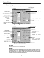
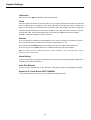
Outline of Main Window ...................................................................................................................................... 2
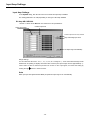
Initializing Settings .............................................................................................................................................. 5
Overview of Steps in Recording and Reproduction............................................................................................. 6
Section 4 Settings ........................................................................................................................... 1
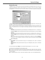
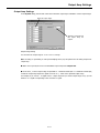
System Settings.................................................................................................................................................. 2
Input Amp Settings.............................................................................................................................................. 6
DC Amp AR-LXDC100 ............................................................................................................................... 6
PA Amp AR-LXPA100 ................................................................................................................................. 7
ST Amp AR-LXST100............................................................................................................................... 10
Sensitivity Setting Using TEDS Functions ........................................................................................................ 12
Auto Offset........................................................................................................................................................ 14
Calibration By Using Calibrator......................................................................................................................... 15
Zero Balance .................................................................................................................................................... 16
Setting Tachometer Pulse Inputs ...................................................................................................................... 17
Output Amp Settings ......................................................................................................................................... 19
Outline of Trigger Recording ............................................................................................................................. 20
Repeat Mode............................................................................................................................................ 20
Interval Mode............................................................................................................................................ 21
Repeat Mode Settings ...................................................................................................................................... 22
Level Trigger Settings ....................................................................................................................................... 25
Interval Mode Settings ...................................................................................................................................... 26
Saving and Loading Settings ............................................................................................................................ 27
Saving Settings ........................................................................................................................................ 27
Loading Settings....................................................................................................................................... 28
Section 5
Operations ...................................................................................................................... 1
Specifying Recording Devices and File Names .................................................................................................. 2
Recording to Memory ................................................................................................................................. 4
Recording to Media (PC Card) ................................................................................................................... 6
Recording to PC ......................................................................................................................................... 8
Notes for reproducing a PC-recorded file by the LX main unit ................................................................... 9
Operations to control recording......................................................................................................................... 10
Exchanging Media.................................................................................................................................... 11
Copying............................................................................................................................................................. 12
Reproducing ..................................................................................................................................................... 13
Operations to control reproduction ........................................................................................................... 14
v
Index
Moving Reproducing Point (Skip) ............................................................................................................. 14
Advanced search...................................................................................................................................... 15
Convenient Features......................................................................................................................................... 16
Displaying Waveform................................................................................................................................ 16
Channel Property ..................................................................................................................................... 17
Displaying Bar Meter ................................................................................................................................ 18
Displaying Digital Values .......................................................................................................................... 18
Viewing Header Information ..................................................................................................................... 18
Changing Modes ...................................................................................................................................... 20
Stopping Fan ............................................................................................................................................ 21
Listening to Data by Sound ...................................................................................................................... 21
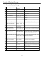
Contents of Displayed Message ....................................................................................................................... 22
LX Stand-alone Operations............................................................................................................................... 25
Recording to Media .................................................................................................................................. 26
Recording to Memory ............................................................................................................................... 27
Reproducing ............................................................................................................................................. 28
Recording Synchronization ............................................................................................................................... 29
Settings and Recording Operations.......................................................................................................... 30
Connecting Recording Synchronization Cables and Turning on Power ................................................... 30
Operations................................................................................................................................................ 31
Others ...................................................................................................................................................... 36
Section 6
Specifications................................................................................................................. 1
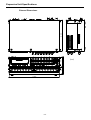
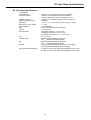
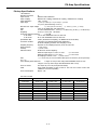
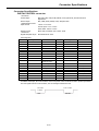
Main Unit Specifications...................................................................................................................................... 2
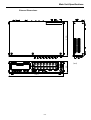
External Dimensions .................................................................................................................................. 3
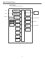
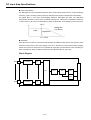
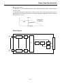
Block Diagram ............................................................................................................................................ 4
Setting Tachometer Pulse Inputs ........................................................................................................................ 5
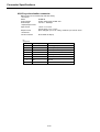
Generator Output Specifications ......................................................................................................................... 6
Expansion Unit Specifications............................................................................................................................. 7
External Dimensions .................................................................................................................................. 8
DC Input Amp Specifications............................................................................................................................... 9
Block Diagram .......................................................................................................................................... 10
PA Amp Specifications ...................................................................................................................................... 11
ST Amp Specifications ...................................................................................................................................... 12
Output Amp Specifications ................................................................................................................................ 14
Block Diagram .......................................................................................................................................... 15
File Format........................................................................................................................................................ 16
Type of Files ............................................................................................................................................. 16
File name.................................................................................................................................................. 16
Directory Structure on Media.................................................................................................................... 17
Data File ................................................................................................................................................... 18
Data File When Turning on Tachometer Pulse Inputs............................................................................... 19
Converting Data to Physical Quantities .................................................................................................... 21
Header File............................................................................................................................................... 22
Connector Specifications .................................................................................................................................. 25
DIGITAL CONTROL connector................................................................................................................. 25
AQ-VU synchronization connector ........................................................................................................... 26
Recording Synchronization Specifications ........................................................................................................ 27
Section 7
Appendix......................................................................................................................... 1
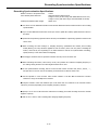
Troubleshooting .................................................................................................................................................. 2
Supplied Accessories and Options ..................................................................................................................... 3
Supplied Accessories ................................................................................................................................. 3
Optional parts ............................................................................................................................................. 3
vi
Section 1
1-1
Preface
Overview
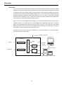
Overview
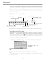
The LX-100 series instrumentation data recorders can record and reproduce signals of a maximum of 48 kHz
sampling frequency via 8 channels onto PC card media in the case of 16bit AD. Recorded data on the media
is stored as PC files. The maximum number of input channels is 32 by using the selectable types of the 8channel input cards and the optional channel expansion unit. You can choose the recording media from
among the followings: Recording to the internal memory or to a PC card. Also, you can save the recorded
data as PC files by connecting to a PC. The file format is TEAC's proprietary TAFFmat format. TAFFmat files
can be loaded into commercially available analysis software.
From a PC you can use the supplied LX Navi software to set recording conditions such as the input range or
sampling frequency. The interface with a PC is hot-pluggable and compatible with IEEE 1394. So, after the
setup, you can disconnect the LX while the power is still on, and start or stop recording by using control
buttons on the main unit. You can choose the 100BASE-TX Ethernet interface as an alternative. You can also
use LX Navi to record or reproduce while connected to a PC.
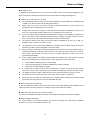
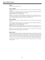
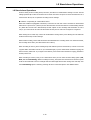
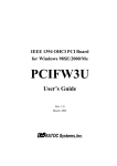
An optional color LCD remote control unit is available to set recording conditions, to record and reproduce,
and to monitor by use of bar meters.
Remote Control Unit
Test0001.dat
LX-100 series
Record
Direct
Input Amp
IEEE1394
Or LAN
Memory
PC Card slot
Reproduce
PC Card
Output Amp
PC Card adapter +Compact Flash
System Diagram
1-2
Features
Features
■ Input/Output Amps
The LX main unit is equipped with two slots and the optional expansion unit provides an additional two slots
for installing the input amps and/or the output amps. The input/output amp provides 8-channel
inputs/outputs from the selections below.
DC input amp card:
Use to connect voltages and/or to connect signals of external amplifiers.
PA amp input card:
In addition to voltages, a voltage output accelerometer input providing an A/C
weighting filter can be connected directly.
ST amp input card:
Use to connect strain gauges (full bridge) and/or gage-type sensors, and also
voltages.
Analog output amp card: Use to reproduce analog signals.
■ Recording Modes
You can use the PC card drive for data recording onto a removable media.
Memory recording:
Recording up to 64MB (add up to 576MB as an option) of internal memory.
Stored data can be transferred to the removable media or the PC.
PC card recording: Stored data on the PC card (Compact Flash + PC card adapter) can be loaded into the
PC by using the PC card slot. By supporting FAT32, you can use a PC card with a
maximum of 8GB as a media.
PC recording:
Recording directly to the PC.
You can also transfer data to a PC while recording to memory or the media, or automatically save to the
media after recording to memory.
■ Quantization Bits
Either conventional 16 bits A/D or 24 bits A/D, providing a dynamic range of 100db, can be selected.
■ Sampling Frequency Series
In addition to the LX-110, which provides two series of sampling frequency - a 96 kHz sampling frequency
and a low-speed sampling, the LX-120 enables one to select as five series of sampling frequency - 102.4 kHz,
100 kHz, 96 kHz, 65.536 kHz and a low-speed sampling.
■ Interface with PC
Either IEEE1394 for high-speed data transfer or 100BASE-TX LAN for network environment can be selected.
■ Real Time Monitor
You can monitor the data as formats of waveforms, bar graphs, and digital displays on the PC display while
recording. And, you can reproduce the recorded data in the internal memory or the media.
■ A Variety of Recording Triggers
Manual:
Starts recording manually.
Level Trigger:
Starts recording by detecting level changes in a specified channel.
External Trigger:
Starts recording by using an external signal as the trigger.
Pre-trigger:
A pre-trigger can record the data that was read into a buffer before a recording-start
condition (based on a level trigger or external trigger) is satisfied.
Post-trigger:
Continues to record for a set period even after a recording-stop condition (based on a
level trigger or external trigger) has been satisfied.
1-3
Features
■ Event Marks
You can mark the data during recording. Then you can search for such event marks when you want to
reproduce some recorded data.
■ Recording and Reproducing Voice Memos
A microphone amp and a speaker are built in so that you can record and reproduce (listen to) voice memos.
■ Synchronization recording of multi units (optional)
An optional synchronization recording can be made in maximum of 4 units (one for a master unit, three for
slave units).
■ Synchronization recording of camera pictures (optional)
A synchronization recording can be made with pictures by connecting the Visual Recorder “AQ-VU”, providing
a recording of 4ch camera pictures.
1-4
About TAFFmat
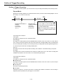
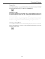
About TAFFmat
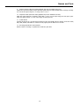
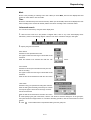
TAFFmat (an acronym for Teac Data Acquisition File Format) is a file format composed of the following: (1)
A data file containing A/D (analog to digital) converted data that is in binary format with the extension dat.
(2) A header file containing information, such as recording conditions, that is in text format with the
extension hdr.
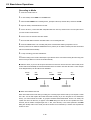
This document uses the term ID to refer to a collection of data collected from the start of recording on the LX
series until the recording is stopped or paused. For each ID, one data file and one header file is recorded. A
voice memo is recorded as a WAV file with the extension wav.
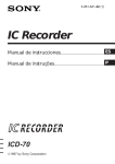
The above files share a common file name, to which is appended an ID number. When a new file name is
specified, this ID number becomes 1. Each time recording starts, this number advances by 1.
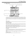
Standby
REC
Start
FWD
Pause
PAUSE
Resume
FWD
Stop
STOP
Aaaaa002.dat
Aaaaa002.hdr
Aaaaa001.dat
Aaaaa001.hdr
A/D-converted data is recorded as 2-byte integers between -32768 and +32767 in the case of 16 bits A/D
and also recorded as 4-byte integers between –8388608 and +8388607 in the case of 24 bits A/D. Negative
numbers are expressed as complements of 2. The byte order is from the lower bytes to the higher bytes. The
sequence of data is as follows: first sampling channel order, second sampling channel order, ....., last
sampling channel order.
In LX-100 series, ±100% of the input range is equivalent to ±25000 of 16 bits A/D or ±6400000 of 24
bits A/D
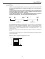
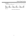
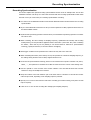
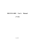
This document uses the term “scan” to refer to a collection of data resulting from one sampling. A data file
consists of scan repetitions.
Example: The data of 1 scan when the sampling frequency is 6 kHz:
Data sequence
ch 1
ch 2
ch 3
ch 4
ch 5
ch 6
ch 7
ch 8
1/6000 sec
1-5
Notes on Usage
Notes on Usage
Use of an UPS is Recommended
We recommend that you use an UPS (Uninterruptible Power Supply) whenever you use an AC adapter. This
can protect important data during a power stoppage. If the power is turned off while a media is in a drive,
data recorded on that media might become unreadable.
Use an optional battery unit to back up the operation on power stoppages.
Use Specified Media Only
Use PC cards checked by TEAC in advance (contact us for information). Other media might be unable to
record or reproduce correctly.
Compact Flash Cards Checked by TEAC for Correct Operations (as of July 2007)
SanDisk Corp.
128MB
1GB
Lexar Media, Inc.
Buffalo Technology, Inc.
Professional
RCF-G series
SDCFB-128-801
SDCFB-1000-801
1GB
CF1GB-80-380
256MB
SDCFB-1024-J60
4GB
CF1GB-133-380
1GB
2GB
SDCFB-2048-J60
4GB
SDCFB-4096-J60NS
Hagiwara Sys-Com
ultra
SDCFB-128-801
1GB
HPC-CF1GZP
512MB
SDCFB-512-801
2GB
HPC-CF1GZP
ultraⅡ
SDCFH-256-903
1GB
SDCFH-1024-903
2GB
SDCFH-2048-903
1GB
SDCFX3-1024-903
2GB
SDCFX3-2048-903
4GB
SDCFX3-4096-903
8GB
SDCFX3-8192-903
RCF-G1G
RCF-G series
2GB
RCF-R2G
Z-Pro series
128MB
256MB
RCF-G256M
I-O DATA DEVICE, INC.
CFX シリーズ
256MB
CFX-256M
CF40 シリーズ
ExtremeⅢ
1GB
CF40-1G
CF115 シリーズ
8GB
CF115-8G
■ Turn off the power after you eject the media
Remove the PC card before powering off the LX. If the power is turned off during writing, data recorded on
the media might become unreadable. Also, eject the media before moving the LX main unit. Further, remove
the media before moving the LX main unit. Moving the unit while the media is inserted might result in
damage.
■ Remove Media
Insert or eject the media after confirming that “MEDIA READY” is displayed on the unit that is in the STOP
state of the REC mode.
■ Never Remove a Recorded File, Never Rename the File/Folder Name of a Recorded File By a Windows
Operation
Do not remove a recorded file or rename a file/folder name of a recorded file by a Windows operation. If you
manipulate the recorded files on the media by a Windows operation, such as partially removing the file, or
renaming the file/folder name, the link between the data file and the header file will be lost or the writing
speed to the media to support the specifications cannot be assured. Also, the data might be unreadable
when such media is re-inserted in the LX.
When reproducing the file recorded on the PC by the main unit of LX, refer to “Notes for reproducing a
PC-recorded file by the LX main unit” on page 9 in Section 5.
1-6
Notes on Usage
■ Handling PC Card
To discharge static electricity from your body, touch a metallic surface near you before handling the unit.
Never touch the PC card being inserted into the PC card slot while recording and playing back.
■ Cautions for recording data on a PC Card
The recognized file system is FAT16 or FAT32. NTFS and FAT12 are not available. (By formatting media
Before using a PC Card on LX, format it in FAT16 or FAT32 by Windows PC. A PC Card that is not
of 16MB or less the file system will normally become FAT12.)
formatted cannot be formatted by the LX main unit.
It might take a long time to recognize or save data when using a FAT32 formatted PC Card on LX. In
In you are using a PC Card that has been repeatedly used for saving or removing data, you might not be
such a case, the situation might be improved by re-formatting on the LX main unit.
able to record data on the PC Card that is supposed to have sufficient free space remaining. In such a
case, re-format the PC Cards again after backing up the data to another media.
The maximum amount of free space on a PC Card, which is displayed on LX Navi, etc., is 4GB. “%”
displayed on the unit means the value is correct.
The maximum file size of the PC card available on LX is 2GB in FAT16 or 4GB in FAT32. However, the
actual file size will be reduced, depending on the unit of data.
When continuing to record data exceeding the maximum size, another new file will be made to keep on
recording automatically. At this time, the header file or the voice file will be moved onto a new file.
These groups (data, header, and voice) of files are recorded separately as above, and can be
reproduced independently.
If the recording condition meets either of the followings, the maximum size of the continuous recorded
data would be 4GB in total. (It might exceed the value, although this is not guaranteed)
1.
Synchronization recording (master or slave setting)
2.
Timer [recording start time, specified recording time, timeout] recording
3.
Trigger [level, external trigger] recording
If so many files are saved on the PC Card, it might take a long time to get the file table of data
reproduced. In such a case, reformat the PC Cards again after backing up the data to another media.
The maximum number of folder or data files that can be made and operated correctly is 10,000.
The number of files exceeding 10,000 can be recorded, but not copied or reproduced.
When using a PC Card with a low writing speed, the recording might be stopped since the data writing
speed does not keep up with it. Use the recommended card only.
■ Button operations of LX main unit
In case you operate the buttons of the LX main unit that is connected with supplied LX Navi software, the LX
might not operate correctly. (Operate the LX Navi first when connected to the LX Navi)
■ About the model without the PC Card drive installed
The drive is not installed. Naturally, the functions concerning the recording to the media are disabled.
■ About No Output Amp Model
The output amplifier is not installed. Naturally, the functions concerning the output amp are disabled.
However, you can view the reproduced data on a PC.
1-7
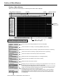
Names and Parts
Names and Parts
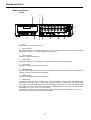
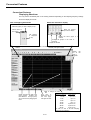
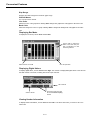
Front
1
2 3
4
5
12
11
10
8
9
7
6
1
Drive
Opening the cover reveals the disk slot.
2
Input level LED
When the input signal for a channel is larger than +/- 10 % of a set input range, the LED glows green. When
the signal exceeds +/- 115 % of the range, the LED glows red.
3
Input connector
Inputs the signal to be measured.
4
Power switch
Pushing the switch up turns on the power. Pushing the switch down turns off the power.
5
Volume knob
Adjust the volume for reproducing voice memos.
6
EARPHONE jack
Connects to an earphone when you are using the earphone to listen to voice memos. When an earphone is
inserted, sound does not come from the speaker.
7
MEMO IN jack
Connects to a microphone used for voice memos.
8
USAGE LEDs
Indicates the usage rate of the recording device. During recording to memory, these LEDs indicate what
percentage of the total memory is being used. During recording to a media, these LEDs indicate what
percentage of the total media capacity is being used. During recording to a PC, these LEDs indicate what
percentage of memory is being used as the buffer for transmitting data. From the left, the LEDs indicate
percentages of 5, 10, 20, 35, 50, 70, 90, and 100%.
These LEDs also function as a low-voltage alarm, and blink when the power voltage falls to 11 V or less.
At this time, recording and reproducing will be stopped.
1-8
Names and Parts
9
Output connector (When the analog playback amp card is installed in the slot.)
Outputs the reproduced signal. Outputs the input signal during recording-standby status or during recording.
You can set the output range in 0.1 V steps, from 1 V to 5 V.
10 Output level LED (When the analog playback amp card is installed in the slot.)
When the output signal for a channel is larger than +/-10% of a set output range, the LED glows green.
When the signal exceeds +/-115% of the range, the LED glows red.
11 P LOCK button
Pressing this button for 3 seconds causes the lamp to glow and disables the five buttons on the left: STOP,
REC, FWD, PAUSE, and EVENT. To release the lock, again press the button for 3 seconds.
12 Recording/reproduction control buttons
Buttons used for recording or reproduction. Details are given later.
1-9
Names and Parts
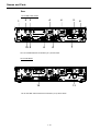
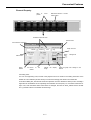
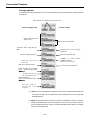
Rear
LX-110 IEEE 1394 Version
1
2
3
4
4
5
6
LX-110
RECORDING UNIT
12-28V ,
6.0-2.6A
BATTERY UNIT:BU-81
TEAC CORPORATION
SERIAL NO.
MADE IN JAPAN
10 9
8
8
7
The LX-110LAN model has an interface (at 7) shown below.
LX-120 LAN Model
LX-120
RECORDING UNIT
12-28V ,
6.5-2.8A
BATTERY UNIT:BU-81
TEAC CORPORATION
SERIAL NO.
MADE IN JAPAN
11
12
The LX-120 IEEE 1394 version has an interface (at 11) shown above.
1-10
Names and Parts
1
FG terminal
Connects the grounding wire.
2 MON OUT connector
Outputs in analog format the signal of a channel during recording-standby status, recording, or reproduction.
You use the supplied LX Navi software to select the channel you want to monitor. You can set the output
range in 0.1 V steps, from 1 V to 5 V. The same filter as used for the output is applied to this monitor output.
(Not available for analog output using low-speed sampling frequency series)
Outputs the generator output signal at the LX-120.
3
EXT TRIGGER IN connector
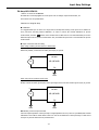
Inputs the trigger signal when using an external contact signal as the trigger to start recording.
4
Cooling fan
Exhaust fans used for cooling the main unit. Do not cover the outlet vent.
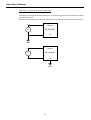
5
BU-81 connector (optional)
Used to connect the optional battery unit.
6
DC IN connector
Inputs power in the range of +11 to 30 V.
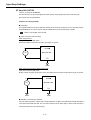
7
IEEE 1394 connector (for IEEE 1394 model)
Connects to a PC. Use a recommended interface card on the PC.
8
Connector for recording synchronization (optional)
It is used for recording synchronization.
9
AQ-VU synchronization connector (optional)
Used to control record start/stop and time setting.
10 DIGITAL CONTROL connector
Used when using a contact signal to control recording or reproduction.
11 100BASE-TX connector (for LAN model)
Connects to a PC. The LED-side of the connector flashes while communicating.
12 PULSE IN A/B connector (LX-120 model)
Connects tachometer pulse inputs.
1-11
Recording time
Recording time
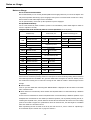
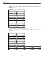
■ Recording to Memory, 8 channels, 16 bits A/D, 64 MB standard memory (when not recording voice
memos)
Sampling frequency ( Value in brackets is the recording
bandwidth with tolerances of +/-0.5 dB)
Recording time
96 kHz
(40 kHz)
40 sec
48 kHz
(20 kHz)
80 sec
24 kHz
(10 kHz)
160 sec
12 kHz
(5 kHz)
320 sec
6 kHz
(2.5 kHz)
640 sec(approx. 10 min)
3 kHz
(1.25 kHz)
1,280 sec(approx. 21 min)
(625 Hz)
2,560 sec(approx. 42 min)
1.5 kHz
■ Recording to PC Card, 8 channels, 16 bits A/D, 1 GB PC Card (when not recording voice memos)
* This recording time at a 48 kHz sampling frequency is the value when using a PC Card on which nothing is
recorded after formatting.
Sampling frequency ( Value in brackets is the recording
bandwidth with tolerances of +/-0.5 dB)
Recording time
48 kHz
(20 kHz)
1,230 sec(approx.20 min)※
24 kHz
(10 kHz)
2,470 sec(approx.41 min)
12 kHz
(5 kHz)
4,940 sec(approx.82 min)
6 kHz
(2.5 kHz)
9,890 sec(approx.164 min)
3 kHz
(1.25 kHz)
19,790 sec(approx.329 min)
(625 Hz)
39,360 sec(approx.11hour)
1.5 kHz
■ Media recording time can be calculated as follows (result for approximate times)
Recording Time (seconds)
= (Media Capacity (Bytes) x 0.9) / [(Number of Analog Input Channels + Number of Tachometer Input
Channels) x Sampling Frequency (Hz) x AD (width) + 8000]
Media Capacity x 0.9: Considering recording overhead of the media and an additional capacity needed for
the header files, multiply 0.9 (90%) for the used capacity for data files.
AD width 2 for 16 bits A/D, 4 for 24 bits A/D
Refer to the tables later for a combination of the Sampling Frequency vs. the number of analog input
channels that can be selected in each recording mode.
The number of tachometer input channels in 16 bits A/D: use "2" in 16 bits mode, "2" for 32 bits/1 channel
mode, or "4" for 32 bits/2 channels mode. In 24 bits A/D: not available in 16 bits mode, "1" for 32 bits/1
channel mode, or "2" for 32 bits/2 channels mode. Tachometer input channels are available for LX-120 only.
Use "0" instead of 8000 when the memo voice recording turns to OFF.
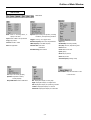
1-12
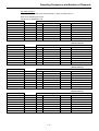
Sampling Frequency and Number of Channels
Sampling Frequency and Number of Channels
A combination of the sampling frequency vs. the number of analog input channels varies depending on the
selected recording mode (e.g., the type of the recording media, the number of tachometer input channels,
etc.).
LX-110 supports the 96 kHz series only in the table of sampling frequency series. Another series is available
as an optional function of LX-110.
Recording Condition 1
Recording mode: Media recording to the PC card, while transferring data to the PC
Memo Voice Recording: ON or OFF
Interface to PC: IEEE1394 or LAN
(16bitsAD/24bitsAD)
1024kHz series
Max. number of analog input channels based on the tachometer input setting
Sampling Frequency(kHz)
Bandwidth (kHz)
No
16bits 2ch
32bits 1ch
32bits 2ch
*102.4
42
4/2
2/Unrecordable
2/Unrecordable
Unrecordable
*51.2
21
8/4
4/Unrecordable
4/2
4/2
25.6
10
16/8
8/Unrecordable
8/4
8/4
12.8
5
32/16
24/Unrecordable
24/8
24/8
5.12
2
32/16
32/Unrecordable
32/16
32/16
2.56
1
32/16
32/Unrecordable
32/16
32/16
1.28
0.53
32/16
32/Unrecordable
32/16
32/16
(16bitsAD/24bitsAD)
100kHz series
Max. number of analog input channels based on the tachometer input setting
Sampling Frequency(kHz)
Bandwidth (kHz)
No
16bits 2ch
32bits 1ch
32bits 2ch
*100
41
4/2
2/Unrecordable
2/Unrecordable
Unrecordable
*50
20
8/4
4/Unrecordable
4/2
4/2
20
8
16/8
8/Unrecordable
8/4
8/4
10
4.1
32/16
24/Unrecordable
24/8
24/8
5
2
32/16
32/Unrecordable
32/16
32/16
2
0.8
32/16
32/Unrecordable
32/16
32/16
1
0.4
32/16
32/Unrecordable
32/16
32/16
(16bitsAD/24bitsAD)
96kHz series
Max. number of analog input channels based on the tachometer input setting
Sampling Frequency(kHz)
Bandwidth (kHz)
No
16bits 2ch
32bits 1ch
32bits 2ch
*96
40
4/2
2/Unrecordable
2/Unrecordable
Unrecordable
*48
20
8/4
4/Unrecordable
4/2
4/2
24
10
16/8
8/Unrecordable
8/4
8/4
12
5
32/16
24/Unrecordable
24/8
24/8
6
2.5
32/16
32/Unrecordable
32/16
32/16
3
1.25
32/16
32/Unrecordable
32/16
32/16
1.5
0.625
32/16
32/Unrecordable
32/16
32/16
1-13
Sampling Frequency and Number of Channels
(16bitsAD/24bitsAD)
65.536kHz series
Max. number of analog input channels based on the tachometer input setting
Sampling Frequency(kHz)
Bandwidth (kHz)
No
16bits 2ch
32bits 1ch
32bits 2ch
*65.536
27
4/2
2/Unrecordable
2/Unrecordable
Unrecordable
*32.768
13
8/4
4/Unrecordable
4/2
4/2
16.384
6
16/8
8/Unrecordable
8/4
8/4
8.192
3
32/16
24/Unrecordable
24/8
24/8
4.096
1.7
32/16
32/Unrecordable
32/16
32/16
2.048
0.8
32/16
32/Unrecordable
32/16
32/16
1.024
0.4
32/16
32/Unrecordable
32/16
32/16
Remarks: Cannot select the moving average other than 1 (one) at the Sampling Frequency settings shown
with *(asterisk).
In 24 bits A/D, 2 ch (16 bits) of tachometer input is not available.
When using LAN as the main unit interface, continuous recording operations might not be possible (it
might be stopped while recording because all of the memory has been used) on setting the maximum
number of recording channels. In such a case, decrease the data transfer rate by decreasing the
sampling frequency by half or by decreasing the number of recording channels by half, and use the LX
main unit.
1-14
Sampling Frequency and Number of Channels
Recording Condition 2
Recording Mode: Recording to the internal memory or direct recording to the PC
Memo Voice Recording: ON or OFF
Interface to PC: IEEE1394 or LAN
102.4kHz series
Max. number of analog input channels based on the tachometer input setting
Sampling Frequency(kHz) Bandwidth (kHz)
No
16bits 2ch
32bits 1ch
32bits 2ch
8/4
4/Unrecordable
4/2
Unrecordable
*102.4
42
*51.2
21
16/8
8/Unrecordable
8/4
8/4
25.6
10
32/16
24/Unrecordable
24/8
24/8
12.8
5
32/16
32/Unrecordable
32/16
32/16
5.12
2
32/16
32/Unrecordable
32/16
32/16
2.56
1
32/16
32/Unrecordable
32/16
32/16
1.28
0.53
32/16
32/Unrecordable
32/16
32/16
(16bitsAD/24bitsAD)
100kHz series
Max. number of analog input channels based on the tachometer input setting
Sampling Frequency(kHz) Bandwidth (kHz)
No
16bits 2ch
32bits 1ch
32bits 2ch
*100
41
8/4
4/Unrecordable
4/2
Unrecordable
*50
20
16/8
8/Unrecordable
8/4
8/4
20
8
32/16
24/Unrecordable
24/8
24/8
10
4.1
32/16
32/Unrecordable
32/16
32/16
5
2
32/16
32/Unrecordable
32/16
32/16
2
0.8
32/16
32/Unrecordable
32/16
32/16
1
0.4
32/16
32/Unrecordable
32/16
32/16
(16bitsAD/24bitsAD)
96kHz series
Max. number of analog input channels based on the tachometer input setting
Sampling Frequency(kHz) Bandwidth (kHz)
No
16bits 2ch
32bits 1ch
32bits 2ch
*96
40
8/4
4/Unrecordable
4/2
Unrecordable
*48
20
16/8
8/Unrecordable
8/4
8/4
24
10
32/16
24/Unrecordable
24/8
24/8
12
5
32/16
32/Unrecordable
32/16
32/16
6
2.5
32/16
32/Unrecordable
32/16
32/16
3
1.25
32/16
32/Unrecordable
32/16
32/16
1.5
0.625
32/16
32/Unrecordable
32/16
32/16
(16bitsAD/24bitsAD)
65.536kHz series
Max. number of analog input channels based on the tachometer input setting
Sampling Frequency(kHz) Bandwidth (kHz)
No
16bits 2ch
32bits 1ch
32bits 2ch
8/4
4/Unrecordable
4/2
Unrecordable
*65.536
27
*32.768
13
16/8
8/Unrecordable
8/4
8/4
16.384
6
32/16
24/Unrecordable
24/8
24/8
8.192
3
32/16
32/Unrecordable
32/16
32/16
4.096
1.7
32/16
32/Unrecordable
32/16
32/16
2.048
0.8
32/16
32/Unrecordable
32/16
32/16
1.024
0.4
32/16
32/Unrecordable
32/16
32/16
1-15
Sampling Frequency and Number of Channels
Remarks: Cannot select the moving average other than 1 (one) at the Sampling Frequency settings shown
with *(asterisk).
In 24 bits A/D, 2ch (16 bits) of tachometer input is not available.
When using LAN as the main unit interface and PC direct recording, continuous recording operations
might not be possible (it might be stopped while recording because all memory has been used) on
setting the maximum number of recording channels. In such a case, increase the data transfer rate by
decreasing the sampling frequency by half or by decreasing the number of recording channels by half,
and use the LX main unit.
1-16
Section 2
2-1
Installation
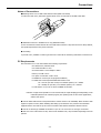
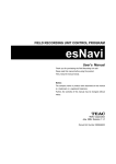
Connections
Connections
Input signal
Oscilloscope, etc.
Supplied Microphone
(when recording voice memos)
Monitor Output
Oscilloscope, etc.
External Trigger(Contact Signal)
Supplied earphone
(when using an earphone to listen
to voice memos)
Optional
Battery Unit
BU-81
DC power※
(+11 ~ 30 V)
Or use the specified
AC adaptor
Tachometer Pulse Inputs(LX-120 only)
LX-120
RECORDING UNIT
12-28V ,
6.5-2.8A
BATTERY UNIT:BU-81
TEAC CORPORATION
SERIAL NO.
MADE IN JAPAN
Remote Control
Unit
Cannot connect
with PC at a time
AQ-VU
Connecters
(Optional)
Connectors for
Sync.
Recording
Connect to PC 100BASE-TX LAN
interface (LAN Model)
Connect to IEEE 1394 interface
(Either is available. Use TEAC
recommended IEEE 1394 interface
card for PC)
(1394 Model)
※ When the DC power voltage falls to +11V or less, the USAGE LEDs flash and the recording and
reproduction stop. If you are recording to memory, quickly copy the data to a media or to a PC.
2-2
Connections
Notes of Connections
■Attaching Ferrite Core on IEEE 1394 Interface cable (IEEE 1394 model)
To reduce the radio noise, attach the supplied ferrite cores on both ends of the IEEE 1394 cable.
■ IEEE1394 connector is available for PC only (IEEE1394 model)
Do not connect devices other than the PC to the IEEE 1394 connector. If any other devices are daisy-chained,
the specified performance may not be achieved.
■ Grounding
To prevent noise, establish a common ground for the LX and all the measuring instruments connected to it.
PC Requirements
We recommend use of a PC that satisfies the following requirements:
OS: Windows XP / Windows 2000
CPU: Pentium4 2GHz or more
Screen Resolution: 1024×768 dpi or better
Memory: 512 MB or more
Free space on hard disk: 2 GB or more
CD-ROM drive: Present (for the program installation)
For IEEE 1393 model: Specified IEEE1394 interface card
For a note PC (PC card model): From RATOC Systems, Inc.: CBFW3
For a desktop PC (PCI bus): From RATOC Systems, Inc.: PCIFW3
For LAN model: use your PC on-board 100BASE-TX interface.
Remarks: It might not be possible to record continuously at a high sampling speed depending on the
relationship between the resident program, the operating state of other driver applications,
and the HDD speed.
■ Use the IEEE 1394 interface card specified above. Please contact us for availability. Other interface cards
might not operate correctly. When installing and setting up the interface card, read the documentation
supplied with the card and set up the card in accordance with that documentation and this manual.
■ Use the on-board type 100BASE-TX interface of your PC. Do not use the PC card type of interface.
■ File sizes or the total number of files, which can be handled on PC, may be limited depending on the file
systems.
2-3
Installing LX-100 Series (IEEE 1394 model)
Installing LX-100 Series (IEEE 1394 model)
An overview of the LX-100 (IEEE 1394 model) installation is explained below. Follow the installation
procedures explained later for each operating system.
1. Attach the interface card to your PC.
2. Install the OHCI driver.
3. Install the LX-100 Series device driver.
4. Install the LX Navi.
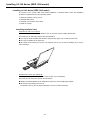
Installing Interface Card
Attach the PC card to your note PC
Insert the IEEE 1394 interface card CBFW3 to your PC card slot met the CardBus specification.
Check with your PC manual for the PC card slot information.
■ You may not insert the IEEE 1394 interface card with other types of PC card at the same time.
■ You may not install it in the upper slot.
■ Be careful when inserting it in your PC. The interface card or your PC may be damaged, if you force it
when inserting it.
Attach the PCI card to your desktop PC
Insert the PCI type interface card PCIFW3 in the PCI slot of your desktop PC.
Check with your PC manual for the PCI slot information.
■ Replace a standard bracket by the supplied low profile one when installing the PCIFW3.
■ Be careful when inserting it in your PC.
The interface card or your PC may be damaged, if you force it when inserting it.
2-4
Installing LX-100 Series (IEEE 1394 model)
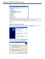
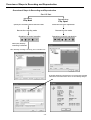
Installing OHCI Driver
The following screen samples are for Windows XP. However, these operations are helpful for Windows 2000.
1. Insert the CBFW3 in the CardBus PC card slot, or insert the PCIFW3 and then turn on your PC. The
standard Windows driver will be automatically installed. Follow the procedures below to confirm that the
driver has been installed correctly.
2.
Double click [Control Panel] from [My Computer to open the Control Panel (classical appearance)
window.
Double click [System] to open the dialog box.
Double click [System] to open the dialog box.
3. Open the system property dialog.
Click [Hardware] tab, and then click [Device Manager(D)].
2-5
Installing LX-100 Series (IEEE 1394 model)
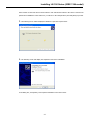
4.
Double click [1394Bus host Controllers], and confirm that “Texas Instruments OHCI Compliant IEEE 1394
Host Controller” is added to indicate that the driver software has been correctly installed.
Now the OHCI driver installation has been completed. Next proceed to the LX-100 Series device driver
installation.
Install LX-100 Series Device Driver
The following screen samples are for Windows XP. However, these operations are helpful for Windows 2000.
1. When the LX-100 is first connected to the PC, the following screen is displayed.
Click [Next].
2. Click [Next]. The Following screen will be displayed.
2-6
Installing LX-100 Series (IEEE 1394 model)
Select “Search for the best driver in these locations” and “Include this location in the search:” Enter the file
path of the CD-ROM drive in the combo-box ( “D:¥Driver” in the example above) and click [Next] to proceed.
3. The following screen will be displayed as Windows copies the required driver.
4. The following screen will display the completion of the driver installation.
In the dialog box, click [Finish]. This completes installation of the device driver.
2-7
Installing LX-100 Series (IEEE 1394 model)
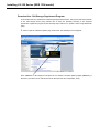
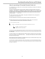
Download the 1394 Storage Supplement Program
From the Microsoft site, download the 1394 Storage Supplement program. This program will fix the problem
of the 1394 storage device (using transfer rate of S400) not operating according to the supposed
specification. Update the program by the following steps. Make sure to update it when using WindowsXP
(SP2).
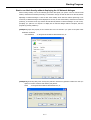
1. Start to open the “Windows Update” page of Microsoft. The following screen will appear.
Enter “KB885222” in the empty box and press the “Go” button to find the update program (KB885222) of
Microsoft. (The above screen was taken from the Microsoft web site of September, 2007.)
2-8
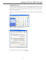
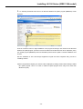
Installing LX-100 Series (IEEE 1394 model)
2. The Following Download Center site for the Microsoft Windows XP update program (KB885222) will be
displayed.
Press the “Continue” button to begin installation of the program according to the contents of the Microsoft
Windows XP update program. (The above screen was taken from the Microsoft web site of September, 2007.)
This update program (KB885222) cannot be installed by Microsoft auto-update. A manual installation must
be done.
Now the installation of the 1394 Storage Supplement Program has been completed. Next, proceed to
“Installing LX Navi”.
※When using Windows XP(SP2), the cautions will be displayed by starting LX Navi without having installed
this update program. There is no need to install the update program when using an OS other than
Windows XP (SP2)
2-9
Installing LX-100 Series (IEEE 1394 model)
Installing LX Navi
To install the supplied LX Navi software:
1. Execute “Setup.exe”, which is in the supplied CD-ROM.
2. Follow the instructions displayed and proceed with the setup.
Click IEEE1394 at the dialog box that will appear in the middle of the installation when using IEEE 1394
model and, then, click OK.
3. After installation, restart the PC.
2-10
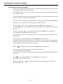
Installing LX-100 Series (LAN model)
Installing LX-100 Series (LAN model)
An overview of the LX-100 (LAN model) installation is provided below.
1. Install LX Navi.
2. Set the IP address of the PC to be connected and the LX-100.
■ Use an on-board type 100BASE-TX LAN interface of your PC.
One-to-one connection with LX-100 using a cross cable
Installing LX Navi
To install the LX Navi software supplied:
1. Set the supplied CD-ROM to CD/DVD drive. The program installation of the LX-100 Series will start to run.
If the program will not run, execute “Setup.exe” in the CD-ROM.
2. Follow the instructions displayed and proceed with setup.
Click Ethernet at the dialog box that will appear in the middle of installation when using the LAN model and,
then, click OK.
3. After the installation, restart the PC.
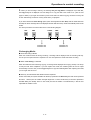
2-11
Installing LX-100 Series (LAN 1394 model)
About IP Address Settings
Consult your network administrator when connecting the LX-100 series to your network per the following
information. Basic knowledge about the Windows network system is required to set the network connection
parameters.
■ The default settings of the LX-100 Series are as follows. Modify the settings (such as the IP address) as
necessary. How to change: Click the portion of the IP address in LX Network dialogue to display LX Property
dialogue. You can create settings for parameters of the IP address or recorder name (Name). (For detail of
the settings, refer to the next item of
“Starting Program” )
IP address: 192.168.0.10
Subnet mask: 255.255.255.0
Gateway: 0.0.0.0
DHCP client: DISABLE
■ To communicate at 100 Mbps, all devices in the path from the LX-100 to the controller PC must support
100 Mbps. Use a cable that is Category 5 or better. To ensure communication quality, we recommend that
you use STP cables and a switching hub that supports STP cables.
■ Depending on the network environment being used, it is possible that you will encounter delays in data
transmission or congestion in processing. In such a case, try the following to improve the situation:
1) If a repeater hub is being used, change to a switching hub instead.
2) Reduce the number of broadcast packets as much as possible.
3) Use a communications path that does not pass through a router as much as possible.
■ However, in a situation such as when the LX-100 is in a remote location and communications are
constrained by low-speed paths, use the LX-100 with a reduced sampling rate.
■ The LX-100 LAN interface carries out TCP connection continuous communications. However, if a packet
from the other party does not arrive within 180 seconds, a timeout occurs and the other party is
automatically disconnected. So, in the event that a normal termination was not possible because of some
problem, such as a PC hang-up or disconnected cable, wait 180 seconds and then try reconnecting.
■ If the PC enters a standby status while LX Navi is being used, communications will cease, and a timeout
will cause a disconnection. If you are using the PC for a long time, make sure that the system standby setting
in the Windows power options is not selected.
■ With the LX-100 LAN interface, the LX-100 can be operated as a DHCP (Dynamic Host Configuration
Protocol) client, but if an IP address cannot be obtained within 30 seconds after startup, the LX-100 starts
those usual operations with a fixed IP address.
■ If you establish a firewall on your PC or install virus check software, you may not connect the LX. Check
the security level of the program on your PC. The ports to be used at LX Navi (LAN model) are as follows:
Control port
49408 (TCP)
Data transfer port
49664 (TCP)
UDP port
49920 (UDP)
For other settings, such as IP address parameter settings and network usage, consult your network
administrator before using the LX-100.
2-12
Starting Program
Starting Program
After installing the drivers and LX Navi and connecting the PC and the LX, start LX Navi.
■ Do not run LX Navi together with application software that uses a lot of memory.
To start LX Navi:
1. On the LX-100 main unit, push up the power switch to |.
When the power is turned on, the input amp is automatically calibrated. During calibration, the input amp LED
will blink. When it finishes, the LED will turn off.
Then, the input amp LED turns off.
2. Start LX Navi.
After LX Navi starts, if you power off the LX-100 main unit or remove the IEEE 1394 cable, LX Navi will display
an error message and terminate. In such a case, if you turn the power back on or reconnect the cable, and then
restart LX Navi, the LX-100 can again be recognized.
In the case of the LX-100, if you power off the LX-100 main unit or remove the LAN cable, not only will
communications fail, but also the network will experience congestion in processing. Make sure to close LX Navi
first to detach the LX-100 from the network. Do not power off the LX-100 before closing LX Navi.
■ It is taking an excessively long time for the LED to turn off.
After you power on the main unit, if it takes an excessively long time for the input amp LED to turn off, the amp
may not have been recognized. In that case, turn the power on again.
■ Do not put the PC into sleep mode.
Set your PC's sleep mode to OFF. If the PC goes into sleep mode, an error will occur on the LX Navi. Make sure
the system standby setting in the screen saver or Windows power options is not selected. Note that some
notebook PCs automatically go into sleep mode just by folding the display.
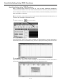
For LX-100 Series (IEEE 1394 model)
Check the box at the serial field of the LX Network dialog box by confirming that the correct serial number is
displayed, and then click OK. In addition, a previously used serial number will automatically contain a check in
the box.
2-13
Starting Program
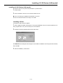
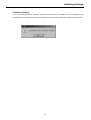
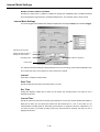
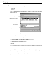
For LX-100 Series (LAN model)
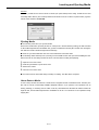
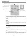
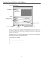
The following dialog box is displayed when LX Navi starts.
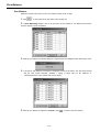
Check the box at the serial field LX Network dialog box by confirming that the white-out box has appeared
and the correct serial number are displayed, and then click OK. In addition, a previously used serial number
will automatically contain a check in the box.
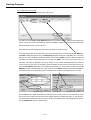
If the whiteout box has not appeared, follow the next pages for a proper set up.
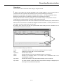
The upper part lists the LX-100 series that exist in the same segment. If you click where the IP address or
the name is displayed in the list area, the LX Property dialog box will appear. In this dialog box, you specify
settings, such as the IP address parameters and the recorder name (Name). Enter the address parameters
that match the network environment that you are using. For Name, you can use any string of up to 32
characters. This name is displayed in the list at startup. So, use a name that differentiates the particular
LX-100 series from any others. If the DHCP system is available for the network environment that you are
using, the IP Address parameters can be obtained automatically. So, in case that you want to set the IP
Address parameters automatically, turn on the check box of the DHCP. Consult your network administrator
to confirm whether or not the DHCP system is available for the network environment that you are using.
Click the OK button to apply the IP address parameters for the LX-100 series. It is not necessary to restart
the LX-100 series. It takes a few seconds for the changed settings to actually take effect. So, wait at least 5
seconds and then connect to the LX-100 series. If the list is not updated or the entry disappears from the list,
click the Update List button to update the list.
2-14
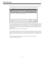
Starting Program
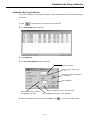
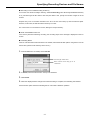
Note that if the LX-100 series is already being used for another PC, a red check mark is displayed and USE
is displayed in the status field. In such a case, you cannot connect to that LX-100 series.
If a TCP connection is not possible because of a problem such as an incorrect IP address for the same
segment, a grey check box will be displayed along with IP ERR in the status field. In that case, specify an
appropriate IP address or check the IP address settings (Subnet mask, Gateway, etc.) between the PC and
the LX-100, and then connect to the LX-100 series.
When connecting to an LX-100 series that exists in a different segment (and, for example, going beyond the
router), select the IP Direct check box, enter the address of the device to be connected, and then click OK.
2-15
Starting Program
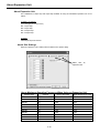
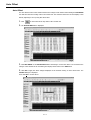
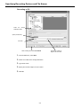
When multiple LX-100 series are found in the same segment, the dialog box appears as shown below. In
such a case, select the check box of the LX-100 series to be connected, and click the OK button.
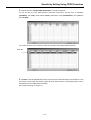
On a real time PC recording of the LX-100 series (LAN model), the speed of the data transfer cannot catch up
to the recording throughput a time unit. In this scenario, the recording will stop automatically when the
memory buffer of the LX becomes full with un-transferred data. It is caused by depending on the PC
specifications and the network traffic. However, the following sampling setting is not applicable for the real
time PC recording.
Sampling Frequency 96 kHz x
8 ch (Memo voice ON/OFF)
If, by using LX Navi, multiple LX units are connected to a single PC (with IEEE 1394 or LAN), the waveform
settings and the data folder settings of each LX may conflict with others because the LX Navi shares the
common save area. So that every PC has its own LX within a multi environment, use a separate PC for each
LX.
The Main Window will be displayed by starting LX Navi when the connection is completed.
See “Section 3 Introduction to LX Navi”.
2-16
Starting Program
Start to run Navi directly without displaying the LX Network dialogue
When running LX Navi, refer to the following procedure and specify “/D” option. If the LX with the serial
number, which has been started previously, is connected to the I/F, LX Navi will start to run directly without
displaying LX Network dialogue. If the LX with serial number, which has been started previously, is not
connected, LX Network dialogue will be displayed. If the only LX with serial number, which has been started
previously, is connected to the I/F, LX Navi will start directly without LX Network dialogue. In such a case,
specifying “/D” option is not required. To display the LX Network dialogue without exception, start the
program by pressing “Shift key”.
(Example 1) Open the property of the LX Navi short cut icon and add “ /D” option to the path of link
destination as follows.
Link destination
"C:¥Program Files¥TEAC¥LX Navi¥LxNavi.exe" /D
(Example 2) From the [Start] menu select [Run] and enter the directory path and “LxNavi.exe” with “/D”
option to execute as follows and click the [OK] button.
Name
"C:¥Program Files¥TEAC¥LX Navi¥LxNavi.exe" /D
2-17
Inserting and Ejecting Media
Inserting and Ejecting Media
Inserting Media
■ Insert or eject the media when the LX is at the STOP state of the REC mode.
■ To discharge static electricity from your body, touch a metallic surface near you before handling the unit.
Never touch the PC card being inserted in the PC card slot while recording and replaying.
1. Power on the LX main unit. Wait until the STOP lamp glows before proceeding to the next step.
2. Open the cover of the drive.
3. Insert the media, with the label facing up, into the slot.
4. Close the cover of the drive.
■ To ensure the recording performance of the main unit, use the PC cards specified in “Notes on Usage” of
Section 1 “Preface”.
2-18
Inserting and Ejecting Media
PC Card
On the PC, format the PC Card to FAT16 or FAT32 (not quick format) before using. Format the PC Card
exceeding 2GB to FAT32. (The format operation from the File menu of LX Navi is a quick format.) Type the
volume name and then click Format.
Ejecting Media
■ Turn off the power after you eject the media
Remove the media before powering off the LX. If the power is turned off during writing, the data recorded
on the media might become unreadable. Also, eject the media before moving the LX main unit. Moving the
unit while the media is inserted might result in damage.
■ Insert or eject the media when the LX is at the STOP state of the REC mode.
■ To discharge static electricity from your body, touch a metallic surface near you before handling the unit.
Never touch the PC card being inserted in the PC card slot while recording and replaying.
1. Open the cover of the drive.
2. Push the eject button to eject the PC Card.
3. Remove the media.
4. Close the cover of the drive.
■ You cannot remove the media during recording or reading. The data will be corrupted.
About Data on Media
In a PC's drive, the data recorded on a media can be recognized as files in TAFFmat format. Therefore, the
files can be read by commercially available analytical software. If you perform a file operation such as
moving, deleting, or renaming a file or folder on the PC, the link between the data file and the header file
might be lost, and the data might become unreadable on the PC. You should do no file operation except
copying files.
2-19
About Expansion Unit
About Expansion Unit
The combinations of input amp and output amp available for using AU-LX100EPIO expansion unit are as
follows.
16 inputs + 16 outputs
(From the upper slot to the lower)
Slot 1: Input amp
Slot 2: Input amp
Slot 3: Output amp
Slot 4: Output amp
32 inputs
Install input amps into all slots.
About Slot Settings
When the expansion unit is added, tabs are added to the System dialog.
Added tabs by
expansion units
About Maximum Sampling Frequency When Using an Expansion Unit
AD data length
Channels
Memory Recording
Media Recording (PC card)
16bitsAD
2 ch
96 kHz
96 kHz
16bitsAD
4 ch
96 kHz
96 kHz
16bitsAD
8 ch
96 kHz
48 kHz
16bitsAD
16 ch
48 kHz
24 kHz
16bitsAD
32 ch
24 kHz
12 kHz
24bitsAD
2 ch
96 kHz
96 kHz
24bitsAD
4 ch
96 kHz
48 kHz
24bitsAD
8 ch
48 kHz
24 kHz
24bitsAD
16 ch
24 kHz
12 kHz
24bitsAD
32 ch
12 kHz
6 kHz
2-20
Section 3 Introduction to LX Navi
3-1
Outline of Main Window
Outline of Main Window
When you start the LX Navi program, the following main window will be displayed.
Status dialogue display area
Menu bar
Toolbar
Status bar display
Waveform
display area
Time axis scaler
Waveform display
Status Dialogue Display Area
for
Switch between the recording mode(REC) and the view mode(VIEW)
Confirm the device for recording or reproducing (MEMORY, CARD, and PC)
Confirm the directory name for recording or specify/confirm the directory for reproducing
Confirm the file name for recording or specify/confirm the file for reproducing
Confirm the contents of the comments, which has been entered
Specify and confirm the sampling frequency for recording/reproducing
Specify and confirm the ON/OFF of voice memos recording
Specify and confirm the monitor channels
Remaining time (hour:mimute:sec) for recording on the specified device of the LX main unit
and the ratio of the free space size(%) to total size of the media
※If the remaining time is displayed in cyan color, it indicates that the media has a free space
of 4GB or more and that the actual remaining time is much longer than the displayed time.
Remaining time (hour:minute:sec) for recording on the PC
※If the data transfer speed is low, this item is displayed in yellow or red and it indicates
that the data transfer to the PC is delayed. In such a case, the memory in the LX main
unit might become full and the recording may finish earlier than the recordable time that
is being displayed.
The unit name or the serial number of the LX main unit
3-2
Outline of Main Window
Menu Bar
Main Menu
New: Select a recording device, or
specify a file name
System: System settings of operation, recording
conditions, and reproducing conditions
Open: Select a data to be reproduced
Trigger: Settings of a trigger action
Copy: Copy a data
Params: Property: Save and Load parameters
Stop: Stop
Format: Format a media
TEDS Property: Load TEDS Property
RecStandby: Recording standby
Exit: Exit application
Channel Unit: Auto offset
Rec/Play: Record / Reproducing start
Calibrations
Zero Balancing: Zero balance
Pause: Pause
Event: Write event mark
Eject: (Eject)
Back: Skip to previous
Next: Skip to later
Search Property: Setting of skip
About LXNavi:Help(the information of the
current version)
Fan:Stop a fan forcibly (On/Off)
Speaker:Reproduce a data by
sounds (On/Off)
Amp Calibration:Execute Calibration
Bar:Display/Non-display of a Bar graph
Digit:Display/Non-display of a Digital value
Hdr:Display/Non-display of reproducing a header
Toolbar:Display/Non-display of a Tool bar
Status Bar:Display/Non-display of a Status Bar
3-3
Outline of Main Window
Tool bar
Select device to be recorded,
specify directory or file name
Stop
Recording Stand-by
Select reproducing data
Start
Copy data
Pause
Format media
Settings
of
operation,
recording/reproducing
conditions
Write event mark
Settings of trigger action
(Eject)
Save and Load parameters
Load TEDS Property
Skip to later
Auto offset
Calibrations
Skip to previous
Setting of skip
Zero balance
Stop fan forcibly (On/Off)
Reproduce data by sound (On/Off)
Execute Calibration
Display/Non-display of
reproducing header
Display/Non-display of Digital value
Display/Non-display of Bar graph
Display of Status Bar
Display of Operating Mode
STOP: Idle status
RECSTANDBY: Recording standby
REC: Recording now
PLAY: Playing now
PAUSE: Pause playing
Display of Media Status
MEDIA READY: Media is ready
NO MEDIA: No media exist
BAD MEDIA: Bad media
RUNNING: Running standby
READING: Reading DATA
WRITING: Writing DATA
FORMATTING: Formatting media
EJECTING: Ejecting media
MEDIA ERROR: Read/Write error on media
UNFORMAT: Not formatted
PROTECTED: Write protected
MEDIA FULL: Media is full
Elapsing time
Number
marks
of
event
Display of Modes
Date & Time:
Current date & time on recording
mode,
Recording
date
on
reproducing mode.
3-4
RECORD is recording mode
VIEW is reproducing mode
Remaining time of
fan stop
Initializing Settings
Initializing Settings
In case the setting parameters, which are saved in the LX main unit, are initialized, such as changing the amp
configuration of LX, the following message will be displayed. In such a case, confirm the settings and change them.
3-5
Overview of Steps in Recording and Reproduction
Overview of Steps in Recording and Reproduction
Start LX Navi
Recording
File, New
Reproducing
File, Open
Specify the recording device and file name
Select the file to be reproduced
Become the recording mode
Become the view mode
Operations to control recording
Operations to control reproduction
When the memory
recording is selected
After finishing recording to memory, store on media or PC
By double clicking the specified item of recording data, detailed
information of the data will be shown as the following dialogue.
3-6
Section 4
4-1
Settings
System Settings
System Settings
To specify settings of the LX operations, choose System from the Setup menu.
Tabs for setting items
for LX-110
Enable the slot
Specify the number of
quantization bits
Number of channels
recording at the slot 1
used
for
Select sampling frequency
Record voice memos
Stop fan during recording
Lock the panel
Settings for
channels
Calibration
monitor
output
Setting for monitor output
range
Set the clock
Apply the same channel
settings as the channel last
changed
Execute zero balance automatically when setting ST amp.
Adjust to PC clock before REC STANDBY
Tabs for setting items
for LX-120
Enable the slot
Specify the number of
quantization bits
Number of channels used
for recording
Select sampling frequency
at the slot 1
Record voice memos
Tachometer input
setting overview
Stop fan during recording
channels
Lock the panel
Calibration
Settings for monitor output
channels
Set the clock
Settings of monitor output
range and generator output
Apply the same channel
settings as the channel
last changed
Execute zero balance automatically when setting ST amp.
Adjust to PC clock before REC STANDBY
AD Width
Select either of 16 bits or 24 bits as a quantization bits.
Sample
Select the sampling frequency. Select the sampling frequency series, including the sampling frequency to be
selected at the upper row. Then, select the sampling frequency within the list shown at the lower row. They
are to be limited, based on the selected recording media and the tachometer pulse input channels. See
“Sampling Frequency and Number of Channels” on page 1-13.
4-2
System Settings
f
or LX-110
In LX-110, you can select the sampling frequency series of 96k-1.5k and 1k-1/60 only at the upper row. You
also can set a sampling frequency of 96 kHz, 48 kHz, 24 kHz, 12 kHz, 6 kHz, 3 kHz, or 1.5 kHz in 96k-1.5k at
the lower row and set one of 1 kHz、500 Hz、200 Hz、100 Hz、50 Hz、20 Hz、10 Hz、5 Hz、2 Hz、1 Hz、1/2 Hz、
1/5 Hz、1/10 Hz、1/30 Hz、1/60 Hz in 1k-1/60.
for LX-120
In LX-120, in addition to 96k-1.5 and 1k—1/60 series, you can select another sampling frequency from the
following: 100k-1k (100 kHz, 50 kHz, 20 kHz, 10 kHz, 5 kHz, 2 kHz, or 1 kHz) 102.4k-1.28k (102.4 kHz,
51.2 kHz, 25.6 kHz, 12.8 kHz, 5.12 kHz, 2.56 kHz, or 1.28 kHz) 65.536k-1.024k (65.536 kHz, 32.768 kHz,
16.384 kHz, 8.192 kHz, 4.096 kHz, 2.048 kHz, or 1.024 kHz)
Memo
Set to ON when recording or reproducing a voice memo. Voice memo data is recorded as a voice memo file
separately from the data and header files, using 8,000 bytes per second. Note that this data increases even
when the microphone has been removed from the jack.
■ In case both of the media (Memory or Card) and the PC are specified as a destination of recording and setting ON at
the recording of voice memo, the data file of voice memo is created on the media of the LX main unit only, not on the PC.
■ A voice memo is not recorded during the pre-trigger period. In playback, the voice is replayed from the beginning of
the data. So, the voice and data are not synchronized.
Pre-Trigger
Reproducing data
Reproducing voice memo
Fan
When you set this to OFF, you can stop the cooling fan on the LX-100 for a period of 10 minutes from the
start of recording. This is useful for recording noise. If you have already stopped the fan and recorded data,
wait for about 10 minutes before you again stop the fan and record.
When you set this to ON, the cooling fan is turned to on. However, by clicking the fan stop button on the
toolbar, you can stop the fan while recording. Click again to restart the fan. An accumulated time to stop the
fan within a single recording (from recording start to stop) is 10 minutes. The remaining time to stop the fan
is displayed at the status display. (See "Display of Status Bar" on page 3-4.)
Panel
When you set this to Lock, you can disable the control buttons on the front of the main unit.
4-3
System Settings
Calibration
When you set this to ON, the calibration will start automatically.
Clock
Use this to adjust the internal clock on the main unit. The current date and time according to the internal
clock are displayed here. To change the date, click the ▼ button on the right of the date. A calendar will
appear. In the calendar, click the desired date. To change the time, click the digits you want to change and
then either type the desired time or click the ▲ or ▼ button on the right of the time to increase or decrease
the time value. After you have changed the date or time values, click Set to apply the new settings.
Click PC to set the date and time of the PC connected.
Slot Use
Turn on a check box to enable the corresponding slot to be used for recording or reproduction. For Slot 1,
you can choose the number of channels to be used for recording from 2, 4, or 8.
Use the slot tab of the System dialog for the settings of the input and output amps enabled here.
At the LX-120, turn on the Tacho check box to enable the tachometer pulse input channels.
■ You cannot use the tachometer pulse input channels and the generator output
function at the same time.
Same Setting
In case it is necessary to set amp for each channel, turn on the check box to apply the same settings to the
channels as the channel last changed.
Auto Zero Balance
In case a ST amp is installed, turn on the check box to start the zero balance automatically after settings
Adjust to PC Clock Before REC STANDBY
Turn on the check box to set the time of the LX main unit according to the PC
4-4
System Settings
Monitor/Generator
In Signal, select the monitor channel or the type of the generator output signals (only for the LX-120) to be
output from the MON OUT connector on the rear panel. If you don't want to monitor any channel, set NONE.
Click Property to set the output range of the monitor channel or the details of the generator output signal.
In Signal, select the monitor channel or the type of the generator output signals (sine, sweep sine, pulse,
pink noise, or white noise from the MON OUT connector of the LX-120).)
When you select the generator output signal, you can select the following parameters that appear at the
dialog. (The parameters that can be set appear automatically, depending on the selection of the output
signal.)
Sin/Sweep
Start Freq: Set the start frequency (Hz) in the range of 0 to 43000(Hz) when <sine> or <sweep sine>
is selected at Signal. However, the upper limit of the monitor output frequency is 1/2.4 of the sampling
frequency.
Stop Freq: Set the sweep stop frequency (Hz) in the range of 0 to 43000(Hz) when <sweep sine> is
selected at Signal. However, the upper limit of the monitor output frequency is 1/2.4 of the sampling
frequency.
Rate: Set the sweep rate (Hz) in the range of 0 to 80(Hz) when <sweep sine> is selected at Signal. If
the value is too much, it might take a long time for monitor output of the frequency specified at Start
Freq and Stop Freq.
Pulse
Pulse Width: Set the pulse width in the range of 0 to 65535(msec) when <pulse> is selected at
Signal.
Pulse Interval: Set the pulse interval in the range of 0 to 65535(msec) when <pulse> is selected at
Signal.
You can set output range in Range. You can select the output range of 1 V to 5 V in 0.1 V steps.
See Section 6 for the specifications of the generator output.
■ You cannot use the tachometer pulse input channels and the generator output function at the same time.
■ You cannot use the monitor output of the analog signal when recording at the low-speed sampling series
(1 kHz to 1/60 Hz).
■ The available frequency of sine or sweep sine for generator output is 1/2.4 of the sampling frequency.
4-5
Input Amp Settings
Input Amp Settings
In the System dialog, click the tab of the slot in which the input amp is installed.
The setting parameters are valid, depending on the type of the amps installed.
DC Amp AR-LXDC100
<DC100> is shown at the Slot tab. See Section 6 for the specifications.
Select input range
Confirm input level
Confirm input level of every channel
Stop confirming input level
Set input range automatically
Range Settings
You can select the value from ±0.5、1、2、5、10、20、50 V. A range of +/- 131% of the selected range can be
obtained for AD (analog to digital) conversion value. However, the input margin level is approximately +/120%. Select a value so that the input does not exceed ±120%. Input signal, and create the setting by
clicking the right
button to check the level.
Auto
When you input the signal and click Auto, the optimum input range is set automatically.
4-6
Input Amp Settings
PA Amp AR-LXPA100
<PA100> is shown at the Slot tab.
AR-LXPA100 is a PA amp applied for some inputs such as voltage output accelerometer, etc.
See Section 6 for the specifications.
Cautions on Using PA Amp
■ Calibration
It is suggested that you use the 0.01 V range of the LX PA amp after turning on the power for 10 minutes or
more, and then executing manual calibration. In order to execute the manual calibration for precise
measurement, click the
button on the toolbar of the LX Navi. Also it is recommended that you use the
balanced input mode for precise measurement. Also, the balanced input mode is recommended for precise
measurement.
■ Input Connection and Grounding
When using a battery-powered sensor or IEPE sensor
Input Mode: Balanced (Bal) mode
Whenever possible, connect the LX frame ground (FG) to ground.
+
+
AR-LXPA100
Vs
-
LX main
-
FG
GND
When using the AC-powered sensor amp
Input Mode: Balanced (Bal) mode
Always connect the frame ground (FG) of the input signal source and the LX frame ground (FG) to ground.
+
+
AR-LXPA100
Vs
-
LX main
-
GND
FG
GND
■ Handling a reserved input terminal
Since the input impedance of the input amp is a high impedance of 1MΩ, there is a possibility that external
disturbance noise will be mixed with the data. You can set the maximum of the input range or short-circuit
the input to prevent interference by external noise.
4-7
Input Amp Settings
When using a conventional AC powered signal output
Input Mode: Unbalanced (Unbal) mode
If the frame ground (FG) of the input signal source is connected to ground, do not connect the LX frame
ground (FG) to ground.
If there is no frame ground (FG) of the input signal source, connect the LX-100 frame ground (FG) to ground.
+
+
AR-LXPA100
Vs
-
LX main
-
FG
GND
+
+
AR-LXPA100
Vs
-
LX main
-
FG
GND
4-8
Input Amp Settings
AR-LXPA100 Setting Dialog
Select the input range(0.01 V、0.0316 V、0.1 V、0.316
V、1 V、3.16 V、10 V、50V)
Confirm input level of every channel
Stop confirming input channel
Set input range automatically
Select: Balanced or Unbalanced input
Bal: Balanced
Unbal: Unbalanced
Automatically set to DC coupling for all the
8 channels when the unbalanced input is
selected
Select the coupling mode
AC: AC coupling
DC: DC coupling
Select turning ON or OFF of the power supply
to the sensor connected.
OFF: No supply
4mA: Supply 4 mA constant current
AR-LXPA100 Setting Dialog
Select the weighting filter.
A: A filter
C: C filter
FLAT: Flat
Select HPF (High Pass
Filter).
OFF: No
10Hz: 10 Hz
20Hz: 20 Hz
Bal/Unbal: Only a combination of DC/OFF/FLAT selections is applicable at Unbal.
■ At the AR-LXPA100 amp, the sensor power supply voltage is 28 V DC as a standard setting. Contact TEAC
for a 24 V DC setting.
4-9
Input Amp Settings
ST Amp AR-LXST100
<ST100> is shown at the Slot tab.
The AR-LXST100 is an input amp applied for strain gauges, strain gauge type sensors and DC inputs.
See Section 6 for the specifications.
Cautions on Using ST Amp
■ Calibration
It is suggested that you use the ST amp after turning on the power for 20 minutes or more, and then perform
manual calibration. In order to perform manual calibration for precise measurement, click the
button on the toolbar of the LX Navi.
■ Input Connection and Grounding
When using sensors:
Input Mode: Balanced (Bal) mode
Whenever possible, connect the LX frame ground (FG) to ground.
+
+
AR-LXST100
Vs
-
LX main
n
-
FG
GND
When using the AC supply powered sensor amp
Input Mode: Balanced (Bal) mode
Always connect the frame ground (FG) of the input signal source and the LX frame ground (FG) to ground.
+
+
AR-LXST100
Vs
-
LX main
n
-
FG
GND
GND
■ Handling a reserved input terminal
Since the input impedance of input amp is a high impedance of 1MΩ, it is possible that external disturbance
noise will be mixed with the data. You can set the maximum of the input range or short-circuit the input to
prevent the interference by external noise,
4-10
Input Amp Settings
AR-LXST100 Setting Dialog
Select the input range
Click uST to turn the button at the right bottom to mV/V.
Confirm input level of every channel
Stop confirming input level
In case of ST100 amp, the
function, which can set input
range automatically, is not
available.
Change the input range display
between uST and mV/V.
Set the low pass filter.
Change the bridge voltage.
Turn to OFF to set the DC input range.
4-11
Sensitivity Setting Using TEDS Functions
Sensitivity Setting Using TEDS Functions
When a transducer/sensor conforms to the IEEE Std 1,451.4 A SMART TRANSDUCER INTERFACE is
connected to the AR-LXPA100. The LX can read its Transducer Electronic Data Sheet (TEDS) information and
then can display the information and set the acquired sensitivity coefficient automatically to the channel to
which the transducer is connected.
■ If the information of the transducer does not comply with the IEEE TEDS standard template(ver0.9), the
LX cannot read and display the information correctly.
1. Click the toolbar icon
in the main window.
2. The TEDS dialog is displayed.
If you turn ON the power of the LX after connecting the TEDS transducers, the TEDS information is
automatically loaded at the initial calibration stage, and the LX displays the following window shown below.
3. Click Update to read the TEDS transducer information.
If you turn ON the power of the LX after connecting the TEDS transducers, the TEDS information is
automatically loaded at the initial calibration stage, and the LX displays this window.
4-12
Sensitivity Setting Using TEDS Functions
4. Click OK when the <Update TEDS information> message is displayed.
You can view the list of the TEDS transducer information connected to the amp, such as; Sensitivity
(sensitivity), Unit (unit), Serial number (serial), Manufacturer name (manufacturer), and Calibration
date (cal date).
Turn on the check box of the channel to reflect the sensitivity of the loaded TEDS information.
Check Box
5. Click OK to write the applicable slope value (reciprocals of the loaded sensitivity) to the header file. Then,
the window is closed. Open the channel property list at the main window to confirm that the slope value is
updated based on the loaded TEDS information.
(See “Channel Property” on page 5-17.)
4-13
Auto Offset
Auto Offset
The auto offset function of the LX Navi measures the voltage of each channel when clicking the Auto Offset
icon and then reflects its voltage value to the header file. The waveform data in the LX Navi displays Y-axis
data by adjusting to zero by using this offset value.
1. Click
on the toolbar at the stop state of the LX main unit.
2. The Channel Unit table is displayed.
3. Click Auto Offset on the Channel Unit table at the timing to execute the offset. The LX measures the
voltages of the channels at the click timing and displays these values in the offset field
4. Click OK to apply the offset
voltages displayed on the channels turning on their check boxes. The
Confirm dialogue is displayed.
Then click Yes to set the values.
4-14
Calibration By Using Calibrator
Calibration By Using Calibrator
You can use a calibrator or a piston phone to apply a sensor sensitivity based on the actual measurement at
the PA amp.
1. Click
on the toolbar at the stop state of the LX main unit.
2. The Channel Unit table is displayed.
3. Click Calibration.
4. The Cal. Sound/Vibration dialog is displayed.
Select the channel.
Select the type of the sensor
to use.
Select to use RMS or Peak value
for calibration.
Start calibration.
Apply the calibration result to the slope value.
Set the output level to match to
the calibrator to be used.
Being displayed the progress of the calibration.
5. After the calibration has been performed, click Exit or click
4-15
to return to the main window.
Zero Balance
Zero Balance
Whenever turning on the power, use the zero balance function at the ST amp.
1. Click
on the toolbar at the stop state of the LX main unit.
2. In Zero Balancing dialogue, turn on the check box of the channel for zero balance and click the
“Execute” button to start zero balance.
3. While in zero balance, the following dialogue is displayed and then disappears after showing the result.
4.
The result of each channel’s zero balance is displayed on items of the “State”. The “OK” means normal
and the “NG” means abnormal. Establish a setting of range value at the maximum of
100000uST/50mV/V on the channel with no input signal.
5. After the zero balance is completed, click Exit or click
4-16
to return to the main window.
Setting Tachometer Pulse Inputs
Setting Tachometer Pulse Inputs
The LX-120 equips two of the tachometer pulse input channels in separate analog input channels. Their
input connectors are located on the rear panel.
Either 16 bits or 32 bits mode can be selected. When you select the 16 bits mode for one channel, another
channel is automatically effective at 16 bits mode. In 32 bits mode, you may select only one channel.
However, if 24bits A/D is specified, 16 bits mode cannot be specified.
See Section 6 for the specifications.
■ 1 x 16 bits tachometer pulse input channel is equivalent to 1 x analog input channel. 1 x 32 bits
tachometer pulse input channel is equivalent to 2 x analog input channels. Therefore, if you turn ON
tachometer pulse input channel(s), in order to keep the same analog input channels, it is necessary to
reduce the sampling frequency by following the setting of tachometer pulse input channel(s).
■ Set Moving Average to [1] only, when the sampling frequency of 102.4 kHz, 100 kHz, 96 kHz, 65.536
kHz, 51.2 kHz, 50 kHz, 48 kHz, or 32.768 kHz is selected.
■ Only 1 x 32 bits tachometer pulse input can be selected when the sampling frequency of 102.4 kHz, 100
kHz, 96 kHz, or 65.536 kHz is selected.
■ The LX Navi cannot monitor the tachometer pulse input in wave form display. Use the digital display to
monitor. (Refer to page 5-17)
■ The LX cannot playback the recorded tachometer pulse input signals. Process the data as a digital data
file.
■ You cannot use the tachometer pulse input channels and the generator output function at the same time.
For the tachometer pulse
Ach Bch
LX-120
RECORDING UNIT
12-28V ,
6.5-2.8A
BATTERY UNIT:BU-81
TEAC CORPORATION
SERIAL NO.
MADE IN JAPAN
4-17
Setting Tachometer Pulse Inputs
At the System dialog, click the Tacho tab to set the tachometer pulse input channel parameters.
Turn on the check box to use the tachometer pulse input channel and select 16bit or 32bit. If you turn on
both channels, the number of the bits to be selected must be the same. Other parameters are show below.
However, in the case that 24bits A/D is specified, 16 bits mode cannot be specified.
Parameters (Note: refer to the articles mentioned on the previous page.)
Setting Items
Contents
Measurement
Measurement mode
pulse (gate)
Pulse count mode within the gate time
pulse (total)
Total counts from start to stop of measurement
Period
Cycle count mode
Frequency
Frequency measurement mode
Rpm
RPM measurement mode
Range
Measurement range
At pulse (gate) mode
1 to 255 times the sampling frequency
At period mode
1m、5m、10m、50m、100m、500m、1 sec
At frequency mode
10、20、50、100、200、500、1k、2k、5k、10k、20 kHz
At rpm mode
1500 、 3000 、 6000 、 9000 、 12000 、 15000 、 18000 、 24000
rpm
Threshold Level
Threshold level setting +0.5, +1, +2.5, +5, +10, +20 V
(Select Rising/Falling of signal by UP・DOWN)
Divide Rate
Divide rate 1 to 255
Moving Average
Moving average setting 1 to 16
Pulse per Rev.
Pulse per revolution 1 to 255
4-18
Output Amp Settings
Output Amp Settings
In the System dialog, click the tab of the slot in which the output amp is installed to set the output ranges.
Select the output ranges.
Specify a source slot of
the input amp for
output.
Output Range Setting
You can select an output range of 1 V to 5 V in 0.1 V steps.
■ If recording or reproducing on low-speed sampling series, buy the optional unit to analog-output form
output amp.
■ Make sure to specify the source slot installed the input amp at the Output Slot.
■ In LX series, ±100% of input range is equivalent to ±25000 of 16 bits A/D or ±6400000 of 24 bits A/D,
so that the output amp outputs the signal at a scale of +/- 100% of the specified output range.
For example, if you record + 1V signal at the 1 V input range and you set the output range at 2 V, you will
obtain a +2 V signal corresponding to the recorded 1 V signal.
4-19
Outline of Trigger Recording
Outline of Trigger Recording
In addition to manual operation, you can also start or stop recording automatically in the following modes.
Repeat Mode
Repeats the recording operation for a specified number of times, as shown in the following diagram. You can
also specify “1” to record one time only.
Start
Stop
Pre-trigger
Post-trigger
■ To cause a trigger action, click
Recording start condition is
satisfied:
Level trigger
External trigger
Time out
Recording strop
condition is satisfied:
Level trigger
External trigger
Recording time
in the toolbar or press the REC button
on the main unit to put the system in the
recording-standby status.
■ Even if a trigger action is enabled, the
buttons on the toolbar and main unit are
not disabled.
<Recording-Start Conditions>
Level trigger
The trigger is a change in level in a specified channel.
External trigger
The trigger is a contact signal to the EXT TRIGGER IN the connector on the rear of the LX. (L level: starts if
0.6 V or less) If the level is already L when the system enters the recording-standby status, recording starts
at once in memory/MO recording. In PC recording, however, recording starts when the signal changes from H
to L after the system enters the recording-standby status.
Time-out
Recording is forced to start if the specified recording- start condition is not satisfied during a set period.
Pre-trigger
A pre-trigger also records the data that was read into a buffer before one of the above recording-start
conditions was satisfied. The voice memo is not recorded during that period.
<Recording-Stop Conditions>
Level trigger
The trigger is a change in level in a specified channel.
■ External trigger
The trigger is a contact signal to the EXT TRIGGER IN the connector on the rear of the LX. (H level: stops if
open or 2 V or more)
■ Recording time
Records for a specified period only.
■ Post-trigger
Continues to record for a set period even after a recording-stop condition is satisfied. If the recording is
stopped by manual operation, the post-trigger is not recorded.
4-20
Outline of Trigger Recording
Interval Mode
Repeats the starting and stopping of recording for a specified number of times, during a specified period.
You can also specify “1” to record time only.
Start
Specified
recording time
Stop
Stop
Start
Specified Pause
time
Specified
recording time
Specified Pause
time
Specified time
(Example: When repeating 3 times)
4-21
Stop
Start
Specified
recording time
Repeat Mode Settings
Repeat Mode Settings
You can set trigger-action details in the dialog box displayed by choosing the Setup menu and then Trigger.
Enable pre- and post-triggers.
Specify the length of the pre-trigger.
Enable the repeat mode.
Use a level trigger to start recording.
Use an external trigger to stop
recording.
Set the recording time.
Set the level trigger (next
page).
Number of repetitions
The settings in the above dialog box use a level trigger to start recording and an external trigger to stop
recording. A 10-second pre-trigger is specified, and recording is done once.
Pre/Post
Select this to enable a pre-trigger or post-trigger. Turn on the check box to enable pre/post trigger. (The
post-trigger is not enabled for stopping recording by operations that use the toolbar or the buttons on the LX
main unit.))
Start PreTrig
Specify the length of the pre-trigger in seconds or in scan units. To switch the units, click a button on the
right. When 0 is entered, Timeout is disabled. Set a value that does not exceed the upper limit of the
pre-trigger setting.
The upper limit of pre-trigger setting can be calculated as follows.
Upper limit value (scan)
= (63MByte x 0.6) / [((Number of analog input ch. + Number of tachometer Input ch.) x AD width)]
Upper limit value (sec)
= Upper limit value (scan) / Sampling frequency (Hz)
※ 63MByte x 0.6: Memory capacity used for pre-trigger is 60% of 63Mbyte.
The memory capacity used for pre-trigger can not be increased by adding optional expansion
memory.)
※ AD width 2 for 16 bits A/D, 4 for 24 bits A/D
Number of tachometer input channels: use "2" in 16 bits mode, "2" for 32 bits/1 channel mode, or "4" for 32
bits/2 channels mode. In 24 bits A/D: not available in 16 bits mode, "1" for 32 bits/1 channel mode, or "2" for 32
bits/2 channels mode. Tachometer input channels are available for LX-120 only.
4-22
Repeat Mode Settings
※ The upper limit(sec) decided by the 96k Hz series sampling frequency and the number of channels is calculated
based on
1Mbyte = 1048576Byte.
96kHz series
Sampling rate(kHz)
96
48
24
12
6
3
1.5
2
103 / 51
206 / 103
412 / 206
825 / 412
1651 / 825
3303 /1651
6606 / 3303
N.A.:Not available
Pre-trigger upper limit
4
8
51 / 25
25/ N.A.
103 / 51
51 / 25
206 / 103
103 / 51
412 / 206
206 / 103
825 / 412
412 / 206
1651 / 825
825 / 412
3303 /1651
1651 / 825
16bits AD/24bits AD
(sec) by channel number
16
24
32
N.A.
N.A.
N.A.
25/ N.A.
N.A.
N.A.
51 / 25
34/ N.A.
25/ N.A.
103 / 51
68 / 34
51 / 25
206 / 103
137 / 68
103 / 51
412 / 206
275 /137
206 / 103
825 / 412
550 / 275
412 / 206
CAUTIONS: (Number of analog input ch. + Number of tachometer input ch.) x Sampling Frequency(Hz) x AD
width ≧ 524288
Continuous recording operations might not be done (stopped when memory becomes full
while recoding) when the pre-trigger settings are made as in the above conditions.
Stop Post Trig
Specify the length of the pre-trigger in seconds or in scan units. To switch the units, click a button on the
right. When 0 is entered, Timeout is disabled. Set a value so that it does not exceed the upper limit of the
post-trigger setting.
The upper limit of the post-trigger setting can be calculated as follows. If the media becomes full during
recording, it stops regardless of the setting of post-trigger.
Upper limit value (scan)
= 999999999
Upper limit value (sec)
= 999999999 / Sampling frequency (Hz)
4-23
Repeat Mode Settings
Repeat
Select this to enable the Repeat mode.
Start Condition
Specify a recording-start condition. If multiple conditions are set, the first condition satisfied will start the
recording.
Level: Select this to enable a level trigger. You can set level trigger details in the dialog box displayed by
choosing Level Trig and then Property. (See the next page.)
External: Select this to enable an external trigger.
Timeout: If a level trigger or external trigger has been enabled, you can cause recording to start if a
specified recording-start condition is not satisfied during a specified period. Specify the period in seconds.
When 0 is entered, Timeout is disabled. The maximum value is 4294967295 sec.
Stop Condition
Specify a recording-stop condition. If multiple conditions are set, the first condition satisfied will stop the
recording.
Level: Select this to enable a level trigger. You can set level trigger details in the dialog box displayed by
choosing Level Trig and then Property. (See the next page.)
External: Select this to enable an external trigger.
Retime: Enables you to stop recording after a set period has elapsed from the start of recording. You can
set the period in the dialog box displayed by clicking the button. The value you set is displayed in this area.
■ Make sure to turn the trigger signal level to High before the next start, when you are using an external
trigger for starting with a repeat recording by use of REC TIME.
Repeat Count
Specify the number of times the trigger recording operation specified above is to be repeated. A file is made
for each of the specified number of times. You can also specify “1” to record one time only. Specifying 0 will
result in an unlimited number of repetitions (repetitions until you manually stop recording). The maximum
value is 65535 counts. In case of multi counts or infinite counts, the period between the recording stop and
start is 5 sec or more when you do recording synchronization (Refer to “Recording Synchronization” on
page 29 in Section 5 “Operations”) and 3 sec when you don’t. (For media recording, many more seconds
may be required)
4-24
Level Trigger Settings
Level Trigger Settings
To specify the details of the level trigger, click Level Trig – Property in Trigger dialogue.
Switch the logical operator
Number of items condition is satisfied
Click the channel you want
to set
You can also select a channel
here
Level settings
Select the cross direction
The settings in the above dialog box are such that recording starts when the input signal of channel 2
crosses from a value lower than +50% of the specified input range to one that is higher than +50%, AND,
the channel 3 signal crosses from a value that is lower than +50% to a higher one. Recording stops when
the input signal of channel 2 crosses over from higher than -20% of the specified input range to lower than
-20%.
Channel selection
In the list of channels, click the desired channel. Alternatively, select the channel from the drop-down list box
in the lower left of the window.
Select the cross direction:
Up: The condition is regarded as having been satisfied when the input signal crosses from less than the
specified level to a level that is higher. The condition is regarded as not having been satisfied if the specified
level was already higher when the recording-standby status was entered.
Down: The condition is regarded as having been satisfied when the input signal crosses from a higher than
specified level to one that is lower. The condition is regarded as not having been satisfied if the specified
level was already lower when the recording-standby status was entered.
Ignore: The channel is not monitored for the level trigger.
Level settings
The full scale of the specified input range is set at 100% on both the plus and minus sides. You set the
monitoring level for these in the range from -99% to +99%. Enter a minus sign (-) for minus values. In the
above dialog box, when the input range is 10 V, 50% becomes 5 V and -20% becomes -2 V.
Logic
When multiple channels are monitored for Start and Stop, specify whether these are combined using a
logical AND or logical OR.
■ If you specify AND, the channels to be monitored should be in the same slot.
4-25
Interval Mode Settings
Number of times condition is satisfied
Specifies how many times a condition is regarded as having been established when a condition specified
above (including the logical operator) is satisfied multiple times. The maximum value is 32767 counts.
Interval Mode Settings
You can set trigger-action details in the dialog box displayed by choosing the Setup menu and then Trigger.
Enable the interval mode
Specify the date and time of
starting the interval action
Recording period
Number of repetitions
Pause period
The settings in the above dialog box specify that there are to be 4 recordings, each of which shall begin every
hour on the hour from noon on August 15, 2001 and end in 5 minutes.
Interval
Select this to enable the Interval mode.
Start Time
Specify the date and time when the interval action is to start.
Rec Time
Clicking this displays a dialog box in which you can specify the recording period. The value you set is
displayed in this area.
Interval Time
Specify the interval to wait before recording. (Note that this is not the cycle period.) Clicking this displays a
dialog box in which you can specify the interval. Set the interval time to 5 sec or more when you do
synchronization recording (Refer to “Recording Synchronization” on page 29 in Section 5 “Operations”) or 3
sec when you don’t. (For media recording, many more seconds may be required) The value you set is
displayed in this area.
4-26
Saving and Loading Settings
Repeat Count
Specify the number of times the recording is to be repeated. A file is made for each of the specified number
of times. You can also specify “1” to record one time only. Specifying 0 will result in an unlimited number of
repetitions (repetitions until you manually stop recording). The maximum value is 65535 counts.
Saving and Loading Settings
The parameters that you set after choosing the Setup menu and then System and Trigger can be saved to
a file and then loaded whenever required. When you choose Params Property from the Setup menu, the
following dialog box is displayed.
Name of Loaded file
Load the settings
Save the settings
Select the load and save
destination of a setting
parameter file
System information
Settings
channel
for
each
Saving Settings
Save the parameter settings as a file. The file extension is “.prm”. We recommend that you save your
settings to avoid potential problems.
1. Click Save at the Params Property dialog.
2. When you select the LX (the media loaded into the LX main unit) for the destination to save, the LX
Parameter File List dialog will be displayed. Enter the file name to save the setting parameters at the
bottom of the dialog, or select the file name for which the parameters will be changed, and then click OK.
3. When you select the PC for the destination to which to save, the Save As dialog will be displayed. Enter
the folder to save and the file name, and then click [Save(S)].
4-27
Saving and Loading Settings
■ The setting parameter file is saved as ASCII format, so that you can open the file by using the word pad
program of Windows. Never replace the contents or you will not be able to load the file at the LX.
Loading Settings
Load the prm file previously saved.
1. Click Load at the Params Property dialog.
2. When you select the LX (the media loaded into the LX main unit) for the destination to load, the LX
Parameter File List dialog will be displayed. Select the file name to load its parameters, and then click OK.
The loaded file name is displayed at the Params Property dialog.
3. When you select the PC for the destination to load, the Open dialog will be displayed. Enter the folder to
load and the file name, and then click [Open (O)].
The loaded file name is displayed at Params Property dialog.
4. Click OK at the Params Property dialog.
The LX will be set at the contents of the loaded file.
4-28
Section 5
5-1
Operations
Specifying Recording Devices and File Names
Specifying Recording Devices and File Names
The general procedure for recording is as follows:
1. Choose File → New, and specify the recording device and the file name. (The mode becomes the
recording mode.)
2. Use the toolbar or the buttons on the main unit to record.
3. If you are recording to the memory, use the Copy dialog to copy to the media (PC card).
■ A combination of the sampling frequency vs. the number of analog input channels varies depending on
the selected recording mode, such as the type of the recording media and the number of tachometer input
channels. See “Sampling Frequency and Number of Channels” on page 1-13.
File → New
History of storage
destinations
Select the
storage destination
Specify the directory on the
media
File Name
(5 characters.)
Specify the number of
digits in the ID number
Specify the PC directory
File name when using PC
Comment(128
characters)
Simultaneously recording
You can also select the recording to PC
device here
5-2
Automatically save to the media after the
recording to the memory stops
Specifying Recording Devices and File Names
■ About File Names
When Recording to Memory or to Media
A maximum of 5 alphanumeric characters are available for use in designations. (Prohibited
characters .,;:<>[]*?="/\|) The system attaches a 3-digit ID number (starting from 001) to these 5
characters to make a total of 8 characters. If the designated character is 4 or less, the portion between the
characters and the 3 digits will be filled with “0”, and the number of characters in the file name will become 8
in total.
When Recording to a PC
When recording to a PC, or when recording to a PC while recording to memory or media, there is no
restriction on the length of the file name. (Prohibited characters
.,;:<>[]*?="/\|)
In the entry box on the
right of the file name, you can choose how many digits to use for the ID numbers appended to the file name.
Use up to 8 digits for the ID number. For example, if you enter 2 in the entry box, the number of recordable
files is up to 99.
Data files have the extension “.dat”. Header files have the extension “.hdr”.
Do not add numeric characters to the end of a file name. If you do, the following problem may occur.
Example: Suppose you specify the file name as "LX10", the 8-character file names are constructed as
follows:
LX100001
↓Increment
LX100002
↓Increment
LX100003
If you then specify a new file as "LX1" and record it to the same folder, the system will find that there is an
existing file called LX100001 and so, to prevent overwriting this file, the system will use LX100004 as the
new file name.
■ About Comments
You can enter a comment using up to 128 alphanumeric characters. This comment is written into the header
file.
5-3
Specifying Recording Devices and File Names
Recording to Memory
Select MEMORY
File name
Specify the PC directory
File name when using PC
Specify the number of
digits in the ID number
You can also select MEMORY here
Automatically save to the media after the
recording to the memory stops
Simultaneously
record to PC
When you are recording to memory, the message Do you copy data? is displayed after recording stops. If
you click Yes, the Copy dialog box is displayed. If you again record data or power off the main unit before
copying, the data in memory will be lost. If you again record data or power off the main unit before copying,
the data in memory will be lost.
If you click No in response to the message Do you copy data?, you can choose File and then Copy to copy
the data before again recording or powering off the main unit.
1. From the File menu, select New.
2. Select <MEMORY> as the storage destination.
3. Type a file name within 5 characters at Dataset.
4. Click OK.
5-4
Specifying Recording Devices and File Names
■ If memory becomes full
If memory becomes full during recording, the recording stops and a message is displayed on the PC screen.
■ Recording to a PC While Recording to Memory
To record to a PC while recording to memory, select PC Recording, enter the storage-destination directory
in PC, and then type the file name in the entry box below that. Also specify the number of digits in the ID
number.
Dropouts may occur in the data recorded on the PC if the PC cannot keep up with the transfer speed.
However, in this case, the data recorded in memory is not lost.
The voice memo is not recorded on the PC, although it is kept in memory.
■ Automatically Save Data to Media
You can specify that data is to be automatically saved to the media after the recording to memory stops.
Before opening this New dialog box, insert the media. Select Auto Saving and enter the folder name in
Directory. Use up to 8 characters for the folder name, with the upper case used for alphabetic characters.
However, if you forget to insert the media before the recording starts, you will be unable to copy
automatically even if you insert the media later. In such a case, use File and then Copy to copy.
Even if Auto Saving is selected, when the LX is powered off the setting is disabled. So select Auto Saving
whenever you turn the power on. Do not use this function when using the LX as a stand-alone device
because, in such a situation, the system does not know how much free space is left on the media. In case
the free space of the media is not enough, the file created will be decreased in size for saving on the media.
5-5
Specifying Recording Devices and File Names
Recording to Media (PC Card)
Select the folder on the
media
Specify the directory on
the media
File name
You can also select the media
here
Simultaneously record to PC
When recording with a maximum sampling frequency that can be set below the selected channel
configuration, use a formatted media that has not been used for recording. If you use a media that has
already been recorded on, the recording may stop.
1. Make sure that a formatted media is inserted in the main unit.
2. From the File menu, select New.
3. Select a folder on the media as the storage destination. When using a media for the first time, enter a
folder name in Directory. For the folder name, use up to 8 characters (alphabetic characters are
upper-case).
4. Enter a file name within 5 characters at Dataset.
5. Click OK.
■ Recording to the media cannot start if no media has been inserted. (The REC button has no effect.))
5-6
Specifying Recording Devices and File Names
■ Recording to a PC While Recording to Memory
To record to a PC while recording to memory, select PC Recording, enter the storage-destination directory
in PC, and then type the file name in the entry box below. Also, specify the number of digits in the ID
number.
Dropouts may occur in the data recorded on the PC if the PC cannot keep up with the transfer speed.
However, in this case, the data recorded in memory is not lost.
The voice memo is not recorded on the PC, although it is kept in memory.
■ When the Media Becomes Full
If the memory becomes full during recording, the recording stops and a message is displayed on the PC
screen.
■ Formatting Media
If the PC Card becomes full and the data is not needed, reformat the MO disk. (When using the PC Card for
the first time, perform a full format by the PC once.))
1. From the File menu of LX Navi, choose Format.
Format type of PC Card
Enter volume name using up to 8
characters
2. In Volume, enter the volume name. Use up to 8 characters
3. Click Format.
4. When the displayed status changes from Now Formatting to Complete, the formatting has finished.
Use the FAT16 option whenever formatting the PC card under a Windows operation.
5-7
Specifying Recording Devices and File Names
Recording to PC
Select the storage
destination folder
Specify the directory
File name
When selecting here, select NO DEVICE
1. From the File menu, select New.
2. Select a PC folder as the storage destination.
3. Type the file name.
4. Specify the number of digits in the ID number.
5. Click OK.
5-8
Specify the number of
digits in the ID number
Specifying Recording Devices and File Names
Notes for reproducing a PC-recorded file by the LX main unit
For recording data on PC, copying it onto a PC Card, and then reproducing it correctly by the LX main unit,
take the following steps.
1 If the PC recorded file has a long file name, change it to short file name (file name: 8
characters + file extension: 3 characters) to save on the PC’s HDD. A pair of recording file (data
file, header file, and, voice memo file) should be changed to have the same name and the extension name
should be remained. Half-width alphanumeric characters and some symbols can be used for file names.
(Prohibited symbols .,;:<>[]*?="/¥| )
2. Create the directory with a name (example: "LX10_DIR") of 8 characters or less, and copy the LX
recording data of a short file name to it.
3. After formatting the PC card media, insert it into the PC Card slot connected to the PC
4. The root directory of the PC card has another directory named “TEAC_LX” in its next level.
Copy the whole directory made in step 2 to this directory of “TEAC_LX".
Root (The root directory of media)
TEAC_LX (Automatically made in case the media is formatted by LX main unit)
LX110DIR (Copied directory from PC)
(Multiple directories can be saved)
If the total size of files (including data file, header file, and voice memo file) to be copied is larger than the
one of the CF Card, reproducing cannot be done by the LX main unit, since all of the data cannot be copied
onto the media.
The data recorded by LX-120 enabling tachometer channels cannot be reproduced as the correct waveform
because of the data that was reproduced incorrectly.
(Recoding on the media of the LX main unit directly
will result in the same as above)
When using the PC Card for the first time, do a normal format of FAT16 or FAT32 first before using it. It may
not be used normally on LX without these operations.
The total number of folders and data files, which can be created on a PC Card and operated correctly, is
10,000. You can create and record in excess of 10,000 folders and data files, but these recorded files cannot
be copied or reproduced.
5-9
Operations to control recording
Operations to control recording
When you choose File and New, and then select the recording device and the file name, the mode becomes
the recording mode and you can start recording.
The following procedure shows how to record two IDs. Also, during recording, we will mark data by adding
event marks to the data.
1. Ensure that the mode shown in the status display is RECORD. If it is VIEW, click the REC button on the
far left of the window to change the mode to RECORD.
2. If data is saved automatically to the media after the recording to memory stops (that is, Auto Saving is
selected), or when recording to the media, ensure that the media is inserted.
3. Click the
button on the toolbar. Alternatively, press the REC button on the main unit.
The action display will show RECSTANDBY, and the input waveform will be displayed in the waveform
display area.
4. After 3 seconds, click
on the toolbar. Alternatively, press the FWD button on the main unit.
The action display will show REC and recording will start.
When recording to memory or recording to the media, the USAGE LEDs show the percentage of the total
capacity used.
5. Click
on the toolbar. Alternatively, press the EVENT button on the main unit.
The display of the event mark count will show 0001.
The number of scans at this instant is recorded in the
header file. The scan numbers are recorded on the header file. If a new event mark is not separated by the
previous mark by 2 or more seconds, the mark is not valid.
6. Click
on the toolbar. Alternatively, press the PAUSE button on the main unit.
The recording of the first ID ends, and the system enters the pause status.
The action display shows RECSTANDBY.
When recording to the media, you cannot perform another recording until the system has finished writing to
the media.
7. Click
on the toolbar. Alternatively, press the FWD button on the main unit.
The recording of the second ID will start.
8. After 3 seconds, click
on the toolbar. Alternatively, press the STOP button on the main unit.
The recording will stop.
5-10
Operations to control recording
9. When you are recording to memory, the message “Do you copy data?” Is displayed. If you click Yes,
the Copy dialog box is displayed. Use this dialog box to copy the data to the media or PC. (See the next
page for details.) If you again record data or power off the main unit before copying, the data in memory will
be lost. Alternatively, the data in memory will be lost if you playback.
If you have selected the Auto Saving option (after choosing File and then New) and the media has been
inserted, the above message will not be displayed and the data in memory will be automatically saved to the
media.
The above procedure records the files shown in the following diagram.
REC
FWD
PAUSE
FWD
STOP
EVENT
Aaaaa001.dat
Aaaaa001.hdr
Aaaaa002.dat
Aaaaa002.hdr
Exchanging Media
■ When Recording to Media
When the media becomes full during recording, a message will be displayed and the recording will stop.
The file up to that point has been completed. You can then replace the media and restart recording.
■ When "Auto Saving" Is Selected
When the media becomes full during copying, a message will be displayed and copying will stop. The file up
to that point has been completed. If you then replace the media, the remaining data will not be copied
automatically. In such a case, use the Copy dialog box to copy the remaining data. After replacing the media,
you can again start to record.
■ Directory and ID Number After Media has been Replaced
On the new media, the system will make the directory specified in the New dialog box and use the specified
file name.
However, the ID number will again begin from 1. Also if the directory or file name specified in
the New dialog box already exists on the media, the last ID number is incremented by 1 and the new
sequential ID number is used.
5-11
Copying
Copying
Recorded data files can be copied in the following three directions:
Memory to Media
Memory to PC
Media to PC
■ When a data file is copied, the header file paired with the data file and also the voice memo file are
copied at the same time.
Select the device at the copy source
Select the file(s) to be copied
Select the device at the copy destination
Specify the directory
Specify the file name.
1. From the File menu, choose Copy.
2. Select the copy source device or folder to be copied.
3. Select the data file to be copied by turning the check box of the data file ON.
4. In Device, click CARD to copy to the media and click PC to copy to the PC.
5. In Directory, specify the copy destination directory.
6. Click Store.
■ If you are copying from memory, the data will remain in memory even after the copying has finished, and
so the USAGE LEDs will remain lit.
■ When changing a file name, click the file that you want to change. The file will be highlighted. In Dataset,
type the name of the file after the change. The name of the file after the change is displayed in Copy Name.
(This takes effect when copying the file on the PC))
■ The DATASET in the copied header file keeps the original file name. See “File Format” in Section 6
“Specifications” for details of the header file.
5-12
Reproducing
■ The total number of folders and data files that can be created on a PC Card and operated correctly is
10,000. You can create and record in excess of 10,000 folders and data files, but, these recorded files
cannot be copied or reproduced.
Reproducing
You can reproduce data that has been recorded to memory or media.
Directory path opened
previously
Specify the directory to
be opened
Select the file to
be reproduced
File name
reproduced
to
be
Comment recorded on
the header file
Select the reproducing mode.
Single: Reproduce the specified file.
Repeat: Reproduce the specified file repeatedly.
Continue: Reproduce the specified file, and then to
the next files automatically
1. From the File menu choose Open.
2. Select the file to be reproduced.
3. Click OK. (The mode in the status display becomes VIEW.))
4. Click
on the toolbar. Alternatively, press the FWD button on the main unit.
The action display changes to PLAY, and reproduction begins.
■ Changing the Reproduction Rate
You can reproduce data at a different rate from the recording rate. To change the rate, first open the file by
following the steps described above, and then change the Sample setting on the left of the main window, or
from the Setup menu choose System and then change the Sample setting.
Changing the reproduction rate does not change the sampling frequency setting for recording.
The rate of voice memo reproduction is not changed even when the Sample setting is changed. In this case,
the data and the voice do not synchronize.
Changing the reproduction rate is possible within the same sampling frequency series.
5-13
Reproducing
You cannot use the monitor output of the analog signal when reproducing at the low-speed sampling series
(1 kHz to 1/60 Hz). When you use the analog output at the output amp, it is necessary to buy an optional
unit.
The total number of folders and data files, which can be created on a PC Card and operated correctly, is
10,000. You can create and record in excess of 10,000 folders and data files, but, these recorded files
cannot be copied or reproduced.
Operations to control reproduction
At the LX main unit
At the LX Navi
Skip to previous
Skip forward
Pause at the current position
Start reproduction, re-start
reproduction after pause or
skip
Pause at the current
Start
reproduction,
re-start
position
Stop by returning
reproduction after pause or skip
the
beginning
of
the
file
Start
reproduction,
re-start
reproduction after pause or skip
Move reproducing point
■ The skip functions are available during a pause or in the stopped status. For details, see the next topic.
Moving Reproducing Point (Skip)
Skipping enables you to move the reproduction point. The skip function is available in the paused or
stopped status.
When you click the
button, the reproduction point moves from its current location
to its previous location. When you click the
button, the reproduction point moves from the current
location to the following point. (Display of a waveform is from the start or restart of reproduction after a skip.)
You can specify the range of the movement by one click.
To specify the range of the movement click
on the toolbar. The following dialog box is displayed.
Total number of scans of the
current file, etc
You can select from the following 4 options:
File
Moves from the current file to the older file (determined by ID number) in the same folder.
Scan
Moves the specified number of scans only. When you select Scan, the lower box displays the total number
of scans of the current file.
5-14
Reproducing
Mark
Moves to the preceding or following event mark. When you select Mark, the lower box displays the total
number of event marks in the current file.
Time
Moves the selected time (hours:minutes:seconds). When you select Time, the lower box displays the time
when recording to the current file started, and the time when recording to the current file ended.
Advanced search
You can narrow searches by using the status display area.
1. With the View mode set in the paused or stopped status, click on any of the status-display boxes
indicated by arrows in the following diagram. After the color of the characters changes, click again.
2. Specify the goal of the search.
Event search
Searches for the specified event mark.
The upper 2 boxes show the range of values that can be
searched.
Enter the number to be searched and click the “OK”
button.
Count search
Searches for times (hours:minutes:seconds) from the
start of recording.
The upper 2 boxes show the range of values that can be
searched.
Enter the time to be searched and click the “OK” button.
Time search
Searches using your specified recording date and time.
Enter the date (year/month/day) and time (hour: minute:
second).The upper 2 boxes show the range of values
that can be searched.
Enter the date to be searched and click the “OK” button.
3. After specifying the goal of the search, click the “OK” button to close the dialog box. At the goal point,
the system enters the stopped status. To cancel the searching operation, click the “Cancel” button to close
the box.
4. Click
on the toolbar. Data is reproduced starting from the goal point.
5-15
Convenient Features
Convenient Features
Displaying Waveform
You may see the decimated plots on the viewing waveform depending on the sampling frequency settings
and/or the display time scale.
View overlapping waveforms
Select the channel to display
Select the graph you want to display on top
Select the channel
you want to display
Click to return to
the original
The channel
is displayed
on top
Display the entire graph in a
window
Arrange the graphs in the order of
channels
Display all channels
Drag and drop the box with the channel number to another
channel
Click CH, click again to erase
Change
the
size of the
graph’s
horizontal
Display the time axis grid of the
cursor location. C1-C2 is the
time difference. During a pause,
you can move this by dragging the
cursor
Slider to change the time
axis
Click
here
to
Sampling Frequency
display the list on
1.5 kHz
the next page,
click again to erase
3 kHz
Display Period
Up to 10 s
Up to 5 s
6 kHz
Up to 2 s
12 kHz
Up to 1 s
24 kHz
Up to 500 ms
48 kHz
Up to 200 ms
96 kHz
Up to 100 ms
(In case 1.5 kHz to 96 kHz sampling
frequencies are selected.)
5-16
Convenient Features
Channel Property
Value
of
position
cursor
Differences between 2 cursors
position value
Double click the desired channel
Coefficient value and units
Channel name
Unit conversion expression
Graph line color
Graph
color
Offset value
Return
default
to
the Return
default
to
the
Change
range
the
display
background
Reset the graph color settings to the
default
Converting Units
You can use engineering units, instead of the physical units to be written in the VERT_UNITS line of the
header file. The coefficient (SLOPE value) is converted accordingly and written in the header file.
In the above dialog box, the entered conversion expression is for the situation in which you are recording a
signal from an acceleration sensor outputting an acceleration of 9.8 m/s2 by 1 V. If the offset value exits for
input of 0V, enter the Offset Value. When these are changed, the units for VERT_UNITS and the SLOPE
and Y_OFFSET values in the header file will change.
5-17
Convenient Features
Disp Range
Dragging the slider changes the waveform graph range.
Channel Name
You can name each channel.
Line Color
Selects the color of the graph lines. Clicking Same changes the graph lines of all graphs to the same color.
Back Color
Select the background color of a graph. Clicking "Same" changes the background of all graphs to the same
color.
Displaying Bar Meter
To display the bar meter, choose View and then Bar.
Use the slider to change the
width of the dark blue part.
This is convenient as a level
monitoring estimate.
Switch between % and dB
Clear the peak hold
Displaying Digital Values
To display digital values, choose View and then Digit. The number of displayable digital values is the same as
the valid number of channels, including tachometer input channels.
Add a channel
The channel name and units
Set in the Channel Property
window
Select a channel
Viewing Header Information
To display header information, choose View and then Hdr. This takes effect after you select a file in the
View mode.
5-18
Convenient Features
5-19
Convenient Features
Changing Modes
In the lower left of the main window, you can see the recording device and the file name, and select the file
to reproduce.
Switch between the recording mode and view mode
<In Recording mode>
<In View mode>
Display the storage location
and file name
Select the file to be reproduced
Comments written using File and
New
Comment written in the file being
reproduced
Select the sampling frequency
Select the reproducing rate
Condition of voice memos
ON/OFF saved on
the file to be reproduced
Select the voice memos
ON or OFF
Select the monitoring channel
Select the monitoring channel
Period recordable on the selected
device
(hours:minutes:seconds)
※Notes 1
Remaining free space of
the selected device(%)
Period recordable on
the PC (hours:minutes:seconds)
※Notes 2
The serial number or
recorder name of the
target unit
※
Notes 1: If the remaining time is displayed in cyan color, it indicates that the media has
a free space of 4GB or more and that the actual remaining time is much longer than
the displayed time.
※
Notes 2: If the data transfer speed is low, this item is displayed in yellow or red and it
indicates that data transfer to the PC is delayed. In such a case, the memory in the LX
main unit might become full and the recording might finish earlier than the recordable
time that is being displayed.
5-20
Convenient Features
Stopping Fan
You can stop the cooling fan on the LX by clicking the fan button on the toolbar. (If you have already stopped
the fan and recording of data, wait for about 10 minutes before you again stop the fan and record.) This
button behaves differently depending on the Fan setting in the System dialog.
When the Fan is set to ON
The fan button is enabled after the recording-standby status is established. By clicking the button you can
stop the fan from that moment until you click it again. You can repeat this until the total fan-stop time is 10
minutes. The remaining fan-stop time is shown on the status display.
When Fan is set to OFF
The fan button is enabled only during the recording-standby status. By clicking the button you can stop the
fan only once for a maximum of one minute. The remaining fan-stop time is shown on the status display.
After you start recording, the fan button is disabled and the cooling fan is stopped for 10 minutes.
Listening to Data by Sound
You can play back the data of the monitored channel as sound by clicking the speaker button on the toolbar.
When you click this button during reproduction, the data of the monitored channel instead of a voice memo
is played back from the speaker.
5-21
Contents of Displayed Message
Contents of Displayed Message
Type
INF
QUE
QUE
Displayed Messages
Meanings
Actions to be taken
Succeeded in updating the Confirm the date and time displayed
date and time
Do you adjust time on LX with PC Do you wish to adjust the Select the “Yes” button to adjust the time on LX with the
clock?
time on the LX with the PC PC clock.
clock?
Select the “Yes” button to save recording data on media
Do you copy data?
Do you wish to copy data?
or PC.
Succeeded to adjust time.
QUE
Do you set file name?
Do you wish to specify the file Select the “Yes” button to specify file name to continue
name? (For copy operation) the copy operation.
QUE
There is same path name.
Do you overwrite data?
WAR
Cannot find amplifier unit.
The same file name already Select the “Yes” button to overwrite the file with the
exists. Do you want to same name.
overwrite the file?
Confirm that the amp is installed properly and restart the
Amplifier is not installed.
LX main unit.
WAR
Cannot reproduce this file.
Cannot reproduce this file
WAR
Check Start PreTrig Value.
Check the pre-trigger value
WAR
Couldn't close this application.
Please set REC (IDLE) MODE.
Couldn’t
close
application.
Make
recording mode idle.
WAR
Device Not Selected.
The device is not selected as Specify the device as the copy destination and restart
the copy destination.
again.
WAR
WAR
Failed to create new file.
Please confirm the file path.
Failed to perform zero balancing.
Please confirm a result.
This file includes attribute data, which cannot be
reproduced.
Check the pre-trigger setting and change it.
this Make the recording mode idle and close the application.
the
Failed to create new file. Failed to create new file. Confirm the specified file path
Confirm the file path name. name and that the device are writable, and restart again.
Failed to perform zero “NG” is displayed on one or more channels as a result of
balance. Confirm the result in zero balance. Open the start zero balance window to
start zero balance window.
confirm the channel with “NG” and restart again. The
channel with open status might result in “NG”.
The file increment number The number of the file number is reaching the upper
File increment number overflow.
Move a figure some place to the has overflowed. Specify to limit. In order to increase the number of digits in the ID
increase the number of digits number, specify it and start again.
left.
in the ID number
The input parameter is invalid Modify the parameter with the cursor.
WAR Input parameter is invalid.
WAR
WAR
Low battery.
Please close this application.
The battery voltage is low . The power of the LX main unit might be turned off. Close
Close this application.
the running task to finish the application.
WAR
LX Dataset name is invalid.
WAR
LX Directory name is invalid.
The file name of the media is Confirm whether or not the file name of the LX media for
recording includes prohibited characters and change them
invalid.
if required.
The Directory name of the Confirm whether or not the directory name of the LX
media is invalid.
media for recording includes prohibited characters and
change them if required.
WAR
Media full.
The media installed in LX main If you keep recording further, replace the media with a
unit is full.
new one.
WAR
Media Not Ready.
Media is not ready. Cannot Confirm to install media and the status enters “Media
enter REC STANDBY.
Ready”. Then, start to run.
5-22
Contents of Displayed Message
WAR
Media UnFormat.
Media not formatted. Cannot Format media and start to run.
enter REC STANDBY.
WAR
Media Write Protected.
Media is write-protected. Release the write-protected media and use it.
Cannot enter REC STANDBY.
WAR
Memory full.
The memory in the LX main Recording has finished. Save the recoding data on media
unit became full.
or PC using copy function as required.
WAR
Media Not Ready.
No
media
parameter file.
WAR
Parameter file is invalid.
Contents of parameter file Reproducing cannot be done since the header file is
are invalid.
invalid.
WAR
PC Dataset name is invalid.
WAR
PC Directory name is invalid.
WAR
Please install update Program
KB885222 of Microsoft.
Confirm whether or not the file name of the PC for
recording includes prohibited characters and change them
if required.
Directory name of PC is Confirm whether or not the directory name of the PC for
recording includes prohibited characters and change them
invalid.
if required.
Install Microsoft’s Update Finish LX Navi, install Microsoft’s update program
program KB885222.
KB885222, and restart LX Navi again.
WAR
Please set file name.
Specify the file path name.
Specify the file path name and finish.
WAR
This file can't be selected.
Cannot select this file.
The data file(*.DAT) does not exist. Confirm the media.
WAR
This unit has been Slave Mode.
WAR
The setting of the LX inside
was initialized.
for
writing Install the media on the LX main unit.
File name of PC is invalid.
Cannot
mode.
operate
in
slave The operation cannot be done in slave mode.
The setting in LX main unit The setting saved in the LX main unit has been initialized.
has been initialized.
Confirm and create settings again. The setting is initialized
by change of amp unit.
There is not enough disk Increase the disk space of the specified PC or change the
space on PC.
specified disk in the PC.
WAR
There is not enough disk space.
ERR
Cannot Close LX SERIES.
Cannot close LX Series.
The logoff process of LX main unit does not function
when closing application. In case such status happens
repeatedly, please contact TEAC.
ERR
Cannot Close LX SERIES.
Cannot open LX Series.
Confirm that another LX Navi has been running already.
If not running, turn the LX main unit off/on to restart it.
ERR
error code (n). This application
is closed automatically.
Command execution error Confirm that the interface cable, etc., is connected
has occurred. Close the properly, and restart to run. If this happens repeatedly,
application.
please contact TEAC.
ERR
Size of command parameter
is invalid.
Parameter size of command is Confirm the interface cable, etc., is connected properly,
invalid.
and restart to run. If this happens repeatedly, please
contact TEAC.
ERR
Failed to Calibration of Slot (n).
Failed to calibrate of slot (n). Turn off/on the LX main unit to restart it. If this happens
repeatedly, please contact TEAC.
ERR
Failed to Calibration.
Failed to calibrate.
ERR
Failed to get catalog data.
Turn off/on the LX main unit to restart it. If this happens
repeatedly, please contact TEAC.
Failed to get catalog data (file Confirm that the installed media is not in an improper
information of media).
state.
5-23
Contents of Displayed Message
Failed to make a new folder Failed to create the directory of record/copy-destination.
on PC.
Confirm that the specified file path name and the device
are writable, and restart.
ERR
Failed to make a new folder.
ERR
Failed to read file. (xxxx)
Failed to read file.
Failed to read file. Confirm that the specified device is
ready.
ERR
Failed to read file. (xxxx)
Failed to write file.
Failed to write file. Confirm that the specified device is in
a writable state.
ERR
Failed to Zero Balancing.
Failed to
balance.
ERR
Get LX Information Error.
Failed to get information of Turn off/on the LX main unit to restart it. If this happens
LX main unit.
repeatedly, please contact TEAC.
ERR
Illegal MAC Address (n).
ERR
Media Access Error.
ERR
Please set MAC Address.
execute
MAC address is illegal.
zero Turn off/on the LX main unit to restart it. If this problem
happens repeatedly, please contact TEAC.
Contact TEAC. (MAC address is illegal.))
An
error
occurred
in Use new media instead of this one.
accessing media in LX main
unit.
Set MAC address.
Contact TEAC. (MAC address is illegal.)
Messages
INF
Contents of information
QUE
Conforming selection of operations
WAR
WARNING
ERR
Error
5-24
LX Stand-alone Operations
LX Stand-alone Operations
Create a setting of the recording device, file name, and others in LX Navi before starting to record. The last
settings specified by LX Navi are stored in the LX main unit even if the power is turned off. When the LX is
removed from the PC, the LX operates according to those settings.
■ Cautions on Operating as a Stand-Alone Device
IEEE 1394 enables hot-pluggable connections, so that the LX main unit can be connected or disconnected
while the PC is powered on. (However, do not disconnect the LX main unit while it is communicating with the
PC.) When the LX main unit is disconnected, LX Navi outputs an error message and terminates. In such a
case, if you reconnect the LX main unit and restart LX Navi, the LX main unit can again be recognized.
When moving the LX main unit, remove the media before turning off the power. Moving the unit while the
media is inserted may result in damage.
When media recording, ensure that the media is inserted before the recording starts. If no media is inserted,
the recording cannot start. (The REC button has no effect.))
When recording to memory, after recording stops and while the power is still turned on, connect to a PC and
copy the data to the media or the PC. If you record data again, or power off the main unit before copying, the
data in memory will be lost. If you again record data or power off the main unit before copying, the data in
memory will be lost.
When recording to memory using LX as a stand-alone device, do not select the Auto Saving option (File,
New, and then Auto Saving). When recording to memory, the system does not know how much free space
is left on the media and so there is a danger that some data might be lost when saving. Also note that, even
if the Auto Saving option is selected, powering off the LX resets this option to the disabled status.
5-25
LX Stand-alone Operations
Recording to Media
1. Insert the media in the LX.
2. In the LX Navi, choose New from the File menu.
3. Select the PC CARD as the recording device, specify the directory and file name, and then click OK.
4. Eject the media, and terminate the LX Navi.
5. Power off the LX, remove the IEEE 1394/LAN cable from the rear, and move the LX to the place where
you want to take measurements.
6. Power on the LX and insert the same media.
7. Press the REC button and then the FWD button. The recording will start.
8. Press the PAUSE button. The recording will pause. Recorded data will be grouped into one ID.
After this, whenever the FWD and PAUSE buttons are pressed, an ID will be recorded, and the ID numbers
will be incremented automatically.
9. To stop recording, press the STOP button.
10. When writing to the media is finished, the eject button can be used. When moving the main unit, push
the PC Card eject button to remove the media manually.
■ After the above, if you turn off the power and then turn it back on and record to the same media, the ID
number will be automatically incremented and data will be recorded to the same file name. In the example
of the diagram below, the file will become Aaaaa003.
Standby
REC
Pause
Start
FWD
PAUSE
Aaaaa001.dat
Aaaaa001.hdr
Resume
Stop
FWD
STOP
Aaaaa002.dat
Aaaaa002.hdr
■ When the media becomes full
When the media becomes full during recording, the recording stops and the data up to that point is made
into a file. You can then replace the media and restart recording. If you are using the LX as a stand-alone
device, you cannot format the media. So, prepare formatted media beforehand. On the new media, the
system will cause the directory to appear in the New dialog box and will use the specified file name.
However, the ID number will again begin from 1. Also, if the directory or file name specified in the New
dialog box already exists on the media, the last ID number is incremented by 1 and the new sequential ID
number is used.
5-26
LX Stand-alone Operations
Recording to Memory
When recording to memory while using LX as a stand-alone device, keep the LX powered on after recording
stops, connect to a PC, and transfer the data in memory to an MO disk or the PC.
1. In the LX Navi, choose New from the File menu.
2. Specify the memory as the recording device, specify the file name, and then click OK.
3. Terminate the LX Navi.
4. Power off the LX, remove the IEEE 1394/LAN cable from the rear, and move the LX to the place where
you want to take measurements
5. Power on the LX main unit.
6. Press the REC button and then the FWD button. The recording will start.
7. Press the PAUSE button. The recording will pause. The recorded data will be grouped into one ID.
After this, whenever the FWD and PAUSE buttons are pressed, an ID will be recorded, and the ID numbers
will be incremented automatically.
8. To stop recording, press the STOP button.
■ Take care in this situation because the data in memory will be lost if you again press the REC button,
start reproducing, or power off the LX. If you again record data or power off the main unit before copying,
the data in memory will be lost.
9. Use an IEEE 1394/LAN cable to connect to the PC.
10. Start the LX Navi.
11. From the File menu choose Copy, and copy the data that was recorded to memory to the PC.
■ When recording to memory using LX as a stand-alone device, do not select the Auto Saving option (File,
New, and then Auto Saving). When recording to memory, the system does not know how much free space
is left on the media and so there is a danger that some data may be lost when saving. Also note that, even
if the Auto Saving option is selected, powering off the LX resets this option to the disabled status.
5-27
LX Stand-alone Operations
Reproducing
Even when using the LX as a stand-alone device, you can reproduce and output the last data (last ID)
recorded to memory or to the media. However, when the power is turned off, any data in memory will be lost
and you will be unable to reproduce such data.
To reproduce data, press the FWD button on the front of the LX.
To pause while reproducing data, press the PAUSE button. To stop reproducing data, press the STOP button.
Start reproduction, or restart after a
pause
Stop at that position
Return to beginning and stop
5-28
Recording Synchronization
Recording Synchronization
This section explains the optional recording synchronization function of the LX multiple units. The LX Navi
establishes a master unit and up to 3 slave units connected with the recording synchronization cable within
the total of 10m (as of June 2007) for recording synchronization recording.
■ You cannot use the IEEE1394 interface model and the Ethernet interface model mixed for the recording
synchronization.
■ If you use the IEEE1394 model of the LX and you need to update the LX Navi, update the device driver to
the latest available release.
■ Synchronized reproducing operation cannot be done, but a standalone reproducing operation of a master
unit can be done.
■ When recording, the same settings of sampling frequency, quantization bits number, and recording
media (Memory, PC Card) should be applied for both of the master / slave units. Also, when controlling
the master / slave units by one PC (starting to run multi-LX Navi for multi-PC for synchronization
recording), specify the directory or file name without overlapping.
■ Each trigger condition can be specified to the master unit only. Not to the slave unit.
■ When controlling the master / slave units by one PC, the operation at a maximum sampling frequency, or
the settings saving function of the LX Navi, might be limited in use.
■ In the case of synchronization recording, start to run the LX Navi in the sequence of master unit, slave 1,
slave2, ・・・, and quit them to terminate the LX Navi of master unit in the reverse of the starting order.
■ Use the optional LX View PL-S1001 wave monitor software or the AFC NEO PL-S1002 file converter
software to merge the multiple files recorded.
■ Keep the numbers of the main windows open in the slave units to a minimum or the real time monitor
cannot be processed, depending on the sampling frequency selected.
■ Specify 5 sec or more as the interval to wait before recording (For media recording, many more seconds
may be required).
■ Take 30 sec or more to start recording after changing the sampling frequency.
5-29
Recording Synchronization
Settings and Recording Operations
Use the LX Navi menu of each master/slave unit for the amp and input range parameter settings, the
sampling frequency, and so on. Make sure to use the same sampling frequency and recording media for the
units to be recording synchronized.
Use the LX Navi of the master unit to start, pause, and restart the slave units, which follow these operations
of the master unit.
Connecting Recording Synchronization Cables and Turning on Power
1. Connect the LX units to be synchronized by using the synchronization cables.
LX-110
RECORDING UNIT
12-28V ,
6.0-2.6A
BATTERY UNIT:BU-81
TEAC CORPORATION
SERIAL NO.
MADE IN JAPAN
The <SYNCHRO IN> connector and the <SYNCHRO OUT> connector are used for recording
synchronization.
Connect the <SYNCHRO OUT> connector of the first unit (master unit) to the <SYNCHRO IN> connector of
the second unit (slave 1). If you have the third unit (slave 2), connect the <SYNCHRO OUT> connector of
the second unit to the <SYNCHRO IN> connector of the third unit. Then connect another unit (slave N)
accordingly.
2. In the case of IEEE1394 interface models, use the IEEE1394 cables to connect among the units in a daisy
chain. Connect the PC LX Navi installed PC to one of the units.
In the case of the Ethernet interface model, connect the LX unit through the switching hub. Connect the LX
unit and the LX Navi installed PC to switching hub.
3. Turn ON the powers of the LX units and then the PC.
5-30
Recording Synchronization
Operations
You can set the master unit and the slave unit(s) by using the LX Navi.
1. Start to run LX Navi in
PC and the information, such as serial number or etc of LX series, that are
connected in the same segment, will be displayed on the LX selected dialogue (LX Network).
Click the row of “sync select” in a sequence of master, slave1, slave2, …The setting parameters will be
displayed in the area where you clicked (This operation can be omitted the next time.)
Click “Sync Check” button. Confirming / setting the synchronization settings of the specified LX and its
confirmation test of synchronization connection will be conducted as above.
The following figure shows that two units of the LX series are connected in the same group, and that the unit
with the serial no.107100 and no.107366 are assigned as master and slave 1 for each (click the row of
“sync select” in order of master, slave1, as you want.
By clicking “Sync Check” at this time, the synchronization mode setting and the confirmation of the
synchronization connection can be done.
Table of LX selection dialogue (LX Network)
"serial"
serial number of the LX series recorder connected in the same segment
"use"
Indicates in-use state “ON” or not-in-use state “OFF”
"ip Address"
indicates the IP address
"name"
indicates the name set on the LX (IEEE1394 model is a fixed name)
"status"
indicates the connection status or the results of the confirmation test for the
"sync mode"
indicates the contents of the synchronization settings of the LX main unit
"sync select"
The order of master or slave unit (order of click) and their settings are displayed by the
synchronization connection
above figure for synchronization operation.
5-31
Recording Synchronization
Meanings of displayed item after starting the program and executing the “Update List”
Status of Check Box
status
sync mode
It is possible to run the unit
Check Mark On
(connected previously)
It is possible to select the unit for
Check Mark Off
Red Check Mark On
[grey background]
Meaning
running
Unit being used
(It is not possible to select for
USE
running)
IP address of the unit is out of a
Check Mark Off
[grey background]
group
IP ERR
(It is not possible to select for
running)
2. The following figure results from clicking the “Sync Check” button. A check mark is added to the unit
specified as a master unit, and a check mark with a grey background is added to the one specified as a slave
unit. Confirm the check test of the synchronization connection and the turned-on check box, and then click
the “OK” button.
The following figure shows that serial no.107100 and no.107366 are assigned as master and slave1 for each
and that the synchronization connection was checked and found to be normal (The “status” of master unit
shows “CHECK” and slave unit shows “OK”.), and that the check box next to the serial no. has been turned
on automatically. (The check box with the grey background means slave unit) By clicking the “OK” button at
this time, the LX Navi begins to control the master unit.
5-32
Recording Synchronization
Meaning of displayed items after clicking “Sync Check” button
Status of Check Box
Check Mark ON
Check mark ON
[grey background]
Check mark Off
status
CHECK
OK
NG
Check mark Off
sync mode
MASTER
SLAVE n
(n is slave no.)
SLAVE n
(n is slave no.)
NO SYNC
Meaning
Master unit set for
synchronization operation
Slave unit set for
synchronization operation
(connection test passed)
Slave unit set for
synchronization operation
(connection test failed)
Standalone unit set
Model not supported
Check mark Off
NOT SUPPORT
for synchronization operation
Unit being used
Red Check mark On
[grey background]
Red Check mark On
[grey background]
Check mark Off
[grey background]
ERROR
An error has occurred
(USE)
Unit being used
(IP ERR)
IP address of the unit is out of group
Once a setting parameter is changed, a “+” symbol is added to the displayed starting portion of “sync mode”.
The “Sync Check” is not available for the unit being used or the one with out-of-group IP address.
5-33
Recording Synchronization
3. The LX Navi main window of the master unit is displayed. “M/name or serial number” at Target Unit in
the left bottom of the window is displayed, and the main window belongs to the master unit. Also, the slave
unit will be displayed under it as “S*/name or serial number”.
Next, minimize the main window of master unit in order to begin to show the window of the LX Navi
specified as a slave unit.
5-34
Recording Synchronization
4. To show the window of the LX specified as a slave unit, start again to run the LX Navi on the PC to display
the LX selection dialogue (LX Network) mentioned in Step 1. Then, click the box in <serial> field of the LX
main unit specified as a slave unit, and click [OK]. (If the check box has a check-mark with grey background,
click it twice to change it to a normal check-mark and click [OK].)
The LX Navi main window of the slave unit is displayed. “S*/name or serial number” at Target Unit in the
left bottom of the window is displayed, and the main window belongs to the slave unit.
By the same operations, open the main window of the other slave unit that is connected. Set the recording
parameters of the master and slave units one by one by maximizing and minimizing their main windows.
5. After setting the recording parameters of each unit, keep the main window open of the master unit and the
necessary main windows of the slave units to be monitored. Close the unnecessary main windows of the slave
units.
Operate the main window of the master unit to start and stop the recording synchronization of the multiple
units.
6.
To terminate the LX Navi, quit them in the reverse order of the starting order (slave N…,
slave2,slave1,master ).
5-35
Recording Synchronization
Others
■ The LX Navi remembers the serial no. of the LX main unit which was operated previously. In such a case
in which the LX main unit is connected in the same segment, displaying a check-mark initially, clicking the
“OK” button only once will start the system.
■ As the LX Navi remembers the settings of the LX main unit’s synchronization operation by one setting,
confirming the sync. operation by only clicking “Sync Check” is required. (The selection of master / slave
can be omitted on future occasions)
To use the LX main unit, which is in synchronization setting, as a standalone operation unit (no sync,
operation in normal), right click the “sync select” cell of the corresponding LX (“NO SYNC” will be
displayed) to start the “sync check”. Since the main unit remembers the settings by one operation, only
the normal starting procedure is required on future occasions.
■ The figure above indicates that the row of “sync select” has been right clicked to change the serial
no.107100 from a synchronization operation to a standalone one. Now, click the “Sync Check” button.
In case the LX main unit, which has been created settings of synchronization, is used as a
standalone operation without applying the settings above, the system might become to operate
unstable. Make sure to perform the operations to change the settings to a standalone one.
■ While the LX selection dialogue (LX Network) is displayed, click the “Sync Check” button to display the
result of confirming the synchronization connection in the item called “status”. The “CHECK” is displayed on
the master unit in which the synchronization connection is confirmed, and the “OK” is displayed on the slave
unit to which the proper connection has been confirmed. In case “NG” is displayed on the slave unit,
ensure that the synchronization connection cable has been connected properly, and click the “Sync Check”
button again to confirm the synchronization connection.
■ To reconfirm the LX in the same segment after displaying the LX selection dialogue (LX Network), click
the “Update List” button. (On the assumption that you have started to run the LX Navi and have turned on
the LX, you should click the “Update List” button to reconfirm the LX in the same segment.)
5-36
Section 6
6-1
Specifications
Main Unit Specifications
Main Unit Specifications
Recording Media
Capacity of Memory
Amp Slot
Interface
Sampling frequency
PC card and memory, or memory
64MB, add up to 576MB as option
2 in the main unit
IEEE 1394-1995 compatible or 100BASE-TX LAN
(Value in brackets is the recording bandwidth with tolerances of +/-0.5 dB)
LX-110
96-1.5 kHz
96 kHz
48 kHz
24 kHz
12 kHz
6 kHz
3 kHz
1.5 kHz
(DC-40 kHz)
(DC-20 kHz)
(DC-10 kHz)
(DC-5 kHz)
(DC-2.5 kHz)
(DC-1.25 kHz)
(DC-625 Hz)
LX-120
96-1.5 kHz
96 kHz
48 kHz
24 kHz
12 kHz
6 kHz
3 kHz
1.5 kHz
(DC-40 kHz)
(DC-20 kHz)
(DC-10 kHz)
(DC-5 kHz)
(DC-2.5 kHz)
(DC-1.25 kHz)
(DC-625 Hz)
100 kHz
50 kHz
20 kHz
10 kHz
5 kHz
2 kHz
1 kHz
65.536-1.024 kHz 65.536 kHz
32.768 kHz
16.384 kHz
8.192 kHz
4.096 kHz
2.048 kHz
1.024 kHz
102.4-1.28 kHz
51.2 kHz
25.6 kHz
12.8 kHz
5.12 kHz
2.56 kHz
1.28 kHz
100-1 kHz
102.4 kHz
Low speed sampling series (1 kHz ~ 1/60 Hz)
Conversion method
128 times over-sampling delta-sigma method, 2 kHz sampling
Digital Filter Characteristics
Caused aliasing at 5 Hz or lower
Sampling Frequency (Fs)
Cut-off Frequency (Fc)
Attenuation
1 kHz
400 Hz
- 80dB (at 500 Hz)
500 Hz
200 Hz
- 80dB (at 250 Hz)
200 Hz
80 Hz
- 80dB (at 100 Hz)
100 Hz
40 Hz
- 80dB (at 50 Hz)
50Hz
20 Hz
- 80dB (at 25 Hz)
20Hz
8 Hz
- 80dB (at 10 Hz)
10Hz, 5 Hz, 2 Hz, 1 Hz,1/2 Hz,
1/5 Hz, 1/10 Hz, 1/30 Hz, 1/60 Hz
4 Hz
- 80dB (at 5 Hz)
Voice Memo
Internal Clock Precision
Operating Temperature
Storage Temperatures
Operating Humidity
Storage Humidity
Power Supply
Power Consumption
Dimensions
Weight
Sampling frequency: 8 kHz, Quantization Bits: 8 kHz, WAV file
+/-1 ppm (at 25 degree C)
0~45℃
-20~60℃
10 to 85% (no condensation)
5 to 90% (no condensation)
+11 to 30 V DC comes with AC adaptor
Approx. 36 W (LX-110 AR-LXDC100 AR-LXAO100)
300W x 65H x 200D (mm) excluding protrusions
Approx. 3.9kg (LX-110 AR-LXDC100 AR-LXAO100)
6-2
Main Unit Specifications
External Dimensions
200
この装置は、クラ スA情報技術装置です。この装置を家庭環境で使用すると
電波 妨害を引き起こすことがあります。この場合には使用者が適切な対策を
講ずるよう要求されることがあります。
VCCI-A
65
[mm]
300
6-3
Main Unit Specifications
Block Diagram
LX-110 8 channel input 8channel output type
Input
Input Amp
Output
I/F (IEEE1394
or
100BASE-TX)
Output Amp
MEMO IN
Microphone Amp
Speaker Amp
Front Keys
Front LEDs
Drive
(PC Card)
Front Panel
I/F
PCCARD I/F
PC
Remote
Control I/F
DIGITALCONTROL
Monitor D/A
MON OUT
BUS
External
Trigger Circuit
CPU
PLD
(Clock/Decode)
ROM
SRAM
SDRAM
6-4
External Trigger
Setting Tachometer Pulse Inputs
Setting Tachometer Pulse Inputs
You can use the tachometer pulse inputs to the PULSE IN A/B connectors of the LX-120.
Number of Input Channels
16 bits mode: 2 channels
32 bits mode: 1 channel or 2 channels
Input Format
Threshold Level + 0.5 V, + 1 V, + 2.5 V, + 5 V, + 10 V, + 20 V selectable
(Maximum input voltage +/- 50 V)
(Applicable input frequency 450 kHz)
Input impedance
100 k Ω
Measurement mode
(1) pulse (gate): Pulse count mode within the gate time
Range: 1 to 255 times of the sampling frequency
Accuracy: ± 2 counts
(2) pulse (total): Total counts from measurement start to stop
Accuracy: ± 5 counts
(3) period: Cycle count mode
Range: 1 msec、5 msec、10 msec、50 msec、
100 msec、500 msec、1 sec
Accuracy: +/- 0.3 % (at 16 bits mode)
+/- 0.2 % (at 32 bits mode)
(4) frequency: Frequency measurement mode
Range: 10 Hz、20 Hz、50 Hz、100 Hz、200 Hz、
500Hz、1 kHz、10 kHz、20 kHz
Accuracy: +/- 0.3 % (at 16 bits mode)
+/- 0.2 % (at 32 bits mode)
(5) rpm: RPM measurement mode
Range: 1500 rpm、3000 rpm、6000 rpm、9000 rpm、
12000 rpm, 18000 rpm, 24000 rpm
Accuracy: +/- 0.3 % (at 16 bits mode)
+/- 0.2 % (at 32 bits mode)
Divided Rate: 1 ~ 255
Moving Average: 1 ~ 16
Number of Pulse per Revolution: 1 ~ 255
Tachometer Pulse Timing
If the measurement mode is either of cycle count mode, frequency
measurement, or RPM mode:
Use LSB 1 bit for the tachometer pulse timing
Note that this function is available at the sampling frequency of 48 kHz
or lower.
■ In case of 16bits A/D, 1 x 16 bits tachometer pulse input channel is equivalent to 1 x analog input channel.
1 x 32 bits tachometer pulse input channel is equivalent to 2 x analog input channels. In case of 24 bits A/D,
1 x 32 bits tachometer pulse input channels is equivalent to 1 x analog input channel. Therefore, if you turn
ON tachometer pulse input channel(s), in order keep the same analog input channels, lower the sampling
frequency is required by following the setting of tachometer pulse input channel(s).
■ Set Moving Average to [1] only, when the sampling frequency of 102.4 kHz, 100 kHz, 96 kHz, 65.536
kHz, 51.2 kHz, 50 kHz, 48 kHz, or 32.768 kHz is selected.
■ Only 1 x 32 bits tachometer pulse input can be selected when the sampling frequency of 102.4 kHz, 100
kHz, 96 kHz, or 65.536 kHz is selected.
■ The LX Navi cannot monitor the tachometer pulse input in waveform display. Use the digital display to
monitor.
■ The LX cannot playback the recorded tachometer pulse input signals. Process the data as digital data file.
■ You cannot use the tachometer pulse input channels and the generator output function at the time.
■ In 24 bits A/D, 16 bits mode of tachometer input is not available.
6-5
Generator Output Specifications
Generator Output Specifications
You can use the MON OUT connector of the LX-120 for the generator output.
Number of Output Channels
1 channel
Output Level
1 to 5 V at 0.1 V steps (same as the monitor output)
Output Connector
MON OUT (Monitor output) BNC
Types of Outputs
SIN, SWEEP SIN, Pulse, Pink noise, White noise
Noise Level
-70 dB or less (at SIN output)
■ You cannot use the tachometer pulse input channels and the generator output function at the time.
■ You cannot use the monitor output of the analog signal when recording at the low-speed sampling series
(1 kHz to 1/60 Hz).
■ The upper limit of frequency of sine, sweep sine for generator output is 1/2.4 of sampling frequency.
6-6
Expansion Unit Specifications
Expansion Unit Specifications
<AU-LX100EPIO>
Expansion unit for DC100 amp / PA100 amp / ST100 amp / AO100 amp
Amp Slot
2 slots
Dimensions
300W × 45H × 200D (mm) (excluding protrusions)
Weight
Approximately 2 kg
6-7
Expansion Unit Specifications
45
300
6-8
[mm]
110
(65)
200
External Dimensions
DC Input Amp Specifications
DC Input Amp Specifications
<AR-LXDC100>
Quantization Bits
Conversion method
Sampling frequency
Number of Input Channels
Input range
Absolute max. Input Voltage
Input impedance
Filter
Linearity
Distortion Factor
Drift
Dynamic Range
S/N
Crosstalk
Inter-channel phase Difference
16 bits or 24 bits switching (simultaneous sampling)
128-times over-sampling delta sigma modulation.
at 96 kHz sampling, 64-times over-sampling is used.
Depends on the sampling frequency of the LX main unit.
8 channels
+/-0.5, 1, 2, 5, 10, 20, 50 Vp (Exceeded range +/-120%)
+/- 100 V
1 MΩ unbalanced
Joint use of digital filter and analog filter
+/-0.1% or less
At sampling of 96kHz, +/-0.1% or less
At sampling of 48 kHz, +/-0.07% or less
At sampling of 24 kHz or less, +/-0.4% or less.
+/-0.1% or less
86/98 dB (within bandwidth) except 20V
20V
86/96 dB (within bandwidth)
84/96 dB (within bandwidth) except 20V
20V
84/94 dB (within bandwidth)
-82/-88 dB (within bandwidth, 48 kHz or lower sampling)
-80/-86 dB (within bandwidth, 96 kHz sampling)
1 degree or less (in same range with bandwidth 20 kHz or less)
3 degree or less (in same range with bandwidth 40 kHz or less)
6-9
DC Input Amp Specifications
■ Filter Characteristics
The analog filter is a 2nd-order Butterworth filter, with a cutoff frequency that is about 1.2 times the aliasing
frequency (1/2Fs). The filter prevents 128-times delta-sigma A/D (analog to digital) high-order aliasing.
The digital filter is used when down-sampling 128-times delta-sigma A/D data. The attenuation
characteristics are about -6 dB at 1/2Fs. The aliasing component in -6 dB occurs at a sampling frequency of
1.1 times from 1 of the 1/2Fs. The attenuation is abrupt so attenuation occurs quickly up to the noise level.
1/2 Fs
-6 dB
Analog filter
(-12 dB/oct)
Digital filter
1.1 x 1/2 Fs
■ Calibration
When the power is turned on, all channels and all ranges self-calibrate using a DSP. In this operation, when
the power is first turned on, the 2 basic signals of zero and + full scale are converted from analog to digital,
and the zero point error and gain error are calculated for each range, and then stored. During recording, the
data converted from analog to digital is adjusted by the calibration data for each range.
Block Diagram
IN 1
Input Amp
AD
PLD
FIFO
DSP
FIFO
RAM
IN 8
Input Amp
AD
6-10
PA Amp Specifications
PA Amp Specifications
<AR-LXPA100>
Number of Channel
Input Format
Input Coupling
Input impedance
Input range
8
Balanced and unbalanced
Balanced AC coupling, balanced DC coupling, unbalanced DC coupling
1 MΩ or more
+/-0.01 V, 0.0316 V, 0.1 V, 0.316 V, 1 V, 3.16 V
10 V, 50 V (Exceeded range ±127 %)
Absolute max. Input Voltage
+/- 50 V (±0.01 to 3.16 V) +/- 100 V (+/-10 V, +/- 50 V)
Filter
Joint use of digital filter and analog filter
HPF
3rd order butterworth filter 10 Hz (+/- 0.5 dB or less), 20 Hz (+/- 0.5 dB or less)
Weighting
A curve, C curve, Flat IEC-TYPE1
Frequency Response Flatness
+/-0.5 dB
In AC mode
1 Hz to each bandwidth of the LX main unit.
In DC mode
DC to each bandwidth of the LX main unit.
Quantization Bits
16 bits (simultaneous sampling, use MSB16 bits of 24 bits ADC)
Conversion method
128-times over-sampling delta sigma modulation.
at 96 kHz sampling, 64-times over-sampling is used.
Sampling frequency
Depends on the sampling frequency of the LX main unit.
Range Precision
+/-2% or less
Linearity
+/-0.1% or less
Distortion Factor
At 48 kHz or 96 kHz sampling:
When the input range is 0.316 V or more:
+/-0.1% or less
When the input range is 0.1 V or less:
+/-0.2% or less
At sampling of 24 kHz or less +/-0.4% or less
Drift
+/- 0.1% or less (10 or more minutes after power is turned on, at an input range
of 1.0 V)
Inter-channel phase Difference
1 degree or less (in same range with bandwidth 20 kHz or less)
3 degree or less (in same range with bandwidth 40 kHz or less)
Power to Sensor
28 V DC/4 mA, 24 V DC/4 mA (internal switch)
TEDS
Read TEDS information at the LX Navi or the color LCD remote control unit
(IEEE1451.4 ver0.9 compatible)
Power Consumption
Approx. 7 W
S/N and Crosstalk
S/N
Crosstalk
Within Bandwidth
20 kHz or less
Within Bandwidth
20 kHz or less
Within Bandwidth
40 kHz or less
+/- 0.01 V
64/67 dB
60/63 dB
- 64 dB
-60 dB
+/- 0.0316 V
74/77 dB
69/72 dB
- 73 dB
-69 dB
+/- 0.1 V
83/86 dB
77/80 dB
-78 dB
-74 dB
+/- 0.316 V
87/93 dB
77/80 dB
-78 dB
-74 dB
+/- 1.0 V
87/93 dB
77/80 dB
-78 dB
-74 dB
+/- 3.16 V
8798 dB
77/80 dB
-78 dB
-74 dB
+/- 10 V
87/98 dB
77/80 dB
-78 dB
-74 dB
+/- 50 V
80/98 dB
77/80 dB
-78 dB
-74 dB
Input Range
6-11
Within Bandwidth
40 kHz or less
ST Amp Specifications
ST Amp Specifications
<AR-LXST100>
Number of Channel
Input Format
Input Coupling
Input impedance
Input range
8
Balanced differential
Balanced DC coupling, DC bridge method
1 MΩ
In ST mode
±0.25 mV/V, 0.5 mV/V, 1 mV/V, 2.5 mV/V, 5 mV/V, 10 mV/V,
25 mV/V、50 mV/V (exceeded range +/- 127%)
DC mode
±1 V, 2 V, 5 V, 10 V (over range +/-127%)
Absolute max. Input Voltage
+/- 25 V
Filter
Joint use of digital filter and analog filter
LPF
10/30/100/300/1 k/3 k/10 k/30 kHz/Pass: - 48 dB OCT butterworth
(switched capacitor filter) 8 channels independently
Frequency Response
In ST mode
DC to 30 kHz (-3 dB)
In DC mode
DC to 40 kHz (-3 dB)
Quantization Bits
16 bits or 24 bits (simultaneous sampling)
Conversion method
128-times over-sampling delta sigma modulation.
at 96 kHz sampling, 64-times over-sampling is used.
Sampling frequency
Depends on the sampling frequency of the LX main unit.
Range Precision
+/-0.1% or less
Linearity
+/-0.1% or less
Distortion Factor
In DC mode
+/-0.1% or less at 96kHz sampling
+/-0.07% or less at 48 kHz sampling
At sampling of 24 kHz or less, +/-0.4% or less.
At ST mode, (SCF:10kHz,30kHz)10000uST
+/-0.1% or less at 24kHz, 96kHz sampling
Applicable Gage Register
120 to 2000 Ω
Gage Factor
2.0
Bridge Voltage
2 V (±1 V) / 10 V (± 5V)
Bridge Connection
Full bridge
Remote Sense
Available
Temperature Drift
±0.1%/1 degree C (10 or more minutes after power is turned on)
Balance Method
Electronic auto balance
Balance Range
±10000microST
Zero Balance
Auto and manual calibration by using 16 bits D/A
S/N and Crosstalk
ST Mode
Bridge Voltage=2V
±0.5mV
±1mV
±2mV
±5mV
±10mV
±20mV
±50mV
±100mV
DC Mode
Input Level
±1V
±2V
±5V
±10V
SNR(dB)
67
73
75
75
75
75
75
75
SCF
1kHz
Cross Talk(dB)
67
73
75
75
75
75
75
75
SCF bypass
Sampling Frequency(24kHz)
SNR(dB)
Cross Talk(dB)
87/93
-77/-83
87/93
-77/-83
87/93
-77/-83
87/93
-77/-83
SNR(dB)
62
68
74
75
75
75
75
75
SCF
3kHz
Cross Talk(dB)
62
68
74
75
75
75
75
75
SCF bypass
Sampling Frequency(48kHz)
SNR(dB)
Cross Talk(dB)
87/93
-77/-83
87/93
-77/-83
87/93
-77/-83
87/93
-77/-83
6-12
SNR(dB)
58
64
71
75
75
75
75
75
SCF
10kHZ
Cross Talk(dB)
58
64
71
75
75
75
75
75
SCF bypass
Sampling Frequency(96kHz)
SNR(dB)
Cross Talk(dB)
77/83
-74/-80
77/83
-74/-80
77/83
-74/-80
77/83
-74/-80
DC Mode
Input Range
±1V
±2V
±5V
±10V
ST Amp Specifications
Inter-channel phase Difference
Connector
1 degree or less (in same range with bandwidth 20 kHz or less)
3 degree or less (in same range with bandwidth 40 kHz or less)
Lemon 7-pin 10 ø (EGC0B Type)
Remote Sense + S
Bridge Voltage + VB
GND
Signal Input IN
Signal Input IN
-
Remote Sense - S
Bridge Voltage - VB
+
Power Consumption
Approx. 8 W
6-13
Output Amp Specifications
Output Amp Specifications
<AR-LXAO100>
Num. of Output Channels
Output Voltage
Impedance
Output Current
Filter
Linearity
Distortion Factor
Drift
Dynamic Range
S/N
Crosstalk
Inter-channel phase Difference
8 channel
+/-1 to 5 V (0.1 V steps)
75 Ω unbalanced
+/-10 mA (at 20 Ω load)
Joint use of digital filter and analog filter
+/-0.1% or less
+/-0.2% or less
+/-0.1% or less
89/95dB (within bandwidth) 25℃
87/93dB (within bandwidth) 25℃
-78 dB (within bandwidth, 48 kHz or lower sampling)
-75 dB (within bandwidth, 96 kHz sampling)
1 degree or less (in same range with bandwidth 20 kHz or less)
3 degree or less (in same range with bandwidth 40 kHz or less)
6-14
Output Amp Specifications
■ Filter Characteristics
The analog filter is a 2nd-order Butterworth filter, with a cutoff frequency that is about 1.2 times the aliasing
frequency (1/2Fs).
The digital filter attenuation characteristics are about -6 dB at 1/2Fs. The input amp and output amp are
both added for the input signal, so (as shown in the following diagram) the attenuation is about -12 dB at an
aliasing frequency (1/2 Fs).
1/2 Fs
-6 dB
Analog filter
(-12 dB/oct)
Digital filter
1.1 x 1/2 Fs
Block Diagram
OUT
1
Output Amp
D/A
PLD
FIFO
DSP
FIFO
RAM
OUT
8
Output Amp
D/A
6-15
File Format
File Format
Type of Files
The LX makes a binary-format data file and ASCII-format header file each time recording stops or pauses.
Data file: Contains A/D data in binary format. The file extension is dat.
Header file: Contains recording conditions, etc., in text format. The file extension is hdr.
■ The files are stored in DOS format on the media.
■ When a voice memo is recorded, a voice memo file (extension:”wav”) is made in addition to the above.
You can play this voice memo file in the Windows Media Player.
File name
The file name is common to the data file and header file. An ID number is added to the end of the specified
file name. When you specify a new file name, the ID number starts from 1. After recording is stopped or
paused, the ID number is automatically incremented each time the recording restarts. If a data file with the
same name or same ID number already exists when recording to the media or PC, the next ID number is
used.
●When Recording to Memory or to the media
To specify a file name, choose File and New, and then specify the file name in Dataset. For the file name, use
up to 5 alphanumeric characters. (Prohibited characters .,;:<>[]*?="/¥|) The system attaches a 3-digit
ID number (starting from 001) to these 5 characters to make a total of 8 characters. If the designated
character is 4 or less, the portion between the characters and the 3 digits will be filled with “0”, and the
number of characters in the file name will become 8 in total.
●When Recording to a PC
When recording to a PC, or when recording to a PC while recording to memory or the media, there is no
restriction on the length of the file name. (Prohibited characters .,;:<>[]*?="/¥|) An ID number of up
to 8 characters can be added to that file name.
6-16
File Format
Directory Structure on Media
The following diagram shows how directories are organized on the media:
Root
TEAC_L
X
TEST00
Aaaaa001.dat
01
Aaaaa001.hdr
(Aaaaa001.wav)
1
2
3
Aaaaa002.dat
Aaaaa002.hdr
(Aaaaa002.wav)
TEST00
Bbbbb001.dat
02
Bbbbb001.hdr
1. TEAC_LX
This directory is made automatically when the media is formatted. When the media is inserted in an LX, this
directory is made automatically if it does not already exist.
2. TEST0001
Name of the directory entered in Directory, which is in the dialog box displayed by choosing File and then
New.
3. Aaaaa001.dat, Aaaaa001.hdr, Aaaaa001.wav
The data file, header file, and voice-memo file (if a voice memo was recorded) generated for each ID.
6-17
File Format
Data File
A/D-converted data is recorded as 2-byte integers between -32768 and +32767 in case of 16 bits A/D and
also recorded as 4-byte integers between –8388608 and +8388607 in case of 24 bits A/D. Negative numbers
are expressed as complements of 2.
The byte order is from the lower bytes to the higher bytes (Intel format)*1.
The sequence of data is as follows: first sampling channel order, second sampling channel order, ....., last
sampling channel order. This order is called the INTERLACED format*2, and the format name is recorded in
STORAGE_MODE in the header file.
The organization of a data file is shown in the following diagram. In this document a collection of data as
shown in the example is called one scan. A data file consists of scan repetitions.
Example
Data of 1 scan when recorded with a sampling frequency of 6 kHz:
Data Sequence
ch 1
ch 2
ch 3
ch 4
ch 5
ch 6
ch 7
ch 8
1/6000 sec
Notes
*1: The byte order from the higher to the lower bytes is called the Motorola format. It is used in components
such as FFT analyzers that used Motorola CPUs and in workstations.
*2: The order of data of the SEQUENTIAL format is as follows: first channel sampling order, second channel
sampling order, ....., last channel sampling order.
6-18
File Format
Data File When Turning on Tachometer Pulse Inputs
The LX-120 can record the tachometer pulse input channel(s) assigned at either one of the following 4
tachometer pulse inputs modes along with analog channels.
2 x 16 bits tachometer input channels (Tachometer pulse input channel A and B))
1 x 32 bits tachometer input channel (Tachometer pulse input channel A))
1 x 32 bits tachometer input channel (Tachometer pulse input channel B))
2 x 32 bits tachometer input channels (Tachometer pulse input channel A and B))
25,000 are 100% range value at 16 bits mode.
1,638,400,000 is 100% range value at 32 bits mode.
In 24 bits A/D, 16 bits mode of tachometer input is not available.
The LX-120 records the tachometer pulse input data by reflecting the number of pulses per revolution and
/or the pre-set divided rate.
The tachometer pulse input data are recorded at the next to the last analog channel of each scans.
See the following.
6-19
File Format
Example
8 analog channels, and 2 x 16 bits tachometer pulse input mode:
(Keyword on the header file for the tachometer pulse input channels are PULSE_CH_A 9 and
PULSE_CH_B_10.)
1 scan
Channel 1 (Analog)
Bit7.............................Bit0
Bit15............................Bit8
Channel 2 (Analog)
Bit7.............................Bit0
Bit15............................Bit8
Channel 3 (Analog)
Bit7.............................Bit0
Bit15............................Bit8
Channel 4 (Analog)
Bit7.............................Bit0
Bit15............................Bit8
Channel 5 (Analog)
Bit7.............................Bit0
Bit15............................Bit8
Channel 6 (Analog)
Bit7.............................Bit0
Bit15............................Bit8
Channel 7 (Analog)
Bit7.............................Bit0
Bit15............................Bit8
Channel 8 (Analog)
Bit7.............................Bit0
Bit15............................Bit8
Tachometer Pulse Input
Bit7.............................Bit0
Channel A
Bit15............................Bit8
Tachometer Pulse Input
Bit7.............................Bit0
Channel B
Bit15............................Bit8
8 analog channels, and 2 x 32 bits tachometer pulse input mode:
(Keyword on the header file for the tachometer pulse input channels are PULSE_CH_A 9 and
PULSE_CH_B_10.)
1 scan
Channel 1 (Analog)
Bit7..............................Bit0
Bit15............................Bit8
Channel 2 (Analog)
Bit7..............................Bit0
Bit15............................Bit8
Channel 3 (Analog)
Bit7..............................Bit0
Bit15............................Bit8
Channel 4 (Analog)
Bit7..............................Bit0
Bit15............................Bit8
Channel 5 (Analog)
Bit7..............................Bit0
Bit15............................Bit8
Channel 6 (Analog)
Bit7..............................Bit0
Bit15............................Bit8
Channel 7 (Analog)
Bit7..............................Bit0
Bit15............................Bit8
Channel 8 (Analog)
Bit7..............................Bit0
Bit15............................Bit8
Tachometer Pulse Input
Bit7..............................Bit0
Channel A
Bit15............................Bit8
Bit23..........................Bit16
Bit31..........................Bit24
Tachometer Pulse Input
Bit7..............................Bit0
Channel B
Bit15............................Bit8
Bit23..........................Bit16
Bit31..........................Bit24
6-20
File Format
Converting Data to Physical Quantities
In case of 16 bits AD, the AD conversion value is an integer ranging from –32768 to +32767 and the value
would be ±25000 when the input is ±100% in the input range settings. In case of 24 bits AD, the AD
conversion value is an integer ranging from –8388608 to 8388608 and the value would be ±6400000 when
the input is ±100% in the input range settings. The input value is obtained from the following formula:
Input value = (A/D conversion value of the data file) x SLOPE + Y_OFFSET
■ Data of tachometer pulse input on LX-120
25,000 are 100% range value at 16 bits mode.
1,638,400,000 is 100% range value at 32 bits mode.
The LX-120 records the tachometer pulse input data by reflecting the number of pulses per revolution and
/or the pre-set divided rate.
6-21
File Format
Header File
Header files are ASCII-format text files containing information such as recording conditions. Header files are
based on the waveform-analysis software DADiSP format. It can be opened by Window’s application
software such as MemoPad or Notepad since it is a text format.
In a header file, each recording-condition entry is written on 1 line, with parameters separated by a comma
(,). An example of a header file is shown as follows.
■ Example of Header File (LX-110)
DATASET TEST0001
VERSION 1
SERIES CH1_LX10_DC100K,CH2_LX10_DC100K,CH3_LX10_DC100K,CH4_LX10_DC100K,
CH5_LX110_DC100K,CH6_LX10_DC100K,CH7_LX10_DC100K,CH8_LX10_DC100K
DATE 06-23-2001
TIME 16:32:55.00
RATE 1500
VERT_UNITS V,V,V,V,V,V,V,V
HORZ_UNITS Sec
COMMENT <LX-110>
NUM_SERIES 8
STORAGE_MODE INTERLACED
FILE_TYPE INTEGER
SLOPE 8.000000e-005, 8.000000e-005, 8.000000e-005, 8.000000e-005, 8.000000e-005,
8.000000e-005, 8.000000e-005, 8.000000e-005
X_OFFSET -5.0
Y_OFFSET 0.000000e+000, 0.000000e+000, 0.000000e+000, 0.000000e+000, 0.000000e+000,
0.000000e+000, 0.000000e+000, 0.000000e+000
NUM_SAMPS 59200
DATA
DEVICE LX-110
SLOT1_AMP AD_AMP,8,V1.00 ,V1.00
SLOT2_AMP DA_AMP,8,V1.00 ,V1.00
CH1_1 LX110_DC100K,RANGE=2V,FILTER=ON
CH2_2 LX110_DC100K,RANGE=2V,FILTER=ON
CH3_3 LX110_DC100K,RANGE=2V,FILTER=ON
CH4_4 LX110_DC100K,RANGE=2V,FILTER=ON
CH5_5 LX110_DC100K,RANGE=2V,FILTER=ON
CH6_6 LX110_DC100K,RANGE=2V,FILTER=ON
CH7_7 LX110_DC100K,RANGE=2V,FILTER=ON
CH8_8 LX110_DC100K,RANGE=2V,FILTER=ON
ID_NO 1
TIME 20010623163255,20010623163335
REC_MODE MO
START_TRIGGER COMMAND,PRE
STOP_CONDITION COMMAND,POST
START_PRE_COUNT 7500
STOP_POST_COUNT 15000
MARK 100,200,300
ID_END
VOICE_MEMO 8BITS,327680
LX110_VERSION V1.00 ,V1.00 ,V1.00 ,00022E202000
MEMO_LENGTH 8,0,0,0,0,0,0,0
MEMO <LX-110>
6-22
File Format
■ Explanations of Header File
DATASET
File name
VERSION
1 (This is a fixed value.)
SERIES
Number of the channel used for recording. The channel name is after the
underscore.
DATE
Date when recording started (month-day-year)
TIME
Time when recording started (hour: minute: second)
RATE
Sampling frequency (Unit: Hz)
VERT_UNITS
Physical/engineering units of each channel
HORZ_UNITS
Time axis units (Sec: This is a fixed value)
COMMENT
Comment entered using File and New.
NUM_SERIES
Number of recording channels
STORAGE_MODE
Data order. Fixed as INTERLACED because this is the scan order.
FILE_TYPE
In 16 bits A/D, INTEGER(1data,2-byte integers)
In 24 bits A/D, LONG(1data,4-byte integers)
SLOPE
Coefficient used when converting data to physical/engineering units
X_OFFSET
Location of the beginning data on the time axis. Usually is 0.
minus for the pre-trigger time.
Even if you set the number of scans for Pre-trigger, this will be in seconds.
Y_OFFSET
Offset used for converting data to physical/engineering units.
NUM_SAMPS
Number of data items recorded per channel
DATA
The information written after this entry is proprietary to this device, and indicates
information different from the DADiSP format.
DEVICE
LX-110/LX-120
SLOT1_AMP
The ID-name, number of channels, PLD versions, and firmware versions, next to
SLOT2_AMP ....., depending on the system configuration.
CH1_
The following information is written after the underscore: channel number, amp
type, range setting, filter setting. (This is always ON for a DC amp.)
ID_NO
ID number
TIME
Recording start date and time, recording stop date and time
(YYYYMMDDhhmmss)
REC_MODE
Recording destination device (MEMORY, PC CARD, PC)
START_TRIGGER
Recording start conditions:
COMMAND: Interface command
PANEL: FWD button of the front panel
LEVEL: Level trigger
DATE: When Repeat Count is 1 in the interval action
TIMER: When Repeat Count is 2 or more in the interval action
EXT: External Trigger
TIME_OUT: Time out
,PRE: Added for a pre-trigger
STOP_CONDITION
Recording stop conditions:
COMMAND: Interface command
PANEL: STOP button of the front panel
LEVEL: Level trigger
TIMER: Specified recording time
EXT: External Trigger
MEMORY_FULL: Memory is full
MEDIA_FULL: The media is full.
,POST: Added for a post-trigger
START_PRE_COUNT
Number of scans recorded by a pre-trigger
STOP_POST_COUNT
Number of scans recorded by a post-trigger
MARK
Number of scans at the instant an event mark was attached.
ID_END
The following information applies to the LX hardware, etc.
VOICE_MEMO
The number of bits per sample for voice-memo data. Data size (bytes)
LX10_VERSION
Firmware and PAL version of the LX main unit
(LX120_VERSION)
for LX-120
MEMO_LENGTH
Number of letters in MEMO. Fixed to “0,0,0,0,0,0,0” after comma
MEMO
<LX-110>
6-23
File Format
■ The LX-120 attaches the following information after DEVICE.
When the tachometer pulse input channel is set
PULSE_CH_A
Tachometer pulse input channel number, 9 for the LX has 8 analog inputs.
PULSE_MODE_A
Tachometer pulse input mode, number of bits, measurement mode number, range
setting
Measurement Mode
0: Pulse counter mode, gate
1: Pulse counter mode, total
2: Cycle count mode
3: Frequency mode
4: RPM mode
PULSE_LEVEL_A
Threshold level
DIVIDE_RATE_A
Divided rate
MOVE_AVERAGE_A Moving average
PULSE_PER_1R_A Number of pulse per revolution
The LX may not generate some of above information depending on the selected measurement mode.
When the tachometer pulse input channel B is assigned, the information above will be changed to B from A.
6-24
Connector Specifications
Connector Specifications
DIGITAL CONTROL connector
<Functions>
Contact input:
Status output:
<Input/Output Circuit>
Input Format
Output Format
<Connector>
Angled half pitch 36-pin
REC FWD, REC, FWD, STOP, PAUSE, event, panel lock, and internal clock
adjustment
REC, FWD, STOP, PAUSE, event, and panel lock
L level: 0.4 V or less
H level: Open or 2 V or more
Pulse width: 100 ms or more
Open drain, maximum sync current: 8 mA
DHA-RC36-R1xxx series
Pin Assignment
Pin No.
Signal
Function
Pin No.
Signal
Function
1
GND
Ground
19
GND
Ground
2
RESERVED
Reserved
20
RESERVED
Reserved
3
RESERVED
Reserved
21
RESERVED
Reserved
4
GND
Ground
22
AGND
Reserved
5
RESERVED
Reserved
23
AGND
Reserved
6
RESERVED
Reserved
24
AGND
Reserved
7
GND
Ground
25
AGND
Reserved
8
RESERVED
Reserved
26
RESERVED
Reserved
9
RESERVED
Reserved
27
RESERVED
Reserved
10
RTCADJIN
Internal clock
ADjustment input
28
NC
11
RECFWDIN
REC FWD input
29
NC
12
RECIN
REC input
30
RECSTS
REC output
13
FWDIN
FWD input
31
FWDSTS
FWD output
14
STOPIN
STOP input
32
STOPSTS
STOP output
15
PAUSEIN
PAUSE input
33
PAUSESTS
PAUSE output
16
EVENTIN
EVENT input
34
EVENTSTS
Event output
17
PLOCKIN
Panel Lock input
35
PLOCKSTS
Panel Lock output
18
GND
Ground
36
GND
Ground
For PANEL LOCK input, the control buttons on the front panel of the LX cannot be used to perform operations.
The first signal locks the control buttons; the second signal releases the lock.
100 msec
or more
1 sec or more
Lock
Release
6-25
Connector Specifications
AQ-VU synchronization connector
Makes control of record start/stop and time setting.
<Functions>
INPUT
ALARM IN
Control Output
CLOCK, START STOP, EVENT TRG
Serial Output
S-IF OUT 38400bps
<Input/Output Circuit>
Input Format
L level: 0.4 V or less
H level: Open or 2 V or more
Output Format
Open drain(pull-up to 5v at 4.7kΩ), maximum sync current: 8 mA
<Connector>
Circular connector
Hirose HR25-7R-8S(71)
Pin
Assignment
Pin No.
Signal
Function
1
EVENT TRG OUT
Event trigger output
2
ALARM IN
Alarm signal input
3
START STOP OUT
Start/Stop Control Output
4
GND
Ground
5
CLOCK OUT
Sampling clock output
6
S-IF IN
Reserved
7
GND
Ground
8
S-IF OUT
Internal Clock Serial Output
6-26
Recording Synchronization Specifications
Recording Synchronization Specifications
Number of Units to be Synchronized
Inter-channel phase Difference
Total Synchronization Cable Length
4 units
Channels with the different units
5 degree or less (in same range with bandwidth 20 kHz or less)
7 degree or less (with same range and a bandwidth of 40 kHz)
Within 10 m
■ You cannot use the IEEE1394 interface model and the Ethernet interface model mixed for the recording
synchronization.
■ If you use the IEEE1394 model of the LX and you need to update the LX Navi, update the device driver to
the latest
■ Synchronized reproducing operation cannot be done, but standalone reproducing operation of master unit
can be done.
■ When recording, the same settings of
sampling frequency, quantization bits number, and recording
media (Memory, PC Card) should be applied for both of master / slave unit. And, when controlling the
master / slave unit by one PC(starting to run multi-LX Navi for multi-PC for synchronization recording),
specify directory or file name without overlapping.
■ Each trigger conditions can be specified on master unit only. Not to the slave unit.
■ When controlling the master / slave unit by one PC, the operation at a maximum sampling frequency or
the settings saving function of LX Navi might be limited to be used.
■ In case synchronization recording, start to run the LX Navi in order of master unit, slave 1, slave2, ・・・,
and quit them in reverse order of the starting to terminate the LX Navi of master unit.
■ Use the optional LX View PL-S1001 wave monitor software or the AFC NEO PL-S1002 file converter
software to merge the multiple files recorded.
■ Keep the numbers of the main windows open in the slave units to a minimum or the real time monitor
cannot be processed, depending on the sampling frequency selected.
■ Specify 5 sec or more as the interval to wait before recordings (For media recording much more seconds
might be required).
■ Take 30 sec or more to start recording after changing sampling frequency.
6-27
Section 7
7-1
Appendix
Troubleshooting
Troubleshooting
If you encounter one of the following problems, check whether the recommended actions solve the problem
before you request a repair.
Problem
Possible cause and recommended action
No power.
Check whether the DC voltage is low.
The LX Navi software does not recognize In case of IEEE1394 model, make sure that the IEEE 1394
the LX.
interface card is one of the recommended cards.
In case of LAN model, make sure that both the LX and the
PC have matched IP addresses.
Power on the LX again, and then restart LX Navi.
The media is not recognized in the New Make sure that the media is formatted.
dialog box.
Make sure you are using the specified media.
You cannot record to the media.
Make sure that the media is inserted.
Make sure that the media is formatted.
The Auto Saving function for
Make sure that the media is formatted.
automatically saving to the media is not Make sure that the media is not full.
working.
Make sure that the Auto Saving option is selected. Note
that turning off the power will disable the Auto Saving
option. You must enable it each time you turn the power on.
The buttons on the main unit are
Make sure that panel is not locked (P LOCK button). If the
disabled.
panel is locked, release the lock.
You cannot set the sampling frequency. Make sure that number of the channels you activate is larger
than available number of the channels at the sampling
frequency in case turning on the tachometer input channels.
If you perform the recommended action but the problem remains, contact TEAC's service department.
7-2
Supplied Accessories and Options
Supplied Accessories and Options
Supplied Accessories
DC Power Cable
1
Microphone
1
Earphone
1
Ferrite Core
2
CD-ROM
1
(Supplied Software, Instruction Manual)
Summary Instruction Manual
1
Summary Instruction Manual
1(Only for the Export model)
(English version)
AC Adaptor
1
Optional parts
Expansion Unit
AU-LX100EPIO
Battery Enclosure
BU-81
Battery Pack
HP-30L (PACO ELECTRONICS INDUSTRY INC.)
Remote control unit with color LCD
ER-LXRC100
7-3
Copyright © 2004 TEAC Instruments Corporation.
ROGA Instruments
Steinkopfweg 7
D-55425 Waldalgesheim
E-mail: [email protected]
Phone: + 49 (0) 6721 984454
Fax: + 49 (0) 6721 984474
www.roga-instruments.com
All rights reserved.