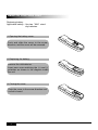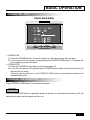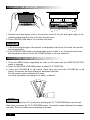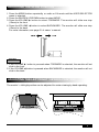
1
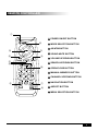
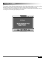
”IN -DASH
MOTORIZED 7”
LCD COLOR MONITOR
WITH AM/FM STEREO RADIO
MODEL: PLR7N
’
OWNER’
S MANUAL
Any changes or modifications in construction of this
device which is not expressly approved by the party
’s
responsible for compliance could void the user’
authority to operate the equipment.
!
WARNING
”are intended
The exclamation point within an equilateral triangle and“WARNING”
to alert the user to the presence of important operating instructions.
Failure to heed the instruction will result in severe injury or death.
DO NOT WATCH VIDEO WHILE DRIVING
Watching the video may distract the driver from looking ahead of the vehicle and cause an
accident.
DO NOT OPERATE ANY FUNCTION THAT TAKES YOUR ATTENTION AWAY FROM
SAFELY DRIVING YOUR VEHICLE
Any function that requires your prolonged attention should only be performed after coming
to a complete stop. Always stop the vehicle in a safe location before performing these
functions. Failure to do so may result in an accident.
DO NOT DISASSEMBLE OR ALTER
Attempts to disassemble or alter may lead to an accident, fire and / or electric shock.
KEEP SMALL ARTICLES OUT OF THE REACH OF CHILDREN
Store small articles (screws etc.) in places not accessible to children. If swallowed, consult
a physician immediately.
USE THE CORRECT AMPERE RATING WHEN REPLACING FUSES
Replace fuses only with fuses of the same ampere rating. Failure to do so may result in a
fire and / or damage to the vehicle.
HALT USE IMMEDIATELY IF A PROBLEM APPEARS
When problems appear, stop using the system immediately and contact the dealer from
whom you purchased the equipment.
1
!
CAUTION
”are intended to
The exclamation point within an equilateral triangle and“CAUTION”
alert the user to the presence of important operating instructions. Failure to heed
the instructions can result in injury or material damage.
DO NOT RAISE THE VOLUME EXCESSIVELY
Keep the volume at a level, where you can still hear outside noises while driving .
Driving while unable to hear outside could cause an accident.
DO NOT USE THIS EQUIPMENT OUTSIDE THE VEHICLE
Do not use this equipment for purposes other than those listed for a vehicle.
Failure to do so may result in an electric shock or an injury.
KEEP FOREIGN OBJECTS OUT OF THE MONITOR COMPARTMENT
Keep foreign objects out of the monitor compartment.
Also, avoid placing your hands in the area where it might interfere with the monitor’s
operation.
STOP THE VEHICLE BEFORE CARRYING OUT ANY OPERATION THAT COULD
INTERFERES WITH YOUR DRIVING.
If the operation of this unit (such as raising or lowering of the monitor, etc.) interferes with
you driving, stop the vehicle in a safe location before attempting operation.
DO NOT MIX NEW BATTERIES WITH OLD BATTERIES. INSERT WITH THE
CORRECT BATTERY POLARITY
Do not mix new batteries with old batteries and do not replace with other than specified
batteries. When inserting the batteries, be sure to observe proper polarity (+ and - ) as
instructed. Battery rupture or chemical leakage can cause an injury or equipment
malfunction.
2
!
CAUTION
”are intended to
The exclamation point within an equilateral triangle and“CAUTION”
alert the user to the presence of important operating instructions. Failure to heed
the instructions can result in injury or material damage.
Operation of some of the functions of this unit is very complex. Because of this, it
was deemed necessary to place these functions into a special SETUP screen. This
will restrict operation of these functions to times when the vehicle is parked. This
ensures the focus of the driver’s attention will be on the road and not on the unit.
This has been done for the safety of the driver and passengers.
TEMPERATURE
Be sure the temperature inside the vehicle is between +60。C (+140。F) and -5。C (+23。F)
before turning your unit on.
FUSE REPLACEMENT
When replacing the fuses, the replacement must be the same amperage as shown on the
fuse holder. If the fuse(s) blow more than once, carefully check all electrical connections
for shorted circuitry. Also have your vehicle’s voltage regulator checked.
MAINTENANCE
If you have problems, do not attempt to repair the unit yourself. Return it to your
purchasing dealer.
INSTALLATION LOCATION
Make sure the unit will not be exposed to :
▶ Direct sun & heat
▶ High humidity
▶ Excessive dust
▶ Excessive vibrations
3
INTRODUCTION
MONITOR
⑩
①
②
⑨ ③
⑤
⑥
⑧
④ ⑦
① POWER ON/OFF BUTTON
② MODE SELECTION BUTTON
③ AS/ATM BUTTON
④ SOUND MUTE BUTTON
⑤ VOLUME UP/DOWN ADJUST BUTTON
⑥ SEARCH UP/DOWN BUTTON
⑦ OPEN/CLOSE BUTTON
⑧ TILT UP/DOWN BUTTON
⑨ BAND SELECTION BUTTON
⑩ MENU SELECTION BUTTON
4
REMOTE CONTROLLER
①
① POWER ON/OFF BUTTON
⑥
⑫
⑤
② MODE SELECTION BUTTON
③ AS/ATM BUTTON
④ SOUND MUTE BUTTON
③
④
②
⑨
⑤ VOLUME UP/DOWN BUTTON
⑥ SEARCH UP/DOWN BUTTON
⑩
⑦ OPEN/CLOSE BUTTON
⑧ MANUAL MEMORY BUTTON
⑨ CHANNEL UP/DOWN BUTTON
⑪
⑦
⑩ NAVIGATION BUTTON
⑧
⑪ ASPECT BUTTON
⑫ MENU SELECTION BUTTON
5
REMOTE CONTROL UNIT
Replacing battery
Applicable battery : Use two“AAA”sized
dry batteries.
1. Opening the battery cover.
Push and slide the cover in the arrow
direction, and the cover will be removed.
2. Replacing the battery.
Remove the old batteries.
Insert new ones matching the (+) and (-)
polarities as shown in the diagram inside
the unit.
3. Closing the cover.
Push the cover in the arrow direction until
a click is heard.
6
BASIC OPERATION
POWER ON / OFF
RADIO MAIN MENU
1. POWER ON
1) Press the POWER button to turn the power on. But the monitor will not open.
2) You can also turn the power on by pressing the OPEN/CLOSE button. The power will
be on and the monitor will open.
2. POWER OFF
1) Press the POWER button again to turn the power off.
2) If you turn the power off by pressing the POWER button when the monitor opens, the
monitor will not close.
If the car key is pulled out, or the OPEN/CLOSE button is pressed the monitor will
automatically close.
OPENING THE MONITOR
Press OPEN/CLOSE button. The monitor will open.
NOTE
If the OPEN/CLOSE button is pressed when the monitor is closed and the power is off, the
monitor will open and the power will turn on.
7
CLOSING THE MONITOR
1. Hold left and right upper side of the monitor and set the left and right angle of the
monitor parallel with the front of the unit as the picture.
2. Press OPEN/CLOSE button. The monitor will close.
NOTE
1. If the left and right angle of the monitor is not parallel to the front of the unit, the monitor
can not be closed.
2. If the OPEN/CLOSE button is pressed while radio or video is on, the monitor will close.
But the sound is still on. Press the POWER button to turn the sound off.
ADJUSTING THE TILT POSITION
1. Press the MENU button repeatedly on radio or AV mode until the USER SELECTOR
menu is selected.
2. Press the SEARCH UP/DOWN button to select TILT POSITION.
3. Press the VOLUME ▶ or ◀ button. Each time you press the VOLUME ▶ or ◀
button, the monitor will slant forward or backward one step.
The tilt position can be adjusted in 5 steps.
For more information, see page 21 of owner’s manual.
70。.110。
NOTE
You can also adjust the TILT position by pushing the TILT UP/DOWN button on the unit.
Each time you press the TILT UP/DOWN button, the monitor slants backward or forward
one step. The tilt position can be adjusted in 5 steps.
8
ADJUSTING THE SLIDE POSITION
1. Press the MENU button repeatedly on radio or AV mode until the USER SELECTOR
menu is selected.
2. Press the SEARCH UP/DOWN button to select MOVE
3. Press the VOLUME ▶ button to select FORWARD. The monitor will slide one step
(15mm) to the front.
4. Press the VOLUME ◀ button to select BACKWARD. The monitor will slide one step
(15mm) to the back.
For more information, see page 21 of owner’s manual.
NOTE
1. If the VOLUME ▶ button is pressed when FORWARD is selected, the monitor will not
slide to the front.
2. If the VOLUME ◀ button is pressed when BACKWARD is selected, the monitor will not
slide to the back.
ADJUSTING THE LEFT/RIGHT VIEWING POSITION
The monitor’s left/right position can be adjusted for easier viewing by hand-operating.
9
SELECTING MODE
Press the MODE button to select the desired mode. Each time you press the button, the
mode changes as follows.
RADIO -> AV1 -> AV2 -> AV3 (CD OR VCD CHANGER) -> AV4 (TV)
NOTE
1. AV3 has only video input.
2. The CD/VCD changer must be connected to the 8 pin DIN socket on the rear of the unit
with 8 pin DIN cable in our CD/VCD changer gift box.
3. The video output of VCD changer must be connected to AV3 video input.
If the video output of VCD changer is not connected AV3 video input, AV3 video input
can be used for video input of other video sources.
ADJUSTING VOLUME
Press the VOLUME ◀
or ▶ button to adjust the volume level.
AUDIO MUTE
Press the MUTE button to make the sound quite. Press the MUTE button again to return
to the previous audio level.
RESET
1. If the unit does not seem to be working right, press the RESET switch with a pencil or
other pointed object. The RESET switch is mounted behind the small hole on the upper
right of the front face, to the left of the AUDIO INPUT hole.
2. If the RESET switch is pressed, the power will be off, press the POWER button to turn
power on.
3. If reset does not solve the problem, consult your installer.
10
ADJUSTING THE TV/VIDEO PICTURE MODE (ASPECT)
Each time you press A (ASPECT) button, the picture mode switches between Normal,
Full, Zoom and Wide.
NORMAL MODE
The monitor displays normal picture at the
center of the screen with the proportion of
4 to 3. The screen shows a vertical black
belt at each side.
FULL MODE
The monitor displays normal picture wider
by stretching out horizontally with the
proportion of 16 to 9.
ZOOM MODE
The monitor displays normal picture wider
by stretching out horizontally and
vertically with the proportion of 4 to 3. The
screen doesn’t show upper and down
part of the picture slightly.
WIDE MODE
The monitor displays normal picture wider
by unevenly stretching out horizontally
with the proportion of 16 to 9. The
stretching proportion is bigger toward
each side of the picture.
NOTE
You can also select the picture mode manually by pressing the function button on the unit
as follows.
1. Press the MODE button to select radio mode.
2. Press the MENU button repeatedly until RADIO SUB MENU is selected.
3. Press the SEARCH UP/DOWN button to select SCREEN.
4. Press the VOLUME ◀ or ▶ button to select the desired picture mode.
11
RADIO CONTROL
Press the OPEN/CLOSE button to turn the power on and to open the monitor. The monitor
shows following picture.
RADIO MAIN MENU
NOTE
1. Each time you press the MENU button on RADIO MAIN MENU screen, the menu on the
screen changes as follows.
RADIO SUB -> VOLUME -> USER SELECTOR -> PICTURE -> RADIO MAIN
2. You can select the items on each menu by pressing the SEARCH UP/DOWN button.
3. You can adjust the level of the selected items by pressing the VOLUME or CH UP
/DOWN button.
MANUAL TUNING
Press the CH UP/DOWN button to move downward or upward one step respectively until
the desired station frequency is selected.
MANUAL STORING OF STATION
1. Tune in the desired radio station you wish to store on the CH number.
2. Press the M(MEMORY) button to store the desired radio station.
The station will be stored into the next CH number of the last CH number previously
stored station.
3. They can be stored up to 30 radio stations in each band.
FM1:30, FM2: 30, AM1:30, AM2:30 stations (total 120 stations).
12
AUTO MEMORY OF STATION
1. Tune in desired radio station you wish to store on the CH number.
2. Press the AS/ATM button for at least 2 seconds. The frequency on the display
continues to change while the auto memory is in progress.
The tuner will automatically seek and can store up to 30 stations in each band in order
of frequency signal. They can be stored in FM1: 30, FM2: 30, AM1: 30 and AM2: 30
stations (total 120 stations).
3. When the auto memory has been completed, the tuner goes to the station stored in the
CH No.1.
NOTE
On CD changer mode, you can pause or playback the current CD by
pressing the AS/ATM button.
TUNING TO THE STORED STATION
Press the SEARCH UP/DOWN button repeatedly until the desired station is selected.
SELECTING THE BAND AREA FOR YOUR COUNTRY
1. Press the MENU button on radio mode. The monitor shows following picture.
RADIO SUB MENU
2. Press the SEARCH UP/DOWN button to select RADIO BAND.
3. When RADIO BAND is selected, press CH UP/DOWN button to select the radio band
area (EUROPE or USA) for your country. Each time you press the CH UP/DOWN
button, the band switches as EUROPE --> USA
13
RADIO BAND
1. Press the SEARCH UP/DOWN button to select RADIO BAND.
2. When RADIO BAND is selected, press the VOLUME ◀ or ▶ button to select the band.
Each time you press the VOLUME ◀ or ▶ button, the band switches as follows.
FM1 -> FM2 -> AM1 -> AM2
3. You can also select the band by pushing the BAND button on the unit.
Each time you press the BAND button, the band switches as follows.
FM1 -> FM2 ->AM1 -> AM2
TREBLE
1. Press the SEARCH UP/DOWN button to select TREBLE.
2. Press the VOLUME ◀ or ▶ button to adjust treble level.
BASS
1. Press the SEARCH UP/DOWN button to select BASS.
2. Press the VOLUME ◀ or ▶ button to adjust bass level.
SUB WOOFER
1. Press the SEARCH UP/DOWN button to select SUB WOOFER.
2. Press the VOLUME ◀ or ▶ button to adjust sub woofer level.
LOUDNESS
1. Press the SEARCH UP/DOWN button to select LOUD.
2. Press the VOLUME ◀ or ▶ button to adjust loudness level.
14
NAVIGATION
SETTING THE NAVIGATION
1. Connect a NAVIGATION system only to AV1 or AV2 Input terminals on the rear of the unit.
2. Press the MODE button to select radio mode.
3. Press the MENU button to select following picture.
RADIO SUB MENU
4. Press the SEARCH UP/DOWN button to select NAVIGATION.
5. Press the VOLUME ◀ or ▶ button to select AV1 or AV2 that NAVIGATION system
is connected to.
Each time you press this button, AV Input changes as follows
AV 1 -> AV2 -> OFF
WATCHING THE NAVIGATION PICTURE
Press the NAVI button on radio, AV1, 2 or 3 mode. The monitor shows the navigation
picture.
NOTE
Do not select the AV mode connected to the NAVIGATION system with
the MODE button. If AV Input connected to the NAVIGATION system is
selected with the MODE button, the monitor does not show the
NAVIGATION picture. The monitor shows the WARNING picture.
15
CAMERA IN
SETTING THE CAMERA IN
1. Connect a Back View Camera video output only to AV1,2 or 3 video Input terminals on
the rear of the unit.
* When the VCD changer is connected to AV3 Video input, The back view camera can
be connected only to AV1 or AV2 video input.
2. Press the MODE button to select radio mode.
3. Press the MENU button to select following picture.
RADIO SUB MENU
4. Press the SEARCH UP/DOWN button to select CAMERA IN.
5. Press the VOLUME ◀ or ▶ button to select AV1,2 or 3 mode that Back View
Camera is connected. Each time you press this button, AV Input changes as
AV1 -> AV2 -> AV3 -> OFF
WATCHING THE BACK VIEW PICTURE
Set the rear gear on any mode. The monitor shows the back view camera picture.
WIRING CONNECTION
Connect orange color connection wire named “REVERSE GEAR” to a switched power
output terminal of the R (reverse) gear.
See page 26: BASIC CONNECTIONS.
NOTE
16
If AV input connected to the Back view Camera is selected with the MODE
button, the monitor does not show the back view camera picture.
The Monitor shows only the WARNING picture.
CD CHANGER CONTROL
When a CD (VCD) changer is connected to this unit with 8 pin DIN cable, AV3 mode
changes to CDC mode and CDC control menu is displayed on the screen.
1. Press the MODE button to select CD CHANGER (AV3) mode.
Each time you press this button, the display changes as follows.
RADIO-> AV1-> AV2-> AV3 (CD or VCD CHANGER) -> AV4(TV)
2. When CD CHANGER (AV3) mode is selected, The monitor shows following picture.
3. Press the SEARCH UP/DOWN button to select the item.
4. Press the CH UP/DOWN button to adjust the level of the selected item. You can also
adjust the level upward by pushing the BAND button on the unit.
NOTE
1. Each time the MENU button is pressed on CDC mode, the menu on the screen changes
as follows.
CD CHANGER -> VOLUME -> USER SELECTOR -> PICTURE -> OSD OFF
2. The CD (VCD) changer must be connected to the 8pin DIN socket on the rear of the
unit with the 8pin DIN cable in our CD/VCD changer gift box.
3. The video output of VCD changer must be connected to AV3 video input.
CD STATUS
This shows the current CD status (DISC CHECK, SEEK, PLAY, ETC)
PLAY TIME
This shows playing time of the disc being played.
DISK NUMBER
1. Press the SEARCH UP/DOWN button to select DISC NUMBER.
2. Each time you press the CH UP button, the disc in the CD changer
will be selected forward and the displayed disc number increases by one.
3. Each time you press the CH DOWN button, the disc in the CD changer
will be selected backward and the displayed disc number decreases by one.
17
TRACK NUMBER
1. Press the SEARCH UP/DOWN button to select TRACK NUMBER.
2. Each time you press the CH UP button, the next track number will be selected forward
and the displayed track number increases by one.
3. Each time you press the CH DOWN button, the previous track number will be selected
and the displayed track number decreases by one.
INTRO SCAN
1. Press the SEARCH button to select INTRO SCAN.
2. Press the CH UP/DOWN button to select the item.
Each time you press the CH UP/DOWN button or the BAND button, the item changes
as ONE -> ALL -> OFF
ALL : The first 10 seconds of first track of all the discs will be played in succession.
ONE : The first 10 seconds of each track of the selected disc will be played in succession.
OFF : INTRO SCAN will be off.
REPEAT
1. Press the SEARCH button to select REPEAT.
2. Press the CH UP/DOWN button or the band button to select the item. Each time you
press the CH button, the item changes as ONE -> ALL -> OFF
ALL : All the tracks on the current disc will be played repeatedly.
ONE : The selected track on the current disc will be played repeatedly.
OFF : REPEAT will be off.
RANDOM
1. Press the SEARCH UP/DOWN button to select RANDOM .
2. Press the CH UP/DOWN button or the BAND button to select the item.
Each time you press the button, the item changes as ONE -> ALL -> OFF
ALL : The tracks on all the discs in the CD/VCD changer will be played in random order.
ONE : All the tracks on the current disc will be played in random order.
OFF : RANDOM will be off.
PAUSE
Press the AS/ATM button to pause playback. Press the button again to resume playback.
18
DIRECT CD CHANGER CONTROL
On the CD changer mode, you can directly control CD changer functions just by pressing
the buttons on the remote controller for our monitor unit.
STOP ■ button
PAUSE button
PLAY
REW
button
button
FF
button
DISC + button
DISC -
button
TRACK+button
TRACK - button
: to make the playing of the disc stop.
: to stop the playing of the disc .
press again to play again.
: to make the disc play.
: to quickly move backward of the disc until you reach
the desired section of the track.
: to quickly move forward of the disc until you reach
the desired section of the track.
: to search forwards through the discs in a CD changer
until you reach the desired disc.
: to search backwards through the discs in a CD changer
until you reach the desired disc.
: to search forwards through the tracks on the disc
until you reach the desired track.
: to search backwards through the tracks on the disc
until you reach the desired track.
NOTE
1. The AS/ATM button on the remote controller can be used as the PAUSE button.
2. When the CD changer mode is selected again after switching the CD changer mode to
other modes or the power of the monitor unit is tuned on again after tuned it off, the
disc plays at the last played position.
3. When the ignition is switched on again after the car key is pulled out on CD changer
mode, the disc plays at the beginning of the track last played.
19
VOLUME ADJUSTMENT OF EACH CHANNEL
You can adjust the volume level of each channel of the radio or AV sources connected to
this unit.
ADJUSTING THE VOLUME OF EACH CHANNEL
1. Press the MENU button repeatedly on radio or AV mode until VOLUME MENU is selected
The monitor shows following picture.
VOLUME MENU
2. Press the SEARCH UP/DOWN button to select the audio channel that you want to
adjust.
3. Press the VOLUME ◀ or ▶ button to adjust the volume level of the selected audio
channel.
DEFAULT
1. Press the SEARCH UP/DOWN button to select DEFAULT.
2. Press the VOLUME ◀ or ▶ button to select ON or OFF.
Each time you press the VOLUME ◀ or ▶button, the display changes as follows.
ON -> OFF
20
FINE ADJUSTMENT FOR CENTER FREQUENCY
AND TILT/SLIDE POSITION
1. Press the MENU button when the monitor shows following picture.
VOLUME MENU
The monitor shows following picture.
USER SELECTOR MENU
USER SELECTOR
TILT POSITON
MOVE
0
FORWARD
2. Press the SEARCH UP/DOWN button to select the items that you want to adjust.
3. Press the VOLUME ◀ or ▶ button to adjust the level of the selected item.
21
SCREEN CONTROL
1. Press the MENU button when the monitor shows following picture.
USER SELECTOR MENU
USER SELECTOR
TILT POSITON
MOVE
0
FORWARD
The monitor shows following picture.
PICTURE MENU
2. Press the SEARCH UP/DOWN button to select the items that you want to adjust.
3. Press the VOLUME ◀ or ▶ button to adjust the level of the selected item.
22
SELECTING COLOR/SOUND SYSTEM
1. Press the SEARCH UP/DOWN button to select COLOR SYSTEM for the video source
on PICTURE menu.
PICTURE MENU
2. Press the VOLUME ◀
or ▶ button to select PAL or NTSC for the video source.
NOTE
To select the color system for the TV when the TV tuner box is connected to the AV4 input
of this unit,
1. Select color system (PAL or NTSC) for the video source at COLOR SYSTEM on
PICTURE menu on radio mode first.
2. Select color and sound system again at COLOR SYSTEM on FUNCTION menu on TV mode.
For more information, see page 5 & 6 “COLOR & SOUND SYSTEM”in owner’s manual
for the TV tuner.
NOTE
If the monitor displays the picture in black & white color, select the color system again for
the video source.
23
VOLUME CONTROL ON AV MODE
To adjust audio level of AV sources on AV mode,
1. Press the VOLUME ◀ or ▶ button.
The monitor shows following picture.
2. Press the SEARCH UP/DOWN button to select the items that you want to adjust.
3. Press the VOLUME ◀ or ▶ button to adjust the audio level of the selected item.
NOTE
1. Each time the MENU button is pressed on AV1, 2 or 3 mode, the menu is selected as
follows.
VOLUME -> USER SELECTOR -> PICTURE
2. You can select the items on each menu by pressing the SEARCH UP/DOWN button.
3. You can adjust the level of the selected items by pressing the VOLUME ◀ or ▶ button.
24
WARNING SCREEN
The monitor shows following warning picture when the parking brake is not set or when
driving to prevent traffic accident that may be caused while watching the screen.
The monitor shows the warning picture only and does not show any other pictures, but you
can enjoy the sound only by adjusting the volume.
25
AV INPUT FACE PLATE OF THE UNIT
Video
Audio
Yellow : Video
White : Audio Left
Red : Audio Right
Front View
NOTE
26
3.5 Ø AV input on the front face of the unit is same input with AV1 input
on the rear of the unit. If the sources are connected both input
terminals,the 3.5Ø input has priority in working.
INSTALLATION
PRECAUTIONS
Choose the mounting location carefully so that the unit will not interfere with the normal
driving functions of the driver.
Avoid installing the unit where it would be subject to high temperatures, such as from
direct sunlight or hot air from the heater, or where it would be subject to dust, dirt or
excessive vibration.
Use only the supplied mounting hardware for a safe and secure installation.
Be sure to remove the front panel before installing the unit.
Mounting angle adjustment
Adjust the mounting angle to less than 20。.
MOUNTING EXAMPLE
Installation in the dashboard
Convenient spot
on the fire wall
Metal
Mounting Strap
Tapping Screw
3
Strap
Be sure to use the strap to secure
the back of the unit in place to
prevent sound cuts or skips.
The strap can be bent by hand to the
desired angle.
Holder
After inserting the holder into the
dashboard, select the appropriate
tabs according to the thickness of the
dashboard material and bend them
inwards to secure the holder in place.
How to Detach the Mounting
Frame
1. Insert release keys into the slots A.
2. Remove the frame B from the unit.
Keep the release key in the safe
place as you may need it in the future
to remove the unit from the car.
A
2
B
2
NOTE : Keep the release keys in the
safe place as you may need if in the
future to move the unit from the car.
27
BASIC CONNECTIONS
REMOTE TURN-ON
(Blue/White)
To amplifier or equalizer
AUTO ANT
(Blue)
To power antenna
PARKING BRAKE
(Brown)
To the parking brake signal lead
ACC
(Red)
(Yellow)
BATTERY (MEMORY)
(Black)
(Orange)
Ignition Key
GROUND
REVERSE GEAR
-
+
Battery
SPEAKER
REAR
LEFT
SPEAKER
FRONT
LEFT
+
(Gray/Black)
(Violet/Black)
Front right
-
(Violet)
(Green)
Rear right
+
Speakers
(Green/Black)
(White/Black)
Rear left
-
SPEAKER
REAR
RIGHT
(Gray)
+
SPEAKER
FRONT
RIGHT
(White)
Front left
+
NOTE
28
1. Be sure that the PARKING SENSOR WIRE must be grounded or
opened. If it is connected to ACC (B+). The unit can be damaged.
2. Do not ground the POWER ANTENNA or REMOTE TURN ON wire.
If it is grounded, the unit can be damaged.
Ext. AV 1
Yellow
White
Red
Sub Woofer
Rear Left
Rear Right
Front Left
Front Right
Video
Left
Right
AV-1 INPUT
Yellow
White
Red
White
Red
PRE AMP RCA LINE OUT
ANT.
TV Tuner Box
4PIN DIN
CD (VCD)
Changer
4PIN DIN
Video in
(Yellow)
V 3 INPUT
Red
White
Right
Left
AV4 Input
TV Tuner Input
Yellow
Video
Video out
(Yellow)
8P Din
16P Connector
VIDEO in
Ext. Monitor
Yellow
Yellow
Video
VIDEO out
White
Red
Left
Right
AV2 INPUT
Ext. AV 2
CONNECTING TO CD CHANGER AND TV TUNER BOX
YELLOW
WHITE
RED
29
SPECIFICATIONS
AM SECTION
USA BAND Frequency Range
Frequency Step
EUROPE BAND Frequency Range
Frequency Step
Intermediate Frequency
Usable Sensitivity
Image Rejection Ratio
IF Rejection Ratio
530-1710KHz
10KHz
522-1620KHz
9KHz
450 KHz
32 dB
45dB
100dB
FM SECTION
Frequency Range
Frequency Step Manual tuning
Seek tuning
Intermediate Frequency
Usable Sensitivity
Image Rejection Ratio
IF Rejection Ratio
87.5~108 MHz
50 KHz
100KHz
10.7MHz
12dB
45dB
60dB
CD CHANGER
Signal/Noise Ratio
Frequency Response
Channel Separation
D/A Converter
›80dB
20kHz - 20kHz
›60dB
16Bit/CH
AMPLIFIER
Total Max Power
Power Output
200 Watts peak
50W X 4
GENERAL
Power Supply
Polarity
Speaker Impedance
Fuses
Dimensions
Weight
Net
Gross
.DC 14.4V (11V - 15V)
Negative Ground only
4~8Ω
Fast blow (1A and 10A)
178(W)x 50(H)x 155(D)mm
2.5Kg
3.5Kg
30
Printed In Korea