1
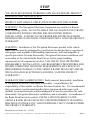
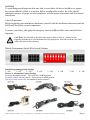
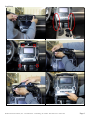
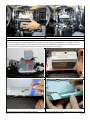
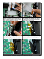
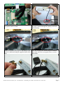
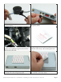
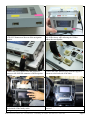
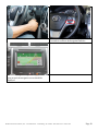
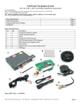
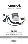
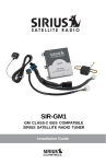
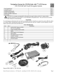
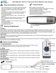
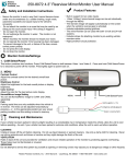
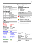
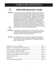
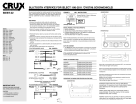
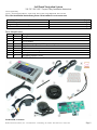
SoftTouch Navigation System
250-7613 2012-2013 Toyota Camry Installation Instructions
General Applicability:
Toyota – 2012-2013 Prius/Prius V, 2013 Venza, 2013 Avalon, 2013 Highlander, 2013 Tacoma
For video installation instructions, please visit us online at www.rostra.com.
Parts Identification
Vehicle Preparation
Programming Switch Settings
Installation
Page 1
Page 3
Page 3
Page 4
Parts Identification
Item
1
2
3
4
5
6
7
8
9
10
Qty.
1
1
1
1
1
1
1
1
1
1
Description
Navigation interface module
LCD IN harness
TP-IN harness
Hardware service parts (VHB tape, metal plate)
Vehicle interface harnesses
Stylus
GPS antenna with magnetic base
GPS speaker
Navigation interface board
LCD-IN/TP-IN Extension Harness
Form #5420, 3-20-2013
Rostra Precision Controls, Inc. - 2519 Dana Dr. - Laurinburg, NC 28352 - 800-782-3379 - rostra.com
Page 1 STOP
YOU MUST READ THESE WARNINGS AND NOTICE BEFORE PRODUCT
HANDLING AND INSTALLATION!
PRODUCT AND VEHICLE APPLICATION WARRANTY DISCLAIMER
WARNING ! The Navigation Electronic Components are sensitive to ElectroStatic Discharge (ESD). DO NOT HANDLE THE NAVIGATION ELECTRONIC
COMPONENTS WITHOUT PROPER ESD GROUNDING DURING
INSTALLATION. FAILURE TO USE PROPER ESD PROTECTION WHEN
HANDLING THE NAVIGATION COMPONENTS WILL VOID THE PRODUCT
WARRANTY.
WARNING ! Installation of this Navigation Electronics product in the vehicle
radio head unit must be performed by a professional technician that is experienced
with proper work methods, ESD handling requirements, and knowledgeable of
specific procedures for radio disassembly, Navigation Electronics installation, and
re-assembly of the vehicle Radio Head Unit as well as proper handling
requirements of all components involved. FAILURE TO FOLLOW PROPER
DISASSEMBLY, INSTALLATION, AND REASSEMBLY PROCEDURES AND
PROPER COMPONENT HANDLING REQUIREMENTS MAY RESULT IN
IRREVERSIBLE DAMAGE TO THE VEHICLE RADIO HEAD UNIT AND/OR
THE NAVIGATION ELECTRONICS AND WILL VOID THE PRODUCT
WARRANTY!
WARRANTY DISCLAIMER NOTICE! Radio removal, disassembly, installation
of Navigation Electronics, and Radio re-assembly / re-installation is the
responsibility of the installer, not Rostra Precision Controls, Inc. It is recommended
that you contract a professional installer that is experienced with proper work
methods involving electronics and knowledgeable of specific procedures for radio
disassembly, Navigation Electronics installation, and re-assembly / re-installation of
the Radio Head Unit in the vehicle. INSTALLATION DAMAGE TO THE
VEHICLE RADIO HEAD UNIT IS NOT THE RESPONSIBILITY OF ROSTRA
PRECISION CONTROLS, INC. AND IS EXPRESSLY NOT COVERED UNDER
THE PRODUCT WARRANTY.
Rostra Precision Controls, Inc. 2/5/2013
Rostra Precision Controls, Inc. - 2519 Dana Dr. - Laurinburg, NC 28352 - 800-782-3379 - rostra.com
Page 2 WARNING
To avoid dangerous distractions that may lead to an accident, the driver should never operate
the system while the vehicle is in motion. Before installing this product, the seller should
inform the end-user of proper use and compliance with the proper instructions and all state and
federal laws.
Vehicle Preparation
Before beginning your installation, familiarize yourself with the installation instructions and the
SoftTouch Navigation system components.
To ensure your safety, (A) apply the emergency brake and (B) read this entire manual before
beginning.
CAUTION: It is advisable to disconnect the negative battery cable for 3 minutes before
beginning installation, to avoid unintended air bag deployment. Note and record any anti- theft
radio codes prior to disconnecting.
Default Programming Switch (Dip Switch) Settings
Default Programming Switch Settings
1 – Off
2 – Off
3 – Off
4 – Off
5 – Off
Factory or Aftermarket Camera Settings
To use an aftermarket camera – Place switch #1 in OFF position.
To use the vehicle’s factory camera – Place switch #1 in ON position.
Visit www.rostra.com to view all compatible backup cameras!
6 – Off
Rostra Precision Controls, Inc. - 2519 Dana Dr. - Laurinburg, NC 28352 - 800-782-3379 - rostra.com
7 – Off
8 – Off
Page 3 Installation
Remove air vent to access upper radio screws.
Remove trim pieces to access lower screws.
Remove four screws securing radio/screen unit.
Release connectors from upper dash trim.
Remove upper dash trim from radio.
Gently tilt radio away from dashboard.
Rostra Precision Controls, Inc. - 2519 Dana Dr. - Laurinburg, NC 28352 - 800-782-3379 - rostra.com
Page 4 Release harnesses from rear of radio/screen.
Navigation Interface Module Installation
Lift screen away from dashboard.
ESD Warning: Do not handle the navigation interface circuitry without taking proper electrostatic discharge
precautions making sure both the installer and navigation unit are properly grounded before touching any interior
radio or navigation components. The warranty on this product is immediately voided if these precautions are not
taken and the navigation unit and/or radio are damaged due to electrostatic discharge.
Remove radio brackets from each side.
Use a trim tool to release the screen tabs and then
lift the housing to access the radio’s interior.
Remove screws securing the screen housing.
Remove the backing from the double-sided tape of
the nav board and secure it to the metal cover below
Rostra Precision Controls, Inc. - 2519 Dana Dr. - Laurinburg, NC 28352 - 800-782-3379 - rostra.com
Page 5 Installer note: To gain more flexibility while
installing the navigation interface board in the next
steps, you can release the tabs to remove the ribbon
cables attached the main body to the screen.
Disconnect the large brown ribbon cable from the
factory board and insert the ribbon cable from the
nav interface board. Then insert the brown ribbon
cable into the nav interface board.
Disconnect the small brown ribbon cable from the
factory board and insert the ribbon cable from the
nav interface board. Then insert the brown ribbon
cable into the nav interface board.
Place one of the included ESD tape strips over any
exposed metal underneath the small navigation
interface board.
Place the second ESD tape strip over nav board.
Use included cloth tape over ESD tape to secure it.
Rostra Precision Controls, Inc. - 2519 Dana Dr. - Laurinburg, NC 28352 - 800-782-3379 - rostra.com
Page 6 Connect LCD-IN/TP-IN Extension Harness to the
navigation interface board.
Route the LCD-IN/TP-IN Extension Harness from
the radio’s interior through the opening in the back
of the housing.
Attach the included metal plate to the interior of the
vehicle’s dashboard using the supplied double-sided
tape.
Place the included GPS antenna atop the mounted
metal plate and allow its magnetic base to secure it
to the plate.
Located the threaded connector of GPS antenna.
Thread GPS antenna onto navigation module.
Rostra Precision Controls, Inc. - 2519 Dana Dr. - Laurinburg, NC 28352 - 800-782-3379 - rostra.com
Page 7 Connect the included speaker to the speaker
extension harness.
Connect the speaker extension harness to the
navigation module.
Using the supplied cable ties, mount the navigation
speaker to the dashboard support brackets behind
and below the radio unit.
Using the supplied alcohol pad, throughly clean the
underside of the factory radio and navigation unit.
Once clean, press the supplied VHB tape firmly to
the bottom side of the navigation module.
Peel the protective layer from the VHB tape making
sure no debris comes into contact.
Rostra Precision Controls, Inc. - 2519 Dana Dr. - Laurinburg, NC 28352 - 800-782-3379 - rostra.com
Page 8 Connect the yellow and pink color-coded TP-IN and
LCD OUT harnesses to the rear of the navigation
module.
Firmly press the navigation module to the bottom
side of the factory radio allowing the VHB to
adhere the two together.
Connect the power harness from the supplied tharness to the POWER connector of the navigation
module.
Connect the radio interface plug from the supplied
t-harness to the backside of the radio.
Reconnect all previously disconnected harness from
the backside of the factory radio.
Navigation System Testing
Radio component replacement is the reverse of
removal.
Rostra Precision Controls, Inc. - 2519 Dana Dr. - Laurinburg, NC 28352 - 800-782-3379 - rostra.com
Page 9 Turn on the vehicle’s ignition.
Press the steering wheel’s phone hang up button for
2 seconds to switch to the navigation interface.
Once the steering wheel’s phone hang up button has
been pressed, the navigation screen should be
displayed.
Rostra Precision Controls, Inc. - 2519 Dana Dr. - Laurinburg, NC 28352 - 800-782-3379 - rostra.com
Page 10