1
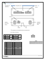
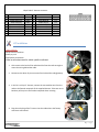
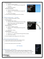
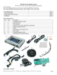
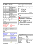
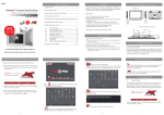
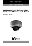
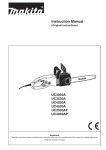
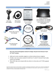
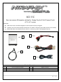
UCI-11C
Rear view camera & Navigation solution for Dodge, Chrysler & Fiat UConnect Touch
4.3” & 8.4” systems
Overview:
Adds touch screen controlled navigation to vehicles without factory navigation
Provides a rear view camera solution for both the 4.3” and 8.4” UConnect Touch radios (camera not included)
Allows DVD video to be viewed while the vehicle is in drive (only on 8.4” DVD equipped systems)
3
1
.
4
2
5
1
2
3
UCI-11C interface module
LVDS cable
Video IN cable
Product Description
4
5
Radio T-harness
USB update cable
1|Page
Connectorpin out
Navigation/AV
(reserved)
Radio THarness
USB (update port)
Hh
Video IN
LVDS OUT
(to screen
Black)
LVDS IN
(from radio
White)
LED
Activity
LED
N/A
* The connectors are viewed from the wire insertion side
8 Pin Video IN Connector
1
Shield
RCA 3
Shield
RCA
5 Video Signal
7 Video Signal
2
Shield
RCA 4
Video +
Twisted
Pair
6 Video Signal
8
Video 24 pin Navigation Connector
1
2
3
4
5
6
7
8
9
10
11
12
+12V OUT
Acc OUT
RX IN
EMPTY
RGB BLUE IN
RGB GREEN IN
RGB RED IN
RGB SYNC IN
EMPTY
EMPTY
EMPTY
EMPTY
13
14
15
16
17
18
19
20
21
22
23
24
Ground OUT
Mute IN
TX OUT
EMPTY
EMPTY
EMPTY
EMPTY
EMPTY
EMPTY
Audio Ground IN
Audio Left IN
Audio Right IN
2|Page
18 pin Radio T-Harness connector
1
+12v Power
10
Ground
2 Audio Ground OUT
Radio 11
Audio Ground IN
3
Audio Right OUT
Radio 12
Audio Right IN
4
Audio Left OUT
Radio 13
Audio Left IN
5
1A 12v OUTPUT
OUT 1 14
1A 12v OUTPUT
6 Infotainment CAN HI Radio 15 Infotainment CAN LO
7 Infotainment CAN HI Screen 16 Infotainment CAN LO
8
Vehicle CAN HI
Car
17
Vehicle CAN LO
9
Vehicle CAN HI
Radio 18
Vehicle CAN LO
Car
Car
Car
OUT 2
Radio
Screen
Car
Radio
UCI Installation
TOOLS REQUIRED
Phillips head screwdriver
Plastic pry tool
Small pocket screwdriver
*Refer to online document for vehicle specific installation*
1. Gain access to the back of the radio head. Pull out the radio enough to
access the wiring behind the radio.
2. Disconnect the white 22 pin connector from behind the radio/gateway.
3. In the kit is a 22 pin T-harness, connect the removed harness from the
radio to the female receptacle of the supplied harness. Take care not to
bend any of the pins in the female receptacle when inserting.
4. Plug the male plug of the T-harness into the radio where the factory
connector was located.
3|Page
5. Gain access to the rear of the screen & disconnect the 3 cables that are attached.
6. Set the unit aside for ease of installation of the UCI.
7. The free end of the 22 pin T-harness that is plugged into the radio head, is routed behind the dash to the screen
location.
8. The 18 pin connector is inserted into the port labeled “Radio T-harness”.
9. Locate the WHITE, ROUND connector that was removed from the screen. Insert this cable into the WHITE port
labeled “LVDS IN”.
10. Take the provided LVDS cable and insert the BLACK end into the BLACK port (LVDS OUT). The other end will be
connected to the screen later.
11. If installing a rear view camera, insert the 8 pin MOLEX plug into the port labeled “Video IN”. Of the connections
available, there’s;
a. Twisted Pair – Used for factory installed camera only on the 4.3” screens. This input is not used on the
8.4” screens. On the 8.4” screens, the factory camera input is on the back of the radio head.
b. Video 1, 2 & 3- Used for an aftermarket camera input using composite video (yellow RCA connection).
*Power connections for therear view camera can be made at the cigarette lighter.
12. If installing navigation into the system, proceed to the navigation installation section. Otherwise continue to
step 13.
13. After all the connections are made, securely mount the UCI module in the dash.
14. Connect the WHITE end of the provided LVDS cable into the screen. Make all other connections and reassemble
the radio/screen.
15. Make the necessary changes in the SETUP menu & test.
16. Using the plastic pry tool, gently pry around the dash panel to release the locking tabs. Take extra care when
releasing these tabs, they may fall from the dash panel and into the dash.
If Installing Directus Navigation
Once you complete step 12 of the UCI installation, continue from this point.
1. Plug in the supplied 24 pin Navigation harness into the port labeled NAVIGATION/AV.
2. Route this cable down to the driver’s side under dash or any location that is secure. Be sure to securely fasten it
to existing wiring and brackets. Route away from any sharp or moving parts.
3. Using Velcro, secure the module. For added stability, a large zip tie should be used to secure the module in
place.
4. Plug the routed cable from the UCI into the
Directus navigation unit.
a. Black Din - RGB
b. Grey Din – DATA
c. 4-pin MOLEX – DC IN
NOT USED
5. Included in the kit is an external speaker, it is used for turn by turn navigation or any audio output from the
navigation unit. The speaker can be mounted on one of the metal rails running vertically under the steering
column. It is recommended that the speaker faces the opening under the steering column for best volume.
6. Plug the speaker into the 3.5mm jack labeled SPK on the navigation.
4|Page
7. The GPS antenna needs to be installed, right side up, in a location that has a clear line of sight of the sky. The
antenna can be mounted on the dash, or located in the dash below the dash pad without any metal
obstructions. Be sure the antenna is securely mounted with Velcro, 2 sided stick tape or onto a metal surface.
8. Connect the antenna to the jack labeled GPS ANT on the navigation unit.
9. Return to step 13 in the UCI installation instructions above.
.
Settings
4.3” Monitor
Adjusting the rearview camera settings
To access the settings screen, press and hold the “Settings” button for 3 seconds.
On the touch screen, select “Camera Input Settings”.
Adjusting the input:
o Touch the “Input” soft key
o Every press of the icon will change the input: OFF, DIFF
(factory camera), Video 1, Video 2, Video 3. The input
image will be displayed in the back ground.
Adjusting brightness:
o Touch the “Brightness” soft key.
o Press the “-“or “+” soft key to adjust the image in 10%
increments.
o Press the “Exit” soft key.
5|Page
Adjusting Contrast:
o Touch the “Contrast” soft key.
o Press the “-“or “+” soft key to adjust the image in 10%
increments.
o Press the “Exit” soft key.
Adjusting the Saturation:
o Touch the “Saturation” soft key.
o Press the “-“or “+” soft key to adjust the image in 10%
increments.
o Press the “Exit” soft key.
To exit the Camera Input Setting, press the “Exit” soft key.
Adjusting the navigation settings (if installed)
Press the “Navigation input settings” soft key.
Adjusting the input:
o Touch the “Input” soft key
o Every press of the icon will change the input: OFF, RGB,
Video 1, Video 2, Video 3. The input image will be
displayed in the back ground.
Adjusting brightness:
o Touch the “Brightness” soft key.
o Press the “-“or “+” soft key to adjust the image in 10%
increments.
o Press the “Exit” soft key.
Adjusting Contrast:
o Touch the “Contrast” soft key.
o Press the “-“or “+” soft key to adjust the image in 10% increments.
o Press the “Exit” soft key.
To exit the Navigation input setting, press the “Exit” soft key.
To view the current hardware/software revision
Press the “About” soft key to show current software revision.
Press the “Exit” soft key to return to the main menu.
To return to the system, press the “Exit” soft key.
8.4” Monitor
Adjusting the rearview camera settings
To access the settings screen, Press and hold the radio power button for 3 seconds.
*If the vehicle has a factory camera, set the Camera input to “HEAD UNIT”. All setting s
for the factory camera can be changed in the factory, not the UCI, “Settings” menu.
6|Page
On the touch screen, select “Camera Input Settings”.
Adjusting the input:
o Touch the “Input” soft key
o Every press of the icon will change the input: OFF, Head Unit (factory camera),
Video 1, Video 2, Video 3. The input image will be displayed in the back ground. (If
the radio is set for Head Unit, the camera adjustments are accessed in the factory
menu).
Adjusting brightness:
o Touch the “Brightness” soft key.
o Press the “-“or “+” soft key to adjust the image in 10% increments.
o Press the “Exit” soft key.
Adjusting Contrast:
o Touch the “Contrast” soft key.
o Press the “-“or “+” soft key to adjust the image in 10% increments.
o Press the “Exit” soft key.
Adjusting the Saturation:
o Touch the “Saturation” soft key.
o Press the “-“or “+” soft key to adjust the image in 10% increments.
o Press the “Exit” soft key.
To exit the Camera Input Setting, press the “Exit” soft key.
Adjusting the navigation settings (if installed)
Press the “Navigation input settings” soft key.
Adjusting the input:
o Touch the “Input” soft key
o Every press of the icon will change the input: OFF & ON. Only the RGB input is
available. The input image will be displayed in the back ground.
Adjusting brightness:
o Touch the “Brightness” soft key.
o Press the “-“or “+” soft key to adjust the image in 10% increments.
o Press the “Exit” soft key.
Adjusting Contrast:
o Touch the “Contrast” soft key.
o Press the “-“or “+” soft key to adjust the image in 10% increments.
o Press the “Exit” soft key.
To exit the Navigation input setting, press the “Exit” soft key.
Changing the Video in motion settings
Press the “Video in Motion” soft key.
o Touch the “Video in Motion” soft key to change status: ON or OFF
This function enables and disables the ability to watch DVD videos while
the vehicle is in drive.
o Press the “Exit” soft key to return to the main menu.
7|Page
To view the current hardware/software revision
Press the “About” soft key to show current software revision.
Press the “Exit” soft key to return to the main menu.
To return to the system, press the “Exit” soft key.
* Note: Changes in the settings menu will not be saved until “Exit” is pressed. Changes will not be saved if the
ignition is cycled before the “Exit” soft key is pressed.
Operation
Rear View Camera
The rear view surroundings will be displayed anytime the vehicle is shifted into REVERSE. The image will be
displayed on the factory touch screen along with the text “Check Entire Surroundings”. The text will remain on the
screen for 10 seconds and then will fade out. Once the vehicle is shifted out of REVERSE, the image will fade into the
previous mode or screen. Do not rely completely on the rear camera image; periodically check your surroundings for
obstacles.
Navigation
4.3” monitor
To display navigation, press the “Screen Off” button. This will display the navigation home page. To exit
navigation press the Screen Off button again. Audio prompts will be heard through the external speaker. Refer to the
navigation documentation for operation.
8.4” monitor
When navigation is enabled, a new icon will show up in the bottom right corner of the screen, where the “More”
soft key is located. To access the navigation, press the “Nav” soft button on the lower right corner. The navigation
screen will be displayed. All the functions of the navigation can be controlled through the factory touch screen. (Refer
to the user manual for operation). To exit the navigation screen, press the desired source. The “More” soft touch button
for the factory SETTINGS screen can be accessed through the navigation screen. While in navigation mode, if the climate
control is adjusted the navigation screen will disappear anytime the system is being accessed. 3 seconds after the last
operation, the navigation screen will return.
8|Page
FAQ:
Q. When the vehicle is in reverse, I get a blank screen.
A. Verify that whatever input the camera is connected to, i.e. video 1, which is what is selected in the “Camera Settings
Input”. If the wrong input is selected, there will not be an image.
Q. When the vehicle is in reverse, the camera image is garbled and flickers.
A. The camera is insufficiently powered. The common cause is the camera is powered from the reverse lamps. It is
recommended to make the power connections at the cigarette lighter.
Q. When I change the settings in the UCI menu, they’re not being saved.
A. To save the changes in the settings menu, the “Exit” icon needs to be used to exit the menu. Any other way of exiting
the menu will not save the settings.
Q. When I display the navigation screen, the image isn’t displayed properly. ie. garbled or skewed.
A. On the Kenwood navigations, verify the Blue/Black wire in position 12, is cut for a 4.3” screen or intact for an 8.4”
screen.
The Directus units are preconfigured for a specific screen size. Verify that the correct navigation unit is being installed
for the particular screen in the vehicle. These units cannot be user configured.
9|Page