1
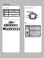
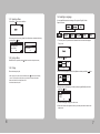
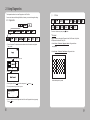
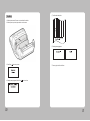
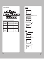
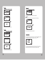
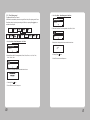
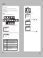
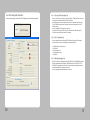
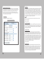
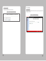
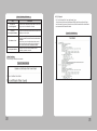
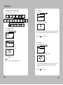
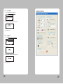
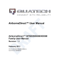
SEWOO TECH CO.,LTD.
374-2, Gajang-dong, Osan-si, Gyeonggi-do, 447-210, Korea
TEL : +82-31-459-8200 FAX : +82-31-459-8880
www.miniprinter.com
MODEL:LK-P43
Portable Printer
System Administrator Manual
P43 Rev. A 05/13
Table of Contents
1. INTRODUCTION
4
1-1 Using This Manual
4
1-2 Using the Menu Chart
4
1-3 Using the Display and Buttons
5
1-3-1 Selecting a Menu
6
1-3-2 Exiting a Menu
6
1-3-3 Printing
6
1-4. Selecting a Language
2. USING DIAGNOSTICS
2-1 Diagnostics
7
8
8
2-1-1 Printer
9
2-1-2 Display
15
2-1-3 Buttons
16
2-1-4 RAM
17
2-1-5 Data Dump
18
2-1-6 About
19
3. SETTING UP THE PRINTER
3-1 SETUP
20
20
3-1-1 Stock Power
21
3-1-2 Backlight
22
3-1-3 Contrast
23
3-1-4 Printer
24
3-1-5 Serial Communications
36
3-1-6 Power Management
40
1
4. WI-FI
5-2 Bluetooth Interface
89
4-1 RF Network
42
5-2-1 Printer Connection Settings
90
4-2 Wi-Fi setting utility instruction
50
5-2-2 Get Bluetooth Information
91
4-2-1 Port and Wi-Fi Information Tab
51
5-2-3 PIN Code Information
91
4-2-2 Wi-Fi Information Tab
51
5-2-4 Discoverable Mode Information
91
4-2-3 WPA Authentication Tab
51
5-2-5 Emulation Settings
92
4-3 Using the Web Interface
52
4-3-1 Navigation Bar
53
4-3-2 Status
54
4-3-3 Navigating the Website
55
4-3-4 Configuration
56
4-3-5 Certificates
73
4-3-6 Network
75
4-3-7 Maintenance
76
4-3-8 Updating a Field
79
4-4 Wi-Fi Glossary
80
4-5 Wi-Fi Specifications
85
5. BLUETOOTH
5-1 Using the Bluetooth Settings Dialog
2
42
86
86
5-1-1 Enabling the Security
86
5-1-2 Change Pin
87
5-1-3 Local Name
87
5-1-4 Local Address
88
5-1-5 Printing Info
88
3
1. INTRODUCTION
1-1. Using This Manual
1-3. Using the Display and Buttons
Subjects
Contents
1
Introduction
Notes before using printer
2
Diagnostics
How to print test label, check sensor, check print position, etc.
3
Setting Up the Printer
How to use the Setting Menu to adjust stock
and printer settings
1-2. Using the Menu Chart
Display
Up button
Enter button
Paper Feed /
Down button
Power button
The black boxes show present position, the boxes with a thick line show how you got there.
NOTE
button operates as feed button in ready condition only.
Screen displays
Meaning
Selects the highlighted option.
Moves position of Menu upwards by one step.
Moves the cursor to the position to change.
Moves position of Menu downwards by one step
+
-
4
Increases set value
Decreases set value
5
1-4. Selecting a Language
1-3-1. Selecting a Menu
1. Press Enter(
) button to enter the Menu
2. Move cursor to the menu using Up(▲) / Down(▼) buttons, and select the Menu by
pressing Enter( ) button.
Diagnostics
Diagnostics
Online Diagnostics
Communication
Online Diagnostics
Communication
1-3-2. Exiting a Menu
Select Exit Menu or press the power (
You can read Menu names or messages of the printer in English, French,
Spanish, German.
1. Turn on the printer. The printer name and software version information are displayed.
Then you see
2. Press Enter(
) button.
)button to return to the previous menu.
Exit
1-3-3. Printing
There are three ways to print.
3. Move cursor to language by pressing Down(▼)button and then press Enter(
1. When turning on the printer, press and hold the power ( ) button and the Down(▼)
button. The printer prints a batch (if sent) or prints the printer status information.
2. Select a test label from the Diagnostics menu.
3. Send batch data to the printer.
) button.
Exit
4. Move the cursor to the language you want by pressing Up(▲)/Down(▼) button then
press Enter( ) button.
Deutsch
5. The selected language is displayed on the screen.
6. Select exit to return to the diagnostics menu or press the power button to return to the
ready screen
6
7
2. Using Diagnostics
This chapter describes how to use Diagnostics in the Tool Box.
You can view test results through this Menu; however, you cannot change the setting.
2-1-1. Printer
2-1. Diagnostics
Communication
To return to initial screen, press power(
)button
**Test Label
Four test labels can be printed: Diagnostic Label, Test Pattern, Gray Scale,
MIF (Monarch Initialization Files) Info
1. Turn on the printer. The printer name and software version information are displayed.
Then you see
1. Select Printer - Test Label - Diagnostic Label in Diagnostics Menu
not applicable
2. Select Printer – Test Label– Test Pattern in Diagnostics Menu
2. Press Enter(
) button and then you see
Exit
3. Enter(
) button and you see
Checkerboard pattern is printed
4. Press Up(▲) and Enter(
) button in the sequence of
,▲, ▲, ▲,
5. If correct password is typed in then you see
Diagnostics
Online Diagnostics
Setup
6. Cursor is positioned on the Diagnostics Menu. Enter into Diagnostics Menu by pressing
Enter( ) button.
8
9
3. Select Printer - Test Label - Gray Scale in Diagnostics Menu.
**Sensors
In this Menu, you can read each A/D value of the Black Mark, Gap, or Peeler,
Peel-SW sensors. Position of each sensor is as shown in following picture.
PEELER SENSOR
B/M & GAP SENSOR
Gray Scale printed
4. Select Printer – Test Label – MIF Info in Diagnostics Menu.
not applicable
1. Load stock in the printer.
10
11
2. Select Printer – Sensors – Black Mark in the Diagnostics Menu.
Check whether A/D value is changing in Black Mark sensor position while feeding
Black Mark stock manually.
4. Select Printer – Sensors – Gap in Diagnostics Menu.
Check whether A/D value is changing in Gap sensor position by feeding Gap stock
manually.
Make sure the stock is loaded in line with upper/lower Black Mark sensor.
Back
3. Select Printer – Sensors – Peel in Diagnostics Menu. Check whether A/D value is
changing by covering the Peeler Sensor with stock
5. Select Printer – Sensors – Gap in Diagnostics Menu.
Check whether A/D value is changing by Peeler S/W position.
Peel-SW
A/D Value = 194
With a roll of stock installed, slide the
peeler body towards the back of the printer.
6. Press Enter(
12
Lift the peeler wing and slide the peeler body
towards the front of the printer.
) button to return to the previous menu.
13
**Printhead
In this Menu, You can check Printhead temperature(TPH) in ℃(Centigrade) unit.
1. Select Printer – Printhead – Temperat in the Diagnostics Menu.
2-1-2. Display
You can check the display in this Menu.
Diagnostics
Online Diagnostics
Communication
The temperature of Printhead must be lower than 60℃ to print.
Press Enter( ) button to return to the previous menu.
1. Select Display – Backlight in the Diagnostics Menu
**Battery
There are two ways to check the battery level.
1. You can check it in the battery shape located at upper right side of the ready screen.
NOTE
Remaining electricity of battery
(7.8v above)
(7.5v above)
(7.2v above)
(6.8v below)
2. Select Printer – Battery in the Diagnostics Menu Battery level is displayed in
voltage on the screen
2. Press the Up(▲) button Backlight is turned off, if the same button is pressed once more then it
is turned on.
3. Press Enter(
) button to exit from Backlight Test.
4. Select Display – RGB Pattern in the Diagnostics Menu.
Press Enter(
) button to return to the previous menu.
5. Press Enter(
) button to exit from RGB Pattern.
**View Total
In this Menu, you can view Total inches printed
1. Select Printer – View Total – Print Inch in Diagnostics Menu.
Press Enter(
14
) button to return to the previous menu.
15
2-1-4. RAM
2-1-3. Buttons
Diagnostics
Select this Menu and check memory of the printer.
Online Diagnostics
Diagnostics
Online Diagnostics
Communication
Communication
1. Select Keyboard in Diagnostics Menu.
1. Select RAM in Diagnostics Menu.
2. The message of RAM test running is displayed
2. Press the upper left Up(▲) button, press the Down(▼) button, and press Enter(
) button.
3. If RAM test result is okay, then you see:
3. Each should change from O shape to X shape when pressed.
4. Press Enter(
) button to from keyboard test.
4. If RAM test result is not okay, then you see:
5. Press Enter(
16
) button to return to the previous menu.
17
2-1-5. Data Dump
2-1-6. About
Use this menu if you are having problems with a data stream. Data Dump captures the
data from the communications port and prints that information to a label.
You can see the model name of the printer and H/W and S/W version in this Menu.
Diagnostics
Diagnostics
Online Diagnostics
Online Diagnostics
Communication
Communication
1. Select About in Diagnostics Menu.
1. Select Data Dump in Diagnostics Menu.
2. Then you can check information of the printer
2. The labels print with data from the communication port.
43
3. Press any key to exit
For CPCL, previous command data printed on the paper
18
19
3. SETTING UP THE PRINTER
3-1. SETUP
3-1-1. Stock Power
This chapter describes, how to set up the printer
Using this Menu, you can set stock type. This printer uses two kinds of stock, Standard and
High Power. Standard supports tag, label, or receipt and High Power supports linerless and
synthetic
1. Turn on the printer.
NOTE
The “special” setting is reserved for future supply types. Do not use this setting.
2. Press Enter(
) button.
1. In Setup Menu, select Stock Power.
Exit
Contrast
3. Press Enter(
2. Select stock type.
) button then enter the password.
Exit
4. Press Up(▲) and Enter(
) button in the sequence of
, ▲, ▲, ▲,
3. You see:.
5. If password is entered correctly, you see:
Setup
6. Press Up(▲) / Down(▼) button to select Setup Menu and press Enter(
20
) button
4. Press any key to exit. Set Values is stored.
21
3-1-2. Backlight
3-1-3. Contrast
This Menu can activate or deactivate Backlight of LCD.
This Menu sets Contrast of LCD
Diagnostics
Stock Power
Online
Diagnostics
Diagnostics
Online
Diagnostics
Serial
Power
Communcation Management
1. In Setup Menu, select Backlight.
Printer
2. Select Disable or Enable
Exit
3. You see:.
Serial
Power
Communcation Management
Stock Power
1. Select Contrast in Setup Menu.
Printer
2. Press the Up(▲) button or Down(▼) button to adjust the contrast.
+( )
-( )
3. Press enter button (
) to save and exit
4. Press any key to exit. Set Values is stored.
22
23
3-1-4. Printer
In this Menu, you can set Print Contrast, Print Positions and use of various sensors.
4. If you exceed the minimum/maximum range then following Menu appears and you must set
the print contrast within the acceptable range.
Online
Diagnostics
Diagnostics
Power
Serial
Communcation Management
Stock Power
Supply
Position
Printer
Position
**Adjusting the Supply Position
This Menu sets how much the paper is fed during printing.
Margin
Adjust
1. Select Setup Menu-Printer-Supply Position
**Adjusting the Print Contrast
Supply Position
Printer Position
In this Menu, you can adjust print contrast.
1. Select Setup Menu – Printer – Contrast.
2. Press Up(▲) button to move the cursor one step towards right side (selecting the +/-).
Press Down(▼) button to change the positive/negative setting.
3. Press Up(▲) button to move the cursor one more step to the right.
Press Down (▼) button to increase/decrease the print contrast setting (0 – 9).
Above key operations are described in following table.
24
▶
+
Press Up(▲) button
[Move cursor. (+00)]
Press Down(▼) button
[Character is changed]
First position(+00)
It changes +/-.
Second position(+00)
Changes second position.
Third position (+00)
It changes third position.
Press Enter( ) button.
[Exit after stored.]
2. In following picture, if Up(▲) button is pressed then position of cursor moves towards
right side by one step. And if Down(▼) button is pressed then the level of character on
which the cursor is presently positioned is increased. For example, if you press on + then
it changes to -/If it is pressed on – then it is changed to +, if it is pressed on figure(Number)
then the figure increases by 1(0~9). If it becomes the data desired by user then store it and
exit by pressing Enter( ) button.
3. Above key operations are described in following table.
▶
+
Press Up(▲) button
[Move cursor. (+00)]
Press Down(▼) button
[Character is changed]
First position(+00)
It changes +/-.
Second position(+00)
Changes 10th digit.
Third position (+00)
It changes 1st digit.
Press Enter( ) button.
[Exit after stored.]
Store the setting and
then exit.
4. When to set, if you set exceeding minimum/maximum range then following Menu
appears on the upper part and then returns to Setting Menu again.
Store the setting and
then exit.
25
**Adjusting the Print Position
**Adjusting the Margin Adjust
In this Menu, the position of printing material to be printed printing material will be adjusted
towards Up/Down on the basis of present position.
In this Menu, the position to be printed can be adjusted in left/right on the basis of present
position.
1. Select Setup Menu – Printer – Printer Position
1. Select Setup Menu – Printer – Margin Adjust.
Supply Position
Printer Position
Margin Adjust
Sensor Mode
Printer Position
Margin Adjust
2. In flowing picture, if you press Up(▲) button then the position of cursor moves towards
right side by one step. And if you press Down(▼) button then the level of character on
which cursor is located increases. For example, if you press it on + then it changes to -/
If you press it on – then it changes to +, and if you press it on figure(Number) then the
figure increases by 1(0~9). If it becomes the data desired by user, then store it and exit by
pressing Enter( ) button.
3. Above key operations are described in following table.
3. Above key operations are described in following table.
▶
+
Press Up(▲) button
[Move cursor. (+00)]
Press Down(▼) button
[Character is changed]
First position(+00)
It changes +/-.
Second position(+00)
Changes 10th digit.
Third position (+00)
It changes 1st digit.
Press Enter( ) button.
[Exit after stored.]
Store the setting and
then exit.
4. When to set, if you set exceeding minimum/maximum range then following Menu appears on the
upper part and then returns to Setting Menu again.
26
2. In flowing picture, if you press Up(▲) button then the position of cursor moves towards right side
by one step. And if you press Down(▼) button then the level of character on which cursor is
located increases. For example, if you press it on + then it changes to -/If you press it on – then
it changes to +, and if you press it on figure(Number) then the figure increases by 1(0~9). If it
becomes the data desired by user, then store it and exit by pressing Enter( ) button.
▶
+
Press Up(▲) button
[Move cursor. (+00)]
Press Down(▼) button
[Character is changed]
First position(+00)
It changes +/-.
Second position(+00)
Changes 10th digit.
Third position (+00)
It changes 1st digit.
Press Enter( ) button.
[Exit after stored.]
Store the setting and
then exit.
4. When to set, if you set exceeding minimum/maximum range then following Menu appears on
the upper part and then returns to Setting Menu again.
27
**Setting the Sensor Mode
**Setting the Stock Sensor
This Menu sets sensor according to presently loaded paperstock (Gap, BlackMark).
This Menu sets DAC value per for each sensor (Gap, BlackMark).
1. Select Setup Menu – Printer – Sensor Mode.
1. Select Setup Menu- Printer – Stock Sensor.
Stock Sensor
Detect
2. Select one of four sensor modes of Gap, BM Lower, BM Upper, Non-indexed.
BM Upper
Non-indexed
2. Conduct testing referring to following picture.
PEELER SENSOR
B/M & GAP SENSOR
3. You see:.
4. Exit from the screen by pressing any key. The set value is saved.
Depending on your supply, set the sensor mode accordingly:
Gap
Use for die cut (no black mark) supplies. If your supply
is die cut, with black marks, select BM Upper.
BM Lower
Use for supplies with black marks on the front
(printing side) of the supply.
BM Upper
Use for supplies with black marks on the back
(non-printing side) of the supply.
Non-indexed
Use for receipt paper.
NOTE
Our supplies are usually black mark on the back (non-printing side), so
select BM Upper.
28
29
Gap Mode
5. The information label prints.
1. With the printer turned off, remove one or two labels from the liner.
2. With the printer in peel mode, place the liner over the sensor.
6. Following message appears
3. Press Enter( ) button when you see:.
7. Press any key to exit from the Menu.
4. Following message appears, Press Enter( ) button to continue.
30
31
Black Mark Lower Mode
4. The information label prints.
1. Cover the lower black mark with a label,
5. Following message appears according to the result.
2. Press Enter(
) button
6. Press any key to exit from the Menu.
3. Following message appears, press Enter( ) button to continue.
32
33
4. The information label prints.
Black Mark Upper Mode
1. Cover the upper black mark with a label. BM Upper is recommended for our supply.
4. Following message appears according to the result.
2. Move to next step by pressing Enter(
) button in following screen.
5. Press any key to exit from the Menu.
**Setting the Detect
This Menu can activate or deactivate Width-Detect Function.
1. Select Toolbox – Setup – Printer – Detect.
If “Enable” is selected and the supply less than 1 inch-width is detected, printing speed is reduced.
3. Following message appears and if Enter(
34
) button is pressed then test will be started
(Default : Disable)
DETECT SENSOR
35
3-1-5. Serial Communications
**Baud Rate
You can set serial communication using this Menu.
Diagnostics
1. Select Setup Menu – Serial Comm – Baud Rate.
Online
Diagnostics
Data Bits
Serial
Communcation
Stock Power
Power
Management
2. Select among 1200, 2400, 4800, 9600, 19200, 38400, 57600, 115200.
38400 BPS
The following values must be set for serial communication with PC.
Option
Choices
Defualt
Baud Rate
1200/2400/4800/9600/
19200/38400/57600/115200
9600
Parity
None/Odd/Even
None
Data Bits
7/8
8
Stop Bits
1/2
1
Flow Control
No Flow/DTR Flow/
RTS Flow/Xon/Xoff/Special
DTR
(※BPS=Bit Per Second)
3. Save the setting by pressing Enter(
)button.
4. Select exit to return to the Serial Comm menu.
**Parity
1. Select Setup Menu – Serial Comm – Parity.
Data Bits
2. Select among No Parity, Odd Parity, Even Parity.
Even
3. Save the setting by pressing Enter(
) button.
4. Select exit to return to the Serial Comm menu.
36
37
**Data Bits
**Flow Control
1. Select Setup Menu – Serial Comm – Data Bits.
Stop Bits
1. Select Setup Menu – Serial Comm – Flow Ctrl.
Exit
2. Select one of 7 Data Bits, 8 Data Bits.
2. Select among No Flow, DTR Flow, RTS flow, Xon/Xoff, Special.
NOTE
The “special” setting is reserved for future supply types. Do not use this setting.
Exit
3. Save the setting by pressing Enter(
) button.
Xon/Xoff
3. Save the setting by pressing Enter(
) button.
4. Select exit to return to the Serial Comm menu.
**Stop Bits
1. Select Setup Menu – Serial Comm – Stop Bits.
4. Return to previous Serial Comm Menu using Exit.
Exit and Save
Flow Control
After setting all serial communications,select exit or press Power(
selected values are displayed and asks whether to save it or not.
2. Select one of 1 Stop Bit, 2 Stop Bits.
) button to exit. The
Exit
3. Save the setting by pressing Enter(
) button.
If you select Y by pressing Up(▲) button then it will be saved, and if you select X by
pressing Down(▼) button then it exits from Menu without saving set values.
4. Select exit to return to the Serial Comm menu.
38
39
3-1-6. Power Management
1. Select Setup Menu – Power Management -Shut Down
This Menu sets Power Save Timeout.
(If USB cable is connected the printer does not go into Power Save). If the printer goes into Power
Save Mode, wake-up the printer by connecting the USB cable, or pressing Power( ) button, or
send data to the serial port.
Diagnostics
Power Management
RF Network
2. Select the Power Save Time among disable, 10min, 20min, 30 min
Online
Diagnostics
Serial
Communcation
Stock Power
Serial Communcation
Power
Management
1. Select Setup Menu – Power Management - Low Power
Serial Communcation
Power Management
RF Network
2. Select the Power Save Time among disable, 10 sec, 20 sec, 30 sec, 1 min, 2 min, 5 min,
10 min, 30 min, 1 hour.
min
20min
3. Selected time is displayed and buzzer sounds short two times.
Shut Down Mode
min
4. Pressing Enter(
) button.
5. Select Exit to return to the Setup menu.
20 Sec
3. Selected time is displayed and buzzer sounds short two times.
4. Pressing Enter(
) button.
5. Select Exit to return to the Setup menu.
40
41
4. Wi-Fi
4-1. RF Network
2. Press Enter(
) Button.
Use these instructions to set up a printer using the printer’s RF Network menu in
the printer’s Tool Box.
The RF Network menu allows you to check the printer’s status, configure the RF network
settings, and reset the radio.
Exit
3. Press Enter(
NOTE
)Button then enter the password.
Refer to “4-3. Using the Web Interface” for the webpage configuration
Diagnostics
Online
Diagnostics
4. Press Up(▲) and Enter(
Serial
Power
Communcation Management
Stock Power
) button in the sequence of
, ▲, ▲, ▲,
Diagnostics
Online Diagnostics
Setup
1.Turn on the printer by pressing and holding the power button (
The display printer version information.
) until the display turns on.
LK-P43
S/W VER. V1.12
CPCL
5. If password is entered correctly, you see.
Online Diagnostics
Service
6. Press Up(▲)/Down(▼) button to select Setup menu and press Enter(
) button
When you see this, the printer is waiting for the wireless print server to initialize. Next, you may see
Display
Indicates
Ready
The printer is in Ready mode to send and receive data.
<T>
You can Press ▲ to display the printer’s IP address.
And then press ▲ again, you can return to Ready mode.
The printer is connected to a Wi-Fi module.
The printer is not connected to Wi-Fi module.
You can see the battery indicator.
When the indicator seems to be empty, you have to recharge
the battery.
42
43
**Checking the Printer
To check the printer’s network status, use this menu.
To exit, press
at any time.
Checking the network staus
This option check the printer’s IP address.
1. In Setup menu, Select RF Network.
2. From the RF Network menu, select Status.
3. Check your printer’s IP address.
The display printer’s IP address
4. Press ▲ to check other information
Setting the IP Address
This option sets the printer’s IP address.
1. From the RF Network menu, select Configure.
2. From the Configure menu, select IP Address.
For:
Select:
BOOTP 0.0.0.0
DHCP 0.0.0.1
Static IP nnn.nnn.nnn.nnn
Use the buttons as shown in the following table:
▶(▲)
Press ▲ to
Scrolls through the
positions
from left to right
**Configuring the Printer
+(▼)
Press ▼ to
Increments the current
position setting by 1
3. When the setting you want is displayed, press
You return to the Configure menu.
1
Press
to
Saves the setting
to save the setting.
The Configure menu allows you to set the printer’s IP address, subnet mask, gateway, power
mode, protocol, SSID, and escape character.
To exit, press
at any time.
44
45
Setting the Power Mode
Setting the Subnet Mask
This option sets the power mode.
This option sets the printer’s subnet mask.
1. From the Configure menu, select Subnet Mask.
1. From the Configure menu, select Power Mode.
Exit
Use buttons as shown in the following table:
▶(▲)
Press ▲ to
Scrolls through the
positions
from left to right
1
Press
+(▼)
Press ▼ to
Increments the current
position setting by 1
2. When the setting you want is displayed, press
You return to the Configure menu.
to
The choices include CAM (Continuous Awake Mode) or PSP (Power Save Protocol).
PSP conserves battery power. CAM means the printer is continuously receiving and
transmitting data. This mode uses battery power quickly.
2. When the setting you want is displayed, press
to the Configure menu.
Saves the setting
to save the setting. You return
to save the setting.
Setting the Gateway
This option sets the printer’s router (gateway) address.
1. From the Configure menu, select Gateway.
Use buttons as shown in the following table:
▶(▲)
Press ▲ to
Scrolls through the
positions
from left to right
+(▼)
Press ▼ to
Increments the current
position setting by 1
2. When the setting you want is displayed, press
the Configure menu.
46
1
Press
to
Saves the setting
to save the setting. You return to
47
**Network Information
Setting the Protocol
You can see a network IP address.
1. Turn on the printer.
2. Press ▲ under <T>. You see the printer’s IP address. For example,
This option sets the Protocol.
1. From the Configure menu, select Protocol : TCP or LPD. (TCP Fixed)
Exit
2. Use ▼ to select the protocol you want. For example, if you select LPD, you must
specify a raw printer port:
3. Press
or ▲ to exit.
Use buttons as shown in the following table:
1
Press
▶(▲)
Press ▲ to
+(▼)
Press ▼ to
Scrolls through the
positions
from left to right
Toggles between + or –
also increments the current
position setting by 1
3. Press
to
Saves the setting
to save the setting. You return to the Configure menu.
Setting the SSID
This option sets the SSID. The SSID is case-sensitive.
1. From the Configure menu, select SSID.
Use buttons as shown in the following table:
▶(▲)
Press ▲ to
Scrolls through the
positions
from left to right
Increments the current
position setting by 1 and
scrolls through
alpha/special characters
2. When the setting you want is displayed, press
the Configure menu.
48
1
Press
+(▼)
Press ▼ to
to
Saves the setting
to save the setting. You return to
49
4-2. Wi-Fi setting utility instruction
Execute a utility program, press the ‘Start Wi-Fi Settings’ button as shown the image below.
4-2-1. Port and Wi-Fi Information Tab
Users can connect from PC to printer via serial port (COM1 – COM9) or USB port. If the users
use serial port, check the Baud Rate both Printer and PC first.
After setting, prepare a connection between printer and PC to press the “Open Port” button.
The Wi-Fi information which stored in the printer will show when use press the ‘Get Wi-Fi
Information’ button.
Users can change the Wi-Fi setting value in this menu.
To store the Wi-Fi setting, press the ‘Save Wi-Fi Information’ button. After that, press the
‘Close Port’ button to disconnect between PC and printer.
4-2-2. Wi-Fi Information Tab
User can change the network setting like SSID, IP, Net Mask, Gateway, DNS for suitable
network environment. Also, users can change the settings value below.
• Wi-Fi Mode (Ad-Hoc or Infrastructure)
• Wi-Fi Channel
• Wi-Fi Encryption mode
• Wi-Fi Authentication mode
• Using KEY ID
4-2-3. WPA Authentication Tab
IN the Wi-Fi module, two WPA authentication (WPA PSK(TKIP) or WPA2 PSK(AES)) and three
Enterprise authentication (WPA-Enterprise / WPA2-Enterprise / 802.1x (PEAP, TLS, TTLS,
LEAP, FAST)) is supported in this module. To change an enterprise authentication, press the
“Enterprise Settings” button right below on the menu.
Users can change those authentication ways on this menu.
50
51
4-3. Using the Web Interface
4-3-1. Navigation Bar
To use the web interface follow the steps outlined in section 8.0 to establish the IP address
of the module. Once the IP address is known open a web browser and enter the IP address
of the module in the URL window.
The web interface currently supports Internet Explorer v6.0 thru 8.0, Firefox v3.x, Opera
v9.6+ and Chrome v1.0+. When the authentication request is returned enter
Figure 2 - Website Navigation Bar
Figure 1 - Website Login
Table 1 - Navigation Bar Items
Title
Description
Status
Provides status and performance characteristics for the network
interfaces available. Includes connection status.
Configuration
Allows viewing and configuration of all the interface settings
including wireless LAN, network connectivity, security, and web
server.
Includes the interface for delivery of OEM and user configuration
files, as well as management and viewing of current
configurations.
Username: user
user
Password : password
Certificates
Network
Maintenance
This menu items provides the interface for certificate delivery
and management. Included in this section are the abilities
upload and delete certificates.
It is possible to scan for available Access Points.
This section allows the updating of the modules firmware. You
can restart the module remotely.
The module locate function is also enabled in this section.
After successfully authenticating with the module, you will be logged into the web server
and allowed to browse and update module settings if required. A quick overview of the web
interface follows.
52
53
4-3-2. Status
Status menu includes “Module Status” .
Module Status
As shown Figure 3, the “Module Status” will be shown when you select the “Status” in “Website
Navigation Bar”. This will show the Firmware or IP information for the module.
4-3-3. Navigating the Website
A standard web page looks like Figure 4. The navigation bar runs along the top of the page,
page specific feature groups are list in the left hand pane of the page and the specific
parameters are shown in the main display pane.
Figure 4 - Web Page
Figure 3 – Module Status Web Page
To select any of the items, move your cursor over the item and press the Left Hand mouse
button. The items in the Navigation bar and the Feature bar are hyperlinks and will cause the
mouse cursor to change form an arrow pointer to a finger pointer when placed over them.
To find out what a specific field does move the cursor over the field and hold of approximately
a second. A help balloon will appear and will provide details on the function of the field and its
valid range of values.
54
55
4-3-4. Configuration
WLAN Connection Type
Configuration menu includes all the menus for Wireless LAN setting.
Express Setup
As shown Figure 5, this can set the parameters in “Express Setup” menu.
Figure 5 – Express Setup Web Page
Configures the wireless interface operation type to participate in an infrastructure or
peer-to-peer network.
Infrastructure = Infrastructure (AP) mode.
AdHoc = AdHoc (peer-to-peer) mode.
Unique AdHoc = Generate unique SSID in AdHoc (peer-to-peer) mode
based on MAC address.
Access Point = Infrastructure (AP) Access Point mode.
Default is Infrastructure.
When Infrastructure / AdHoc →
SSID
Applies the SSID used for 802.11 association. SSID can be up to 32 characters.
In Infrastructure mode, the SSID controls which AP the module connects to and affects the module’s
roaming behavior. In AdHoc mode, the SSID defines the network name for the AdHoc devices.
Only the devices with the same SSIDs can connect to each other.
any = The module associates with the AP that has the best signal quality.
(other) = The module associates with the AP matching the SSID that has the best signal quality.
Default is any.
WLAN Security Type
Discovery OEM Device Name
Configures the Discovery OEM Device Name. Name can be up to 31 characters with no spaces.
Default is OEM-Cfg1.
Radio Startup Mode
Selects the Wireless Security Method for Authentication and Encryption.
Disabled = Wireless security is disabled.
WEP64 = WEP with 64-bit key length (sometimes referred to as 40-bit).
WEP128 = WEP with 128-bit key length.
WPA-LEAP* = WPA CISCO LEAP. Requires LEAP username and password.
WPA-PSK = WPA Pre-Shared Key. Requires WPA Passphrase.
WPA2-PSK = WPA2 Pre-Shared Key (WPA2-Personal). Requires WPA Passphrase.
PEAP* = EAP-PEAP with tunnelled EAP authentication.
Default is Disabled.
NOTE
Security methods marked with a * are not available in AP mode.
Sets the startup state for the radio.
On = Normal mode (radio attempts to associate).
Off = Radio does not attempt to associate until an explicit radio-on command is given.
Sleep = Radio immediately goes to sleep at startup. Radio will wakeup via a pass mode
connection attempt or the pm-mode wakeup command.
Default is On.
56
57
When WEP64 / WEP128 →
WEP Key 1
Sets WEP Key #1 to binary value. Can be 10 or 26 hex digits
(10 digits for 64 bits, 26 digits for 128 bits).
Default is 00000000000000000000000000.
When WPA-LEAP →
LEAP User Name
Configures the WPA-LEAP username. The LEAP username can be 1 to 32 characters and must
match the LEAP username assigned on the LEAP server.
Default is admin.
LEAP Password
Configures the WPA-LEAP password. The LEAP password can be 1 to 32 characters and must
match the LEAP password assigned to the LEAP user on the LEAP server.
The LEAP password cannot contain spaces.
Default is admin.
When WPA-PSK / WPA-PSK2 →
WPA / WPA2 Pre Shared Key (PSK)
Configures the Pre-Shared Key used with WPA-PSK or WPA2-PSK security. The input range is 8 to
63 ASCII characters or 64 hex characters. This key must match the key on the AP.
Default is “passphrase”.
When PEAP →
PEAP Identity
Identity string for EAP. This field is also used to configure user NAI for EAP-PSK/PAX/SAKE/GPSK.
PEAP Password
Password string for EAP. This field can include either the plaintext password (using ASCII or hex
string) or a NtPasswordHash (16-byte MD4 hash of password) in hash:(32 hex digits) format.
NtPasswordHash can only be used when the password is for MSCHAPv2 or MSCHAP (EAPMSCHAPv2, EAP-TLS/MSCHAPv2, EAP-TTLS/MSCHAP, LEAP). EAP-PSK (128-bit PSK),
EAP-PAX (128-bit PSK), and EAP-SAKE (256-bit PSK) is also configured using this field. For EAPGPSK, this is a variable length PSK.
58
WLAN DHCP
Configures the DHCP Client to be enabled or disabled for the wireless interface. If the DHCP Client
is enabled, the module will use DHCP to obtain an IP configuration. If DHCP fails to obtain the IP
configuration, the module’s IP address will be 0.0.0.0. However, if wl-dhcp-fb is enabled, then the
values from wl-dhcp-fbip, wl-dhcp-fbsubnet, and wl-dhcp-fbgateway will be used as the IP address,
subnet mask and gateway address until the module is power cycled.
If eth-role is bridge, this field specifies whether the Bridge Client is using DHCP. If enabled, the
bridge will wait to configure itself until the client issues a DHCP request. If disabled, the bridge will
attempt to pre-configure itself for the Client based upon the settings for wl-ip and br-client-mac.
MSCHAPv2, EAP-TLS/MSCHAPv2, EAP-TTLS/MSCHAP, LEAP). EAP-PSK (128-bit PSK), EAPPAX (128-bit PSK), and EAP-SAKE (256-bit PSK) is also configured using this field. For EAPGPSK, this is a variable length PSK.
NOTE
DHCP can only be enabled for the wireless interface if the WLAN Connection Type is not Access Point.
Disabled = Use static IP
Enabled = Use DHCP
When DHCP Disable →
WLAN Static IP Address
Configures the static IP address of the wireless interface of the module if the DHCP Client is
disabled. If the Ethernet Role is Router and the WLAN Connection Type is Access Point, this field
configures the IP address of the first wireless client that associates to the module. If the wireless
client is not using DHCP, this address must also be configured on the wireless client for IP routing
to work correctly. If the Ethernet Role is Bridge and the WLAN Connection Type is not Access Point,
this field pre-configures the IP address expected to be used by the Bridge Client and the Module if
that Client uses static IP configuration. If the Ethernet Role is Bridge and the WLAN Connection
Type is Access Point, this field is ignored. This is also the first IP address handed out by the
module’s internal wireless DHCP Server (if enabled).
Default is 192.168.1.99.
WLAN Subnet Mask
Configures the static subnet mask of the wireless interface of the module if the DHCP Client is
disabled. If the Ethernet Role is Router and the WLAN Connection Type is Access Point, this field
configures the subnet mask of the wireless client devices that associate to the module. If the
wireless clients are not using DHCP, this subnet mask must also be configured on the wireless
clients for IP routing to work correctly. If the Ethernet Role is Bridge and the WLAN Connection Type
is Access Point, this field is ignored.
Default is 255.255.255.0.
59
WLAN Security Settings
Setting the security configurations in Wireless LAN
Figure 7 – WLAN Security Settings Web Page
WPA2-PSK = WPA2 Pre-Shared Key (WPA2-Personal). Requires WPA Passphrase.
WPA2-PSK-TKIP* = WPA2-PSK Migration mode w/ Group Cipher suites TKIP and/or WPA2
Pre-Shared Key (WPA2-Personal). Requires WPA Passphrase.
PEAP* = EAP-PEAP with tunnelled EAP authentication.
TLS* = EAP-TLS. Requires both a Client and Server (CA) certificate.
TTLS* = EAP-TTLS with tunnelled EAP or PAP/CHAP/MSCHAP/MSCHAPV2 authentication.
WPA-FAST* = EAP-FAST w/ Cipher suite TKIP.
WPA2-FAST* = EAP-FAST w/ Cipher suite AES-CCMP.
Default is Disabled.
NOTE
Security methods marked with a * are not available in AP mode.
Authentication Type
Configures the authentication type.
Auto = Authenticate using Open Key algorithm.
Open = Authenticate using Open Key algorithm.
Shared = Authenticate using Shared Key algorithm.
Default is Auto.
When WEP64 / WEB128 →
Default WEP Key
WLAN Security Type
Selects the Wireless Security Method for Authentication and Encryption.
Disabled = Wireless security is disabled.
WEP64 = WEP with 64-bit key length (sometimes referred to as 40-bit).
WEP128 = WEP with 128-bit key length.
WEP-LEAP* = LEAP with WEP encryption.
WPA-LEAP* = WPA CISCO LEAP. Requires LEAP username and password.
WPA-LEAP64* = Migration mode w/ Cipher suite TKIP+40-bit WEP using EAP (LEAP).
Requires LEAP username and password.
WPA-LEAP128* = Migration mode w/ Cipher suite TKIP+128-bit WEP using EAP (LEAP).
Requires LEAP username and password.
WPA-PSK = WPA Pre-Shared Key. Requires WPA Passphrase.
WPA-PSK64* = Migration mode w/ Cipher suite TKIP+40-bit WEP using WPA PSK.
Requires WPA Passphrase.
WPA-PSK128* = Migration mode w/ Cipher suite TKIP+128-bit WEP using WPA PSK.
Requires WPA Passphrase.
WPA-PSK128-TKIP* = Migration mode w/ Cipher suite TKIP and/or 128-bit WEP for the
Group Cipher using WPA PSK. Requires WPA Passphrase.
60
Configures the default WEP key index. This must match the key index configured on the AP.
Range is 1 - 4.
Default is 1.
WEP Key 1~4
Sets WEP Key 1~4 to binary value. Can be 10 or 26 hex digits
(10 digits for 64 bits, 26 digits for 128 bits).
Default is 00000000000000000000000000.
When WEP-LEAP →
LEAP User Name
Configures the WPA-LEAP username. The LEAP username can be 1 to 32 characters and must
match the LEAP username assigned on the LEAP server.
Default is admin.
LEAP Password
Configures the WPA-LEAP password. The LEAP password can be 1 to 32 characters and must
match the LEAP password assigned to the LEAP user on the LEAP server. The LEAP password
cannot contain spaces.
Default is admin.
61
When WPA-LEAP / WPA-LEAP64 / WPA-LEAP128→
WPA Protocol Version
When PEAP →
WPA Protocol Version
Selects the preferred WPA protocol.
Selecting a specific protocol helps speed up roaming versus automatic selection.
Auto = Automaticaly negotiate the protocol for WPA.
WPA = Use WPA for the protocol.
RSN = Use RSN (WPA2) for the protocol.
Default is Auto.
Selects the preferred WPA protocol. Selecting a specific protocol helps speed up roaming versus
automatic selection.
Auto = Automaticaly negotiate the protocol for WPA.
WPA = Use WPA for the protocol.
RSN = Use RSN (WPA2) for the protocol.
Default is Auto.
LEAP User Name
Configures the WPA-LEAP username. The LEAP username can be 1 to 32 characters and must
match the LEAP username assigned on the LEAP server.
Default is admin.
LEAP Password
Configures the WPA-LEAP password. The LEAP password can be 1 to 32 characters and must
match the LEAP password assigned to the LEAP user on the LEAP server. The LEAP
password cannot contain spaces.
Default is admin.
When WPA-PSK / WPA-PSK64 / WPA-PSK128 / WPA-PSK128-TKIP / WPA2-PSK /
WPA2-PSK-TKIP →
PA / WPA2 Pre Shared Key (PSK)
Configures the Pre-Shared Key used with WPA-PSK or PA2-PSK security. The input range is 8 to
63 ASCII characters or 64 hex characters. This key must match the key on the AP.
Default is “passphrase”.
Basic/Advanced Settings
Selects from a basic or advanced WPA/WPA2/EAP settings page.
Basic = Basic WPA/WPA2/EAP parameters are displayed.
Advanced = The entire list of WPA/WPA2/EAP parameters are displayed.
Default is Basic.
EAP Identity EAP Identity
Identity string for EAP. This field is also used to configure user NAI for EAP-PSK/PAX/SAKE/GPSK.
EAP Password
Password string for EAP. This field can include either the plaintext password (using ASCII or hex
string) or a NtPasswordHash (16-byte MD4 hash of password) in hash:(32 hex digits) format.
NtPasswordHash can only be used when the password is for MSCHAPv2 or MSCHAP (EAPMSCHAPv2, EAP-TLS/MSCHAPv2, EAP-TTLS/MSCHAP, LEAP). EAP-PSK (128-bit PSK), EAPPAX (128-bit PSK), and EAP-SAKE (256-bit PSK) is also configured using this field.
For EAP-GPSK, this is a variable length PSK.
CA Certificate File Name
The CA certificate file name. (PEM/DER) This file can have one or more trusted CA certificates. A
trusted CA certificate should always be configured when using EAP-TLS, TTLS, or PEAP.
62
63
When Advanced →
EAP Anonymous Identity
Anonymous identity string for EAP (to be used as the unencrypted identity with EAP types that
support different tunnelled identity, e.g., EAP-TTLS).
EAP Phase 1 String
Phase1 (outer authentication, i.e., TLS tunnel) parameters (string with field-value pairs, e.g.,
“peapver=0”). ‘peap_outer_success=0’ can be used to terminate PEAP authentication on tunneled
EAP-Success. This is required with some RADIUS servers that implement draft-josefsson-pppexteap-tls-eap-05.txt (e.g., Lucent NavisRadius v4.4.0 with PEAP in “IETF Draft 5” mode
url : http://www.watersprings.org/pub/id/draft-josefsson-pppext-eap-tls-eap-05.txt).
‘include_tls_length=1’ can be used to force pa_supplicant to include LS Message Length field in all
TLS messages even if they are not fragmented.
‘sim_min_num_chal=3’ can be used to configure EAP-SIM to require three challenges (by default,
it accepts 2 or 3). ‘result_ind=1’ can be used to enable EAP-SIM and EAP-AKA to use protected
result indication.
crypto_binding’ option can be used to control PEAPv0 cryptobinding behavior:
0 = Do not use cryptobinding.
1 = Use cryptobinding if server supports it (default).
2 = Require cryptobinding.
EAP Phase 2 String
Phase2 (inner authentication with TLS tunnel) parameters (string with field-value pairs, e.g.,
“auth=MSCHAPV2” for EAP-PEAP or “autheap=MSCHAPV2 autheap=MD5” for EAP-TTLS).
The following certificate/private key fields are used in inner Phase2 authentication when using
EAP-TTLS or EAP-PEAP.
ca-cert2-filename: File path to CA certificate file. This file can have one or more trusted CA certificates.
If ca-cert2-filename is not included the server certificate will not be verified.
This is insecure and a trusted CA certificate should always be configured.
client-cert2-filename: Client certificate file name.
priv-key2-filename: Path to client private key file name.
priv-key2-password: Password for private key file name.
dh-parm2-filename: DH/DSA parameters file name (in PEM format).
subject_match2: Substring to be matched against the subject of the authentication server certificate.
altsubject_match2: Substring to be matched against the alternative subject name of the authentication
server certificate.
EAP Subject Match String
Substring to be matched against the subject of the authentication server certificate. If this string
is set, the server certificate is only accepted if it contains this string in the subject.
The subject string is in following format:
/C=US/ST=CA/L=San Francisco/CN=Test AS/[email protected]
EAP Alternate Subject Match/Match2 String
Semicolon separated string of entries to be matched against the alternative subject name
of the authentication server certificate. If this string is set, the server certificate is only
accepted if it contains one of the entries in an alternative subject name extension.
altSubjectName string is in
TYPE:VALUE format.
Example:
EMAIL:[email protected]
Example:
DNS:server.example.com;
DNS:server2.example.com Following types are supported:
EMAIL, DNS, URI
CA Certificate 2 File Name
The CA certificate 2 file name. (PEM/DER) This file can have one or more trusted CA
certificates. A trusted CA certificate should always be configured when using EAP-TLS,
TTLS, or PEAP.
Client Certificate/Certificate2 File Name
The client certificate/certificate2 file name. (PEM/DER)
Private Key File Name
The client private key file name. (PEM/DER/PFX) When PKCS#12/PFX files are used the clientcert-filename should not be used.
Private Key File Password
The password for the private key file.
Private Key 2 File Name
The password for the private key file.
Private Key File 2 Password
The client private key 2 file name. (PEM/DER/PFX) When PKCS#12/PFX files are
used the client-cert2-filename should not be used.
64
65
DH Parameter/Parameter2 File Name
DH/DSA parameters/parameters2 file name (in PEM format). This is an optional configuration
file for setting parameters for an ephemeral DH key exchange. In most cases, the default RSA
authentication does not use this configuration. However, it is possible to setup RSA to use
ephemeral DH key exchange. In addition, ciphers with DSA keys always use ephemeral
DH keys. This can be used to achieve forward secrecy. If the file is in DSA parameters format,
it will be automatically converted into DH params.
Network Settings
Setting the DHCP or IP configuration in Wireless LAN.
Figure 8 – Network Settings Web Page
WLAN DHCP
Configures the DHCP Client to be enabled or disabled for the wireless interface. If the DHCP Client
is enabled, the module will use DHCP to obtain an IP configuration. If DHCP fails to obtain the IP
configuration, the module’s IP address will be 0.0.0.0. However, if wl-dhcp-fb is enabled, then the
values from wl-dhcp-fbip, wl-dhcp-fbsubnet, and wl-dhcp-fbgateway will be used as the IP address,
subnet mask and gateway address until the module is power cycled. If eth-role is bridge, this field
specifies whether the Bridge Client is using DHCP. If enabled, the bridge will wait to configure itself
until the client issues a DHCP request. If disabled, the bridge will attempt to pre-configure itself for
the Client based upon the settings for wl-ip and br-client-mac.
NOTE
DHCP can only be enabled for the wireless interface if the WLAN Connection Type is not Access Point.
Disabled = Use static IP
Enabled = Use DHCP
WLAN DHCP Client Name
Configures the DHCP Client Host Name to use in the DHCP requests for the wireless interface. On
some APs, this name is displayed along with the MAC address in the list of attached devices. Name
can be up to 31 characters. Default is Airbornexxxxxx, where xxxxxx are the last six hexadecimal
digits of the module’s MAC address.
When DHCP Disable →
WLAN Static IP Address
Configures the static IP address of the wireless interface of the module if the DHCP Client is
disabled. If the Ethernet Role is Router and the WLAN Connection Type is Access Point, this field
configures the IP address of the first wireless client that associates to the module. If the wireless
client is not using DHCP, this address must also be configured on the wireless client for IP routing
to work correctly. If the Ethernet Role is Bridge and the WLAN Connection Type is not Access Point,
this field pre-configures the IP address expected to be used by the Bridge Client and the Module if
that Client uses static IP configuration. If the Ethernet Role is Bridge and the WLAN Connection
Type is Access Point, this field is ignored. This is also the first IP address handed out by the
module’s internal wireless DHCP Server (if enabled).
Default is 192.168.1.99.
WLAN Subnet Mask
Configures the static subnet mask of the wireless interface of the module if the DHCP Client is
disabled. If the Ethernet Role is Router and the WLAN Connection Type is Access Point, this field
configures the subnet mask of the wireless client devices that associate to the module. If the
wireless clients are not using DHCP, this subnet mask must also be configured on the wireless
clients for IP routing to work correctly. If the Ethernet Role is Bridge and the WLAN Connection
Type is Access Point, this field is ignored. Default is 255.255.255.0.
66
67
WLAN Gateway IP Address
Configures the static gateway IP address of the module if the DHCP Client is disabled.
If the Ethernet Role is Router and the WLAN Connection Type is Access Point, this field
configures the static IP address of the wireless interface of the module. This address also
configures the default gateway address of the wireless client devices that associate to the module.
If the wireless clients are not using DHCP, this gateway address must also be configured on the
wireless clients for IP routing to work correctly.
If the Ethernet Role is Bridge and the WLAN Connection Type is Access Point, this field is
ignored.
Default is 0.0.0.0.
When DHCP Enable →
WLAN DHCP Acquire Limit
Configures the number of seconds that the module should wait to acquire its IP configuration using
DHCP before applying the DHCP fallback algorithm (if enabled) for the wireless interface. This is an
integer with a range of 1-255 seconds.
Default is 150.
NOTE
“0” will turn off IP Fallback.
WLAN DHCP Fallback
Configures the DHCP fallback algorithm. When the DHCP fallback algorithm is enabled, the
module will apply the configuration from wl-dhcp-fbip, wl-dhcp-fbgateway, and wl-dhcp-subnet as
the static IP configuration, if the DHCP client has not received its IP configuration after wl-dhcpacqlimit seconds.
Disabled = Disable DHCP fallback (default for UART, Direct Serial)
Enabled = Enable DHCP fallback (default for SPI, Direct Ethernet)
When DHCP Fallback Enable →
WLAN Fallback to Last DHCP IP Address
Enabling this will cause the module to set the wl-dhcp-fbip, wl-dhcp-fbgateway, wl-dhcp-fbsubnet,
dns-server1, and dns-server2 to their current values each time an IP ddress is successfully
acquired using DHCP. This will only occur if wl-dhcp-fb is set and the wl-dhcp-acqlimit is
not 0 (zero). If wl-dhcp-fbper is not enabled, the current fallback IP address will not be saved across
reboots.
Default is Disabled.
When WLAN Fallback to Last DHCP IP Address Enable →
Save Last WLAN DHCP IP Address as Fallback IP Address
Enabling this will cause the wl-dhcp-fbip, wl-dhcp-fbgateway, wl-dhcp-fbsubnet, dns-server1,
and dns-server2 to be saved to flash memory each time it changes. This will make these values
persistent across restarts or power cycles. This will only occur if wl-dhcp-fb and wl-dhcp-fbauto are
enabled and the wl-dhcp-acqlimit is not 0 (zero).
Default is Disabled.
WLAN Fallback IP Address
Configures the IP address used by the DHCP fallback algorithm.
Default (UART, Direct Serial) is 192.168.10.1. Default (SPI, Direct Ethernet) is 0.0.0.0.
WLAN Fallback Subnet Mask
Configures the Subnet Mask used by the DHCP fallback algorithm.
Default is 255.255.255.0.
WLAN Fallback Gateway IP Address
Configures the gateway address used by the DHCP fallback algorithm.
Default is 0.0.0.0.
DNS Server1 IP Address
Configures the Primary DNS Server Address. This value is used for DNS lookups. If the DHCP
Client is enabled, the dns-server1 value will be updated if the DHCP Server provides one.
Default is 0.0.0.0.
DNS Server2 IP Address
Configures the Secondary DNS Server Address. This value is used for DNS lookups, if the lookup
fails using the value from dns-server1. If the DHCP Client is enabled, the dns-server2 value will be
updated if the DHCP Server provides one.
Default is 0.0.0.0.
68
69
WINS Server1 IP Address
Configures the Primary WINS Server Address. This value is used for WINS lookups. If the DHCP
Client is enabled, the wins-server1 value will be updated if the DHCP Server provides one.
Default is 0.0.0.0.
WINS Server2 IP Address
Configures the Secondary WINS Server Address. This value is used for WINS lookups, if the lookup
fails using the value from wins-server1. If the DHCP Client is enabled, the wins-server2 value will
be updated if the DHCP Server provides one.
Default is 0.0.0.0.
When DHCP Enable →
DHCP Request Retransmission Mode
Configures the DHCP request retransmission mode to either Exponential Interval or Fixed
Interval. Default is Exponential Interval.
DHCP Request Retransmission Interval
Configures the DHCP request retransmission interval (in seconds) to use when wl-dhcpmode is set to fixed. This is an integer with a range of 1-64.
Default is 15.
Upload Configuration Files
The Airborne Device Server module supports both OEM and User configuration files for
provisioning the module. Delivery of these configuration files can be performed through the
web interface.
To upload configuration files follow the steps in Table 2.
In this menu, you can load the Configuration file and save to the Module.
Table 2 - Uploading Configurations
Step
Navigation Bar
Select Configuration
Feature Bar
Select Upload Configuration
File
Press Browse... Button
Select User or OEM
Configuration
Press Upload Configuration
Description
You will see major WLAN parameters displayed.
You will see a window open with field to enter the location of the
configuration you want to upload, along with a choice of OEM or
User Configuration.
This will open a dialog box in which you can locate the certificate
you wish to upload to the module. Select the configuration file
and press Open.
This will return you to the Configuration Upload window and will
have entered the location and file name of the certificate you
wish to upload in the field next to the Browse… button.
This defines the configuration you are installing. OEM
Configurations will survive a factory reset, User Configurations
will not.
You will then see a notice that the configuration has been
successfully uploaded to the module.
Uploading a configuration file will overwrite any configuration file already stored on the module.
This will cause a change in configuration when a module restart is performed.
IMPORTANT!!
Confirm that the OEM or USER settings in the configuration files will allow the user to communicate
with the module after the upload and a restart has been completed.
Figure 9 - Upload Configuration Files Web Page
70
71
Delete Configuration File
You can delete the configuration files saved in the Module.
Figure 10 – Delete Configuration File Web Page
4-3-5. Certificates
Upload Certificate
Adding certificates to the Airborne Device Server module is very easy when using the web interface.
See Figure11 and Table3.
Figure 11 - upload Certificate Web page
72
73
Table 3 - Uploading Certificates
Step
Description
Navigation Bar
Select Configuration
You will see a list of certificates currently resident on the module
when you enter the Certificate File List window.
Feature Bar
Select Upload Certificates
You will see a window open with field to enter the location of the
certificate you want to upload.
Press Browse... Button
This will open a dialog box in which you can locate the certificate
you wish to upload to the module. Select the Certificate file and
press Open.
This will return you to the Certificate Upload window and will
have entered the location and file name of the certificate you
wish to upload in the field next to the Browse… button.
Press Upload Certificate
4-3-6. Network
The “Scan for Access Points” are in the “Network” menu.
“Scan for Access Points” shows “MAC Address, ESSID, Mode, Frequency, Quality, Signal
level, Noise level, Encrytion key, Bit rates, Protocol, Extra” information for the terminals which
are connected the AP linked to the Module.
Figure 13 – Scan Results
You will then see a notice that the certificate has been
successfully uploaded to the module.
Delete Certificate
Delete a security certificate from the module.
Figure 12 – Delete Certificate
74
75
4-3-7. Maintenance
Figure 16 - Firmware Update Complete
Maintenance menu includes “Update Module Firmware, Reset to Factory Defaults, Restart Module”
functions.
Update Module Firmware
The module’s firmware may be updated using the web interface; please refer to Table 5 for the
procedure to do this.
Updating the firmware will not alter any existing configuration files or certificates loaded on the
module.
You will first need to obtain the version of firmware you wish to install from the Quatech website
or Quatech technical support. The firmware will be a binary image file (.img) and indicate the
version of the firmware in the file name.
Once you have obtained the firmware, save the firmware image to a location on the system
you are browsing the module from, or a location accessible to the system you are browsing the
module from.
Table 4 - Updating Firmware
Step
Navigation Bar
Select Maintenance
Figure 14 - Firmware Update Page
Figure 15 - Firmware Update in Progress
Description
This will open a window showing the current module status.
Feature Bar
Select Update Module
Firmware
You will see a window open with field to enter the location of the
module firmware you want to upload.
The current firmware version number is displayed at the top of
the page.
Press Browse... Button
This will open a dialog box in which you can locate the firmware
image you wish to upload to the module. Select the firmware
image file and press Open.
This will return you to the Upload Firmware window and will have
entered the location and file name of the firmware image you
wish to upload in the field next to the Browse… button.
Press Load New Firmware
Press Reboot
You will then see a notice that the firmware upload has begun
(Figure 20).
When the upload has been completed successfully and the
firmware updated w window indicating this will be shown
(Figure 21).
This will restart the module and the new firmware will be loaded.
DO NOT REMOVE POWER FROM THE MODULE DURING THE FIRMWARE UPDATE CYCLE.
This may cause the device to become non-operational. If this happens please contact Quatech
Technical Support.
76
77
4-3-8. Updating a Field
Restart Module
Select reboot module, the following message is shown. Select “Yes”, the Module is reset.
Figure 17 – Module Reset
To update a field, select the field by pressing the Left Hand mouse button. Then either type in
the appropriate content or select form the pull down menu.
Once you have finished modifying parameters, scroll to the bottom of the page and press the
Commit button. The page will then indicate the changes have been completed successfully,
you can then return to the configuration page by pressing the Reload button or restart the
module by pressing the Reboot button
Figure 18 – Updating a field
NOTE
The changes to the parameters will not be applied until a module restart has been completed.
Before the Commit button has been pressed, all modified fields can be returned to their original
state by pressing the Cancel button.
78
79
4-4. Wi-Fi Glossary
Access Point
An interface between a wireless network and a wired network. Access points can be used with Ethernet
or other communications to enable roaming throughout a facility.
Ad-Hoc Mode
A wireless network composed of devices that contain a network interface card and no access point.
Ad-Hoc mode is also called peer-to-peer (point-to-point) communications or BSS network. As long as the
devices are in range and are on the same channel and SSID, they connect and communicate. Use this
mode if a wireless infrastructure does not exist or where services are not required.
Authentication Method
Identifies users on a network, based on a username and password. There are two types, open and
shared. Authentication protocols include LEAP, PEAP, TLS, TTLS, EAP-FAST, and PSK.
Auto Method
One of the available boot methods. Auto tries DHCP, BOOTP, and RARP, then sets to the last IP address
used if the IP address is not automatically set using any of the previous methods.
BOOTP or Bootstrap Protocol
One of the available boot methods. It is a protocol used by devices that know their MAC address, but do
not know their IP address. The device broadcasts its hardware address and the BOOTP server responds
with the IP address for it. The network administrator must enter the MAC address in the BOOTP Config
file to obtain the IP address from the server.
Boot Method
The wireless print server uses this method to obtain an IP address. Can be set to Auto, DHCP, BOOTP,
RARP, or Static. Boot Tries The number of times the device tries to get an IP address from the server
when using the BOOTP and DHCP methods.
BSS or Basic Service Set
A set of 802.11b/g devices operating as a fully connected wireless network.
BSSID : See MAC Address.
Channel or RF Channel
You can select which channel your network devices use to communicate. All devices must be on the
same channel to communicate in Ad-Hoc mode. Other radio devices such as Bluetooth® wireless
devices, microwave ovens, or 2.4-GHz cordless phones may operate/interfere if they are on the same
channel as your network.
DHCP or Dynamic Host Configuration Protocol
One of the available boot methods. It is a protocol that issues IP addresses automatically within a
specified range to devices (such as printers) when they are first turned on. The device keeps the IP
address for a defined period of time set by your System Administrator; however, a device could have a
different IP address every time it connects to the network.
80
EAP (Extensible Authentication Protocol)
Defines how to pass authentication information between the device and authentication server. The
authentication is handled by the EAP type: FAST, TLS, TTLS, etc.
FAST (Flexible Authentication via Secure Tunneling)
Cisco Systems® developed this authentication protocol. It does not use certificates to authenticate, but a
PAC (Protected Access Credential), which is managed dynamically by the server. The PAC is distributed
one at a time to the client manually or automatically.
Gateway
Allows connections (communications) between different subnets on a network.
Infrastructure Mode
Requires an access point to communicate with other devices on the network. In infrastructure mode,
wireless devices can communicate with each other or with a wired network.
IP Address
One of the available boot methods. It is a protocol used by devices that know their MAC address, but
do An Internet Protocol identifier for a device on a network. It consists of four 3-digit numeric fields,
separated by periods. Each number can be zero to 255. An IP address has two components, the
network address and the host address. Most company networks have ranges for their IP addresses.
Boot Method
The wireless print server uses this method to obtain an IP address. Can be set to Auto, DHCP, BOOTP,
RARP, or Static. Boot Tries The number of times the device tries to get an IP address from the server
when using the BOOTP and DHCP methods.
LEAP (Lightweight Extensible Authentication Protocol)
Cisco Systems® introduced this authentication protocol and provides mutual authentication with unique
WEP keys for each user. New keys are issued based on a time limit. Changing the WEP key time limits
provides additional security.
LPD/LPR
A printer protocol that uses TCP/IP to establish connections between printers on a network. Also known
as Line Printer Daemon/Line Printer Remote.
MAC Address or Media Access Control
A hardware address (6-byte) that uniquely identifies each node of a network.The MAC address is set
during manufacturing and does not change. Also, two Network Interface Cards (NIC) will not have the
same value.
MSCHAPv2
The Microsoft® version of CHAP. It is a three-way handshake protocol that is more secure than PAP. It
provides mutual authentication between devices.
81
NIC or Network Interface Card
An adapter (board or card) that can be inserted into a device, so the device can be connected to a
network. The NIC converts data from the device into the form transmitted or received from the network.
Node
A processing location on a network. The location can be a workstation, computer, or printer. Each Node
has a unique MAC address.
Open Authentication
This allows any device to authenticate and then attempt to communicate with the access point. Any
wireless device can authenticate with the accesspoint, but if WEP is used, the device can communicate
only if its WEP keys match the access point’s. There is no challenge that occurs, you either have the
correct key or not when you communicate with the access point. By eliminating the challenge process, it
actually makes this more secure than shared key authentication
PAP (Password Authentication Protocol)
A simple authentication protocol used with PPP (Point-to-Point Protocol). It is a plain text password
system, which is not very secure. Pathname/The location of a particular file or directory that includes the
full path to the needed filename or directory. This is a combination of path and filename.
PEAP (Protected Extensible Authentication Protocol) :
Authenticates clients into a network using only server-side certificates, which makes implementing and
administering a wireless LAN easier.
Ping
A way to determine if a device is accessible. It sends a packet to the specified address and waits for a
reply.
Protocol
This is the way two devices transmit data between each other, including error checking, data
compression, and how messages start and end.
PSK (Pre-Shared Key)
Authentication mode of WPA used in SOHO environments. The key value(or pass-phrase) is used for
network authentication only (not data encryption). It does not use a RADIUS server like the other modes,
but uses a shared key to provide the initial authentication with the access point or host.
RADIUS (Remote Authentication Dial-In Server)
This is an authentication server, such as the Cisco® ACS, Microsoft® IAS, etc.
RARP
One of the available boot methods. The device sends an RARP request and the RARP server responds
with an IP address. The device knows its MAC address and the server responds with the IP address for
it.
82
Router
Any device that forwards data along networks. Routers are located at gateways.
Shared Authentication
The access point sends an unencrypted challenge text string to any device attempting to communicate
with it. The device requesting authentication encrypts the challenge text and sends it back to the access
point. If the challenge text is encrypted correctly, the access point allows the requesting device to
authenticate. Both the unencrypted challenge and the encrypted challenge can be monitored; however,
this leaves the access point open to attack. Because of this weakness, shared key authentication can be
less secure than open authentication.
Signal Strength
A percentage (1 to 100) of the connection between the device and access point. If the signal strength is
0, there is no connection with the access point; 30 or less indicates you may be experiencing interference
or close to being out of access point range, and below 50, printing performance could be affected. To
improve the signal strength, try moving the printer closer to the access point and away from other radio
devices such as Bluetooth® wireless devices, microwave ovens, or 2.4-GHz cordless phones.
Speed or Transmit Rate
Sets the maximum rate of communication between the devices on thenetwork. It is also called transmit
rate. The speeds are in megabits per second (Mbps) and include: 1, 2, 5.5, 11, 12, 18, 24, 36, 48, and 54.
SSID or Service Set Identifier
A unique identifier that must match for all nodes on a subnetwork to communicate with each other. It
consists of up to 32 characters (any printable character, including spaces). If using the space character, it
must be enclosed in quotation marks. It is case-sensitive.
Static Method
One of the available boot methods. Use static if your network uses fixed configuration. The IP address
remains the same every time the device connects to the network.
Subnet
A portion of a network that shares a common address component. On TCP/IP networks, subnets are all
devices with the same prefix. For example, all devices that start with 192.192.192 are part of the same
subnet. Dividing a network into subnets is useful for both security and performance reasons.
Subnet Mask
A mask is used to determine what subnet an IP address belongs to. Companies often
have ranges of IP addresses that can be described by one or more masks. For example, a mask of
255.255.255.0 allows variation in the last position only, because the first three positions are fixed.
TCP/IP
A way that two devices can transmit data between each other. TCP/IP(Transmission Control Protocol/
Internet Protocol) is generally the standard for transmitting data over a network.
83
TKIP (Temporal Key Integrity Protocol)
Changes the encryption keys regularly and has time limits before new keys are created. Changing the
key periodically provides additional security.
TLS (Transport Layer Security)
A cryptographic protocol that uses client-side and server-side certificates to authenticate users on the
Web. It can dynamically create user-based and session-based keys.
TTLS (Tunneled Transport Layer Security)
Provides certificate-based, server-side, mutual authentication of the client and network through an
encrypted channel (or tunnel). It can dynamically create user-based and session-based keys.
WEP or Wired Equivalent Privacy
A security protocol for wireless local area networks. WEP was designed to provide the same level of
security as that of a wired network, which is inherently more secure than a wireless network because
wired networks are easily protected against unauthorized access. Wireless networks use radio waves to
communicate and can be vulnerable to unauthorized users. WEP provides security by encrypting data
over radio waves so that it is protected as it is transmitted. However, it has been found that WEP is not
as secure as once believed
NOTE
If one part of a wireless network has WEP enabled, they all must have it enabled with the same key or they
cannot communicate.
4-5. Wi-Fi Specifications
- Frequency 2.4 ~ 2.4835 GHz (US/Canada/Europe), 2.4 ~ 2.497 GHz (Japan),
4.910 ~ 5.825 GHz
- Communication Rate : 802.11b = 11, 5.5, 2, 1 Mbps
802.11a/g = 54, 48, 36, 24, 18, 12, 9, 6 Mbps
- Channels : USA/Canada: 11 channels, 13 channels(for 802.11a)
Europe: 13 channels, 19 channels(for 802.11a)
France: 7 channels
Japan: 14 channels (13 channels for 802.11g), 23 channels(for 802.11a)
China: 5 channels(for 802.11a)
- Mode : Ad-Hoc or infrastructure
- Receive Sensitivity : 54Mb/s = -71dBm
36Mb/s = -78dBm
18Mb/s = -88dBm
6Mb/s = -89dBm
11Mb/s = -85dBm
1Mb/s = -89dBm
128 Bit / 64 Bit WEP Key
This is the 64 or 128 bit WEP key that must match other Nodes’ encryption keys to communicate:
10 hex characters for 64 bit (40 serspecifiedcharacters), or 26 hex characters for 128 bit (104 userspecified characters). You must use the same key values for devices to
communicate with each other
Personal
WPA & WPA2 Enterprise supplicants
WLAN or Wireless Local Area Network
A LAN that uses high-frequency radio waves to communicate between nodes, rather than telephone
wires, etc
Disabled, WEP 64 & 128bit, WPA (TKIP), WPA (AES),
WPA2(AES), 802.1x (EAP) Supplicant 802.11i
EAP-TLS, EAP-TTLS(MSCHAPv2), EAPTTLS(MD5),
EAP-PEAPv0(MSCHAPv2), EAP-FAST, LEAP
Supports Certificates and Private Key Upload and Storage (Multiple)
WPA (Wi-Fi Protected Access)
A network security protocol that uses improved authentication and temporal keys. It was created to
address the weaknesses of WEP encryption.
WPA2(or IEEE 802.11i) :
A network security protocol with stronger encryption than WPA. It was created to address the
weaknesses of WEP encryption.
84
85
5. Bluetooth
5-1. Using the Bluetooth Settings Dialog
This Menu sets Bluetooth communication.
Diagnostics
5-1-2. Change Pin
1. Select Setup Menu – Bluetooth – Change Pin.
Online
Diagnostics
Local Name
Serial
Communcation
Stock Power
Power
Management
2. Screen to set PIN appears as shown below.
5-1-1. Enabling the Security
1. Select Setup Menu – Bluetooth – Security.
Local Name
3. On above screen, if Up(▲) button is pressed then the position of cursor moves towards right
side by one step. If Down(▼) button is pressed then the selected character is increased.
4. Press Enter(
) button to save and exit.
2. Select one of Enable and Disable.
5-1-3. Local Name
Exit
1. Select Setup Menu- Bluetooth – Local Name
3. Selected option is displayed as shown below
Address
2. The screen to set Local Name appears as shown below.
4. Press Enter(
) button to exit.
NOTE
Refer to “3-1-14. Bluetooth Interface” for the Bluetooth configuration.
3. On above screen, if Up(▲) button is pressed then the position of cursor moves towards
right side by one step. If Down(▼) button is pressed then the selected character is
increased.
4. Press Enter(
86
) button to save and exit.
87
5-1-4 Local Address
5-2. Bluetooth Interface
1. Select Setup Menu – Bluetooth – Address.
Local Name
Address
Print Info
2. The screen to set Address appears as shown below.
01:23:45:67:89:ab
3. Press any key to exit.
5-1-5 Printing Info
1. Select Setup Menu – Bluetooth – Printing Info.
Exit
2. You may see:.
3. If it is successful, it starts to print, and if not, you see:.
4. Press any key to exit
88
89
5-2-1. Printer Connection Settings
5-2-2. Get Bluetooth Information
You can get 12 characters Bluetooth Address.
5-2-3. PIN Code Information
You can connect the printer to PC by Serial (COM1 – COM9) or USB port. When you use
Serial Port, you have to check the BaudRate setting between the printer & PC. When the
printer is connected with PC, you can change the BaudRate setting of the printer. You can
save the changed BaudRate to the printer by executing ‘Save Serial Port Configuration’. You
can disconnect printer from the PC by clicking ‘Close Port’.
You can register Bluetooth PIN Code by inputting PIN Code and execute “Save Bluetooth PIN
Code”
5-2-4. Discoverable Mode Information
When you set “Discoverable Mode” as ON, the printer can be detected by other Bluetooth
devices(PDA, Smart Phone…) and when you set it as “Off”, the printer can not be detected by
other devices.
90
91
5-2-5. Emulation Settings
When you click “Get Emulation”, you can see the current emulation setting of the printer.
92