1
TRANSISTORIZED INVERTER
TRANSISTORIZED INVERTER
IB(NA)-66848-D (0602) MEE
Printed in Japan
Specifications subject to change without notice.
INSTRUCTION MANUAL
HEAD OFFICE:TOKYO BLDG MARUNOUCHI TOKYO 100-8310
TRANSISTORIZED INVERTER
-INSTRUCTION MANUAL-
ORIENTATION CONTROL / ENCODER FEEDBACK
CONTROL / PULSE TRAIN INPUT
FR-A5AP
Thank you for choosing the Mitsubishi transistorized inverter option unit.
This instruction manual gives handling information and precautions for use of this equipment. Incorrect handling
might cause an unexpected fault. Before using the equipment, please read this manual carefully to use the equipment
to its optimum.
Please forward this manual to the end user.
This section is specifically about safety matters
Do not attempt to install, operate, maintain or inspect this product until you have read through this instruction
manual and appended documents carefully and can use the equipment correctly. Do not use this product until you
have a full knowledge of the equipment, safety information and instructions.
In this instruction manual, the safety instruction levels are classified into "WARNING" and "CAUTION".
WARNING
Assumes that incorrect handling may cause hazardous conditions, resulting in
death or severe injury.
CAUTION
Assumes that incorrect handling may cause hazardous conditions, resulting in
medium or slight injury, or may cause physical damage only.
CAUTION level may lead to a serious consequence according to conditions. Please follow the
Note that the
instructions of both levels because they are important to personnel safety.
SAFETY INSTRUCTIONS
1. Electric Shock Prevention
WARNING
z While power is on or when the inverter is running, do not open the front cover. You may get an electric shock.
z Do not run the inverter with the front cover removed. Otherwise, you may access the exposed high-voltage
terminals and charging part and get an electric shock.
z Even if power is off, do not remove the front cover except for wiring or periodic inspection. You may access the
charged inverter circuits and get an electric shock.
z Before starting wiring or inspection, check to make sure that the inverter power indicator lamp is off, wait for at
least 10 minutes after the power supply has been switched off, and check that there are no residual voltage using
a tester or the like. The capacitor is charged with high voltage for some time after power off and it is dangerous.
A-1
WARNING
z Any person who is involved in the wiring or inspection of this equipment should be fully competent to do the work.
z Always install the option unit before wiring. Otherwise, you may get an electric shock or be injured.
z Handle this option unit with dry hands to prevent an electric shock.
z Do not subject the cables to scratches, excessive stress, heavy loads or pinching. Otherwise, you may get an electric shock.
2. Injury Prevention
CAUTION
z Apply only the voltage specified in the instruction manual to each terminal to prevent burst, damage, etc.
z Ensure that the cables are connected to the correct terminals. Otherwise, burst, damage, etc. may occur.
z Always make sure that polarity is correct to prevent burst, damage, etc.
z While power is on or for some time after power-off, do not touch the inverter as it is hot and you may get burnt.
3. Additional Instructions
Also note the following points to prevent an accidental failure, injury, electric shock, etc.:
(1) Transportation and mounting
CAUTION
z Do not install or operate the option unit if it is damaged or has parts missing.
z Do not stand or rest heavy objects on the product.
z Check that the mounting orientation is correct.
z Prevent screws, metal fragments or other conductive bodies or oil or other flammable substance from entering the inverter.
(2) Test operation and adjustment
CAUTION
z Before
starting operation, confirm and adjust the parameters. A failure to do so may cause some machines to
make unexpected motions.
A-2
(3) Usage
WARNING
z Do not modify the equipment.
z Do not perform parts removal which is not instructed in this manual. Doing so may lead to fault or damage of the
inverter.
CAUTION
z When parameter clear or all parameter clear is performed, each parameter returns to the factory setting. Reset
the required parameters before starting operation.
z For prevention of damage due to static electricity, touch nearby metal before touching this product to eliminate
static electricity from your body.
(4) Maintenance, inspection and parts replacement
CAUTION
z Do not test the equipment with a megger (measure insulation resistance).
(5) Disposal
CAUTION
z Treat as industrial waste.
(6) General instruction
All illustrations given in this manual may have been drawn with covers or safety guards removed to provide indepth
description. Before starting operation of the product, always return the covers and guards into original positions as
specified and operate the equipment in accordance with the manual.
A-3
CONTENTS
1.PRE-OPERATION INSTRUCTIONS
1.1
1.2
1.3
Unpacking and Product Confirmation ..................................................................................................1
Packing Confirmation...........................................................................................................................3
Structure ..............................................................................................................................................3
2.INSTALLATION
2.1
2.2
2.3
1
4
Pre-Installation Instructions..................................................................................................................4
Installation Procedure .........................................................................................................................5
Wiring...................................................................................................................................................7
3. ORIENTATION CONTROL—A500(L)
8
3.1 Wiring Example....................................................................................................................................8
3.2 Terminals ...........................................................................................................................................10
3.3 Wiring Instructions .............................................................................................................................13
3.4 Parameter List....................................................................................................................................15
3.5 Parameter Settings ............................................................................................................................17
3.5.1 Setting of stop position command...............................................................................................17
3.5.2 Internal stop position command ..................................................................................................18
3.5.3 External stop position command.................................................................................................19
3.5.4 Time setting ................................................................................................................................21
3.5.5 Servo torque selection ................................................................................................................22
3.5.6 Changing the monitor display .....................................................................................................25
3.5.7 Break in the cable detection enable/disable selection ................................................................25
3.6 Operation ...........................................................................................................................................26
3.6.1 Orientation starting during rotation..............................................................................................26
3.6.2 Orientation starting during stop...................................................................................................28
3.6.3 Multi-position orientation. ............................................................................................................29
3.7 Instructions........................................................................................................................................30
3.8 Specifications.....................................................................................................................................32
4. ENCODER FEEDBACK CONTROL—A500(L)
33
4.1 Wiring Example..................................................................................................................................34
4.2 Terminals ...........................................................................................................................................35
4.3 Wiring Instructions .............................................................................................................................36
4.4 Encoder Feedback Control and Vector Control Parameter List.........................................................38
4.5 Pre-Operation Settings ......................................................................................................................40
4.6 Control Mode Setting .........................................................................................................................41
4.7 Encoder Feedback Control ................................................................................................................42
4.8 Vector control (Zero speed control and servo lock) ...........................................................................44
4.8.1 Zero speed control ......................................................................................................................44
4.8.2 Servo lock ...................................................................................................................................44
4.8.3 Pr. 22 "torque restriction level" (factory setting: 150%)...............................................................46
4.8.4 Pr. 371 "torque characteristic selection" (factory setting: 1) .......................................................47
4.8.5 Pr. 372 "speed control P gain" (factory setting: 100%) ...............................................................48
4.8.6 Pr. 373 "speed control I gain" (factory setting: 20%) ..................................................................48
4.8.7 Driving/regenerative status signal output (Y32) ..........................................................................49
4.8.8 Operation ready 2 signal (RY2) ..................................................................................................49
4.8.9 Instructions for vector control......................................................................................................49
4.9 Additional Functions...........................................................................................................................52
4.10 Specifications.....................................................................................................................................55
5. PULSE TRAIN INPUT—A500(L)
5.1
5.2
5.3
56
Wiring Example..................................................................................................................................56
Terminals ...........................................................................................................................................57
Adjustment .........................................................................................................................................57
5.4
5.5
5.6
Pulse Train Input Parameter List .......................................................................................................58
Setting Example.................................................................................................................................59
Specifications.....................................................................................................................................59
6. ORIENTATION CONTROL AT A MACHINE END—V500
60
6.1 Wiring Example..................................................................................................................................60
6.2 Terminals ...........................................................................................................................................61
6.3 Wiring Instructions .............................................................................................................................64
6.4 Parameter List....................................................................................................................................67
6.5 Parameter Setting ..............................................................................................................................68
6.5.1 Selecting stop position command ...............................................................................................68
6.5.2 Setting the rotation direction .......................................................................................................75
6.5.3 Fine adjustment of the orientation stop position .........................................................................79
6.5.4 Encoder orientation gear ratio setting .........................................................................................80
6.5.5 Adjustment of the servo rigidity...................................................................................................81
6.5.6 Orientation Deceleration Ratio....................................................................................................82
6.5.7 Orientation Switchover Speed ....................................................................................................83
6.6 Instructions........................................................................................................................................84
6.7 Specifications.....................................................................................................................................85
7. PULSE TRAIN INPUT—V500
7.1
7.2
7.3
7.4
7.5
7.6
86
Wiring Example..................................................................................................................................86
Terminals ...........................................................................................................................................87
Adjustment .........................................................................................................................................87
Pulse Train Input Parameter List .......................................................................................................88
Setting Example.................................................................................................................................89
Specifications.....................................................................................................................................89
1.PRE-OPERATION INSTRUCTIONS
1.1 Unpacking and Product Confirmation
Take the option unit out of the package, check the unit name, and confirm that the product is as you ordered and
intact.
This product is a plug-in option unit designed for exclusive use in the Mitsubishi FR-A500(L)/V500 series
transistorized inverter. Functions available differ between FR-A500(L)/F500(L) series and FR-V500 series,
always check before using. This product can not be used with FR-F500(L) series.
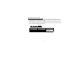
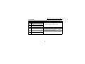
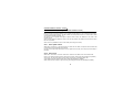
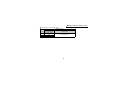
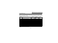
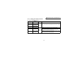
SERAL number check
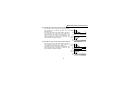
• This product may be used with the FR-A500 series manufactured in and after February 1998. Any of the
models may be used with this unit if its SERAL number indicated on the rating plate and package has the
following version or later.
SERIAL is made up of 1 version symbol, 1 alphabet letter or numeric character indicating month, and 7
numeric characters indicating the year and control number as shown below. (Only the first three digits of the
control number are printed on the package.)
8
2
{{{{{{
U
Symbol Year Month Control number
SERIAL number
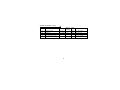
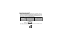
Model
FR-A520-0.4K, 0.75K
FR-A520-1.5K to 11K
FR-A520-15K to 22K
FR-A520-30K to 55K
SERIAL Number
U82{{{{{{
T82{{{{{{
U82{{{{{{
K82{{{{{{
Model
FR-A540-0.4K to 3.7K
FR-A540-5.5K, 7.5K
FR-A540-11K to 22K
FR-A540-30K to 55K
1
SERIAL Number
L82{{{{{{
K82{{{{{{
L82{{{{{{
D82{{{{{{
PRE-OPERATION INSTRUCTIONS
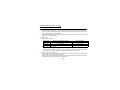
• This product may be used with the FR-V520-1.5K to 7.5K, 30K and 37K manufactured in and after
February 2002. Any of the models may be used with this unit if its SERAL number indicated on the rating
plate and package has the following version or later.
SERAL is made up of 1 version symbol, 1 alphabet letter or numeric character indicating month, and 7
numeric characters indicating the year and control number as shown below. (Only the first three digits
of the control number are printed on the package.)
F
2
2
{{{{{{
Symbol Year Month Control number
SERAL number
Model
FR-V520-1.5K to 7.5K
FR-V520-30K
FR-V520-37K
SERIAL Number
F22{{{{{{
B22{{{{{{
C22{{{{{{
Date Manufactured
in and after
February 2002
2
PRE-OPERATION INSTRUCTIONS
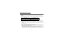
1.2 Packing Confirmation
Make sure that the package includes the following
• Instruction manual ...........................................................................1
• Mounting screws M3 × 10 ...............................................................2
• Terminal resistor jumpers (Jumpers fitted to the terminal block) .....3
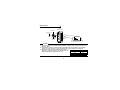
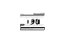
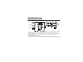
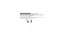
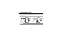
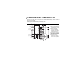
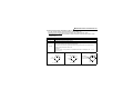
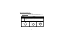
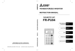
1.3 Structure
Front view
Mounting holes
Rear view
Mounting
hole
Mounting
hole
Terminal
block
screw
size M3
Terminal
symbol
PIN PO 5V SG PA1 PA2 PAR PB1 PB2 PBR PC1 PC2 PCR
FR-A5AP
Terminal resistor jumpers
Option fixing holes
3
Connector
2.INSTALLATION
2.1 Pre-Installation Instructions
(1) Make sure that the input power of the inverter is off.
(2) When the FR-A5AP unit is used for encoder feedback control or orientation control, an encoder (motor
with encoder) and external power supply are required.
When encoder feedback control and orientation control are used together, the encoder (motor with
encoder) and external power supply are shared between these controls.
(3) When the FR-A5AP unit is fitted, the programmed operation function is made invalid.
CAUTION
With input power on, do not install or remove the option unit. Otherwise, the inverter and
option unit may be damaged.
4
INSTALLATION
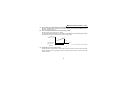
2.2 Installation Procedure
(1) Securely insert the connector of the option unit far into the connector of the inverter. At this time, fit the
option fixing holes snugly. For the position of slot, refer to the next page. Also be sure to fit the unit into
the option fixing hook (For the FR-A500(L) series, it is available in Aug., 2000).
(2) Fit the option unit into the option fixing hook snuggly.
Check that the option board is fixed with the option fixing hook. (as shown on the below)
option board
Check that the option board
is fixed with the option
fixing hook securely.
CAUTION
When the option unit is not securely plugged in the inverter, the inverter may operate improperly
and an unexpected fault may occur.
(3) Securely fix the two right and left places of the option unit to the inverter with the accessory mounting
screws. If the screw holes do not line up, the connector may not have been plugged snugly. Check for
looseness.
5
INSTALLATION
Inverter
(without cover)
Option unit
Accessory screw
(2 pcs.)
Option side
connector
Slot 1
Inverter side connector
Slot 2
Option fixing hook
Slot 3
The slots 1, 2, and 3 are provided
with an option fixing hook.
CAUTION
1. Option fixing hooks are available for the FR-A500(L), F500(L) series inverter produced in and
after Aug., 2000.
2. Only one type of option per inverter may be used. When two or more options are mounted,
priority is in order of slots 1, 2 and 3, the options having lower priority are inoperative.
3. When the inverter cannot recognize that the option is
Mounting Position
Error Display
mounted, it displays the option error. The errors shown
differ according to the mounting slots 1, 2, 3.
Slot 1
E.OP1
Slot 2
Slot 3
6
E.OP2
E.OP3
INSTALLATION
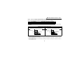
2.3 Wiring
Route the wires so that they do not take up a lot of space in the control circuit terminal block of the option unit.
Wire the twisted pair shielded cable after stripping its sheath to make its cables loose. Also, protect the
shielded cable of the twisted pair shielded cable to ensure that it will not make contact with the conductive
area.
During wiring, do not leave wire off-cuts in the inverter. They may cause a fault, failure or malfunction.
Cable routing
FR-A500 series
FR-V500 series
Shielded cable
Twisted pair shielded cable
REMARKS
The wires with large gaze may not be connected to the terminal block. When connected in parallel, all wires may not
fit in the wiring space due to the increased number of wires. In such cases, perform wiring by using a junction
terminal block.
CAUTION
When installing the inverter front cover, the cables to the inverter's control circuit terminals
and option terminals should be routed properly in the wiring space to prevent them from
being caught between the inverter and its cover.
7
3. ORIENTATION CONTROL—A500(L)
This function is used with a position detector (encoder) installed to the spindle of a machine tool (or the
motor) to allow a rotary shaft to be stopped at the specified position (oriented).
Pr. 350 "stop position command selection" is factory-set to "9999" to make the orientation control function
invalid.
Refer to page 60 for orientation control by the FR-V500 series.
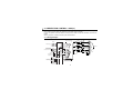
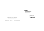
3.1 Wiring Example
Standard motor
with encoder (SF-JR)
(*1)
MCCB
R
Power supply
Inverter
1kΩ
+
-
1000pF
100Ω
1kΩ
U
S
V
T
W
IM
+
-
1000pF100Ω
1000pF
In position
Orientation fault
Output common
External stop
command
FR-A5AP
STF
PA1
STR
PA2
X22 (*5)
PAR
SD
PB1
PB2
ORA
PBR
(*6)
ORM
PC1
PC2
PCR
SE
5V
SG
SD
FR-A5AX
(*7)
X11
X10
C
R
+
-
(*4)
A
N
encoder
(*4)
H
K
(*1)
E
5V 5VDC
0 power supply
(*2)
X1
X0
DY
PB1
PBR
PB2
1000pF100Ω
1000pF
100Ω
100Ω
PC1
PCR
PC2
1000pF100Ω
1kΩ
1kΩ
1µF
B
P
(*4)
100Ω
1kΩ
100Ω
1kΩ
Forward rotation
Reverse rotation
Orientation command
100Ω
PA1
PAR
PA2
(a separate power supply)
8
5V
SG
Jumpers
ORIENTATION CONTROL—A500(L)
*1 When the motor with encoder used is other than the standard motor with encoder (SF-JR), the pin numbers are
different.
To reduce radiated noise, connect the shielded wires of the encoder cables to the case earth (ground) pin.
*2 When orientation control is used with encoder feedback control, the encoder and 5V power supply may be shared
between these controls.
*3 Couple the encoder in line with the motor with a speed ratio of 1 to 1 without any mechanical looseness.
*4 Keep the accessory jumpers connected.
However, when the same encoder is shared between the FR-A5AP and another unit (e.g. NC) which is connected
with a terminal resistor, the built-in terminal resistors are not required and should be removed. (Terminal resistors:
100Ω)
*5 Assign this function to any of the input terminals using Pr. 180 to Pr. 186 (input terminal function selection).
*6 Assign this function to any of the output terminals using Pr. 190 to Pr. 195 (output terminal function selection).
*7 When the stop position command is entered from outside the inverter (externally), the FR-A5AX plug-in option is
required.
9
ORIENTATION CONTROL—A500(L)
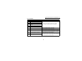
3.2 Terminals
Symbol
Terminal
PA1
Encoder A-phase signal input terminal
Encoder A-phase inverse signal input
PA2
terminal
PB1
Encoder B-phase signal input terminal
Encoder B-phase inverse signal input
PB2
terminal
PC1
Encoder Z-phase signal input terminal
Encoder Z-phase inverse signal input
PC2
terminal
PAR
A-phase terminal resistor terminal
PBR
B-phase terminal resistor terminal
PCR
Z-phase terminal resistor terminal
5V
DC power (positive) input terminal
SG
DC power ground terminal
Description
A-, B- and Z-phase signals are input from the encoder.
For information on the pulse signals, refer to page 14.
Factory-connected with "PA2" by the jumper.
Remove the jumper when the terminal resistor is not needed.
Factory-connected with "PB2" by the jumper.
Remove the jumper when the terminal resistor is not needed.
Factory-connected with "PC2" by the jumper.
Remove the jumper when the terminal resistor is not needed.
Encoder power supply common terminals.
Input encoder power. Connect the positive side to 5V and the
ground side to SG. Also, connect the shield of the shielded wire to
SG.
4.75 to 6VDC (Current consumption 50mA)
10
ORIENTATION CONTROL—A500(L)
<Inverter I/O terminals>
Symbol
X22
(*1)
SD
Terminal
Orientation command input
terminal
Common terminal
Description
Used to enter an orientation signal.
Common terminal for the orientation signal.
Switched low if the orientation has stopped within the in-position
ORA
In-position signal output terminal zone while the start and orientation signals are input.
(*2)
Open collector output. (Permissible load 24VDC, 0.1A)
Switched low if the orientation has not stopped within the
ORM
Orientation fault signal output
in-position zone while the start and orientation signals are input.
(*2)
terminal
Open collector output. (Permissible load 24VDC, 0.1A)
Open collector output common
Common terminal for the ORA and ORM open collector output
SE
terminal
terminals. Isolated from the common terminal of the control circuit.
*1 Assign the function of the X22 signal to any of the input terminals using "input terminal function selection" (Pr.180 to
186).
Refer to the inverter manual for details of input terminal function selection.
*2 Assign the functions of the ORA/ORM signal to any of the output terminals using "output terminal function
selection" (Pr.190 to 195).
Refer to the inverter manual for details of output terminal function selection.
11
ORIENTATION CONTROL—A500(L)
<FR-A5AX, inverter input terminals>
Inverter input
terminals
FR-A5AX
input terminals
Symbol
Terminal
Remarks
Use a micro current
switching contact relay for
the relay contact.
A transistor with the
following specifications
Data read timing should be selected for the
DY*
input signal
open collector signal:
Electrical characteristics of
Common
SD
the transistor used;
terminal (sink)
• IC ≥ 10mA
External
• VCE ≥ 30V
transistor
• Leakage current 100µA
PC common
max.
• If IC ≥ 10mA, VCE(sat)
terminal
voltage is 3V max.
(source)
X0
Digital signal
to
input terminals
X11
Description
Used to input digital signals through either relays or open
collector transistors.
As the command signals are entered, speed or position
commands are selected using Pr. 360.
Used when a digital signal read timing signal is necessary.
Data is only read while terminals DY-SD are shorted. By
opening terminals DY-SD, the data before opening is retained.
Common terminal for digital signal input terminals and data
read timing signals.
When connecting the transistor output (open collector
output) of a programmable controller (PLC), etc., connect
the external power common (positive) to this terminal to
prevent a fault occurring due to leakage current.
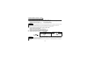
* How to use terminal DY (when the stop position is specified from outside the inverter (externally) ).
When terminals DY-SD are open, the inverter does not import
200ms or longer
DY
data. Therefore, if the input status of the X0-X11 signals change,
the stop position data before opening of terminals DY-SD is valid. Position data
Also, the position data is imported on the leading edge of the DY
Position command latch
signal.
REMARKS
Pr.300 to Pr.305 settings for the FR-A5AX are made invalid when the stop position is set to be specified from outside
the inverter (externally), with the FR-A5AP (orientation control option) fitted to the inverter and when orientation
control is used.
Pr.300 to Pr.305 of the FR-A5AX are made valid when the stop position is not set from outside the inverter.
12
ORIENTATION CONTROL—A500(L)
3.3 Wiring Instructions
(1) Connection with the position detector (encoder).
Use twisted pair shielded cables (0.2mm2 or larger) to connect the FR-A5AP and position detector
(encoder). Cables to terminals 5V and SG should be connected in parallel or be larger in size according
to the cable length as indicated in the table below.
To protect the cables from noise, run them away from any source of noise (e.g. the main circuit and
power supply voltage).
(2) Cable length.
1)Cable length within 30m.
Larger-Size Cable
Within 10m
Number of Parallel Cables of 0.2mm2 Required
At least 2 cables
Within 20m
At least 4 cables
0.75mm2 or larger
Within 30m
At least 6 cables
1.25mm2 or larger
Cable Length
0.4mm2 or larger
2)Cable length of more than 30m.
Use a power supply slightly higher than 5V (approximately 5.5V) in addition to 6 or more parallel
cables of 0.2mm2 or cables of 1.25mm2 or more. This allows the cable length to be increased up to
100m. Note that the voltage applied across terminals 5V-SG must not exceed 6V.
3)Connection with NC. (Or similar device)
When one position detector is shared between the
FR-A5AP and NC (or another device), its output signals should be connected as shown below. In this
case, the cable length between the FR-A5AP and NC
should be as short as possible, within 5m.
Position detector
encoder
Inverter
FR-A5AP
NC
Max. 5m
(2 parallel cables)
13
ORIENTATION CONTROL—A500(L)
(3) Connection of terminal resistors.
Use the jumpers across PA2-PAR, PB2-PBR and PC2-PCR to connect terminal resistors to the A, B
and C-phases of the encoder. Normally, keep the jumpers fitted.
However, remove the jumpers when the same encoder is shared between the FR-A5AP and the other
unit (e.g. NC) which is connected with a terminal resistor.
(4) Position detector (encoder).
Line driver LED type encoder
A. A signal 1000ppr to 4096ppr
B. B signal 1000ppr to 4096ppr
Z. Z signal 1ppr
Output pulse specifications
P
a b c d
A
A
B
B
2.4 to 5.25V
H
1000ppr to 4096ppr
L
0 to 0.4V1000ppr to 4096ppr
1000ppr to 4096ppr
1000ppr to 4096ppr
1ppr
1ppr
Z
Z
a, b, c and d should be (1/4 ± 1/8)P when rotation is clockwise
as viewed from the shaft end of the encoder.
<Example of encoder available on the market>
Use an encoder which has an output circuit equivalent to AM26LS31 or 74LS113.
Pin Numbers of encoder Output Signals
Pin Number
Output Signal
C
A-phase signal
R
A-phase inverse signal
A
B-phase signal
Pin Number
Output Signal
N
B-phase inverse signal
B
Z-phase signal
P
Z-phase inverse signal
Pin Number
Output Signal
H
+5V power supply
K
Power supply common
E
Case earth (ground)
CAUTION
When encoder feedback control and orientation control are used together, the encoder is shared
between these controls.
Use an encoder which has a pulse count of 1000 to 4096ppr (pulses per revolution).
14
ORIENTATION CONTROL—A500(L)
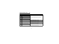
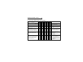
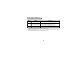
3.4 Parameter List
Parameter
Number
Name
Minimum
Setting
Increments
0, 1, 9999
1
0 to 30Hz
0.01Hz
0 to 10Hz
0.01Hz
0 to 16383(*)
1
Setting Range
Factory
Setting
350
351
352
353
Stop position command selection
Orientation speed
Creep speed
Creep select position
9999
2Hz
0.5Hz
511
354
Position loop select position
0 to 8191
1
96
355
DC injection braking start position
0 to 255
1
5
356
Internal stop position command
0 to 16383(*1)
1
0
357
In-position zone
0 to 255
1
5
358
359
Servo torque selection
Encoder rotation direction
0 to 13
0, 1
1
1
1
1
360
12-bit data selection
0, 1, 2 to 127
1
0
Remarks
9999: No orientation
Set using ± with respect to the
stop position.
Set using ± with respect to the
stop position.
Set using ± with respect to the
stop position.
0: Speed command, 1: Position
command, 2 to 127: Number of
stop positions -1
361
Position shift
0 to 16383(*1)
1
0
362
Position loop gain
1 to 10
1
1
363
In-position signal output delay time
0 to 5 s
0.1 s
0.5 s
364
Encoder stop check time
0 to 5 s
0.1s
0.5 s
*1 When the FR-DU04 is used, up to 9999 may be set. When the FR-PU04 is used, up to maximum may be set.
15
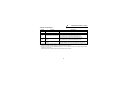
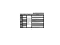
ORIENTATION CONTROL—A500(L)
Parameter
Number
Name
365
Orientation time limit
366
Recheck time
369
Encoder pulse count
376
(*2)
Open cable detection enable/
disable selection
Setting Range
Minimum
Setting
Increments
Factory
Setting
Remarks
0 to 60 s,
9999
0 to 5 s 9999
1s
9999
9999: 120 s setting
0.1 s
9999
0 to 4096
1
1024
9999: No check
Number of pulses before it is
multiplied by 4
0, 1
1
0
0: Function disabled,
1: Function enabled
*2 Parameter available with an upgraded inverter. Refer to the inverter manual for the availability of the parameter.
16
ORIENTATION CONTROL—A500(L)
3.5 Parameter Settings
3.5.1
Setting of stop position command
(1) Pr. 350 "stop position command selection" (factory setting: 9999)
• For the stop position command, either the internal stop position command or the external stop
position command using external signals (12-bit data) may be selected.
• Set "9999" in Pr. 350 to make orientation control invalid.
Pr. 350 Setting
0
1
9999
Description
Internal stop position command
External stop position command
Orientation control invalid (factory setting)
(2) Pr. 369 "number of encoder pulses" (factory setting: 1024)
Set the number of encoder pulses.
Set the number of pulses before it is multiplied by 4.
Example:
Set "1024" for 1024 pulses per revolution (ppr).
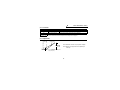
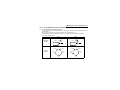
(3) Pr. 359 "encoder rotation direction" (factory setting: 1)
Indicates the direction in which the encoder rotates.
Pr. 359=0
CW
Pr. 359=1 (factory setting)
CCW
A
encoder
Forward rotation is clockwise
rotation when viewed from A.
17
Forward rotation is counterclockwise
rotation when viewed from A.
ORIENTATION CONTROL—A500(L)
(4) Pr. 361 "position shift" (factory setting: 0)
The stop positions are those defined by the position command plus the value set in Pr. 361.
<Position shift function>
Shifts the origin according to the compensation value without changing the origin of the position
detector (encoder).
REMARKS
When the FR-A5AP is fitted and Pr. 350 "stop position command selection" is set to make orientation control valid, the
PU (FR-DU04/FR-PU04) shows the rotation direction of the encoder.
Make setting so that FWD is displayed when the STF signal turns on or REV is displayed when the STR signal turns on.
3.5.2
Internal stop position command
(1) Pr. 356 "internal stop position command" (factory setting: 0)
Setting "0" in Pr. 350 "stop position command selection" chooses the internal position command mode.
In the internal position command mode, the value set in Pr. 356 is the stop position. When the encoder
pulse count is 1024prr, one revolution of the encoder (360 degrees) is divided into 4096 positions, i.e.
360 degrees/4096 pulses = 0.0879 degrees/pulses per address, as shown below. The stop positions
(addresses) are indicated in parentheses.
Origin (0)
Origin (0)
CW
CCW
90°
(1024)
270°
(3072)
270°
(3072)
90°
(1024)
180°(2048)
Pr. 359=0
180°(2048)
Pr. 359=1
18
ORIENTATION CONTROL—A500(L)
3.5.3
External stop position command
(1) Pr. 360 "12-bit data selection" (factory setting: 0)
When "1" is set in Pr. 350 "stop position command selection" and the FR-A5AX option is used with the
FR-A5AP, set stop positions using 12-bit data. The stop position command is a binary input regardless
of the Pr. 304 setting.
•The value set in Pr. 360 "12-bit data selection" should be the number of stop positions less 1.
<Example>
When the number of stop positions is 20 (divided at intervals of 18°), 20 - 1 = 19. Hence, set "19".
• The stop position command is entered in binary when using the FR-A5AX.
Pr. 360 Setting
0
1
2 to 127
Description
Speed command
Position command (*1)
The external stop position command may be used to set up to 128 stop positions at regular
intervals. If the external stop command entered is greater than the setting, the stop
positions are the same as those in the maximum external stop command value.
*1 When the value set in Pr. 369 "encoder pulse count" is 1024 or more, the 12-bit command is not a position
command but the number of positions divided into 4096.
19
ORIENTATION CONTROL—A500(L)
[Example 1]
4 stop positions
Origin (0)
270°
(3 or more)
[Example 2]
8 stop positions
(7 or more) Origin (0)
45°(1)
315°
CW
90°
(1)
180°
(2)
Pr. 360 = "3"
[Example 3]
120 stop positions
(6)270°
Origin (0)
90°(2)
270°
(90)
CW
At intervals 90°
of 3°
(30)
135°(3)
(5)225°
180°
(60)
180°(4)
Pr. 360 = "119"
Pr. 360 = "7"
REMARKS
Values in parentheses indicate binary data entered from the input terminals of the FR-A5AX. If the position signal
monitoring (Pr. 52 "DU/PU main display screen data selection" = 19) is selected, the data monitored is not the number
of stop positions but is 0 to 4095 pulses.
• Relationships between stop position command and 12-bit data Pr. 350
Pr.350
"stop position
command selection"
0: Internal
1: External
Pr.360
"12-bit data selection"
0: Speed command
1, 2 to 127: Position command
0: Speed command
1: External
1, 2 to 127: Position command
Stop position
command
Internal(Pr.356)
Internal(Pr.356)
External(Pr.356)
External (Internal
when FR-A5AX is
not fitted(Pr.356))
20
Operating Status
12-bit data
Speed command
(FR-A5AX)
Speed command
12-bit data
Invalid
External command (or PU)
Speed command
12-bit data
Position command
External command (or
PU)
ORIENTATION CONTROL—A500(L)
3.5.4
Time setting
(1) Pr. 363 "in-position signal output delay time" (factory setting: 0.5 s)
When the motor shaft enters the in-position zone, the in-position signal is output after a delay of the
time set in Pr. 363. Also, when the motor shaft comes out of the in-position zone, the in-position signal
is switched off after a delay of the time set in Pr. 363.
(2) Pr. 364 "encoder stop check time" (factory setting: 0.5 s)
When the in-position signal has not yet been output in orientation operation, the orientation fault signal
is output if orientation cannot be completed and the encoder is stopped for the period of time set in Pr.
364. When the in-position signal has been output once, the orientation fault signal is output if the
orientation cannot be completed again within the time set in Pr. 364.
(3) Pr. 365 "orientation time limit" (factory setting: 9999)
If orientation cannot be completed within the time set in Pr. 365, which is measured from when the
current position signal has passed the creep select position, the orientation fault signal is output.
(4) Pr. 366 "recheck time" (factory setting: 9999)
If the start signal is switched off with the orientation command ON after the encoder is stopped under
orientation control, the current position is checked again after the time set in Pr. 366 has elapsed and
the in-position signal or orientation fault signal is output according to the check result.
21
ORIENTATION CONTROL—A500(L)
3.5.5
Servo torque selection
(1) Pr. 358 "servo torque selection" (factory setting: 1)
Function
Pr. 358 Setting
Remarks
0 1 2 3 4 5 6 7 8 9 10 11 12 13
1) Selection of servo torque function
until output of in-position signal.
× { { { { × { × { × { × × {
{ : Servo torque function valid
× : Servo torque function invalid
2) Retry function selection.
× × × × × × × { × × × { × × × : Retry function invalid
3) Output frequency is compensated
for when motor shaft stops outside
in-position zone.
× × { { × { { × × × × × { { × : Frequency compensation
{ : Retry function valid
{ : Frequency compensation valid
invalid
4) DC injection brake or servo torque is
selected when the motor shaft
{ ×
comes out of the in-position zone
after the in-position signal is output.
× × × { { { { { { { { {
{ : DC injection brake selected
× : Servo torque selected
5) Selection of DC injection brake or
orientation termination timing.
{ : Start signal (STF, STR) or
orientation command is
switched off
{ { { × × { { { { × × × × ×
× : Orientation command is
switched off
6) Selection of in-position signal OFF;
when motor shaft comes out of inposition zone after in-position
signal is output once.
{ : In-position signal is switched
off when motor shaft comes
out of in-position zone.
× : In-position signal remains on if
{ { { { { × × × × × × × × ×
motor shaft comes out of inposition zone.
(Orientation fault signal is not
output.)
22
ORIENTATION CONTROL—A500(L)
REMARKS
• If the orientation command is switched off with the start signal remaining on, the motor accelerates toward the
command speed.
• If the motor shaft shifts to outside the stop position setting range, the servo torque function returns the motor shaft
to the stop position (when sufficient torque can be developed). When orientation control is selected, servo torque is
available for vector control, V/F control and all other controls.
1) Selection of servo torque function until the in-position signal is output
Set Pr. 358 "servo torque selection" to determine whether servo torque is required or not. When
the current position signal is between the orientation stop position and DC injection brake start
position, servo torque is not generated. The shaft is held by DC injection brake. If the current
position signal comes out of this zone due to external force, etc., servo torque is generated to
return the current position signal to within the zone.
Once the in-position signal is output, operation is performed in accordance with the setting in 4).
2) Retry function
Set Pr. 358 "servo torque selection" to determine whether the retry function is required or not.
Note that this function cannot be used with the servo torque function. If the motor shaft is
confirmed to have stopped but is not in the in-position zone, the retry function causes the shaft to
be oriented again.
This retry is made three times, including the first orientation, but no more than three times. (The
orientation fault signal is not output during retry operation.)
3) Frequency compensation function for use when the motor shaft has stopped outside the
in-position zone
When the motor shaft has been stopped by external force, etc. before entering the in-position
zone, the output frequency is increased to move the shaft to the orientation stop position. This
output frequency rises gradually to the creep speed set in Pr. 352. This function cannot be used
with the retry function.
23
ORIENTATION CONTROL—A500(L)
4) Selection of whether DC injection brake or servo torque is started when the motor shaft
comes out of the in-position zone after the in-position signal has been output once.
You can select whether to start DC injection brake to lock the shaft or to start servo torque to
return the shaft to the orientation stop position if the motor shaft comes out of the in-position zone
due to external force, etc. after the output of the in-position signal.
5) Selection of DC injection brake, servo torque or orientation termination timing
To terminate orientation, switch off the start signal (STF or STR) and then switch off the
orientation command (X22). At this time, you can select the point of switching off the in-position
signal between when the start signal is switched off or when the orientation command is switched
off.
6) In-position signal OFF selection; for use when the motor shaft comes out of the in-position
zone after the in-position signal is output once
You can select either the mode in which the in-position signal is switched off when the motor shaft
comes out of the in-position zone or the mode in which the in-position signal remains on
(orientation fault signal is not output) when the motor shaft comes out of the in-position zone.
(2) Pr. 362 "position loop gain" (factory setting: 1)
When Pr. 358 "servo torque selection" value has been set to choose the servo torque function, the
output frequency provided to generate servo torque rises gradually up to the creep speed set in Pr. 352
according to the inclination set in Pr. 362 "position loop gain". Increasing the setting will increase the
operation speed but may cause the machine to hunt.
24
ORIENTATION CONTROL—A500(L)
3.5.6
Changing the monitor display
Monitoring
Description
Set "19" in Pr. 52 to display the position signal on the PU instead of the output voltage.
Position signal monitoring
(Displayed only when the FR-A5AP is fitted.)
Set "22" in Pr. 52 to display the orientation status on the PU instead of the output voltage.
(Displayed only when the FR-A5AP is fitted.)
0 - Orientation not selected (i.e. orientation mode has not been activated) or orientation
speed has not been reached.
1 - Orientation speed reached.
2 - Creep speed reached.
Orientation status
3 - Position loop reached.
4 - In-position.
5 - Orientation fault (pulse stop).
6 - Orientation fault (orientation time limit elapsed).
7 - Orientation fault (recheck).
8 - Positioning orientation in progress.
3.5.7
Break in the cable detection enable/disable selection
This parameter is available with an upgraded inverter. Refer to the inverter manual for the availability of the
parameter.
(1) Pr. 376 "break in the cable detection enable/disable selection" (factory setting: 0)
When the encoder signal turns off, it is judged as an inverter alarm (E.OSD) and the output is shut off.
Pr. 376 Setting
0
1
Description
Open cable detection disable
Open cable detection enable
25
ORIENTATION CONTROL—A500(L)
3.6 Operation
3.6.1
Orientation starting during rotation
1) The orientation command (X22) causes the motor to decelerate to the orientation speed set in Pr.
351 "orientation speed". (Pr. 351 factory setting: 2Hz)
2) After the orientation speed is reached, the motor decelerates to the creep speed set in Pr. 352 "creep
speed" as soon as the current position signal reaches the creep select position set in Pr. 353 "creep
select position". (Pr. 352 factory setting: 0.5Hz, Pr. 353 factory setting: 511)
3) Furthermore, the position loop begins to work as soon as the current position signal reaches the
position loop select position set in Pr. 354 "position loop select position". (Pr. 354 factory setting: 96)
4) After the position loop is selected, the motor keeps decelerating until the current position signal
reaches the DC injection brake start position set in Pr. 355 "DC injection brake start position", at
which time DC injection brake is started to stop the motor. (Pr. 355 factory setting: 5)
5) When the motor has stopped within the in-position zone set in Pr. 357 "in-position zone", the inposition signal (ORA) is output with a delay of the in-position signal output delay time set in Pr. 363
"in-position signal output delay time". If the current position signal comes out of the in-position zone
due to external force etc., the in-position signal is switched off with a delay of the in-position signal
output delay time set in Pr. 363 "in-position signal output delay time". (Pr. 357 factory setting: 5)
6) The orientation fault signal (ORM) is output if the orientation cannot be completed within the time set
in Pr. 365 "orientation time limit" after the current position signal has passed the creep select
position.
7) If the orientation (once started) has been stopped by an external force etc. before the in-position
zone is reached and the in-position signal (ORA) is not yet output, the orientation fault signal (ORM)
is output after the encoder stop check time set in Pr. 364 "encoder stop check time" has elapsed. If
the current position signal comes out of the in-position zone due to an external force etc. after the
output of the in-position signal (ORA), the in-position signal (ORA) is switched off after a delay of the
in-position signal output delay time set in Pr. 363 "in-position signal output delay time". If the
orientation cannot be completed within the encoder stop check time set in Pr. 364 "encoder stop
check time", the orientation fault signal (ORM) is output.
26
ORIENTATION CONTROL—A500(L)
8) When the start signal (STF or STR) is switched off with the orientation command on after the inposition signal (ORA) or orientation fault signal (ORM) has been output once, the in-position signal
(ORA) or orientation fault signal (ORM) is output again after the recheck time set in Pr. 366 "recheck
time" has elapsed.
9) The in-position signal (ORA) and orientation fault signal (ORM) are not output if the orientation
command is off.
REMARKS
If the orientation command is switched off with the start
signal on, the motor accelerates to the command speed.
Orientation
speed
Position loop
Origin
Orientation
DC injection brake start position
Position
loop selection
Creep selection Creep speed
Operations timing chart
Spindle speed
(encoder)
Orientation speed (set in Pr. 351)
Creep speed (set in Pr. 352)
0
Start signal (across STF/STR-SD)
Orientation command
(across X22-SD)
ON
OFF
ON
Current position signal
DC injection
brake start position
(set in Pr. 355)
Origin signal
OFF
DC injection brake
OFF
In-position signal
(across ORA-SE)
27
OFF
OFF
Creep select position
(set in Pr. 353)
Position loop select position
(set in Pr. 354)
Stop position command
ON
OFF
ON
OFF
ORIENTATION CONTROL—A500(L)
3.6.2
Orientation starting during stop
Switch on the orientation command (X22), then switch on the start signal to start and accelerate the motor
to the orientation speed set in Pr. 351 "orientation speed" and perform orientation using the same
procedure as in "orientation starting during rotation". Note that if the current position signal is within the DC
injection brake start position, the spindle speed will not rise to the orientation speed and the DC injection
brake is applied.
Operation timing chart
Orientation speed
Creep speed
Spindle speed
(encoder)
Start signal
(across STF/STR-SD)
Orientation command
(across X22-SD)
DC injection brake
In-position signal
(across ORA-SE)
OFF
ON
OFF
OFF
ON
OFF
OFF
ON
OFF
OFF
ON
OFF
28
ORIENTATION CONTROL—A500(L)
3.6.3
Multi-position orientation
Orientation starting with orientation command and STF/STR kept on
(Orientation starting in the orientation completion state)
Orientation speed
Creep speed
Spindle speed
(encoder)
Start signal
ON
Orientation command
In-position signal
ON
ON
OFF
ON
OFF
DY
200ms or longer
Position signal
Position command latch
Position command latch
• Position data is read on the leading edge of DY (refer to the FR-A5AX instruction manual).
• If the current position signal is within the creep select position, the spindle speed rises not to the
orientation speed but to the creep speed.
• If the current position signal is outside the creep select position, the spindle speed rises to the
orientation speed.
• If the current position signal is within the DC injection brake start position, the DC injection brake is
applied.
29
ORIENTATION CONTROL—A500(L)
3.7
Instructions
(1) The encoder should be coupled with the motor shaft or the spindle oriented with a speed ratio of 1 to 1
without any mechanical looseness.
(2) The DC injection brake operated for positioning must be released in the shortest time (within several
seconds). Operating the brake continuously can cause the motor to generate heat and burn out.
(3) The servo lock function is not available after positioning stop. If the spindle must be held securely,
prepare an appropriate holding means such as a mechanical brake or a dowel pin.
(4) To ensure correct positioning, the encoder must be set in the proper rotation direction and the A and B
phases connected correctly.
(5) The orientation fault signal may be output if the pulse signal is not given from the encoder during
orientation due to a signal loss or the like.
(6) When orientation control is exercised, orientation cannot be completed if "no DC injection brake
operation" is set in the DC injection brake adjusting (voltage, frequency, speed, time) parameters.
These parameters must be set to operate the DC injection brake.
(7) To terminate orientation, the start signal (STF or STR) must be first switched off and the orientation
signal (X22) must be switched off. As soon as this orientation signal is switched off, orientation control
ends. Depending on the Pr.358 "servo torque selection" settings, the orientation state remains if the
orientation signal is on even after the DC injection brake is released at the switching off of the start
signal. Therefore, the orientation status of the monitor function does not return to 0.)
(8) When the retry function of in Pr. 358 "servo torque selection" is selected, the retry operation is
performed three times including the first orientation.
(Note: The first orientation counts as 1 retry.)
30
ORIENTATION CONTROL—A500(L)
(9) For orientation control, set correct values in Pr. 350 "stop position command selection" and Pr. 360 "12bit data selection" (external position command selection).
If the values set are incorrect, proper orientation control will not be performed.
(10) If "8888" (DC dynamic injection external selection) is set in Pr. 11 "DC injection brake operation time",
the DC injection brake is not operated unless the X13 terminal signal is switched on. For orientation
control, the DC injection brake is operated independently of the X13 signal.
(11) When orientation control is exercised, PID control is invalid.
31
ORIENTATION CONTROL—A500(L)
3.8 Specifications
±1.5 degrees
Stop position accuracy Depends on the load torque, load inertia moment, orientation speed, creep speed, position loop
select position, etc.
Encoder-mounted shaft speed (6000r/min)
Permissible rotation
The motor and encoder-mounted shaft must be coupled directly or via a belt without any slip. A
speed
gear change type cannot be used.
• Orientation and creep speed setting.
• Stop position command selection.
• DC injection brake start position setting.
• Creep speed and position loop select position setting.
Functions
• Position shift.
• In-position zone.
• Position signal monitoring, etc.
Note: Set the above functions from the parameter unit.
Holding force after
Without servo lock function (However, the servo lock function is valid when "2" is set in Pr. 370
to choose vector control.)
positioning
• Orientation command.
Input signals
• Forward and reverse rotation commands.
• Stop position command (open collector signal may also be entered). Maximum 12-bit binary
(contact input)
signal.
Output signals (open • In-position signal.
• Orientation fault signal.
collector output)
Prepare a 5VDC power supply for the encoder.
(Usually approximately 350mA)
5V, 50mA is also required for the option.
Supply power from the NC or use a general power supply.
DC power supply
Example:DENSEI-LAMBDA EWS15-5 (5V, 3A)
*When encoder feedback control and orientation control are used together, the 5V power
supply is shared between these controls.
32
4. ENCODER FEEDBACK CONTROL—A500(L)
The FR-A500(L) series fitted with the FR-A5AP can exercise encoder feedback control.
For the FR-V500 series, vector control can be exercised without the FR-A5AP and encoder feedback
control is not exercised with the FR-A5AP.
This function is used with a speed detector (encoder) to allow the motor speed to be detected by the speed
detector and fed back to the inverter so that the output frequency of the inverter is controlled to keep the
motor speed constant to load variations.
Pr. 367 "speed feedback range" is factory-set to "9999" and Pr. 370 "control mode selection" to "0", making
this function invalid.
33
ENCODER FEEDBACK CONTROL—A500(L)
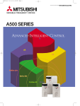
4.1 Wiring Example
MCCB
Power supply
Standard motor
with encoder (SF-JR)(*3)
Inverter
U
R (L1)
V
S (L2)
W
T (L3)
IM
Frequency setting
potentiometer
STF
STR
SD
10
2
5
PA1
PA2
PAR
PB1
PB2
PBR
5V
SG
1000pF
100Ω
1kΩ
100Ω
1000pF 100Ω
FR-A5AP
Forward rotation
Reverse rotation
1kΩ
+
-
+
-
C
R
(*4)
(*4)
A
N
1000pF
1kΩ
100Ω
100Ω
1000pF 100Ω
encoder
1kΩ
1µF
H
K
E
PA1
PAR
PA2
PB1
PBR
PB2
Jumpers
5V
SG
(*1)
5V 5VDC
0 power supply
(*2)
*1 When the motor with encoder used is other than the standard motor with encoder (SF-JR), the pin numbers are
different.
To reduce radiation noise, connect the shielded wires of the encoder cables to the cable earth (ground) pin.
*2 When encoder feedback control is used with orientation control, the encoder and 5V power supply may be shared
between these controls.
*3 Couple the encoder in line with the motor with a speed ratio of 1 to 1 without any mechanical looseness.
*4 Keep the accessory jumpers connected.
However, when the same encoder is shared between the FR-A5AP and the other unit (e.g. NC) which is connected
with a terminal resistor, the built-in terminal resistors are not required and should be removed. (Terminal resistors;
100Ω)
34
ENCODER FEEDBACK CONTROL—A500(L)
4.2 Terminals
Symbol
Symbol Terminal
PA1
Encoder A-phase signal input terminal
Encoder A-phase inverse signal input
PA2
terminal
PB1
Encoder B-phase signal input terminal
Encoder B-phase inverse signal input
PB2
terminal
PAR
A-phase terminal resistor terminal
PBR
B-phase terminal resistor terminal
5V
DC power (positive) input terminal
SG
DC power ground terminal
Description
A and B-phase signals are input from the encoder.
For information on the pulse signals, refer to page 37.
Factory-connected with "PA2" by the jumper.
Remove the jumper when the terminal resistor is not needed.
Factory-connected with "PB2" by the jumper.
Remove the jumper when the terminal resistor is not needed.
Encoder power supply common terminals.
Input encoder power. Connect the positive side to 5V and the
ground side to SG. Also, connect the shield of the shielded wire to
SG.
4.75 to 6VDC (Current consumption 50mA)
35
ENCODER FEEDBACK CONTROL—A500(L)
4.3 Wiring Instructions
(1) Connection with the speed detector (encoder)
Use twisted pair shielded cables (0.2mm2 or larger) to connect the FR-A5AP and speed detector
(encoder). Cables to terminals 5V and SG should be connected in parallel or be larger in size according
to the cable length table as indicated below.
To protect the cables from noise, run them (at least 10cm) away from any source of noise (e.g. the main
circuit and power supply voltage).
(2) Cable length
1)Cable length within 30m
Cable Length
Number of Parallel Cables of 0.2mm2
Larger-Size Cable
Within 10m
At least 2 cables
0.4mm2 or larger
Within 20m
At least 4 cables
0.75mm2 or larger
Within 30m
At least 6 cables
1.25mm2 or larger
2)Cable length of more than 30m
Use a power supply slightly higher than 5V (approximately 5.5V) in addition to 6 or more parallel
cables of 0.2mm2 or cables of 1.25mm2 or more. This allows the cable length to be increased up to
100m. Note that the voltage applied across terminals 5V-SG must not exceed 6V.
(3) Connection of terminal resistors
Use the jumpers across PA2-PAR and PB2-PBR to connect terminal resistors to the A and B-phases
of the encoder. Normally, keep the jumpers fitted.
However, remove the jumpers when the same encoder is shared between the FR-A5AP and the other
unit (e.g. NC) which is connected with a terminal resistor.
36
ENCODER FEEDBACK CONTROL—A500(L)
(4) Speed detector (encoder)
Line driver LED type encoder
Output pulse specifications
a
A. A signal 1000ppr to 4096ppr
b
P
c
d
A
A
B. B signal 1000ppr to 4096ppr
2.4 to 5.25V (High)
0 to 0.4V (Low)
B
B
a, b, c and d should be (1/4 ± 1/8)P when rotation is clockwise
as viewed from the shaft end of the encoder.
<Example of encoder available
on the market>
<AM26L31, 74LS113
equivalent>
Pin Numbers of Encoder Output Signals
Pin Number
Output Signal
Pin Number
Output Signal
C
A-phase signal
H
+5V power supply
R
A-phase inverse signal
K
Power supply common
A
B-phase signal
E
Case earth (ground)
N
B-phase inverse signal
REMARKS
When encoder feedback control and orientation control are used together, the encoder is shared between these
controls.
Use the encoder with a pulse count of 1000 to 4096ppr.
37
ENCODER FEEDBACK CONTROL—A500(L)
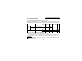
4.4 Encoder Feedback Control and Vector Control Parameter List
Fitting this option unit adds the following parameters. Make setting as necessary.
Parameter
Number
Name
Setting
Range
Minimum
Factory
Setting
Setting
Increments
Control Mode
Encoder
Vector
feedback
control
control
—
{
(*3)
{
{
(*4)
(*4)
22
Torque restriction level
(Stall prevention operation level) (*1)
0 to 300%,
9999
0.1%
150%
29
Acceleration/deceleration pattern
0, 1, 2, 3, 4
1
0
144
Number of motor poles
(Speed setting switchover) (*1)
0, 2, 4, 6, 8,
10, 102, 104,
106, 108, 110
1
4
{
{
0, 1, 2
1
0
{
{
0.01Hz
9999
1
1
{
(*5)
{
{
(*5)
{
0.01Hz
9999
{
—
0.1
1
1
1
0.1%
1
1024
0
1
100%
{
{
{
—
—
—
{
{
{
{
359
Automatic restart after instantaneous
power failure selection
Overspeed detection frequency/excessive
speed deviation detection frequency (*5)
Encoder rotation direction
367
Speed feedback range
368
369
370
371
372
Feedback gain
Number of encoder pulses
Control mode selection
Torque characteristic selection
Speed control P gain
162
285
0 to 30Hz,
9999
0, 1
0 to 400Hz,
9999
0 to 100
0 to 4096
0, 1, 2
0, 1
0 to 200%
38
ENCODER FEEDBACK CONTROL—A500(L)
Parameter
Number
373
374
375
376
380
381
382
383
*1
*2
*3
*4
*5
Name
Speed control I gain
Overspeed detection level
Servo lock gain
Open cable detection enable/
disable selection
Acceleration S pattern 1
Deceleration S pattern 1
Acceleration S pattern 2
Deceleration S pattern 2
Setting
Range
Minimum
Factory
Setting
Setting
Increments
Control Mode
Encoder
Vector
feedback
control
control
—
{
{
{
—
{
0 to 200%
0 to 400Hz
0 to 150
0.1%
0.01Hz
1
20%
120Hz
20
0, 1
1
0
{
{
0 to 50%
0 to 50%
0 to 50%
0 to 50%
1%
1%
1%
1%
0%
0%
0%
0%
—
—
—
—
{
{
{
{
When the FR-A5AP is not fitted, the function names in parentheses are used.
{ in the Control Mode field indicates that the corresponding function is valid.
Functions as the stall prevention operation level.
The acceleration/deceleration pattern C setting (Pr. 29 = 4) is made valid when the FR-A5AP is fitted.
Functions as an overspeed detection frequency under encoder feedback control and as an excessive speed
deviation detection frequency under vector control. Excessive speed deviation detection frequency is a parameter
available with an upgraded inverter. The parameter acts only as an overspeed detection frequency for a standard
inverter. Refer to the inverter manual for the availability of the excessive speed deviation detection frequency.
39
ENCODER FEEDBACK CONTROL—A500(L)
4.5 Pre-Operation Settings
(1) Pr. 144 "number of motor poles (encoder)" (factory setting: 4)
The either of the following motors may be used. Set the number of motor poles according to the motor used:
• Standard motor (with encoder)
: SF-JR 0.2kW to 55kW
• Constant-torque motor (with encoder)
: SF-JRCA 0.4kW to 55kW
REMARKS
1. For vector control, this parameter value is made invalid and the setting of Pr. 81 "number of motor poles" is made
valid.
2. If you set this parameter value to "0, 10 or 110" and operate the inverter, any of E.OP1 to E.OP3 occurs.
3. If you set "102, 104, 106 or 108", that value minus 100 is set as the number of poles.
(2) Pr. 369 "number of encoder pulses" (factory setting: 1024)
Set the number of encoder pulses.
Set the number of pulses before it is multiplied by 4.
Example: Set "1024" for 1024 pulses per revolution (ppr).
(3) Pr. 359 "encoder rotation direction" (factory setting: 1)
(4) Indicates the direction in which the encoder rotates.
Pr. 359=0
CW
Pr. 359=1 (factory setting)
CCW
A
encoder
Forward rotation is clockwise rotation
when viewed from A.
Forward rotation is counterclockwise
rotation when viewed from A.
REMARKS
When the FR-A5AP is fitted and encoder feedback control or vector control is selected, the PU (FR-DU04/FR-PU04)
shows the rotation direction of the encoder.
Make the setting so that FWD is displayed when the STF signal switches on or REV displayed when the STR signal
switches on.
40
ENCODER FEEDBACK CONTROL—A500(L)
4.6 Control Mode Setting
By setting the Pr. 370 "control mode selection" value, you can choose any of encoder feedback control (V/
F control, advanced magnetic flux vector control) and vector control.
Torque control and position control are not performed. (However, torque limit can be done in the vector
control mode.)
When holding torque is required during a stop, choose vector control (zero speed control or servo lock).
Control Mode
V/F control
Encoder
feedback Advanced
control
magnetic flux
vector control
Vector
control (*1)
Motor
Pr. 80,
Pr. 81
Setting
Standard motor with
encoder (same capacity)
9999
Standard motor with
Other than
encoder (same capacity)
9999
Other than
9999
Standard motor with
encoder (same capacity) Other than
9999
Pr. 370
Setting
Pr. 367
Setting
0 (1,2)
Other than
9999
(*2)
Zero
Servo Torque
Speed
Lock
Limit
Control
×
×
×
—
{
×
{
—
×
{
{
0
Other than
9999
1
2
(Pr. 370 factory setting: 0, Pr. 367 factory setting: 9999)
*1 When a speed control range of 1:1000 is required, choose vector control.
If vector control has been chosen, torque control and position control are not performed. The frequency response of
vector control is 10 to 20rad/s.
*2 When Pr. 80 and Pr. 81 = "9999", encoder feedback control (V/F control) is valid if "1" or "2" is set in Pr. 370.
REMARKS
The X18 (RT) signal may be used to select between encoder feedback control + V/F control, encoder feedback
control + advanced magnetic flux vector control and vector control during a stop only. Refer to the inverter manual for
details of the X18 (RT) signal.
41
ENCODER FEEDBACK CONTROL—A500(L)
4.7 Encoder Feedback Control
Make sure that Pr. 80 "motor capacity", Pr. 81 "number of motor poles", Pr. 144 "speed setting change",
Pr. 359 "encoder rotation direction", Pr. 369 "number of encoder pulses" and Pr. 370 "control mode" values
are set properly. (Refer to page 40, 41.)
(1) Pr. 367 "speed feedback range" (factory setting: 9999)
This parameter is used to make the encoder feedback function valid.
Set the speed feedback control range.
(When Pr. 367 = 9999 (factory setting), the encoder feedback function is invalid.)
<Setting>
Define the upper and lower limits in reference to the set value (frequency at which the motor is to be
rotated at constant speed). Normally, set the frequency converted from the rated motor speed (rated
load) and slip (r/min). Too large setting will result in slow response.
Example: Rated speed of a 4-pole motor is 1740r/min (60Hz)
Slip Nsp = synchronous speed - rated speed
= 1800 - 1740 = 60 (r/min)
Frequency equivalent to slip (fsp)
fsp =
Nsp × number of poles
120
Speed feedback range
=
Driven load
60 × 4
120
= 2(Hz)
Regenerative load
Set value
(Set command)
(2) Pr. 368 "feedback gain" (factory setting: 1)
This parameter is valid when encoder feedback control is valid. Set if rotation is instable or response is slow.
When the setting is greater than 1, response is faster but overcurrent or rotational instability is more
liable to occur. When the setting is less than 1, response is slower but rotation is more stable.
42
ENCODER FEEDBACK CONTROL—A500(L)
(3) Instructions for encoder feedback control
1) The number of motor poles used must be checked before starting operation. The number of poles
set must be correct to ensure proper control of the motor.
2) The encoder should be coupled in line with the motor shaft without any mechanical looseness with
a speed ratio of 1 to 1.
3) Make sure that the encoder has been set to the correct rotation direction on the rotation direction
display of the parameter unit. If the rotation direction is not correct, encoder feedback control cannot
be carried out (the inverter can be operated).
4) During acceleration or deceleration, encoder feedback control is not performed to prevent instability
such as hunting. Encoder feedback control is started after the output frequency has once reached
the [set speed] ± [speed feedback range].
5) If any of the following conditions occurs during encoder feedback control operation, the inverter is run at the
output frequency of [set speed] ± [speed feedback range] without coming to an alarm stop and does not
follow up the motor speed:
• The pulse signal from the encoder is switched off due to an open cable, etc.
• An accurate pulse signal cannot be detected due to induction noise, etc.
• The motor is forced to accelerate (regenerative operation) or decelerate (e.g. motor lock) by large
external force.
6) When opening the brake of the motor with brake, use the RUN (running) signal. (The brake may not
be opened if the FU (output frequency detection) signal is used.)
7) During encoder feedback control, do not switch off the 5V power of the encoder. If the power is
switched off, normal encoder feedback control cannot be exercised.
8) Programmed operation cannot be performed in the encoder feedback control mode (when the FRA5AP is fitted).
9) Set Pr. 285 "overspeed detection frequency" to prevent misoperation caused if an accurate signal
cannot be detected from the encoder. This shuts off the output and gives an inverter alarm (E.MB
1) when; (detection frequency) - (output frequency) > Pr. 285.
43
ENCODER FEEDBACK CONTROL—A500(L)
4.8 Vector Control (Zero Speed Control and Servo Lock)
Vector control can be performed when a standard motor with encoder is used.
Make sure that Pr. 80 "motor capacity", Pr. 81 "number of motor poles", Pr. 144 "number of motor poles",
Pr. 359 "encoder rotation direction", Pr. 369 "number of encoder pulses" and Pr. 370 "control mode" values
are set properly. (Refer to page 40, 41.)
Set "100%" in Pr. 89 "speed control gain" to perform vector control. For details of Pr. 89, refer to the
inverter manual.
Servo lock will resist and attempts to move it from the stop position, the limitation is the amount of torque
that can be provided.
Servo lock is only available in vector control mode (when using an encoder).
4.8.1
Zero speed control
When the Pr. 370 value is "1" and Pr. 80 and Pr. 81 values are not "9999", zero speed control is made valid
so that torque may be generated at zero speed.
Use Pr. 22 to set the torque limit level in the zero speed control mode. (150% torque (short duration) is
possible.)
4.8.2
Servo lock
When the Pr. 370 value is "2" and Pr. 80 and Pr. 81 values are not "9999", servo lock is made valid.
Use Pr. 22 to set the torque limit level in the servo lock mode. (150% torque (short duration) is possible.)
Also, use Pr. 375 "servo lock gain" to set the servo lock gain. (Pr. 375 factory setting: 20)
A high setting will make response faster but increase the probability of instability.
When inertia moment is large, a high servo lock gain setting will increase the probability of instability.
44
ENCODER FEEDBACK CONTROL—A500(L)
<Zero speed control and servo lock timing charts>
1) Zero speed control or servo lock is made valid when the pre-excitation terminal (LX) is ON without the
start signal (STF, STR) being entered into the inverter (during a stop). Assign the function of the preexcitation terminal (LX) to any of the terminals using Pr. 180 to Pr. 186.
ON
LX
STF(STR)
OFF
DC injection brake
operation frequency
Output frequency
Zero speed control
or servo lock
OFF
2) Zero speed control or servo lock is made valid when the frequency command is 0Hz (not more than the
starting frequency) with the start signal being entered.
OFF
LX
STF(STR)
Output frequency
Zero speed control
or servo lock
OFF
LX
STF(STR)
OFF
Output frequency
Zero speed control
or servo lock
OFF
OFF
OFF
DC injection brake operation time (Pr. 11)
DC injection brake operation time (Pr. 11)
<Start signal turns OFF after the DC injection brake
operation time has elapsed>
<Start signal turns OFF before the DC injection brake
operation time has elapsed.>
If a start is made during zero speed control or servo lock, online auto tuning is not activated.
3) Zero speed control or servo lock is made valid when the frequency command is not more than the DC
injection brake frequency during deceleration of the inverter. The position at the DC injection brake
operation frequency is held.
OFF
OFF
DC injection brake
operation frequency
LX
STF(STR)
Output frequency
Zero speed control
or servo lock
OFF
DC injection brake operation time
45
ENCODER FEEDBACK CONTROL—A500(L)
4.8.3 Pr. 22 "torque restriction level" (factory setting: 150%)
Torque restriction level
Torque limit may be activated only when vector control is selected. The second and third functions are Pr.
48 "second torque limit level" and Pr. 144 "third torque limit level".
When vector control is not selected, the stall prevention functions are activated. Use the same parameter
numbers for setting. (Refer to the Inverter Instruction Manual.)
The Pr. 22 setting may be changed during operation.
When Pr. 22 = "9999", the torque limit level may be set by entering a signal into the No. 1 terminal. At this
time, the auxiliary input override function of the No. 1 terminal is not activated.
The variable torque limit level analog signal can be limited.
Pr. 22=9999
(200%)
(150%)
Pr. 114
Pr. 48
0V
10(5)V
Input voltage (across terminals 1-5)
46
ENCODER FEEDBACK CONTROL—A500(L)
4.8.4
Pr. 371 "torque characteristic selection" (factory setting: 1)
Used to change the torque characteristic according to the machine characteristics.
Pr. 371 Setting
0
1 (factory setting)
Standard Motor with Encoder (e.g. SF-JR)
Cyclic operation mode
Continuous operation mode
z Torque characteristic of the standard motor with encoder (Example: SF-JR standard motor with encoder
(4 poles))
With Reference to 1800r/min (60Hz) Torque
Cyclic operation mode setting
Continuous operation mode setting
When the inverter used has a capacity one rank higher
When the inverter used has the same capacity as
than that of the motor and the rated voltage is input
that of the motor and the rated voltage is input
150
Torque [%]
1.5kW or less
50%ED
100
Short-duration maximum torque
〕〔
1.5kW or less
Continuous
operation torque
(*2)
Torque [%]
〔
2.2kW or more
50%ED (*3)
50
33
0
900
1800
Speed [r/min]
3600 (*1)
150
〕
Short-duration maximum torque
100
82
2.2kW or more
Continuous
operation torque
(*4)
40
33
0 180 600 1500 1800
Speed [r/min]
3600 (*1)
*1 The maximum speed is 1) 0.4kW to 7.5kW: 3600r/min, 2) 11kW to 30kW: 3000r/min, 3) 37kW to 55kW: 1950r/min.
*2 Continuous, repetitive operation of 50%ED can be performed in cycle time of 10 minutes. Note that the maximum
continuous operation time is 5 minutes.
*3 Use the constant-torque motor (SF-JRCA with encoder) when 50%ED with 100% torque is required for 2.2kW or
more at 900r/min or less.
*4 Use the constant-torque motor (SF-JRCA with encoder) when continuous 100% torque is required for 2.2kW or
more at 600r/min or less.
47
ENCODER FEEDBACK CONTROL—A500(L)
CAUTION
1. When using a motor and inverter which are the same in capacity in cycle operation mode, take
caution that the current average value does not exceed the inverter rating. If the current average
value exceeds, use an inverter whose capacity is one rank higher than the motor.
2. To provide 150% torque from 0Hz to the rated speed of the motor the inverter should be one
rank higher than the motor.
3. Since the motor current increases when using an inverter and motor which are the same in
capacity in cycle operation mode, use them with 80 % or less continuous torque.
4. Continuous operation when the inverter capacity is one rank higher than the motor will produce
the same results as when the inverter and motor capacity are the same (as shown above).
5. If unusual noise from a motor (machine), hunting, or over current alarm occurs in continuous
operation mode when satisfying two of the following conditions, change Pr. 37 "Torque
characteristic selection" to cycle operation mode.
[Conditions]
• Running frequency is equal to or higher than the motor rated frequency.
• Power supply voltage is less than 110% of the rated motor voltage.
When electronic thermal relay function or over current alarm functions in cycle operation mode,
consider using an inverter and motor one rank higher in capacity.
4.8.5
Pr. 372 "speed control P gain" (factory setting: 100%)
Used to set the proportional gain of the speed loop.
A high setting will make the speed response faster but if the setting is too high this will cause vibrations and noise.
4.8.6
Pr. 373 "speed control I gain" (factory setting: 20%)
Used to set the integral gain of the speed loop.
A high setting will shorten restoration time at occurrence of speed variation but if the setting is too high this
will cause speed overshooting.
48
ENCODER FEEDBACK CONTROL—A500(L)
4.8.7
Driving/regenerative status signal output (Y32)
When vector control is selected, the driving/regenerative status is output as a signal.
Assign the function of the output signal to any of the output terminals using Pr. 190 to Pr. 195 "output
terminal function selection".
4.8.8
Operation ready 2 signal (RY2)
Output during operation (on completion of pre-excitation operation) under vector control. (switched on also
during DC injection brake, 0 speed control or servo lock)
When opening the brake of a motor with brake, use the RY2 (operation ready 2) signal. (The brake may not
be opened if the FU (output frequency detection) signal is used.)
4.8.9
Instructions for vector control
1) When using vector control, perform offline auto tuning in the motor rotation mode (while the motor is running).
(Refer to the inverter manual.)
2) Before starting operation, always confirm that the correct number of poles of the motor is used. Proper
speed control cannot be performed if the number of motor poles is incorrect.
3) Couple the encoder in line with the motor shaft with a speed ratio of 1 to 1 without any mechanical looseness.
4) Make sure that the encoder has been set to the correct rotation direction on the rotation direction display
of the parameter unit. If the rotation direction is not correct, vector control cannot be carried out.
5) In the vector control mode, vector control is also exercised during acceleration/deceleration.
6) Do not switch off the 5V power of the encoder during vector control. Proper vector control cannot be
performed if that power is switched off.
7) Proper vector control cannot be performed if the pulse signal from the encoder is lost due to an open cable, etc.
8) In the vector control mode, the carrier frequency is as follows:
49
ENCODER FEEDBACK CONTROL—A500(L)
z Carrier frequency of the FR-A500 series
Pr. 72
Setting
0
1
2
3
4
5
6
7
8
9
10
11
12
13
14
15
*1
*2
V/F control,
advanced magnetic
flux vector control
0.7kHz
1kHz
2kHz
3kHz
4kHz
5kHz
6kHz
7kHz
8kHz
9kHz
10kHz
11kHz
12kHz
13kHz
14kHz
14.5kHz
Carrier Frequency
Vector control
One rank larger *2
1 : 1 *1
18.5K or less 22K or more
Approximately
1kHz
Approximately Approximately
1kHz
1kHz
Approximately Approximately
3kHz
3kHz
Approximately
6kHz
Approximately
3kHz
Approximately
8kHz
Approximately
6kHz
This indicates the carrier frequency when the inverter capacity and the motor capacity are the same.
This indicates the carrier frequency when the inverter capacity is one rank larger than the motor capacity.
The capacities in the table indicate the inverter capacity.
CAUTION
In the vector control mode, set the Pr. 72 "PWM frequency selection" value during a stop.
50
ENCODER FEEDBACK CONTROL—A500(L)
z Carrier frequency of the FR-A500L series
Carrier Frequency
Pr. 72
Setting
0
1
2
V/F control,
advanced magnetic
flux vector control
0.7kHz
1kHz
2.5kHz
Vector control
Approximately 1kHz
51
ENCODER FEEDBACK CONTROL—A500(L)
4.9 Additional Functions
(1) Pr. 162 "selection of automatic restart after instantaneous power failure selection" (factory
setting: 0)
By setting "2" in Pr. 162, automatic restart after instantaneous power failure can be made at the
frequency detected from the encoder. In the vector control mode, automatic restart is made with the
encoder detection frequency searched for, independently of the Pr. 162 setting.
Pr. 162 Setting
0 (factory setting)
1
2
Description
With frequency search
Without frequency search
Encoder detection frequency search
(2) Pr. 285 "overspeed detection frequency"/"excessive speed deviation detection frequency"
(factory setting: 9999)
z When "0" is set in Pr. 370, Pr. 285 acts as an overspeed detection frequency. (Overspeed detection
function)
If (detection frequency (speed)) - (output frequency (speed)) > (Pr. 285 setting), E.MB1 occurs and
the output is shut off.
When Pr. 285 = 9999, overspeed detection is not performed.
z When "1" or "2" is set in Pr. 370, Pr. 285 acts as an excessive speed deviation detection frequency.
(Speed deviation excess detection function)
Excessive speed deviation detection frequency is a parameter available with an upgraded inverter.
This parameter acts only as an over speed detection frequency for a standard inverter. Refer to the
inverter manual for the availability of the excessive speed deviation detection frequency.
If ((actual speed) - (speed command value)) > (Pr. 285 setting), E.OSD occurs and the output is shut off.
52
ENCODER FEEDBACK CONTROL—A500(L)
(3) Pr. 376 "break in the cable detection enable/disable selection" (factory setting: 0)
Parameter available with an upgraded inverter. Refer to the inverter manual for the availability of the
parameter. (Refer to page 25)
(4) Pr. 374 "overspeed detection level" (factory setting: 120Hz)
Used to limit the maximum speed. (0 to 400Hz)
Any speed higher than the speed set in Pr. 374 is judged as overspeed and the corresponding signal is output.
If overspeed is detected, the inverter will not come to an alarm stop.
Speed (r/min)
Speed set in Pr. 374
Pr. 374
Overspeed detection
output (Y29) (*1)
Time
OFF
ON
*1 Assign overspeed detection (Y29) to any of Pr. 190 to Pr. 195 "output terminal function
selection".
(5) Forward/reverse running signal output
Whether forward or reverse rotation is being made is output as a signal according to the actual speed.
Assign the function of the output signal to any of the terminals using Pr. 190 to Pr. 195 "output terminal
function selection".
53
ENCODER FEEDBACK CONTROL—A500(L)
(6) S-shaped acceleration/deceleration C
When the FR-A5AP is fitted, S-shaped acceleration/deceleration C can be selected by setting "4" in Pr.
29 "acceleration/deceleration pattern". The S-shaped acceleration/deceleration C function allows the
speeds of S-shaped acceleration/deceleration to be set in the corresponding parameters and the required
parameter to be selected by the S-shaped acceleration/deceleration C switching terminal (X20).
Assign the function of the S-shaped acceleration/deceleration C switching terminal (X20) to any of the
terminals using Pr. 180 to Pr. 186 "input terminal function selection".
Operation
During Acceleration
During Deceleration
Pr. 380 "S-shaped acceleration 1"
(factory setting: 0%)
Pr. 382 "S-shaped acceleration 2"
(factory setting: 0%)
Pr. 381 "S-shaped deceleration 1"
(factory setting: 0%)
Pr. 383 "S-shaped deceleration 2"
(factory setting: 0%)
S-Pattern
Switching Terminal
OFF
ON
Pr. 382
Pr. 382
Pr. 380
Pr. 381
Pr. 381
Pr. 383
Pr. 383
Pr. 380
S-shaped acceleration/ ON
deceleration C
switching terminal X20 OFF
Also, Pr. 380 to Pr. 383 are used to set the ratio of the S-shaped acceleration/deceleration time (Ts) to
the acceleration/deceleration time (T) in %.
S-shaped acceleration
Linear acceleration
Ts
T
54
ENCODER FEEDBACK CONTROL—A500(L)
CAUTION
During acceleration/deceleration, switching cannot be made using the S-shaped acceleration/
deceleration C switching terminal (X20). When X20 is switched either ON or OFF during either
acceleration or deceleration, the effect of the switch (to select a different acceleration or
deceleration shape) does not take effect until either the acceleration or deceleration has stopped
(i.e. a stable speed has been reached).
4.10 Specifications
Speed variation ratio
Speed control range
Functions
DC power supply
Maximum speed
Frequency response
±0.02% of the maximum speed (3600r/min) in vector control mode
(load variation 0 to 100% at 6Hz or more). (*1)
1:1000 in vector control mode.
• Speed feedback range setting.
• Feedback gain setting.
• Encoder rotation direction setting.
A 5VDC power supply is required for the encoder and option unit.
The 5V power supply can be shared between orientation control and encoder feedback
control.
This power supply is optional.
Power supply 5VDC, current capacity 400mA or more.
(Normally approximately 350mA for encoder and 50mA for option unit)
<Power supply example> DENSEI LAMBDA EWS15-5 (5V 3A)
3600r/min (120Hz)
10 to 20rad/s.
*1 Load variation 100% indicates the maximum continuous operation torque value of the motor output characteristic
(refer to the relevent catalog or FR-A500 series technical information) to the running frequency.
55
5. PULSE TRAIN INPUT—A500(L)
A pulse train signal can be used to enter the speed setting of the inverter.
Pr. 384 is factory set to "0" to make this function invalid.
When the speed is input by the pulse train signal, the multi speed setting of the inverter becomes invalid.
Refer to page 56 for pulse train input with the FR-V500 series.
5.1 Wiring Example
MCCB
Power
supply
Input pulses
Inverter
R (L1)
U
S (L2)
V
T (L3)
W
PC
FR-A5AP
PIN
MCCB
Motor
Power
supply
IM
or
S (L2)
V
T (L3)
W
PC
PIN
FR-A5AP
PO
PO
Open collector input
Open
collector
Input pulses input
Inverter
R (L1)
U
SD
SD
CAUTION
This option unit must be wired using the open collector system to operate it properly.
56
Motor
IM
PULSE TRAIN INPUT—A500(L)
5.2 Terminals
Symbol
PIN
PO
Terminal
Pulse input terminal 1
Pulse input terminal 2
Description
Terminal used to enter a pulse train of 0 to 100kpps (*)
Terminal used to enter a pulse train of 0 to 100kpps (*)
REMARKS
*: Whether an input pulse is entered into PIN or PO depends on the wiring. Refer to page 56.
Output frequency
5.3 Adjustment
Factory setting
(60Hz)
Bias
Pr. 385
Note: Maximum number of input pulses: 100kpps
Gain Pr. 386
0
Note: Number of input pulses are multiplied by 2
internally.
Maximum number of pulses
Input pulses (PPS)
57
PULSE TRAIN INPUT—A500(L)
5.4 Pulse Train Input Parameter List
Minimum
Factory Setting
Increments
384 (*1)
Input pulse frequency division ratio
0 to 250
1
0
385
Zero-input pulse frequency
0 to 400Hz
0.01Hz
0
386
Maximum-input pulse frequency
0 to 400Hz
0.01Hz
60
*1 Indicates the frequency division ratio for the input pulses. The frequency resolution to the input pulses varies with
the setting.
Parameter Number
Name
Setting Range
CAUTION
When the Pr. 384 value is "0" (factory setting), Pr. 385 and Pr. 386 do not function even if their
values have been set.
CAUTION
Note that if you set any value other than 0Hz in Pr. 385, merely turning on the start signal will
start the motor at the preset frequency without a pulse train input command.
58
PULSE TRAIN INPUT—A500(L)
5.5 Setting Example
How to calculate the input pulse frequency division ratio
Use the following formula to calculate the input pulse frequency division ratio in Pr. 384:
Maximum number of input pulses (pps) = Pr. 384 × 400
Pr. 386
Detectable frequency >
2 × 16.6ms × Pr. 384 × 400
The detectable frequency changes with the maximum number of input pulses.
5.6 Specifications
Circuit System
Input current
Max. permissible number of pulses
Input pulse specifications
Response delay
Open Collector System
10mA
100kpps
0f to 250f (f: variable frequency)
16.6ms
59
6. ORIENTATION CONTROL AT A MACHINE END—V500
This function is used with a position detector (encoder) installed to the spindle of a machine tool (or the
motor) to allow a rotary shaft to be stopped at the specified position (oriented). Orientation control at a
machine end is exercised.
Pr. 350 "stop position command selection" is factory-set to "9999" to make the orientation control function invalid.
Refer to page 8 for orientation control by the FR-A500(L) series.
6.1 Wiring Example
MCCB
Power supply
FR-V500
R
S
T
Forward rotation
Reverse rotation
Orientation command
STF
STR
X22(*5)
SD
FR-V5AX
DI16 (*2)
DI15
External stop
position command
In-position signal
DI12
DI11
SD
ORA
SE
U
V
W
Vector inverter motor (SF-V5R)
(*1) A
B
FAN
C
U
V
IM
W
G
OH
SD
G1
G2
PA
PAR
PB
PBR
PZ
PZR
PG
SD
FR-A5AP
A
B
C
D
F
G
S
R
N
PA1
PA2
PAR
PB1
PB2
PBR
PC1
PC2
PCR
5V
SG
Thermal
protector
encoder
(*3)
C Machine end encoder
R
A
N
B
P
encoder
H
K
(*4)
5VDC power supply
(a separate power supply)
60
Main circuit terminal
Control circuit terminal
*1 The motor fan power supply is
single-phase when the motor
capacity is 7.5kW or less.
*2 When the stop position
command is entered from
outside the inverter
(externally), the FR-V5AX, FRV5AH or FR-A5AX plug-in
option is required.
*3 For the terminal specifications,
refer to the inverter manual.
*4 For the terminal specifications,
refer to page 66
*5 Assign any of terminals
functions in input terminal
function selection (Pr.180 to
Pr.183 and Pr.187).
ORIENTATION CONTROL AT A MACHINE END—V500
6.2 Terminals
Symbol
Terminal
PA1
Encoder A-phase signal input terminal
Encoder A-phase inverse signal input
PA2
terminal
PB1
Encoder B-phase signal input terminal
Encoder B-phase inverse signal input
PB2
terminal
PC1
Encoder Z-phase signal input terminal
Encoder Z-phase inverse signal input
PC2
terminal
PAR
A-phase terminal resistor terminal
PBR
B-phase terminal resistor terminal
PCR
Z-phase terminal resistor terminal
5V
DC power (positive) input terminal
SG
DC power ground terminal
Description
A-, B- and Z-phase signals are input from the encoder.
For information on the pulse signals, refer to page 66.
Factory-connected with "PA2" by the jumper.
Remove the jumper when the terminal resistor is not needed.
Factory-connected with "PB2" by the jumper.
Remove the jumper when the terminal resistor is not needed.
Factory-connected with "PC2" by the jumper.
Remove the jumper when the terminal resistor is not needed.
Encoder power supply common terminals.
Input encoder power. Connect the positive side to 5V and the
ground side to SG. Also, connect the shield of the shielded wire to
SG.
4.75 to 6VDC (Current consumption 50mA)
61
ORIENTATION CONTROL AT A MACHINE END—V500
<Inverter I/O terminals>
Symbol
X22
(*1)
SD
Terminal
Orientation command input
terminal
Common terminal
Description
Used to enter an orientation signal.
Common terminal for the orientation signal.
Switched low if the orientation has stopped within the in-position
ORA
In-position signal output terminal zone while the start and orientation signals are input.
(*2)
Open collector output. (Permissible load 24VDC, 0.1A)
Open collector output common
Common terminal for the ORA and ORM open collector output
SE
terminal
terminals. Isolated from the common terminal of the control circuit.
*1 Assign the function of the X22 signal to any of the input terminals using "input terminal function selection" (Pr.180 to
Pr. 183, Pr. 187).
Refer to the inverter manual for details of input terminal function selection.
*2 Assign the functions of the ORA signal to any of the output terminals using "output terminal function selection"
(Pr.190 to Pr. 192, Pr. 195).
Refer to the inverter manual for details of output terminal function selection.
62
ORIENTATION CONTROL AT A MACHINE END—V500
<FR-V5AX, FR-V5AH, FR-A5AX, inverter input terminals>
Inverter input
terminals
FR-A5AX
input terminals
FR-V5AH
input
terminals
FR-V5AX
input
terminals
Symbol
Terminal
Remarks
Description
DI11
Extra contact
to
input terminals
DI16
Used to input digital signals through either relays.
The command signal entered is position command.
X0
Digital signal
to
input terminals
X15
Used to input digital signals through either relays or open
collector transistors.
As the command signals entered, speed/torque or position
commands are selected using Pr. 360.
Use a micro current
switching contact relay
for the relay contact.
Data read timing A transistor with the
DY
input signal
following specifications
should be selected for
Common
SD
the open collector signal:
terminal (sink)
Electrical characteristics
of the transistor used;
X0
Digital signal
• IC ≥ 10mA
to
input terminals
• VCE ≥ 30V
X11
• Leakage current
Data read timing
100µA max.
DY
input signal
• If IC ≥ 10mA, VCE(sat)
Common
voltage is 3V max.
SD
terminal (sink)
External
transistor
PC
common terminal
(source)
Not used for orientation control.
Common terminal for digital signal input terminals and data
read timing signals. Common terminal for the SD terminal
on the inverter side.
Used to input digital signals through either relays or open
collector transistors.
As the command signals entered, speed or position
commands are selected using Pr. 360.
Not used with the FR-V500 series.
Common terminal for digital signal input terminals and data
read timing signals.
When connecting the transistor output (open collector
output) of a programmable controller (PC), etc., connect the
external power common (positive) to this terminal to prevent
a fault occurring due to leakage current.
63
ORIENTATION CONTROL AT A MACHINE END—V500
REMARKS
Pr.300 to Pr.305 settings for the FR-A5AX/FR-V5AH, Pr.400 to Pr.405 settings for the FR-V5AX are made invalid
when the stop position is set to be specified from outside the inverter (externally), with the FR-A5AP (orientation
control option) fitted to the inverter and when orientation control is used.
Pr.300 to Pr.305 of the FR-A5AX/FR-V5AH, Pr.400 to Pr.405 of the FR-V5AX are made valid when the stop position
is not set from outside the inverter.
6.3 Wiring Instructions
(1) Connection with the position detector (encoder)
Use twisted pair shielded cables (0.2mm2 or larger) to connect the FR-A5AP and position detector
(encoder). Cables to terminals 5V and SG should be connected in parallel or be larger in size according
to the cable length table as indicated below.
To protect the cables from noise, run them away from any source of noise (e.g. the main circuit and
power supply voltage).
(2) Cable length
1)Cable length within 30m
Larger-Size Cable
Within 10m
Number of Parallel Cables of 0.2mm2 Required
At least 2 cables
Within 20m
At least 4 cables
0.75mm2 or larger
Within 30m
At least 6 cables
1.25mm2 or larger
Cable Length
64
0.4mm2 or larger
ORIENTATION CONTROL AT A MACHINE END—V500
2)Cable length of more than 30m
Use a power supply slightly higher than 5V (approximately 5.5V) in addition to 6 or more parallel
cables of 0.2mm2 or cables of 1.25mm2 or more. This allows the cable length to be increased up to
100m. Note that the voltage applied across terminals 5V-SG must not exceed 6V.
3)Connection with NC (Or similar device)
When one position detector is shared between the
FR-A5AP and NC (or another device), its output
signals should be connected as shown below. In this
case, the cable length between the FR-A5AP and NC
should be as short as possible, within 5m.
Position detector
encoder
Inverter
FR-A5AP
NC
Max. 5m
(2 parallel cables)
(3) Connection of terminal resistors
Use the jumpers across PA2-PAR, PB2-PBR and PC2-PCR to connect terminal resistors to the A, B
and C-phases of the encoder. Normally, keep the jumpers fitted.
However, remove the jumpers when the same encoder is shared between the FR-A5AP and the other
unit (e.g. NC) which is connected with a terminal resistor.
65
ORIENTATION CONTROL AT A MACHINE END—V500
(4) Position detector (encoder)
Line driver LED type encoder
Output pulse specifications
P
a b c d
A. A signal 1000ppr to 4096ppr
A
A
B. B signal 1000ppr to 4096ppr
B
B
Z. Z signal 1ppr
<Example of encoder
available on the market>
Use an encoder which has an
output circuit equivalent to
AM26LS31 or 74LS113.
2.4 to 5.25V
H
1000ppr to 4096ppr
L
0 to 0.4V1000ppr to 4096ppr
1000ppr to 4096ppr
1000ppr to 4096ppr
1ppr
1ppr
Z
Z
a, b, c and d should be (1/4 ± 1/8)P when rotation is clockwise
as viewed from the shaft end of the encoder.
Pin Numbers of Encoder Output Signals
Pin Number
C
R
A
N
B
P
Output Signal
A-phase signal
A-phase inverse signal
B-phase signal
B-phase inverse signal
Z-phase signal
Z-phase inverse signal
66
Pin Number
Output Signal
H
+5V power supply
K
Power supply common
E
Case earth (ground)
ORIENTATION CONTROL AT A MACHINE END—V500
6.4 Parameter List
For orientation control at a machine end, the parameter values are the same as those used when
orientation control is exercised at a motor end by the inverter. However, the encoder rotation direction and
the number of encoder pulses used are not those set in Pr. 852 "encoder rotation direction" and Pr. 851
"number of encoder pulses" but those in Pr. 359 "encoder rotation direction for orientation" and Pr. 369
"number of encoder pulses for orientation".
For setting orientation control at the machine end, set Pr.393 "orientation selection" to "10, 11 or 12".
Minimum
Factory
Setting
Setting
Increments
350
Stop position command selection
0, 1, 2, 9999
1
9999
351
Orientation switchover speed
0 to 1000r/min
1r/min
200r/min
356
Internal stop position command
0 to 16383 (*1)
1
0
357
Orientation in-position zone
0 to 8192
1
11
359 (*2)
Encoder rotation direction for orientation
0, 1
1
1
360
External position command selection
0, 1, 2 to 127
1
0
361
Position shift
0 to 16383 (*1)
1
0
362
Orientation position loop gain
0.1 to 100
0.1
10
369 (*2)
Encoder pulse count for orientation
0 to 4096
1
1024
393
Orientation selection
0, 1, 2, 10, 11, 12
1
0
394 (*2)
Number of machine side gear teeth
0 to 32767 (*1)
1
1
395 (*2)
No. of motor side gear theeth
0 to 32767 (*1)
1
1
396
Orientation speed gain (P term)
0 to 1000
1
60
397
Orientation speed integral time
0 to 20.0s
0.001
0.333
398
Orientation speed gain (D term)
0 to 100.0%
0.1
1
399
Orientation deceleration ratio
0 to 1000
1
20
*1 When the FR-DU04-1 is used, up to 9999 may be set. When the FR-PU04V is used, up to the maximum value may
be set.
*2 Setting is enabled when the FR-A5AP is fitted
Parameter
No.
Setting
Range
Name
67
ORIENTATION CONTROL AT A MACHINE END—V500
6.5 Parameter Setting
If the orientation command signal (X22) is turned on during operation after the various parameters have
been set, the speed will decelerate to the "orientation switchover speed". After the "orientation stop
distance" is calculated, the speed will further decelerate, and the "orientation state" (servo lock) will be
entered. The "orientation complete signal" (ORA) will be output when the "orientation complete width" is
entered.
6.5.1
Selecting stop position command
(1) Pr.350 "Stop position command selection"
Select either the internal stop position command (Pr. 356) or the external stop position command (6/
12/16-bit data).
Pr. 350 Setting
0
1
2
3
9999 (factory setting)
Type of Command
Internal stop position command (Pr. 356:0 to 16383)
External stop position command (FR-V5AX) 6 bit data
External stop position command (FR-A5AX) 12 bit data
External stop position command (FR-V5AH) 16 bit data
Orientation control invalid
1) Internal stop position command (Pr. 350="0")
The value set in Pr. 356 is the stop position.
When the number of encoder pulses is 1024p/r,
one revolution of the encoder (360 degrees) is
divided into 4096 positions, i.e. 360 degrees/4096
pulses = 0.0879 degrees/pulses per address, as
shown on the right. The stop positions
(addresses) are indicated in parentheses.
68
Origin (0)
Origin (0)
CW
90°
(1024)
270°
(3072)
180°(2048)
Pr. 359=0
CCW
90°
(1024)
270°
(3072)
180°(2048)
Pr. 359=1
ORIENTATION CONTROL AT A MACHINE END—V500
2) External stop position command (Pr. 350="1")
(Pr. 360 "external position command selection" (factory setting: 0))
Mount the option FR-V5AX and set a stop position using 6-bit data (binary input).
•The value set in Pr. 360 "external position command selection" should be the number of stop
positions less 1.
Pr. 360 Setting
Description
0
External stop position command is made invalid (multi-function input with the FR-V5AX)
1
Set 64 stop positions at regular intervals
Set the stop position command dividing up to 128 stop positions at regular intervals. If the
external stop command entered is greater than the setting, the stop positions are the same as
those in the maximum external stop command value.
Note that the stop command greater than the 64 stop positions can not be entered if the
2 to 127
number of stop positions are 65 to 128.
<Example>
When the number of stop positions is 20 (divided at intervals of 18 degrees), 20 - 1 = 19.
Hence, set "19".
[Example 1] 4 stop positions
Origin (0)
270°
(3 or more)
CW
90°
(1)
180°
(2)
Pr. 360 = "3"
[Example 2] 8 stop positions
(7 or more) Origin (0)
45°(1)
315°
(6)270°
90°(2)
135°(3)
(5)225°
180°(4)
Pr. 360 = "7"
69
[Example 3] 120 stop positions
Origin (0)
The external
stop command
can not be entered.
At intervals
of 3°
192° 180°
(64) (60)
Pr. 360 = "119"
CW
90°
(30)
ORIENTATION CONTROL AT A MACHINE END—V500
3) External stop position command (Pr. 350="2")
Mount the option FR-A5AX and set a stop position using 12-bit data (binary input).
•The value set in Pr. 360 "external position command selection" should be the number of stop
positions less 1.
Pr. 360 Setting
Description
0
Speed command is made invalid (speed command with the FR-A5AX)
1
Set 4096 stop positions at regular intervals
Set the stop position command dividing up to 128 stop positions at regular intervals. If the
external stop command entered is greater than the setting, the stop positions are the same as
2 to 127
those in the maximum external stop command value.
<Example>
When the number of stop positions is 90 (divided at intervals of 4 degrees), 90 - 1 = 89. Hence, set "89".
[Example 1] 4 stop positions
Origin (0)
270°
(3 or more)
CW
90°
(1)
180°
(2)
Pr. 360 = "3"
[Example 2] 8 stop positions
[Example 3] 120 stop positions
(7 or more) Origin (0)
45°(1)
315°
Origin (0)
(6)270°
90°(2)
135°(3)
(5)225°
180°(4)
Pr. 360 = "7"
70
270°
(90)
CW
At intervals 90°
of 3°
(30)
180°
(60)
Pr. 360 = "119"
ORIENTATION CONTROL AT A MACHINE END—V500
CAUTION
• Values in parentheses indicate binary data entered from the input terminals of the FR-A5AX. If
the position pulse monitoring (Pr. 52 "DU/PU main display screen data selection" = 19) is
selected, the data monitored is not the number of stop positions but is 0 to 4095 pulses.
• When any of "1 to 127" is set in Pr. 360, parameters (Pr. 300 to Pr. 305) of the FR-A5AX are made invalid.
(Parameters are valid when Pr. 360="0".)
• Terminal DY (Data read timing input signal) is made invalid.
(The position data import is performed at the start of orientation.)
• When the option is not fitted or Pr. 360="0", the stop position is 0 even if the external stop
position command is selected with the Pr. 350 setting.
71
ORIENTATION CONTROL AT A MACHINE END—V500
4) External stop position command (Pr. 350="3")
Mount the option FR-V5AH and set a stop position using 16-bit data (binary input).
•The value set in Pr. 360 "external position command selection" should be the number of stop
positions less 1.
Pr. 360 Setting
Description
0
Speed command is made invalid (speed command or torque command with the FR-V5AH)
1
Set 65536 stop positions at regular intervals
Set the stop position command dividing up to 128 stop positions at regular intervals. If the
external stop command entered is greater than the setting, the stop positions are the same as
2 to 127
those in the maximum external stop command value.
<Example>
When the number of stop positions is 90 (divided at intervals of 4 degrees), 90 - 1 = 89. Hence, set "89".
[Example 1] 4 stop positions
Origin (0)
270°
(3 or more)
CW
90°
(1)
180°
(2)
Pr. 360 = "3"
[Example 2] 8 stop positions
[Example 3] 120 stop positions
(7 or more) Origin (0)
45°(1)
315°
Origin (0)
(6)270°
90°(2)
135°(3)
(5)225°
180°(4)
Pr. 360 = "7"
72
270°
(90)
CW
At intervals 90°
of 3°
(30)
180°
(60)
Pr. 360 = "119"
ORIENTATION CONTROL AT A MACHINE END—V500
CAUTION
• Values in parentheses indicate binary data entered from the input terminals of the FR-A5AX. If
the position pulse monitoring (Pr. 52 "DU/PU main display screen data selection" = 19) is
selected, the data monitored is not the number of stop positions but is 0 to 65535 pulses.
(For the FR-DU04-1, 0 to 9999 are displayed.)
• When any of "1 to 127" is set in Pr. 360, parameters (Pr. 300 to Pr. 305) of the FR-V5AH are made invalid.
(Parameters are valid when Pr. 360="0".)
• Terminal DY (Data read timing input signal) is made invalid.
(The position data import is performed at the start of orientation.)
• When the option is not fitted or Pr. 360="0", the stop position is 0 even if the external stop
position command is selected with the Pr. 350 setting.
73
ORIENTATION CONTROL AT A MACHINE END—V500
(2) Pr. 369 "encoder pulse count for orientation" (factory setting: 1024)
Set the number of encoder pulses output.
(Set the number of pulses before it is multiplied by 4.)
Example: Set "1024" for 1024 pulses per revolution (ppr).
(3) Pr. 359 "encoder rotation direction for orientation" (factory setting: "1")
Indicates the direction in which the encoder rotates.
Pr. 359=0
CW
Pr. 359=1
CCW
A
encoder
Forward rotation is clockwise
rotation when viewed from A.
Forward rotation is counterclockwise
rotation when viewed from A.
REMARKS
When Pr. 350 "stop position command selection" is set to make orientation control valid, the PU (FR-DU04-1/
FR-PU04V) shows the rotation direction of the encoder.
Make setting so that FWD is displayed when the STF signal turns on or REV is displayed when the STR signal turns
on.
74
ORIENTATION CONTROL AT A MACHINE END—V500
6.5.2
Setting the rotation direction
(1) Pr. 393 "orientation selection"
Pr. 393 setting
Rotation
Direction
0
(factory setting)
Pre-orientation
1
2
10
Forward rotation
orientation
Reverse rotation
orientation
Pre-orientation
11
Forward rotation
orientation
12
Reverse rotation
orientation
Type
Remarks
Motor end
Refer to the instruction manual (detailed) of the inverter for details.
orientation
Orientation is executed from the current rotation direction.
Orientation is executed from the forward rotation direction. (If the
Machine motor is running in reverse, orientation is executed from the
end
forward rotation direction after deceleration.)
orientation Orientation is executed from the reverse rotation direction. (If the
motor is running in forward, orientation is executed from the
reverse rotation direction after deceleration.)
75
ORIENTATION CONTROL AT A MACHINE END—V500
1) Orientation from the current rotation direction (Pr.393="10")
• When the orientation command (terminal X22) is input,
the motor speed will decelerate from the runnig speed to
Pr. 351 "orientation switchover speed". At the same
time, the orientation stop position command will be read
Speed
in. (The stop position command is determined by Pr.350 (forward)
and Pr.360.)
X22
• When the orientation switchover speed is reached, the
ORA
encoder Z phase pulse will be confirmed, and the mode
will change from speed control to position control
(orientation position loop gain parameter (Pr. 362)).
• When the control is changed, the distance to the
orientation stop position will be calculated. The motor will
decelerate and stop with a set deceleration pattern (Pr.
Speed
(reverse)
399), and the orientation (servo lock) state will be entered.
• When entered in the Pr. 357 in-position zone is entered, the
X22
orientation complete signal (terminal ORA) will be output.
ORA
• The zero point position (origin) can be moved using
position shift (Pr. 361).
[t]
OFF
ON
OFF ON
[t]
OFF
ON
OFF ON
WARNING
If the orientation command (terminal X22) is turned off while the start signal is input, the
motor will accelerate toward the speed of the current speed command. Thus, to stop, turn the
forward rotation (reverse rotation) signal off.
76
ORIENTATION CONTROL AT A MACHINE END—V500
2) Orientation from the forward rotation direction (Pr.393=11)
• This method is used to improve the stopping precision
and maintain the mechanical precision when the Speed
(forward)
backlash is large.
• If the motor is running in the forward rotation direction, it
X22
will orientation stop with the same method as
ORA
"orientation from the current rotation direction". If the
motor is running in reverse, it will decelerate, the
rotation direction will be changed to forward run, and Speed
(reverse)
then orientation stop will be executed.
[t]
[t]
X22
ORA
3) Orientation from the reverse rotation direction (Pr.393=12)
• If the motor is running in the reverse rotation direction, it
will orientation stop with the same method as Speed
"orientation from the current rotation direction".
(forward)
• If the motor is running in forward, it will decelerate, the
X22
rotation direction will be changed to reverse run, and
ORA
then orientation stop will be executed.
Speed
(reverse)
X22
ORA
77
[t]
[t]
ORIENTATION CONTROL AT A MACHINE END—V500
REMARKS
If "E.ECT" (no encoder signal) is displayed causing the inverter to trip when the orient signal (X22) is ON, check for
an open cable of the Z phase of the encoder.
(2) Pr. 357 "orientation in-position zone"(factory
Example of operation
setting:11)
Set point
• The positioning width for orientation stop can be set.
∆θ
∆θ
• The factory setting of Pr. 357 is "11". To change the ∆θ
value, finely adjust with 10 increments, and make fine
adjustment.
• If the position detection value from the encoder enters
∆θ during orientation stop, the orientation complete
signal (ORA) will be output.
∆θ =
360°
× Pr.357
Pr.851 number of encoder pulses × 4
CAUTION
This setting is used to judge the ON/OFF of the orientation complete signal, and does not
determine the orientation stop precision.
78
ORIENTATION CONTROL AT A MACHINE END—V500
6.5.3
Fine adjustment of the orientation stop position
(1) Pr. 361 "position shift" (factory setting: 0)
The orientation stop position will deviate by the value set × 360 degrees / Pr.369 "encoder pulse count
for orientation" × 4.
Finely adjust the position by changing this setting value in increments of 10.
The orientation stop position will differ according to the direction that the encoder is installed in.
Refer to the drawings below.
Case 1
Case 2
Encoder
Installation
direction
Motor
Encoder
Motor
Belt
Belt
A
A
View from A
View from A
Foward
Normal
orientation
Reverse
1024
(90°)
3072
(270°)
Forward
Reverse
3072
(270°)
1024
(90°)
2048
(180°)
2048
(180°)
79
ORIENTATION CONTROL AT A MACHINE END—V500
6.5.4
Encoder orientation gear ratio setting
Use the following parameters to set the encoder orientation gear ratio.
• Pr. 394 "number of machine side gear teeth" (factory setting: 1)
• Pr. 395 "number of motor side gear teeth" (factory setting: 1)
Make sure that the above parameter values are factory settings.
An accurate gear ratio (or pulley ratio) from the motor shaft to the spindle is necessary.
Confirm that the numbers of gear teeth set in Pr. 394 and
Spindle
A
Pr. 395 are correct.
B
Pr.394 = A x C x E
Pr.395 = B x D x F
(A to F indicate the numbers
Exercise care so that the A x C x E and B x D x F settings
of gear teeth.)
do not exceed 32767. If either or both of them exceed
that value, make approximations.
C
D
E
F
Motor
REMARKS
Pulley ratio ..... Ratio of vector-driven motor side pulley diameter to spindle side
pulley diameter
B
A
Spindle side
Motor side
Setting example (When the numbers of gear teeth are as follows)
A : 15, C : 43, E : 60, B : 10, D : 28, F : 55
Pr.394 = 15 x 43 x 60 = 38700
Pr.395 = 10 x 28 x 55 = 15400
Since the Pr. 394 setting exceeds 32767 at this time, make approximations as follows.
Pr.391
38700
3870
Pr.392
15400
1540
80
A
B
ORIENTATION CONTROL AT A MACHINE END—V500
6.5.5
Adjustment of the servo rigidity
Pr. 396 "orientation speed gain (P term)" (factory setting: 60)
Pr. 397 "orientation speed integral time" (factory setting: 0.333)
Pr. 398 "orientation speed gain (D term)" (factory setting: 1)
Pr. 362 "orientation position loop gain" (factory setting: 10)
To increase the servo rigidity*1 during orientation stop in Pr. 396 or Pr. 397, adjust with the following
procedures.
1)Increase the Pr. 362 "orientation position loop gain" value to the extent that rocking does not occur
during orientation stop.
2)Increase Pr. 396 and Pr. 397 at the same rate.
Generally adjust Pr. 396 in the range from 10 to 100, and Pr. 397 from 0.1 to 1.0s. (Note that these
do not need to be set to the same rate.)
<Example>
When the Pr. 396 value is multiplied by 1.2, divide the Pr. 397 value by 1.2.
If vibration occurs during orientation stop, the scale cannot be raised any higher.
3)Pr. 398 is the lag/advance compensation gain.*2
The limit cycle can be provided by increasing the value, and the running can be stopped stably.
However, the torque in regard to the position deviation will drop, and the motor will stop with deviation.
POINT
Application of lag/advance control and PI control
PI control can be applied by setting Pr. 398 to 0. Normally, the lag/advance control is selected. Use
PI control in the following cases.
When using a machine with a high spindle stationary friction torque and requires a stopping position
precision.
81
ORIENTATION CONTROL AT A MACHINE END—V500
REMARKS
*1. Servo rigidity: This is the response when a position control loop is configured.
When the servo rigidity is raised, the holding force will increase, the running will stabilize, but
vibration will occur easily.
When the servo rigidity is lowered, the holding force will drop, and the setting time will increase.
*2. Limit cycle: This is a phenomenon that generates ± continuous vibration centering on the target position.
6.5.6
Orientation deceleration ratio
(1) Pr. 399 "orientation deceleration ratio" (factory setting: 20)
Make adjustments as shown below according to the orientation status.
(Refer to the Pr. 396 and Pr. 397 details also.)
Generally adjust Pr. 362 in the range from 5 to 20 and Pr. 399 from 5 to 50.
Phenomenon
Adjustment Procedure
Pr.396 Pr.397 Pr.362 Pr.399
Rocking occurs during stopping 3)
3)
The orientation time is long
Hunting occurs when stopping 2)
The servo rigidity during
1)
stopping is low
2)
1)
2)
1)
2)
1)
1)
2)
REMARKS
1.
: Increase the parameter setting value.
: Do not change the parameter setting value.
: Decrease the parameter setting value.
2. The numbers 1) 2) and 3) in the table show the
order of priority for changing the parameters
setting value.
CAUTION
If orientation stop is not possible and the excessive position error alarm occurs, or if the motor
does forward/reverse reciprocation operation
, the parameter setting value for the orientation
detector installation direction may be incorrect. Review Pr. 393 "orientation selection".
82
ORIENTATION CONTROL AT A MACHINE END—V500
6.5.7
Orientation switchover speed
(1) Pr. 351 "orientation switchover speed" (factory setting: 200)
•Set the speed when switching beween the speed control mode and the position control mode is
performed under orientation operation. Decreasing the set speed enables stable orientation stop.
Note that the orientation time will increase.
Speed
[r/min]
Pr.351 "Orientation switchover speed"
Decelerates according to the deceleration
ratio set in Pr.399
Orientation command completion
ON
Orientation start (X22)
OFF
Time[t]
Orientation complete (ORA)
Encoder Z phase pulse
REMARKS
When " 19" is set in Pr. 52 "DU/PU main display data selection", position pulse monitor is displayed instead of PU
output voltage monitor.
83
ORIENTATION CONTROL AT A MACHINE END—V500
6.6
Instructions
(1) The encoder should be coupled with the spindle oriented without any mechanical looseness.
(2) The DC injection brake operated for positioning must be released in the shortest time (within several
seconds). Operating the brake continuously can cause the motor to generate heat and burn out.
(3) To ensure correct positioning, the encoder must be set in the proper rotation direction and the A and B
phases connected correctly.
(4) Orientation may not be completed if the pulse signals are not received from the encoder during
orientation due to a signal loss or the like.
(5) When orientation control is exercised, orientation cannot be completed if "no DC injection brake
operation" is set in the DC injection brake adjusting (voltage, frequency, speed, time) parameters.
These parameters must be set to operate the DC injection brake.
(6) To terminate orientation, the start signal (STF or STR) must be first switched off and the orientation
signal (X22) must be switched off. As soon as this orientation signal is switched off, orientation control
ends.
(7) For orientation control, set correct values in Pr. 350 "stop position command selection" and Pr. 360 "12bit data selection" (external position command selection).
If the values set are incorrect, proper orientation control will not be performed.
(8) If "8888" (DC injection external selection) is set in Pr. 11 "DC injection brake operation time", the DC
injection brake is not operated unless the X13 terminal signal is switched on. For orientation control,
the DC injection brake is operated independently of the X13 signal.
(9) When orientation control is exercised, PID control is invalid.
84
ORIENTATION CONTROL AT A MACHINE END—V500
6.7 Specifications
±1.5 degrees (When used with the SF-VR)
Stop position accuracy Depends on the load torque, load inertia moment, orientation speed, creep speed, position
loop select position, etc.
Encoder-mounted shaft speed (6000r/min)
Permissible rotation
The motor and encoder-mounted shaft must be coupled directly or via a belt without any slip. A
speed
gear change type cannot be used.
• Orientation and creep speed setting.
• Stop position command selection.
• DC injection brake start position setting.
• Creep speed and position loop select position setting.
Functions
• Position shift.
• In-position zone.
• Position signal monitoring, etc.
Note: Set the above functions from the parameter unit.
Holding force after
Without servo lock function (However, the servo lock function is valid when "1" is set in Pr. 802.)
positioning
• Orientation command.
Input signals
• Forward and reverse rotation commands.
• Stop position command (open collector signal may also be entered). Maximum 12-bit binary
(contact input)
signal.
Output signals (open
• In-position signal.
collector output)
Prepare a 5VDC power supply for the encoder.
(Usually approximately 350mA)
5V, 50mA is also required for the option.
Supply power from the NC or use a general power supply.
DC power supply
Example:DENSEI-LAMBDA EWS15-5 (5V, 3A)
*When encoder feedback control and orientation control are used together, the 5V power
supply is shared between these controls.
85
7. PULSE TRAIN INPUT—V500
A pulse train signal can be used to enter the speed setting of the inverter.
Pr. 384 is factory set to "0" to make this function invalid.
When the speed is input by the pulse train signal, the multi speed setting of the inverter becomes invalid.
Refer to page 56 for pulse train input with the FR-A500(L) series.
7.1 Wiring Example
MCCB
Power
supply
Input pulses
Inverter
R (L1)
U
S (L2)
V
T (L3)
W
PC
FR-A5AP
PIN
MCCB
Motor
Power
supply
IM
or
S (L2)
V
T (L3)
W
PC
PIN
FR-A5AP
PO
PO
Open collector input
Open
collector
Input pulses input
Inverter
R (L1)
U
SD
SD
CAUTION
This option unit functions properly only when an open collector connection is configured.
86
Motor
IM
PULSE TRAIN INPUT—V500
7.2 Terminals
Symbol
PIN
PO
Terminal
Pulse input terminal 1
Pulse input terminal 2
Description
Terminal used to enter a pulse train of 0 to 100kpps (*)
Terminal used to enter a pulse train of 0 to 100kpps (*)
REMARKS
*: Whether an input pulse is entered into PIN or PO depends on the wiring. Refer to page 86.
7.3 Adjustment
Factory setting
Output speed
(1500r/min)
Bias
Pr. 385
Note: Maximum number of input pulses: 100kpps
Gain Pr. 386
0
Note: Number of input pulses are multiplied by 2
internally.
Maximum number of pulses
Input pulses (PPS)
87
PULSE TRAIN INPUT—V500
7.4 Pulse Train Input Parameter List
Parameter No.
384 (*1)
385
Name
Setting Range
Input pulse frequency division ratio
Zero-input pulse frequency
0 to 250
0 to 3600r/min
Minimum
Increments
1
0.1r/min
Factory Setting
0
0
1500
386
Maximum-input puler frequency
0 to 3600r/min
1r/min
(NA version:
1800r/min)
*1 Indicates the frequency division ratio for the input pulses. The speed resolution to the input pulses varies with the
setting.
CAUTION
When the Pr. 384 value is "0" (factory setting), Pr. 385 and Pr. 386 do not function even if their
values have been set.
CAUTION
Note that if you set any value other than 0r/min in Pr. 385, merely turning on the start signal will
start the motor at the set speed without a pulse train input command.
88
PULSE TRAIN INPUT—V500
7.5 Setting Example
How to calculate the input pulse frequency division ratio
Use the following formula to calculate the input pulse frequency division ratio in Pr. 384:
Maximum number of input pulses (pps) = Pr. 384 × 400
Pr. 386
Detectable frequency >
2 × 16.6ms × Pr. 384 × 400
The detectable frequency changes with the maximum number of input pulses.
7.6 Specifications
Circuit System
Input current
Max. permissible number of pulses
Input pulse specifications
Response delay
Open Collector System
10mA
100kpps
0f to 250f (f: variable frequency)
16.6ms
89
REVISIONS
* The manual number is given on the bottom left of the back cover.
Print Date
*Manual Number
Mar., 1998
Jan., 2002
IB(NA)-66848-A
IB(NA)-66848-B
Revision
Feb., 2003
IB(NA)-66848-C
Additions
Factory setting values for the NA version of the FR-V500 series
Orientation with external input by the FR-V5AH
Feb., 2006
IB(NA)-66848-D
Partial changes
h
Installation
procedure
Precautions about Pr. 371 "torque characteristic selection"
Carrier frequency under vector control
First edition
Additions
Applicable inverters
Pr. 285 "excessive speed deviation detection frequency" (FR-A500
series only)
Pr. 376 "break in the cable detection enable/disable selection" (FRA500 series only)
Partial changes
h
Wiring
handling method