1
NEW PRODUCT LINE
Indirect Water Heaters
Trin & Stor
Stainless Steel
Stainless Steel Solar
Stone Lined
Model Numbers: S, S-SR, SL Series
Version Date: 2010-12-21
INDIRECT WATER HEATERS
INSTALLATION AND OPERATION INSTRUCTIONS
To be installed in conjunction with a NTI Boiler
TABLE OF CONTENTS
1.0
2.0
3.0
4.0
5.0
6.0
7.0
INTRODUCTION ................................................................................................................ 2
Trin & Stor Specifications .................................................................................................... 2
I.O.M. Checklists.................................................................................................................. 3
General Installation Requirements ....................................................................................... 4
Safe Temperatures for Potable Water................................................................................... 5
WATER HEATER PIPING ................................................................................................. 7
Domestic Side Piping ........................................................................................................... 7
Boiler System Piping ............................................................................................................ 9
Solar System Piping.............................................................................................................. 9
FIELD WIRING ................................................................................................................. 14
TPI Thermostat Wiring....................................................................................................... 14
TPI and Boiler Controls...................................................................................................... 16
START UP AND CHECK OUT ........................................................................................ 18
ANNUAL MAINTENANCE AND INSPECTION ........................................................... 18
PARTS LIST ...................................................................................................................... 19
TROUBLESHOOTING ..................................................................................................... 19
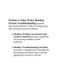
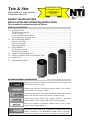
S-SR Series
S Series
SL Series
HAZARD SYMBOLS AND DEFINITIONS
Danger Sign: Indicates a hazardous situation which, if not avoided, will
result in serious injury or death.
Warning Sign: Indicates a hazardous situation which, if not avoided,
could result in serious injury or death.
Caution Sign plus Safety Alert Symbol: Indicates a hazardous situation
which, if not avoided, could result in minor or moderate injury.
Caution Sign without Safety Alert Symbol: Indicates a hazardous
situation which, if not avoided, could result in property damage.
Notice Sign: Indicates a hazardous situation which, if not avoided,
could result in property damage.
This Indirect Water Heater must be installed by a licensed and trained
Heating Technician or the Warranty is Void. Failure to properly
install this unit may result in property damage, serious injury to occupants, or possibly death.
Trin & Stor │ Installation and Operation Instructions
Indirect Water Heaters
1.0 INTRODUCTION
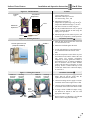
NTI offers three (3) diversified series of Indirect Water Heaters: "S" Series consists of a high performance
stainless steel tank and heat exchanger coil, "SL" Series offers a high mass stone lined tank and finned copper
heat exchanger coil, and "S-SR" Series consists of a stainless steel tank with dual heat exchanger coils. The S-SR
Series comes equipped with a Solar Domestic Hot Water backup via a second heat exchanger coil for boiler
supply connections ("S-SR" models). The "S-SR" series can also be used with a single boiler as a normal indirect
or with a second boiler for increased recovery rate. For the complete NTI Trin & Stor line, visit
www.nythermal.com.
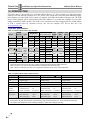
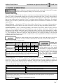
Trin & Stor Specifications
Table 1-1 Indirect Water Heater Specifications
Hour 1 Recovery 3 Boiler Coil Flow Coil
Continuous Rate
Storage
Weight (lbs)
(Gal @ Outlet Temp) Output
Model
Capacity Type
Rate
Drop (GPH @ Outlet Temp)
(US Gal)
Empty Filled 1 140 ° F
115 ° F (MBH) (GPM) (Feet) 140 ° F
115 ° F
S40
S50
40
53
S80
79
S120
119
S80SR
79
S120SR
119
SL35
35
SL50
50
SL70
70
Stainless
Steel
Indirect
71
90
485
655
228
238
303
313
146
146
6.9
6.9
1.0
1.0
196
196
271
271
115
995
356
468
210
10.4
3.0
292
404
157
1275
485
636
290
13.6
5.0
392
542
Stainless
Steel
Solar
Indirect
118
840
220
10.4
177
1190
290
13.6
Stone
Lined
Indirect
185
477
230
300
150
6.0
7.0
195
265
238
656
250
320
150
6.0
7.0
200
270
290
875
270
340
150
6.0
7.0
200
270
157 Upper 214 Upper
166 Lower 274 Lower
167 Upper 239 Upper
177 Lower 274 Lower
4.6
182 Upper 291 Upper
4.8
193 Lower 307 Lower
7.6
194 Upper 310 Upper
8.0
205 Lower 328 Lower
Notes:
1
Ensure the location chosen for the tank is capable of supporting the tank when filled with water.
2
Refer to Table 1-3 for a list of considerations when selecting a location for the tank.
3
Hour 1 Recovery based on 50oF inlet water temperature and 200oF boiler water outlet temperature.
Table 1-2 Indirect Water Heater Characteristics
Attribute
S Series
Tank
Coil
1
Insulation
Jacket
Recommended
Service
Clearances
Restrictions
S-SR Series
SL Series
stainless steel
stainless steel
stainless steel
stainless steel
stone lined
copper finned
EPS foam
grey plastic
top
connection side
boiler connections
MAWP
Max tank temp
Max boiler temp
EPS foam
grey plastic
top
connection side
boiler connections
MAWP
Max tank temp
Max boiler temp
EPS foam
grey plastic
Top
connection side
boiler connections
MAWP
Max tank temp
Max boiler temp
12"
12"
as required
150 psi
190oF
210oF
12"
12"
as required
150 psi
190oF
210oF
36"
12"
as required
150 psi
190oF
210oF
Notes:
1
Water used in the tank must meet the water chemistry limits specified in Table 2-1. Levels outside the limits may
corrode the tank and shorten its life resulting in damage to tanks and voiding the warranty.
2
Indirect Water Heaters
Installation and Operation Instructions
Trin & Stor
I.O.M. Checklists
The various Installation, Operation and Maintenance (IOM) Checklists contained in this manual are meant to be
read in conjunction with the details, drawings and safety information to ensure a complete and proper installation.
Pre-Installation Checklist 5
Inspection and Preparation
1. Remove packaging. Inspect for damage during shipping.
2. Package contents should contain the following:
Indirect Water Heater (verify correct model number)
Plastic lid, screws, and insulation (applicable to "SL" Series only)
Temperature and Pressure Relief Valve (150psi)
TPI Thermostat
Brass tee, ¾” (applicable to "SL" Series only)
Locating the Tank
1. Solid foundation, dry location, near boiler.
2. Leave room to service water heater and controls (coil can be removed from the top of the "SL" series tanks).
3. Sufficient room for boiler piping and servicing boiler.
4. Area free of flammable liquids or combustible vapors.
5. Install where leaks will not damage property.
6. Locate in room where temperature never drops below 50oF (10oC).
Water Damage Protection
1. Make provisions to protect the surrounding area from water damage should a leak occur from the tank, fitting
connections, or relief valve.
2. If the area surrounding the tank location is susceptible to water damage, install a catch pan c/w drain under the
tank.
General Information
1. Review system specifications and characteristics.
2. Know the Water Chemistry and Warranty requirements.
3. Be informed of potential hazards associated with DHW.
DOs & DON’Ts
1. DO NOT install water heater close to high temperature appliances or wood stoves as water heater jacket is
combustible.
2. DO NOT install where there is a risk of property damage in the event of an eventual leak at some
unpredictable time.
3. DO support the entire tank bottom with ¾" plywood (min) if elevating off the floor with blocks.
3
Trin & Stor │ Installation and Operation Instructions
Indirect Water Heaters
General Installation Requirements
Generalized instruction and procedures cannot anticipate all situations. For this reason, only a qualified installer
should perform the installation.
Users Responsibility – This manufacturer anticipates the proper installation and care in use of the product. As
with any hot water system, there is a risk of property damage and personal injury inherent in the use. NTI cannot
supervise the installation and therefore makes it a specific condition for the warranty that the customer will
supervise the installation and use of the product to be sure they are performed in accordance with the instructions
and I.O.M. Checklists in this manual. It is the User’s responsibility to maintain the appliance by having it
inspected on an annual basis, serviced as required, and to use the product for the purpose it was intended.
Installers Responsibility – A qualified installer is a licensed person who has appropriate training and a working
knowledge of the applicable codes, regulations, tools, equipment and methods necessary to install an indirect
water heater. The Installer assumes all responsibility for a safe installation and that it meets the requirements of
this document, as well as National and local codes.
Consider the following when selecting a location for the Indirect Water Heater: All tanks will eventually leak at
some unpredictable time, so take precautions and use a catch pan with a drain beneath the water heater to contain
potential leaks or install the tank in a location not susceptible to water damage. Do not install near a wood stove
where excessive heat could melt the water heater’s plastic jacket. Boiler supply piping, floor drain locations,
relief valve discharge will also need to be considered before selecting a location.
Scope of Instruction - This document pertains to the correct installation and operation of
the NTI Trin & Stor Indirect Water Heater line, exclusively series "S" and "SL". This
manual DOES NOT provide installation instructions for heating system boilers; therefore, installers must refer
to the boiler manufacturers instructions for boiler installation procedures.
Emergency Situation - Should the water heater be subject to flood, fire or other
damaging conditions, turn the power and water to the heater off. DO NOT place water
heater in operation again until it has been thoroughly checked by qualified service personnel.
Code Requirements - The installation of your NTI Trin & Stor Indirect Water Heater
must conform to the requirements in this manual, as well as National and local codes.
Intended Purpose - This appliance is not intended to convey or dispense water for
human consumption such as drinking or cooking.
Annual Service - Failure to have the Indirect Water Heater properly serviced and
inspected on a regular basis by a qualified service technician may result in property
damage, serious injury or death.
Flammable Vapors - DO NOT install this appliance in any location where gasoline,
flammable vapors or air-born contaminants are likely to be present.
Warranty Requirements - Improper installation, use, neglect or abuse of this product
may not only jeopardize the safe operation of this appliance but also void the warranty.
Be Informed - Read and understand this manual prior to proceeding with the installation
of the Trin & Stor Indirect Water Heater. Failure to follow the instructions outlined in
this document will result in property damage, serious injury or death.
4
Indirect Water Heaters
Installation and Operation Instructions
Trin & Stor
Safe Temperatures for Potable Water
Two factors used to determine safe hot water temperatures are Legionella and scalding. Potable water needs to
be stored at temperatures hot enough to limit the growth of Legionella, yet be cool enough to prevent scalding.
Since both hazards present a potential risk to the user, they must be monitored and controlled. Table 1-4
indicates how water temperature affects Legionella bacteria and contributes to scald injury. Use of a thermostatic
mixing valve in the indirect water heater plumbing system can help protect against both of these hazards. By
storing potable water at higher temperatures, bacteria growth is controlled, while still providing high temperature
water for dishwasher applications and low temperature water for bathing. Before proceeding, read the following
carefully and take all necessary precautions to avoid potential illness and/or injury that can result from
Legionella or scalding hazards.
Legionella Hazard - This bacteria is naturally occurring in surface water and ponds. It
can also be found in man-made water systems around the world such as water storage
tanks, water distribution systems, fountains, hot tubs, humidification systems, refrigeration systems and grocery
produce misters. Health authorities agree that Legionella bacteria most often enter the lungs due to aspiration
when contaminated water spray is breathed in as opposed to ingesting drinking water contaminated with the
bacteria. Typical illnesses attributed to Legionella include flue like symptoms (Pontiac Fever) and a potentially
fatal type of pneumonia (Legionnaires’ disease). Failure to follow instructions may result in illness or death.
Contributing Factors to Legionella - Experts acknowledge that Legionella is an identified risk in most water
systems. Although eradicating Legionella is improbable, precautions can be taken to control and monitor
conditions that promote bacteria growth. According to the World Health Organization (WHO); American
Society of Heating, Refrigeration, and Air-conditioning Engineers (ASHRAE); Canada Safety Council (CSC);
and Centers for Disease Control (CDC), contributing factors to the growth of Legionella in potable water
systems include:
• Minerals and nutrients present in the source water and systems materials
• Stagnation or low flow characteristic of dead ends in distribution piping systems and storage tanks
• Scale, corrosion, and bio film
• Tepid water in cold water lines
• Water storage temperatures optimal for bacteria growth
• Chlorine concentration
Scald Hazard - Hotter water increases the risk of scald injury. There is a hot water scald
potential if the storage tank thermostat is set too high. Before changing the temperature
setting on the tank thermostat, refer to the thermostat manufacturers recommended settings. Failure to follow
these instructions may result in serious injury or death.
A scald injury can occur when hot steam or liquid makes contact with one or more layers
of skin. Scald severity (degree of burn) is directly impacted by exposure time and
temperature. Refer to Table 1-4. The following basic precautions are common sense:
• Young children and elderly adults burn more quickly and should use cooler water.
• Never leave a child alone while drawing water in a bathtub.
• Test the water temperature before bathing or showering.
• Turn cold water on first, then add hot water until the temperature is comfortable.
Thermostatic Mixing Valve - When the system requires water at temperatures higher
than required for other uses, such as high temperature applications typically greater than
46oC (115oF), a means such as a thermostatic mixing valve shall be installed to temper the water for those uses
in order to reduce scald hazard potential. Anit-scald devices such as a thermostatic mixing valve allows potable
water to be stored at a higher temperature to limit bacteria growth, and allows water at the tap to be delivered at
a lower temperature to prevent scalds. Failure to follow these instructions may result in serious injury or death.
This appliance is not intended to convey or dispense water for human consumption such
as drinking or cooking.
5
Trin & Stor │ Installation and Operation Instructions
Indirect Water Heaters
Legislation and Guidelines - At the time this document was written, standards and
guidelines regulating the prevention of Legionella in the United States and Canada were
mostly voluntary. The American Society of Heating, Refrigerating and Air-Conditioning Engineers, Inc.
(ASHRAE) is currently in the process of converting its guideline entitled "Minimizing the Risk of Legionellosis
Associated with Building Water Systems" (ASHRAE Guideline 12-2000) into an official standard. Consult with
your local authorities as to recommended guidelines for controlling Legionella in potable water systems.
Storing water at temperatures >140°F may not be permitted in some States, so check with
the authorities having jurisdictions. In Canada, recent changes to the National Plumbing
Code requires that domestic hot water be stored at or above 61oC (140oF) and then mixed down to safe
temperatures at the tank outlet.
General Guidelines - In the absence of a National standard or local codes, the following are general guidelines
for “good practice” on maintaining, monitoring and operating your potable water system:
• Store domestic hot water at temperatures > 61oC (140oF).
• Store and distribute cold water at temperatures below 20oC (68oF).
• System supply for uses other than high temperature applications typically greater than 46oC (115oF) shall be
equipped with a thermostatic mixing valve on the hot water outlet to reduce potential scald hazards.
• Clean aerators and nozzles on water fixtures on a regular basis to reduce scale build-up.
• Clean storage tanks and remove sediment. Flush storage tanks and piping systems regularly for 10-30
minutes at high water temperatures (depending on guidelines used) to rid the system of sediment and scale
that develops, typically in the bottom of storage tanks where water temperature is coolest; and piping runs
where water can stagnate.
• Abandoned water lines should be capped off at the distribution main, not at the most convenient place.
• Avoid dead-ends in piping system. If unavoidable, provide a drainage port in these areas at the lowest point
to flush out stagnant water regularly.
• Insulate Domestic Hot Water recirculation lines and keep pipe runs as short as possible.
• Recommend annual water testing of water in your tank and piping system(s) to monitor water conditions.
• Keep a maintenance record of when your indirect water heater and storage tank were cleaned, piping
systems flushed and who did the service work.
Table 1-4 How Water Temperature relates to Legionella and Scald Hazard
Water Temperature 1
Legionella Bacteria 1
Water Temperature 2,5
Exposure Time vs Burn 5
158-176oF
70-80oC
Disinfection range
158oF
70oC
1 second - 2nd or 3rd degree burn
140-149oF
60-65oC
Bacteria die within minutes
140oF
60oC
5 seconds - 2nd or 3rd degree burn
o
o
o
o
122-131 F
50-55 C
Bacteria die within hours
131 F
55 C
5 seconds - 1st degree burn
68-113oF
20-45oC
Bacteria thrive and multiply
122oF
50oC
1 minute - 1st degree burn
below 68oF below 20oC Bacteria is dormant
111oF
44oC
5 hours - 1st degree burn 3,4
Notes:
1
Published by Chartered Institute of Plumbing and Heating Engineering, Databyte series, "Safe Hot Water Temperatures".
2
The elderly and small children are susceptible to bad burns at shorter exposure times than listed in this table.
3
A thermostatic mixing valve should be installed on DHW storage tanks when outlet temperatures exceed 115oF [46oC].
4
Typical water temperature for bathing or showering range between 98-113oF [37-45oC].
5
Temperature-Time-Burn Chart published by John Hopkins University, excluding notes.
6
Indirect Water Heaters
Installation and Operation Instructions
Trin & Stor
2.0 WATER HEATER PIPING
Failure to follow the instructions provided in this section will void your NTI warranty
and may result in property damage, fire, serious injury or death.
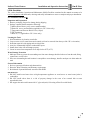
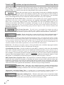
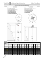
Domestic Side Piping
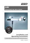
The various series of NTI Trin & Stor indirect water heaters are dimensioned and connection ports marked in
Figures 2-1 and 2-2. Dimensioned drawings are to be read in conjunction with Table 2-3 and 2-4 which identify
the connection type and port size and illustrates typical domestic water piping for a single indirect water heater.
Basic system components are identified in Table 2-2 and their function described in detail below. For multiple
Indirects, pipe the tanks in parallel using equal pipe lengths between each tank and a common tee to ensure
equalized draw.
Energy Efficiency - Although the NTI Trin & Store Indirect Water Heater is an energy efficient appliance,
insulating long pipe runs can improve the system efficiency by conserving energy and reducing standby losses.
System Preparation - Prior to connecting plumbing to the indirect water heater, flush the entire system to
ensure it is free of impurities that may be harmful to the system or indirect water heater. Check the water
composition of the domestic water supply prior to filling the tank to ensure the water characteristics are within
the range specified in Table 2-1. Water used in the tank must meet the water chemistry limits specified in Table
2-1. Levels outside the limits may corrode the tank and shorten its life resulting in damage to the tank and
voiding the warranty. If levels are outside the acceptable limits, consult a qualified water treatment expert about
treatment options for domestic water.
Damage to tanks resulting from water chemistry levels outside the ranges specified in
Table 2-1 can cause corrosion, shorten the life of the tank, and will void the warranty.
Table 2-1 Water Chemistry Requirements
Characteristic
"S" series
Min
Max
Min
Max
PH
Chloride (ppm)
6.0
8.0
0.0
80.0
"S-SR" series
"SL" Series 1
Min
Max
Min
Max
Min
Max
Min
Max
6.0
8.0
0.0
80.0
n/a
n/a
n/a
n/a
Notes:
1
The "SL" Series is not affected by abnormal PH or Chloride levels.
2
Residual solder flux can corrode stainless steel. Flush tank before heating
the domestic water in the tank or warranty will be void.
Flushing the
Water Heater
Many solder fluxes can severely
corrode stainless steel. Once piping
connections are completed, flush the
water heater by drawing at least three
(3) times the tank’s volume through
the water heater prior to heating
water in the tank. Failure to flush the
tank will void the warranty.
System Components - As a minimum, a properly installed system will include the following major components
identified in Table 2-2. It is the responsibility of the installing contractor and system designer to consider all
aspects of a proper system design including compliance with local codes, including additional components
required for prevention of thermal-siphoning (i.e. heat traps), isolation valves, drain and purge valves, etc.
Table 2-2 Domestic Side Major Component Checklist
Factory Supplied Components
Field Supplied Components
Indirect Water Heater
Temp & Pressure Relief Valve (150PSI)
TPI Thermostat
1
System Backflow Preventor 2
DHW (Potable Water) Expansion Tank 2,3
Thermostatic (Anti-Scald) Mixing Valve
Drain Valve
Notes:
1
All NTI Indirect Water Heaters come standard with a TPI thermostat control (not applicable for solar applications).
2
Check if required by local codes.
3
Expansion Tank is mandatory if using a System Backflow Preventor.
7
Trin & Stor │ Installation and Operation Instructions
Indirect Water Heaters
Indirect Water Heater - NTI Trin & Stor Indirect Water Heaters are equipped with a single-walled internal
heat exchanger coil. To maintain the efficient and reliable operation of the heat exchanger, and to avoid heat
exchanger failure, it is critical to ensure the rules and guidelines in this section are followed.
Locate the water heater in an area where leakage from the tank or plumbing connections
will not result in water damage to adjacent areas or lower floors. If such a location is
unavoidable, install a suitable catch pan with a drain under the appliance. This manufacturer is not responsible
for any water damage that may occur in connection with the indirect tank or any of its components.
Temperature and Pressure Relief Valve - Each Indirect comes standard with a factory supplied temperature
and pressure relief valve, sized to ASME specifications and compliant with Standard ANSI Z21.22•CSA 4.4
Relief Valves for Hot Water Supply Systems. The field installed relief valve and discharge piping is to be
mounted on the Indirect Water Heater in accordance with Figures 2-3 and 2-4 and must be accessible for
servicing or replacement. No valve is to be placed between the Relief Valve and the Indirect Water Heater or
Relief Valve and discharge pipe. Install discharge piping as shown in Figures 2-3 and 2-4 and in accordance with
Installation Checklist 2-1.
T&P Normal Operation - The relief valve is not intended for constant duty such as
repeated operation due to normal system expansion. If this occurs, correct the situation
by installing a properly sized domestic expansion tank as per the expansion tanks manufacturer’s instructions.
Location - Do not conceal, plug, or remove the relief valve from its designated point of
installation. Failure to comply may result in property damage, personal injury or death.
TPI Thermostat - The TPI is an immersion thermostat designed to allow a conventional water heater or boiler
to monitor and control the Indirect Water Heater’s tank temperature, improve response time, and prevent short
cycles of operation. Install the TPI on the Indirect tank as per the TPI Thermostat Wiring Instruction in Section
3.0 of this manual. For the Solar "SR" series, the TPI is only applicable when used as a normal indirect. For
controllers suitable for Solar Indirect applications, refer to the NTI Sol-R-Therm manual.
Drain Valve - The Indirect water heater requires a field supplied drain valve to facilitate emptying the tank for
inspection and servicing. Refer to Table 2-4 for drain port size and type.
System Backflow Preventor - Check if a backflow preventor (BFP) is required by local codes. Most plumbing
codes require a thermal expansion control device be installed if a backflow preventor, pressure reducing valve or
check valve is installed on a domestic supply line. If a backflow prevention device is used, then an expansion
tank is mandatory (not optional) and must be installed downstream of any device used to control system thermal
expansion. When using multiple indirects, check if a single BFP is required on the domestic supply or if each
tank requires it’s own backflow preventor and respective expansion tank. See Figures 2-3 and 2-4.
DHW ( Potable Water) Expansion Tank - This manufacturer recommends installing an expansion tank in the
domestic hot water system for the purpose of absorbing the increase in water volume caused by rising water
temperature. If required by local codes, the expansion tank must be suitable for use with potable water and be
sized in accordance with the water volume of the system and the firing rate of the boiler connected to the indirect
water heater. Refer to the expansion tank manufacturer’s literature for proper sizing information.
Isolation Valves – Ensure any valves installed between the expansion tank and indirect
tank inlet are left in the OPEN position during normal operation. Failure to follow these
instructions may result in discharge of the Relief Valve and result in property damage or personal injury.
Thermostatic (Anti-Scald) Mixing Valve - A mixing valve is recommended on branches supplying low
temperature water to endpoint plumbing fixtures when domestic hot water is stored above 46°C (115°F).
Temperature Limiting Device - When the tank requires water at temperatures higher
than 46°C (115°F), a mixing valve shall be installed to temper the water and reduce the
risk of scalding. Failure to follow these instructions may result in serious injury or death.
8
Indirect Water Heaters
Installation and Operation Instructions
Trin & Stor
Boiler System Piping
The NTI Trin & Stor line of high efficiency Indirect Water Heaters are intended to be heated by an external hot
water boiler where hot water supplied from the boiler is connected to ports 4 and 5 on the indirect tank, and
circulated through an internal heat exchanger coil in the tank. See Figures 2-3 and 2-4. The tanks are specifically
designed for low temperature applications [<100oC (210oF)] and are NOT intended to be used as a pool heating
system or in conjunction with steam boilers or other high temperature appliances where water temperatures could
potentially exceed 100oC (210oF). Refer to the Installation and Operation Manual included with the boiler for
detailed instructions on connecting boiler system piping to the indirect water heater.
High Temperature Applications - Trin & Stor Indirect Water Heaters are not to be used
for high temperture applications [greater than 100oC (210oF)] or in conjunction with
steam producing systems as this will void the warranty. Failure to follow these instructions may damage the tank
resulting in property damage, serious injury or death.
Solar System Piping
The NTI Trin & Stor "S-SR" line of high efficiency Solar Indirect Water Heaters is intended to be heated by a
solar thermal system where a propylene glycol mixture, heated by the solar collectors, is circulated through the
internal heat exchanger coil in the tank. This manual does not cover installation of solar thermal system piping. If
installing a Solar Indirect Water Heater as part of an NTI Packaged Solar Domestic Hot Water System, refer to
the NTI Sol-R-Therm Manual for detailed instructions regarding Solar System Piping.
Domestic side piping for solar thermal can be done in a number of configurations depending on the application.
Since solar tanks are specifically designed for high temperature applications in the event of collector stagnation
and overheating, tank sensors specifically designed for these high temperature applications must be used instead
of the TPI.
TPI Applications - The TPI thermostat control is compatible with any Trin & Stor tank,
including "S-SR" models, when used as normal indirect water heaters. The TPI is not
intended for use with Solar Domestic Hot Water Systems. An alternate sensor and thermostat control, normally
provided with the solar thermal system, should be used.
Pre-heat Option - The most common application is where the solar water heater is plumbed in series with an
auxiliary water heater which is used as the primary storage tank. The hot water out (connection port 2) of the
solar water heater is connected to the cold water inlet of the auxiliary water heater, so when there is a demand for
domestic hot water, the auxiliary water heater immediately brings in pre-heated water from the solar tank to
replace it instead of cold water directly from the potable water system. In this configuration the upper heat
exchanger coil is not required so connection ports 4 and 5 should be capped or plugged with a brass fitting. Refer
to Figure 2-4 and Table 2-1 respectively for location and sizes of connection ports for applicable solar models.
Back Up Option - This option is used when the solar water heater is the primary storage tank and solar water
heating alone is not enough to meet the domestic hot water demand. Hot water supplied from the boiler is
connected to ports 4 and 5 on the solar water heater and circulated through the upper heat exchanger coil in the
tank. See Figure 2-4. Refer to the Installation and Operation Manual included with the boiler for detailed
instructions on connecting boiler system piping to the indirect water heater.
Storage Option - This option is used when the solar water heater is the primary storage tank and is connected to
an additional storage tank for use as extra storage or as a dump zone for excess heat. In this method, hot water
from the solar water heater is transferred to the secondary storage tank using connections 4 and 5. Note that flow
direction is reversed for this application compared to the back up option. See Figure 2-4.
9
Trin & Stor │ Installation and Operation Instructions
Indirect Water Heaters
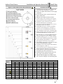
Figure 2-1 Indirect Water Heater Dimensions
Table 2-3 Indirect Water Heater Dimensions
Model
A
B
C
D
E
F
S40
S50
56
49
3
3
3
1
1
S80
70 1/4
70 1/4
43 1/4
43 3/4
48 3/4
S120
S80SR
S120SR
SL35
SL50
SL70
10
Dimensions (inches)
G
H
I
1
54 /4 46 /4 46 /4 29 /8 25 /8 26 /8
3
5
47 3/4 39 3/4 39 /8 29 /8
26
27
69
64 3/4
68 7/8
64 3/4
40 1/4
40 3/4
45 3/4
60 7/8
53 5/8
59 1/2
52 3/8
43 1/2
44
49
60
35
1
53 /4 44 5/8
59 1/2 35 1/8
52 3/8 31 3/8
43 1/2
44
49
-
29 5/8
40 5/8
56 1/2
49 1/4
43 1/8
43 5/8
48 5/8
30 5/8
41 5/8
21 3/4
22 1/2
13 7/8
13 7/8
13 7/8
3
9 /8
9 7/8
1
2 /8
2
3
10 3/4 2 /8
3
1
12 /4 2 /8
42 1/4
2
1
35 /8
2
43 3/8 43 1/4
43 7/8 43 3/4
48 7/8 48 3/4
J
K
L
M
N
1
1
-
-
-
2 /8
2
20 /8
23 7/8
2 3/8
2 3/8
2
2
7 7/8
7 7/8
7 7/8
23 7/8
7
28 /8
23 7/8 26 1/8 9 7/8 50 1/2
28 3/4 57 5/8 11 1/2 46 1/8
22 1/4
26
28
-
Indirect Water Heaters
Trin & Stor
Installation and Operation Instructions
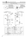
Figure 2-2 Solar Indirect Water Heater Dimensions
1.
2.
3.
4.
Installation Checklist 5
Install domestic side piping as per National and
local codes. Refer to Figures 2-3 and 2-4.
Do not over tighten brass threads on water supply
connections.
Do not apply heat to the cold water inlet on the
indirect water heater.
Mark the water supply for future reference.
5. Install a mixing valve on the hot water outlet of
the water heater as shown in Figure 2-3 and 2-4.
6. Install boiler water connections (if used) as per
the boiler manufacturer’s instructions.
7. Cap (plug) any unused connection ports, such as
domestic hot water recirculation.
8. Install T&P relief valve on tank in accordance
with local codes and Figures 2-1 through 2-4.
9. Ensure no valve is installed between the relief
valve and indirect water heater or discharge pipe.
10. Ensure discharge piping material used is rated to
withstand temperatures up to 250oF (120oC).
11. Direct discharge to a safe area (drain) where hot
water or steam will not cause damage or injury.
12. Terminate discharge pipe 6"-12" above the floor.
Do not connect discharge pipe directly to a drain.
13. Typical discharge pipe diameter ¾". Maximum
pipe length is 15 feet with 2 or less elbows.
14. Cut discharge end of pipe at a 45o angle to reduce
the risk of being blocked or capped.
15. Install drain valve in the location and orientation
shown in Figures 2-3 and 2-4.
16. Verify with local codes if a backflow preventor or
thermal expansion control device is required.
17. Install a domestic expansion tank downstream of
the backflow preventor (control device).
18. Install the domestic expansion tank on the cold
water supply of the domestic side piping.
19. Flush the tank thoroughly before filling to heat
water. Fill heat exchanger coil with heating fluid.
Table 2-4 Indirect Water Heater Connections
Model
T&P RV Hot Out
1
S40
S50
S80
S120
S80SR
S120SR
SL35
SL50
SL70
3
/4" F
3
/4" F
3
/4" F
3
/4" F
1" F
1" F
-
Recirc
2
3
3
/4" F
3
/4" F
1" M
1
3
1 /2 " M
/4" F
1
3
1 /2 " M
/4" F
1
1 /4 " F
1" F
1
1 ¼" M 1 /4" F
3
/4" M
3
/4" M
3
/4" M
1" M
Connection Port Sizes
Boiler In Boiler Out A-stat Lw Cold In
Drain
Solar In Solar Out A-stat Up
4
5
6
7
8
9
10
11
1" M
1" M
Well
1" M
-
-
-
-
1" M
1" M
Well
1" M
1
-
-
-
-
-
-
/4" M
/4" M
Well
1" M
1" M
Well
1 /2 " M
1" M
1" M
Well
1 /2 " M
1
-
Well
1" M
-
3
Well
1 /4 " M
1
-
3
3
3
3
3
/4" M
/4" M
3
/4" M
3
/4" M
3
/4" M
/4" M
/4" M
3
/4" M
3
/4" M
3
/4" M
Well
Well
Well
-
/4" M
/4" M
3
3
3
3
-
-
Well
-
3
3
-
-
-
-
-
-
/4" M
/4" M
3
/4" M
/4" F
/4" F
3
/4" F
* Connections are NPT unless noted otherwise. All Aquastat connections are friction fit immersion wells.
11
Trin & Stor │ Installation and Operation Instructions
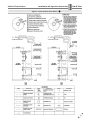
Figure 2-3 Indirect Water Heaters
Domestic Plumbing Schematic
12
Indirect Water Heaters
Indirect Water Heaters
Installation and Operation Instructions
Trin & Stor
Figure 2-4 Solar Indirect Water Heaters
Domestic Plumbing Schematic
13
Trin & Stor │ Installation and Operation Instructions
Indirect Water Heaters
3.0 FIELD WIRING
Ensure all field wiring complies with this manual and is installed in accordance with the National Electrical
Code ANSI/NFPA 70 or Canadian Electrical Code CSA C22.1, and any applicable local codes.
TPI Thermostat Wiring
24VA Transformer (Hot, GND) - The TPI requires a 24VAC power supply to function. This power supply
may be provided directly from the boiler (check with boiler manufacturer’s instructions) or via a field provided
24VAC transformer. See Figured 3-6 to 3-9. Note the TPI may draw up to 0.6 W
Pump/TT Output Contacts - The TPI is equipped with a normally open isolated end switch (Pump/TT) that
closes when the tank temperature drops below the TPI setting. Connect the Pump/TT contact to the DHW
specific input on boilers equipped with DHW priority capabilities (Figures 3-6 to 3-7) or to the priority zone
input on zone controllers Figure 3-9. Alternately, the Pump/TT contact could be used to power a zone valve, see
Figure 3-8. Note the Pump/TT contact is rated for 125V@10A.
Install the TPI Thermostat in accordance with these instructions, the installation checklist(s) in this section, and
corresponding Figures 3-1 to 3-5.
TPI Applications - The TPI thermostat control is compatible with any Trin & Stor tank,
including "S-SR" models, when used as normal indirect water heaters. The TPI is not
intended for use with Solar Domestic Hot Water Systems. An alternate sensor and thermostat control, normally
provided with the solar thermal system, should be used.
Avoid Shocks - To avoid electrical shock, turn off electrical power prior to opening any
electrical box on the unit. Ensure the power remains off while any wiring connections are
being made. Failure to follow these instructions may result in component failure, serious injury or death.
Wire Protection - When passing 110VAC wiring through the TPI housing, the installer
must use appropriate conduit and a chase nipple to secure the wiring and prevent chafing.
Failure to follow these instructions may result in serious injury or death.
Component Damage - DO NOT use the TPI if it has been under water. Failure to replace
electrical damaged components may result in component failure, serious injury or death
14
Indirect Water Heaters
Installation and Operation Instructions
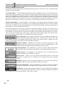
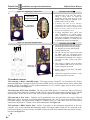
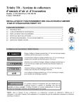
Figure 3-1 TPI Thermostat
Indicator
Light
Trin & Stor
Features
y Dimensions 5.0"H x 2.6"W x 1.7"D
Temperature
Adjustment
Control voltage 24VAC
Maximum control power 0.6 W
TT contact rating 125V, 10A
o
y Adjustment increment 1 F.
Cover
Differential
Adjustment
Temperature set point range 110oF to 160oF.
Temperature differential range 5oF to 20oF.
10k sensor accurate to within 2 degrees.
y Fits any standard immersion well, no special
adapter required. Mounts to tank using self
taping screw provided.
y Indicating light provides status of power, call
Sensor
for heat, up to temperature, normal operation
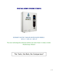
Figure 3-2 Installing the Sensor
Fit flush against the tank
(complete installation)
Screw A
2. Mount the TPI flush against the tank.
TPI
3. Use the self-tapping screw provided (Screw
A) to attach the TPI to the exterior of the
tank.
Tank
Wall
Sensor
Sensor
Incoming
Terminals
(24VAC)
PUMP / TT
Terminals
(110VAC)
4. Slide the temperature sensor all the way into
the immersion well until it contacts the end.
The sensor will measure temperature
adequately by resting against the bottom of
the immersion well. A complete installation
does not need the sensor to make intimate
contact with the entire well surface to work
properly. Sensor is soldered directly to TPI
so DO NOT bend sensor connection sharply
or overwork it.
Installation Checklist 5
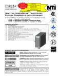
Figure 3-3 Wiring the Controls
PUMP / TT
Terminals
(24VAC)
Installation Checklist 5
1. Place the hole located in the back of the TPI
over the immersion well.
Incoming
Terminals
(24VAC)
5. Turn off electrical power supply to water
heater. Run all 24VAC wiring thru the
square notch in bottom of TPI case.
6. Connect incoming 24VAC supply to 24VAC
Terminals on the bottom right corner of TPI.
7. Connect 24VAC PUMP/TT outgoing wiring
to terminals on the bottom left corner of TPI.
Close
Nipple
Square
Notch
Conduit
To Circulator
8. If using 110VAC PUMP/TT output wiring,
use knockout at bottom of TPI case with
appropriate chase nipple.
9. Refer to Figures 3-6 through 3-9 for TPI and
Boiler control configuration drawings.
15
Trin & Stor │ Installation and Operation Instructions
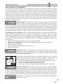
Figure 3-4 Adjusting the Temperature
SCALD DANGER
SEE MANUAL
BEFORE REMOVING
Temperature
Setting Slide
Indirect Water Heaters
Installation Checklist 5
10. Locate the temperature setting slide on the
right-hand side of the TPI. The Factory
setting is 120oF (49oC). To adjust the
temperature setting, slide the lever to the
desired setting using the indicator scale.
Normal range is 100oF to 140oF.
11. If domestic hot water is to be stored at
temperatures above 115°F (46°C), an antiscald mixing valve shall be installed on the
tank’s hot water outlet to mix the water
down to safe temperature levels.
12. If setting temperature above 140oF, read
"Safe Temperatures for Potable Water"
before removing the SCALD DANGER
label on the temperature slide. Higher water
temperatures mandatory in Canada may not
be permitted in certain US jurisdictions.
Figure 3-5 Operation and Differential
Installation Checklist 5
13. Locate the differential setting slide on the
left-hand side of the TPI. Factory setting is
10°. Slide the lever to the desired setting,
using the indicator scale.
14. The TPI will close the output contact (call
for DHW) when the temperature drops
below the setting minus the differential. A
small differential with high water setpoints
can result in boiler cycling and reduce
efficiency.
Differential
Setting Slide
15. Once wiring is complete, turn on electrical
power. Indicator light at the top of the case
will be solid green if powered.
16. Replace TPI cover and secure with Black
Screw provided.
17. Check water temperature at faucet to verify
desired temperature is achieved.
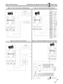
TPI and Boiler Controls
TPI connected to Boiler with DHW Input - TPI output contacts "Pump/TT" are connected to the boiler’s
dedicated DHW input. Typically the boiler will achieve DHW priority via circulator control (refer to boilers I&O
manual). 24VAC is provided by a field supplied transformer or via a 24VAC supply from the boiler (refer to
boiler I&O manual). See Figure 3-6.
TPI connected to NTI Trinity LX Boiler - The LX provides DHW priority. To connect the TPI to an LX boiler,
wire the TPI 24VAC input to LX contacts "COM" and "R"; connect TPI output contacts (Pump/TT) to LX DHW
input terminals, "DHW" and "Sensor COM". Refer to boiler application manual, Appendix B. See Figure 3-7.
TPI connected to Zone Valve - Typically used in applications where the boiler does not accept a dedicated
DHW input. 24VAC is provide by a field supplied transformer or via a 24VAC supply from the boiler (refer to
boiler I&O manual), TPI output contacts "Pump/TT" complete 24VAC to a zone valve. Zone valve end switch is
connected to boiler heat (T-T) input, refer to boiler I&O manual. See Figure 3-8.
TPI connected to DHW Priority Zone - 24VAC is provided via the transformer incorporated in the zone
controller, refer to zone controller I&O manual for details. TPI output contacts "Pump/TT" are connected to the
priority zone input (e.g. Zone 4). Priority for DHW is achieved via the zone controller when the priority switch is
activated. See Figure 3-9.
16
Indirect Water Heaters
Installation and Operation Instructions
Trin & Stor
Figure 3-6 TPI wired to Boiler with DHW Input
Figure 3-7 TPI wired to NTI Trinity LX Boiler
Figure 3-8 TPI wired to Zone Valve
Figure 3-9 TPI wired to DHW Priority Zone Controller
17
Trin & Stor │ Installation and Operation Instructions
Indirect Water Heaters
4.0 START UP AND CHECK OUT
Filling the Water Heater
1. Thoroughly flush the water heater so that three (3) times the tank’s volume has been drawn through it.
2. Verify water connections completed.
3. Close drain valve. Open highest hot water faucet.
4. Open cold water inlet valve and fill system.
5. Fill until a steady stream of water flows from the faucet.
6. Close the hot water faucet.
7. Ensure the boiler and domestic piping is free of leaks before proceeding to operational checklist.
Operational Checklist 5
1. Ensure all electrical connections are made correctly and no high voltage wires are exposed.
2. Set the TPI immersion thermostat (aquastat) to the desired temperature.
3. Verify that there is power to the TPI Thermostat Control.
4. Ensure that the tank is filled with water.
5. Ensure that the tank’s heat exchanger coil(s) are filled with water or heat transfer fluid.
6. Ensure piping system is free of leaks and that air has been purged from system.
7. Initiate a call for domestic hot water by opening hot water taps on domestic water fixtures.
8. Verify that the boiler starts when the aquastat calls for heat and shuts down when water heater is satisfied.
9. Verify circulator and zone valve operation during an aquastat call for heat and DHW priority. Allow zones to
operate long enough to purge any remaining air from the system.
10. Check for proper operation of relief valve by opening it manually.
11. If T&P relief valve functions continuously during normal thermal expansion, the expansion tank may need to
be upsized.
5.0 ANNUAL MAINTENANCE AND INSPECTION
Inspection Checklist 5
1. Perform a visual inspection of all valves, drains, and system piping for signs of leaks.
Maintenance Checklist 5
1. Verify maximum water temperature at hot water fixtures to verify mixing valve temperature settings.
2. Manually operate T&P relief valve by moving lever to open position until hot water is released and allow it to
snap close. If closed relief valve continues to leak, close cold water inlet, drain tank, and replace relief valve.
3. If T&P relief valve functions continuously during normal thermal expansion, the expansion tank may need to
be upsized.
4. Ensure that boiler and/or solar thermal system is maintained in accordance with their installation manuals.
5. Check function of field-installed controls, thermostats, and circulators.
6. Check tank PH and chloride levels to determine if water chemistry is within the specified range.
7. Any additional procedures required by local codes.
Draining the Water Heater
1. Disconnect the power supply to the heat source.
2. Close the cold water supply shut off valve.
3. Allow appliance to cool before servicing to avoid burns.
4. Open the drain valve and divert water in tank to alternate storage location or floor drain.
5. Open highest hot water faucet to allow air to enter the system.
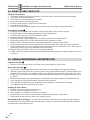
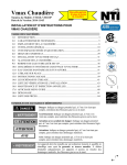
Reinstalling the Heat Exchanger - The "SL" Series of indirect water heaters has a removable heat exchanger
coil which can be accessed from the top of the unit. Refer to Figure 4-1 and corresponding installation checklist
for instructions on reinstalling the coil.
18
Indirect Water Heaters
Installation and Operation Instructions
Trin & Stor
Installation Checklist 5
Figure 4-1 Reinstalling the SL Series Heat Exchanger
1. Turn off power to unit and heat source.
2. Shut off water supply to tank and boiler.
3. Allow appliance to cool before servicing.
4. Remove heat exchanger coil from the tank.
5. Flush inside of heat exchanger with water.
6. Rinse outside of heat exchanger with water
and scrub with soft bristled brush.
7. Install heat exchanger. Ensure o-ring
housing is installed properly.
8. Complete the following steps, 9 through 12,
to reinstall the coil plate.
9. Place the nut beneath the flange opening.
10. Hold the nut in place with one hand - insert
the bolt with the other.
11. Be sure to place bolts in all of the openings.
12. Thread the bolt into the nut and tighten in
proper sequence as shown. Excessive force
is not required to seal properly.
13. Turn on the water and bleed the air from
the system.
6.0 PARTS LIST
Table 6-1 Indirect Water Heater
Item Part # Models
All Series (S, S-SR,
1
84156
All Series (S, S-SR,
2
84158
S )
3
84217
SL-35,
SL-50
4
84218
SL-70
5
84219
SL Series
6
84220
SL Series
Description
Relief Valve, T&P, ¾", 150 psi
Controller, Water Heater, TPI
Coil, 35/50 Gal
Coil, 70 Gal
O-ring 6 1/4" ID for Coil
O-ring 6 3/4" ID for Coil
Trin & Stor parts available
at any stocking wholesaler.
Installers needing technical
assistance can contact NTI
directly at 1-800-688-2575.
7.0 TROUBLESHOOTING
Locate the TPI indicator light at the top of the case as shown. Refer to Table 7-1 for TPI troubleshooting guide.
Figure 7-1 TPI Thermostat
Indicator Light
Indicator Light Status
Unlit
No power to unit.
Solid Green
Powered.
Temperature is in range.
No demand. Demand satisfied.
Pump/TT output should be open.
Flashing Green Calling for heat.
Temperature is out of range.
Pump/TT output should be closed.
Flashing Red
TPI has sensed failure.
Replace TPI module.
19
NY Thermal Inc. 65 Drury Cove Road Saint John, NB E2H 2Z8 Canada
Technical Assistance: 1-800-688-2575
Website: www.nythermal.com
Fax: 1-506-432-1135