1
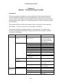
Section 4: Solar Water Heating
System Troubleshooting presents
structured methods to follow in diagnosing
and correcting system problems.
• Module: Problem Assessment and
System Checkout provides guidelines
for assessing installed system
problems.
• Module: Troubleshooting Checklist
provides a comprehensive checklist for
determining probable causes and the
appropriate corrective actions.
Problem Assessment and System Checkout
Section 4
Module: Problem Assessment and System Checkout
I.
PROBLEM ASSESSMENT
To diagnose system problems, you must not only understand the system type and its
components and how they work, but you must also know what questions to ask to
determine the problem and find out when and why it occurred. The more experience you
have servicing solar systems, the more you will learn what questions to ask the customer.
The Initial Service Call
When you first receive a service call, record the caller’s name, address and telephone
number and be sure to get directions to the service location. Also, verify the caller is the
system owner and is authorized to have you service the system.
Determine what kind of service the caller is requesting. Is it a routine service call or is the
system not working properly? If the system is not working, what exactly is wrong? Is
there no hot water? Is the system leaking? If it is leaking, where is the leak – on the roof
or at the storage tank? The more you know about the system, the better prepared you will
be when you arrive at the site. For example, if the system has an expansion tank and the
system is over two years old, you will want to take new glycol with you to replace the old
glycol. If the system has a drainback tank, you will want to have distilled water with you.
Avoid any misunderstanding by making your payment policy clear at the outset. For example, if the caller is renting the home, clarify whether or not you expect to be paid at the
time service is rendered.
Find out the type of system, who installed it, how old it is and what previous service has
been performed. Also, find out if the caller has a manual, a schematic, and a parts list for
the system and what, if any, service contracts, warranties and insurance policies cover the
system or its components.
System Records
All collectors and systems sold or manufactured in the state of Florida must be certified
by the Florida Solar Energy Center (FSEC) in Cape Canaveral. As part of the
certification requirements, each system must include a homeowner’s manual that lists
system components and describes the system design, operation and maintenance
requirements. In addition to the manual, each system should have a freeze protection
information label displayed at a prominent location on the system – on the storage tank,
heat exchanger or controller. This label describes the system's freeze protection
mechanism and any actions the homeowner must take when freezing occurs.
4-1
Problem Assessment and System Checkout
Information pertaining to a specific FSEC certified system can be obtained by contacting
FSEC at http://www.fsec.ucf.edu.
The Solar Rating and Certification Corporation (SRCC), a national solar collector and
system certification agency certifies many systems sold throughout the United States.
Information pertaining to a specific SRCC certified system can be obtained by contacting
SRCC at http://www.solar-rating.org/.
Warranty Coverage
Find out if the system or its components are covered by warranties. Typically, the term of
the collector warranty will be from 5 to 20 years, with other components varying from 90
days to 5 years. It is also important to know whether the warranties are full or limited.
This designation is required to appear on the warranty document. A full warranty is
required by law to provide the following:
•
•
•
•
•
A defective product will be fixed (or replaced) free, including removal and
reinstallation if necessary.
The product will be fixed within a reasonable time after the customer complains.
The customer will not have to do anything unreasonable to get warranty service
(such as shipping components back to the factory).
The warranty is good for anyone who owns the product during the warranty
period.
If the product cannot be fixed (or has not been after a reasonable effort to do so),
the customer may choose to receive a new product or a refund.
Limited warranties provide less protection than the full warranty. For example, a limited
warranty may:
•
•
•
•
•
Cover only parts, not labor
Allow only a prorated refund on credit
Require the customer to return the product to the manufacturer for service
Cover only the original buyer
Charge for handling the service order
Be aware, too, that some companies include a provision that unauthorized service may
void their warranties. In these cases, be sure to contact the manufacturer for approval. If
you provide unauthorized service, you may be held liable and be forced to take over that
warranty.
Typically, a solar water heating system has a system or installation warranty separate
from the individual component manufacturer warranties. Be prepared to explain this to
the customer if necessary. Some service problems that arise during the warranty period
may not be covered by the warranty for the item in need of repair or replacement. For
example, if a component fails because of faulty installation rather than a product defect,
the manufacturer of the product may not be required to repair the component. In this case,
4-2
Problem Assessment and System Checkout
the contractor’s system warranty, if still in force, should cover the cost to repair the
problem.
Another potential gap in warranty coverage falls in the area of freeze damage. Some
collector warranties will specifically exclude damage as a result of freezing. In addition,
the freeze protection component will typically exclude coverage of incidental damages. If
the freeze protection device fails, causing damage to the collector, this exclusion
normally relieves the manufacturer of the component of liability for repair or replacement
of the collector. The customer can usually seek recourse from the homeowner’s policy to
recover these costs.
If the customer has warranties that appear to be in force, but the company is no longer in
business, all hope is not necessarily lost. If the system was financed, the finance company
may be liable for all warranty claims as a “holder in due course.” A review of the
installment sales contract will usually specify what rights the customer may have in this
regard.
Even when the warranty is no longer in force, some contractors replace components at no
cost as a goodwill gesture toward the customer. But they are not obligated to absorb this
expense. Ask about warranties at the outset so neither you nor the customer is surprised
when you prepare the repair estimate.
Service History
Many contractors offer service contracts to their customers, providing either the labor or
materials for free, depending on the type of contract. So it is important to determine
whether or not you are doing something you do not need to do because the customer has
a service contract with another company.
Find out about past service and repairs on the system. If you know a system is five years
old, you may think the controller is no longer under warranty. But if the controller was
replaced just 90 days ago and is under a one-year warranty, you can take the controller
back to the supplier for exchange. The customer will appreciate not having to pay for
another controller and will call you back the next time service is needed.
Contractor Liability
Some contractors give customers advice over the telephone about how to correct a
problem. If you do this, be aware of potential liability. For example, pushing the reset
button on the storage tank is a very simple procedure, and you may suggest that your
customers do this themselves. It saves you time and saves them the cost of a service call.
But tell them first to turn off the circuit breaker. Emphasize that they should never
remove the front plate on the tank until they have turned off the power.
4-3
Problem Assessment and System Checkout
You might rather not give any instructions over the telephone. Even if you only need to
reset the heater you can make the visit worthwhile for the customer and for yourself by
performing a routine service check while you are there.
Overall Checkout
You should always check the entire system while you are on a service call because many
times more than one problem exists. For example, you may replace a defective pump.
Later, when this new pump also fails, you find that a defective valve was preventing
water from getting to the pump, causing the pump failure. Keep in mind that a “system”
requires proper performance of all the components working together.
While you check the system, consider ways you can improve its performance. For
example, open-loop systems can include an air vent, a vacuum breaker, a pressure relief
valve and a freeze valve. You will find many direct systems do not have all of these
components, even though each one has a definite function. You can give the customer a
better working system by adding these useful components.
At the same time, do not change the system for change’s sake. Some contractors do not
like or do not understand controllers or PV systems. So rather than make repairs, they
change the whole system. If you do not want to work on one type of system, refer the job
to someone else.
When you first look at a system, prepare an estimate for the customer including the cost,
the results and the benefits of the repairs. After you complete the repairs, test the system
completely once again. Be sure that it is right. If you have to go back on a second or third
call, you lose whatever money you made on your first call. And finally, point out your
work so the customer knows what you have done.
Investigating Consumer Complaints – An Example
Suppose a collector loop pipe has burst, but the customer manually drained the system to
prevent freeze damage. The collectors were drained using the proper isolation and drain
valves; yet the next morning water was trickling from the collector and a pipe was
ruptured. Somehow water had gathered in the collector. You should check several
possible causes.
First, is the homeowner sure all the water was drained from the collector? Is the system
installed to prevent water being trapped when the collectors are drained? Investigation
reveals the system contains a vacuum breaker at the collectors and the drain valves are
installed in such a manner that one is at a higher level than the other. You determine the
amount of water the homeowner says was drained represents what would have been in
the collectors and piping – unless, of course, there is a small water trap in the collector or
collector piping. If the collector is large and mounted in a horizontal position, are the
flow tubes bending in the midsection (creating a water trap)? Investigation reveals no
trap.
4-4
Problem Assessment and System Checkout
There could be another culprit – the isolation valve. Although the valve was closed by the
homeowner, sedimentation build-up or a malfunction could have caused the valve to leak,
allowing water to slowly seep to the collectors, freeze and rupture the pipe.
Lifestyle Analysis
Some people think when they acquire a solar DHW system, they have an unlimited
supply of hot water. Be sure they understand the DHW system storage can provide the
hottest water during the late afternoon and early evening hours. Keeping this in mind,
they should use hot water during these periods to achieve the best results from the
system. To minimize their back-up heating expense, they could, for example, take
showers and use the dishwasher during the evening and use only small amounts of hot
water in the morning. Here are some questions that you may want to ask if the complaint
is “not enough hot water” or “high electric use”:
1. How many people are using the hot water?
2. Have recent guests added to the water use? How many guests?
3. Have extra washing (clothes or dishes) demands recently been put on the system?
4. When is the family’s major use of hot water?
5. Has the weather been clear, allowing the maximum solar heating? Or has it been
overcast, especially around the middle of the day?
6. Are water bills higher than usual (perhaps indicating a leak in the system – perhaps a
leak under the slab)?
Note: Remember, this is only a sample of the questions service personnel might ask.
II. COMMON PROBLEMS
Some common problems are easy to identify and correct. Other problems, such as “not
getting enough hot water” require investigating numerous components, the system design
and location, as well as the homeowners’ lifestyle. This section first discusses problems
that are easy to identify and then describes problems that demand more investigation. A
detailed and concise listing of these problems, the components to check, the possible
causes, and the corrective actions are listed in Section 4, Module: Troubleshooting
Checklist.
The simplest way to find out if the system is working is by turning off or disconnecting
the electric back-up element (or other source of back-up heat). Some installers provide a
switch near the storage tank for this purpose. In most cases it is necessary to turn off the
appropriate circuit breaker at the electrical load center.
4-5
Problem Assessment and System Checkout
Certain symptoms are obvious, but you may find more than one problem. Therefore, once
you identify the initial symptoms, continue the diagnostic procedure.
Before you begin the diagnostic procedure, ask the owners to describe any symptoms
they have noticed (for example, insufficient hot water, pump running at night, noisy
pump or leaking collectors). Use this information and the Troubleshooting Checklist
Module to quickly identify the causes. Then follow this procedure to identify other, less
obvious problems.
The most common problems are related to the following:
•
•
•
•
•
•
Controls and sensors
Pumps and flow rates
Thermosiphoning and check valves
Freeze damage
Collector shading
System sizing and consumer lifestyle
Controls and Sensors
If the pump operates constantly or does not operate at all, the problem may be in the
control system.
The controller itself, a sensor or the wiring might have been damaged by lightning
strikes, line voltage surges or short circuiting from water, rust or abrasion. Each of these
components should be examined. But if the pump does not operate, the problem could
also be in the pump itself or the piping.
Pumps and Flow Rate
If the system controls are working correctly, an inoperative pump may be due to a stuck
impeller, a burned-out motor or a broken shaft. These types of problems may be expected
over the lifetime of any component subjected to the temperature and cycling stresses of a
solar system pump.
Even though a solar pump is operating and is being controlled correctly, there still may
be problems with the actual flow rate in the collector loop. If the pump has been sized to
just barely overcome the pressure head of the collector loop, an unexpected added
resistance can stop all flow through the collector. For example, air in the fluid may, over
a period of time, collect in a section of piping, especially if it cannot escape through a
vent to the atmosphere. This "air lock" can prevent any flow if the pump does not have
the capacity to compress the air completely and force it through the system.
In an indirect system, loss of collector fluid pressure can also prevent flow in the
collector loop. The pump is generally not sized to overcome the static head or pressure
4-6
Problem Assessment and System Checkout
due to the difference in height between the top and bottom of the collector loop. It is
usually sized to maintain the desired flow against the dynamic head or pressure due to the
resistance to flow in the pipes, fittings and valves. If the fluid pressure to overcome the
static head is lost, then the pump may not be able to maintain flow against the combined
static and dynamic head of the system.
Thermosiphoning and Check Valves
As the liquid in the active system collector loop becomes cooler in the evening or in
colder weather, it becomes denser and heavier, flowing down into the storage tank. In
turn, it forces less dense, heated liquid up into the collector where this heated liquid
cools. This action, if not stemmed with a properly operating check valve, can result in
excessive loss of heat. In addition, this action often deceives the collector sensor and
controller into believing the collector is hot and thereby activating the pump
intermittently during the evening and colder nights.
The most common check valve utilized in active solar systems is the vertical ring check
valve. Unfortunately, scale and sedimentation build up over time may prevent this valve
from seating completely. Defective valves must be cleaned of all sedimentation and
corrosion or replaced. A simple and relatively accurate method of determining if the
check valve is defective is to check the operation of the pump at night. If the pump is
turning on and off (on differential controlled systems), leaking through the check valve
and thermosiphon heat loss is indicated.
Freeze Damage
Burst collector tubes and piping are a result of an improperly functioning freeze
protection system. In a differential controlled system, the fault may lie in the freeze
sensor operation, in the sensor’s location or in the controller itself. If the system has a
freeze sensor but no freeze protection valve, a power failure during a freeze could result
in pipe rupture. It is not uncommon to have a power failure during a freeze.
In a system using an automatic freeze prevention valve, the valve or its location may be
at fault. This type of valve often fails to reseat properly after opening. Extreme
temperatures during summer conditions can affect the calibration and internal
components of the valve, which in time may lead to failure or leakage. A leaking valve
should be removed, serviced and recalibrated per manufacturer’s recommendations or
replaced to ensure proper operation during the winter season.
Freeze damage can also occur when the collector is “drained.” (Some systems have
“traps” in the piping that prevent complete drainage.)
Other Potential Problems
The common problems discussed above are fairly easy to diagnose. The following
problems require more investigation because they cannot readily be seen.
4-7
Problem Assessment and System Checkout
Shading the Collector
Collector shading may not be a problem in the summer months, but during winter
months, the sun is at a lower position in the sky and shading from adjacent trees or
man-made structures may occur. Relocation of the collector or trimming vegetation
causing the shade are the only solutions. In both cases, use the Crome-Dome Collector
Siting Aid provided in the Appendix or an appropriate site selection device to make sure
that shading of the collector does not occur.
Pipe Insulation Degradation
Ultraviolet (UV) rays and extreme system temperatures accelerate degradation of many
materials, especially exterior pipe insulation. Although many manufacturers claim their
pipe insulation contains ultraviolet inhibitors and does not require a protective coating,
sustained exposure appears to degrade almost every unprotected material.
Therefore, all insulation should be inspected for degradation and be replaced as
necessary. Exterior insulation should be coated with UV resistant material. Several
insulation manufacturers offer a coating for this purpose. Latex paint that matches the
roof color and has pigments that inhibit UV degradation is also available.
Insulation that has degraded due to high temperatures must be replaced with a brand that
can withstand such temperatures. This is critical for insulation that is used on the
collector return line directly adjacent to the collector. When replacing exterior insulation
on the roof area valves, take care not to restrict the operational parts of these valves.
Equipment Sizing
If solar system equipment is sized improperly, the homeowner might not have enough hot
water or might have excessive utility costs. Use the FSEC Simplified Sizing Procedure
for Solar Domestic Hot Water Systems provided in the Appendix to determine proper
system sizing.
III.
SYSTEM CHECKOUT
Use the following procedures to diagnose system problems and can also be used to verify
that new systems are installed correctly and working properly.
The simplest way to find out if the system is working is by turning off or disconnecting
the electric back-up element (or other source of back-up heat). Some installers provide a
switch near the storage tank for this purpose. In most cases it is necessary to turn off the
appropriate circuit breaker at the electrical load center.
4-8
Problem Assessment and System Checkout
With the electric back-up element off, the system – if it has been properly sized to the
owner’s demand – should provide ample hot water on bright, sunny days and even on
days with a modest amount of cloud cover. If the system fails to provide enough hot
water, or if the water is not hot enough (lower than 115°F), something may be wrong
with the system operation. Use the following procedure to identify the problem and its
cause.
Certain symptoms are obvious, but you may find more than one problem. Therefore, once
you identify the initial symptoms, continue the diagnostic procedure.
Before you begin the diagnostic procedure, ask the owners to describe any symptoms
they have noticed (for example, insufficient hot water, pump running at night, noisy
pump, or leaking collectors). Use this information and the Troubleshooting Checklist
Module, to quickly identify the causes. Then follow this procedure to identify other, less
obvious problems.
1. Collectors. Standing on the ground outside and looking at the collectors, verify these
details:
a. They receive very little shading, if any, from three hours before solar noon to three
hours after, for all seasons of the year. (Appendix: Crome-Dome Collector Siting
Aid gives a method for estimating the sun’s location in relation to the collector for
all seasons of the year.)
b. They face approximately south (within 45° east or west of south). If they are
oriented outside of this range, collector surface area should be increased above
normal sizing requirements.
c. They have a reasonable tilt. To maximize solar system performance in the winter,
proper tilt is latitude plus 10°-15° from horizontal. For example, in Orlando,
Florida, optimum tilt is 43° (28° + 15° = 43°).
d. They are not leaking. Water running off the roof or collector fluid stains from the
collector area indicates an obvious leak.
e. For systems utilizing PV modules as the control method, the PV module is not
shaded or covered with dirt.
Any of these problems reduces the performance of the system. However, avoid
climbing on the roof at this stage unless you have determined the exact problem and
need to perform repairs or service.
2. Back-up heating element. At the storage tank, check to see if the electric back-up
element is on or off. Solar tanks usually have only one element, located in the upper
area of the tank. The element may be wired to a separate switch, but by code, it must
also be controlled by a 230 VAC breaker at the house load center.
4-9
Problem Assessment and System Checkout
If it has been off for some time and the area has just experienced a period of cloudy
weather, the storage tank won’t contain much hot water. If it is on and it is also a
bright sunny day, turn the element off so only the solar system operates for the rest of
the procedure. For your own safety, make sure that it stays off for the remainder of the
procedure.
If the symptoms warrant it, remove the element cover plate and check the setting on
the tank thermostat. Set it to the lowest necessary temperature (usually about
120-125°F). Finally, make sure the bottom element, if any, is properly disabled or if a
conventional tank is used, set to a low temperature. Sometimes, the over-temperature
breaker above the thermostat has deactivated the element. To reset this breaker, simply
press the reset button. (See Appendix: Electric Water Heater Circuitry for a
description of the operation of an electric water heater.)
3. Plumbing attached to the tank. Inspect the plumbing attached to the tank(s). Identify
and verify the proper connection of each of the following elements according to the
system manual or the plumbing schematics in this publication. (In some cases, the
tank may be different from the one diagrammed in the manual and have different
plumbing connections. Note these variations.)
a. Hot and cold water service connections. If there is a tempering valve, is it connected
properly? Generally, the hot, cold and mixed ports of the valve are marked, as are
the connections to the tank.
The mixing valve should also be located below the top of the tank so it is not continuously exposed to the hottest water of the system. Check the temperature setting
of the valve. (Keep in mind that some anti-scald valves can be installed above the
top of the tank.)
b. Collector supply and return connections. Does the supply line run from the bottom
of the tank and the return line from the collector deliver water below the thermostat
of the back-up heating element? Systems that utilize a timer as the pump control
method can have collector supply and return lines located at the bottom of the
storage tank.
Finally, note where the pipes penetrate the ceiling/roof so the lines may be traced for
proper connection at the collectors).
c. Control valves and their settings. A serious problem can sometimes be traced to a
valve being incorrectly open or closed or having been installed in the wrong
location.
d. Pump and check valve. Generally an arrow or some other symbol on the pump and
the check valve indicates the direction of water flow. Be sure these devices have
4-10
Problem Assessment and System Checkout
been installed so flow is in the right direction. (The check valve may be covered by
insulation. You can usually find it by feeling the pipes through the insulation.)
e. Piping insulation. Check the insulation around the tank. Ensure there are no
uninsulated pipes or valves. At least two feet of the “cold-in” and “hot-out” lines
should be insulated. If convenient, check for pipe insulation in the attic. Note
deficiencies for later service.
Pressurized Indirect Systems Only:
f. Expansion tank. Check the expansion tank location. The commonly used diaphragm
type tank may be installed anywhere in the collector loop and in any position.
However, for the most efficient pump operation, it should be located on the suction
side of the pump with the distance between the pump and expansion tank as short as
possible.
An expansion tank may also be used in the water side of an indirect solar system if a
back-flow preventer is installed on the cold-water supply line. The tank must be
sized to accommodate any expansion in the total storage capacity of the hot water
system.
g. Pressure gauge. The system fluid is generally charged to a static pressure (pump
not running) of 10-30 psig. If the collectors are located more than one story above
the pump, system pressure will be increased. On the discharge side of the pump, the
pressure gauge normally registers additional pressure (about 3-5 psig) when the
pump is running. The pressure also fluctuates depending on the temperature of the
collector fluid.
4. Control system. Locate the control sensors, temperature sensors and the electronic
controller box (if one is present). Determine which type of control system is used:
a. Thermosiphon and integral collector storage (ICS) systems. Controls and sensors
are not needed.
b. Snap-switch (absolute). These sensors are attached to the pipes with #14 to #18
gauge wire connected to the 115 VAC supply to the pump motor. Although usually
this type of control system does not have a control box, occasionally a control box
houses a step-down transformer to supply low voltage to the collector snap-switch.
c. Timer. The pump is connected to a simple clock timer plugged into an electrical
outlet. Check the time and on/off settings and that the timer functions properly.
d. Differential temperature. Sensors are attached to a controller by two small wires.
The controller is plugged into a 115 VAC electrical outlet. Once you have located
everything in the control system, consult the manufacturer’s information or
controller labels to ensure everything is connected properly.
4-11
Problem Assessment and System Checkout
e. Photovoltaic (PV). The PV module is generally wired directly to a DC motor pump
with from #14 to #18 gauge wire. Sometimes an electronic pump starter is connected
in between the PV module and the pump to facilitate current matching. There may
also be an on/off switch. Check the switch position and all connections.
5. Pump operation. Check the operation of the pump. Confirm that it is plugged in or
wired correctly and power is available. Some controllers have an on/off automatic
switch and you can manually place the switch “on.” You can usually hear a slight hum
when the pump is running. You might also be able to see the motor fan moving or feel
a slight vibration.
WARNING! Many pump motors are very hot after
operating continuously for some time.
In some systems, an indicator lamp on the controller signals when power is supplied to
the pump. When this indicator is on, the pump should run.
a. Sunny day. On a sunny day, the pump should run most of the time. If the system has
a differential temperature controller or PV module, passing clouds may cause the
pump to cycle on and off occasionally.
If the system has a snap-switch control, the pump tends to turn on and off more
often.
b. Cloudy day. On a heavily overcast day or at night, the pump should not run. To see
if an AC-powered pump is defective, unplug it from the controller and plug it
directly into a wall outlet. If the pump does not have its own plug, direct wire the
pump to power (bypassing the controller and/or switches).
CAUTION: Do not attempt this procedure if you
are not familiar with safe electrical practice.
It is generally easier and safer to “fool” the controller into turning on the pump. See
item 7a., Differential controller test.
6. Flow in the collector loop. If there is a flow meter or indicator in the collector loop,
determine if the fluid is actually moving. If there is no flow indicator, use the
following methods:
a. Sunny day. If it is a sunny day and the pump is running, pull back a portion of the
insulation on both the collector supply and return pipes (at points a few feet from
the tank). Carefully feel (or measure with a thermometer) the pipes to make sure
that the return line from the collector is hotter than the supply line going to the
collector. On a sunny day, such a temperature difference (usually 5-15°F) indicates
fluid is flowing in the collector loop.
4-12
Problem Assessment and System Checkout
If you cannot detect a temperature difference, turn the pump off by disconnecting
its power supply. Leave the pump off for a few minutes; long enough for the fluid
in the collector to heat up. Then restart the pump and feel the pipes again.
Within several seconds, you should feel the hotter fluid from the collector pass
through the collector return line into the tank. If you do not feel this surge of hot
fluid on a sunny day, there is probably some blockage in the collector, the pump,
the valves or the pipes.
b. Cloudy day or at night. On a very cloudy day or at night, you can still use the above
procedure to check for flow in the collector loop. However, make sure the pump has
been off for a long time, so that the fluid in the collector is relatively cool.
Then, when you turn on the pump again, you should feel a surge of cool fluid pass
from the collector into the tank. Of course, this method works best on colder nights.
To determine the actual flow rate through the solar collectors, use a flowmeter or
one of the methods discussed in Appendix: Solar System Flow Rates. Check the
controller operation before determining the exact flow rate.
7. Control system operation. Conduct the following tests to check the control system.
WARNING: For any procedure involving electrical equipment, always turn
off or disconnect the unit from the power supply before making any
adjustments or resistance measurements.
a. Differential controller test. You may need to follow the manufacturer’s checkout
procedures to not void the warranty. If their procedure is unavailable, you can follow
these steps to check most differential controllers with thermistor sensors.
i. Disconnect and separate all sensor inputs. Identify the sensor wires for proper
reconnection.
ii. On drain-down controls that use normally closed freeze sensors, short the freeze
sensor input wires or terminals at the control.
iii. With the controller in its normal operation or automatic switch position, short the
collector sensor input wires or terminals together. The control should turn on
(indicated by lights and/or pump operation).
iv. Remove the short and the control should turn off. (Some older-model controllers
may utilize a time delay circuit to keep the pump from cycling on and off too often.)
4-13
Problem Assessment and System Checkout
v. The controller is probably in good condition if it responds correctly to these steps.
Test the temperature sensors next before proceeding to a more detailed test of the
controller.
For the differential controller that uses resistance/temperature devices (RTDs) –
positive temperature coefficient sensors – the tank sensor input should be shorted in
Steps iii and iv. Shorting the collector sensor indicates a low temperature and the
pump should stay off. Shorting the tank sensor should turn the pump on. If freeze
protection and the collector sensor functions are combined, shorting the collector
terminals simulates a freeze condition. The pump should turn on if recirculation
freeze protection is used.
b. Sensor test. To check the temperature sensors of a differential controller, measure their
resistance. Disconnect the sensors from the controller terminals or lead wires and use a
volt-ohmmeter to measure the resistance across the sensor wires.
For thermistors and metal film sensors, compare their resistance to the manufacturer’s
temperature versus resistance specifications. Also, see Appendix: Volt-ohmmeter
(VOM) or Multimeter Operation.)
Generally there are two types of thermistor sensors: a 3,000 ohm sensor and a 10,000
ohm sensor. Sensor resistance should match the measured temperature as closely as
possible. (See Table 1 in Appendix: Volt-ohmmeter (VOM) or Multimeter Operation.
For example, when the environment temperature is 77°F, the 3,000 ohm sensor should
read 3,000 ohms, and the 10,000-ohm sensor should read 10,000 ohms. As the
temperature increases, the resistance decreases. At 90°F, a 3,000 ohm sensor reads
2,200 ohms; a 10,000 ohm sensor reads 7,333 ohms.
The general range of solar system temperatures is 70-140°F for the tank sensor and
100-150°F for the collector sensor depending on the time and conditions of day. If an
“open” or “short” condition is indicated, check the wiring between the controller and
sensor.
A common cause for an “open” condition is a broken connection between the wiring
and the sensor. A “short” may be caused by a piece of metal pinching the sensor wire
and conducting it to ground or causing it to short across the wires.
For temperature-actuated switches (freeze sensors, upper limit sensors, and
snap-switch controls), you can also check the switch position with a volt-ohmmeter.
The switch is either normally open or normally closed, and changes position at a
particular temperature. You can check the freeze sensor by placing it in ice water and
measuring with the VOM to see that the switch changes position.
c. Detailed controller test. A complete method of checking the controller involves the use
of a differential controller test set. Containing fixed and/or variable resistances, the test
set is generally calibrated for a specific manufacturer’s line of controllers, though it
4-14
Problem Assessment and System Checkout
can be adapted to test other brands of controllers. Instructions for its use are usually
supplied with the tester.
The test set enables you to determine the exact “turn-on” and “turn-off” temperatures
of the controller. Compare these differential temperatures to the manufacturer’s
specifications. If the measured temperatures do not match the specifications, and if the
setting is adjustable, you can change the setting to match the manufacturer’s
recommendations.
d. Photovoltaic (PV) module controller test. Use the following procedure to check the
voltage and current output of the photovoltaic module on a sunny day:
i. Disconnect the pump from the wires coming from the PV module or pump starter
box.
ii. With a volt-ohm-meter, check the voltage between the positive and negative
terminals of the PV module. This open-circuit voltage should be between 14 and
22 volts, in almost any amount of sunlight.
You should also check the PV module's short-circuit current with a volt-ohm-meter
(with milliamp measurement capability). Under sunny conditions, the short-circuit
current should be between 200 and 1000 milliamps, depending on the voltage
rating of the PV module. If there is no amperage at good sun conditions, the PV
module or the connecting wiring may be defective. (Do not exceed the amperage
measurement capacity of your meter.)
If there is no amperage at the pump, check the amperage of the module at its roof
location to determine if there is a break in the connecting wiring.
iii. To check the DC-powered pump, use two 6-volt lantern batteries connected in
series (12V). Disconnect the PV panel from the pump and connect the pump to the
proper terminals of the batteries. If the pump does not operate off the batteries, the
pump is defective. If the pump does run off the batteries, the PV module or
connective wiring is defective.
8. Heat-transfer fluids and the collector loop. For indirect systems, inspect the heat
transfer fluids; for direct systems, inspect the collector loop.
Perform item 8a for pressurized indirect systems only:
a. Evaluate heat-transfer fluids. All heat-transfer fluids must be inspected and
evaluated periodically. Most fluid manufacturers and system vendors recommend
periodic inspections. To check the fluid, remove a few ounces from a fill or drain
point. (Be careful not to spill any fluid and do not allow air to enter the system.)
To determine the average condition of the fluid, take the sample from a point above
the bottom of the collector loop, during a period when the system is operating.
4-15
Problem Assessment and System Checkout
Examine the sample for rust, scale, water deposits, sludge and gummy materials.
Rust or scale accumulation is probably the result of degradation of iron in the
system. If you find water in the sample, look for system or heat exchanger leaks.
Sludge in the sample indicates heat transfer fluid degradation, which in time can
lead to clogs in the collector and heat exchanger loop. Fluids can deteriorate some
plastic seals and gaskets. Gummy materials in the sample usually indicate this
deterioration is occurring.
Test the various fluids using the specific manufacturer’s recommended procedures.
Be sure to obtain the fluid manufacturer’s recommendations for filling, flushing and
refilling of various heat-transfer fluids. Some fluids must be completely drained and
the system recharged with new fluid. Other fluids may not need to be drained, only
more fluid added. In addition, systems using one type of fluid can be flushed with
water while other systems must be flushed with specified fluids.
Perform items 8b-f for direct systems only:
b. Drain the collector loop. Disconnect the pump and controller from the power
supply.
CAUTION: The PV module can be disconnected from the
pump only for short periods of time (4-5 hours).
Isolate and drain the collector loop, if drains are available.
CAUTION: If you drain the collector loop on a sunny day,
direct the hot water to a safe point of discharge.
A loop that drains easily indicates properly pitched (or tilted) pipes and a path for air
to enter the system. A vacuum breaker valve or a system air vent at the top of the
collector loop may supply this path. Sometimes air enters during draining only through
a second drain valve at the bottom of the loop.
c. Flush the collector loop. Isolate and flush the collector loop, preferably in the reverse
direction of normal flow. If the check valve is located on the collector supply, use the
cold-water service pressure to back flush the collector return. If the check valve is located below the collector return hose bib drain, use a garden hose with a double female
adaptor connected to both an outside faucet and the collector return drain.
In both cases, force water out the collector supply drain and through an attached hose
leading to a point of safe hot-water discharge. Check this water for dirt, scale and other
signs of blockage. Stop when the discharge no longer contains any debris.
4-16
Problem Assessment and System Checkout
If sedimentation build-up in the tank is a problem, isolate the tank and drain several
gallons of water to remove any sedimentation. Advise the owner this draining should
performed at least once per year and preferably every six months.
d. Test the check valve. Use the hose bib drains and service water pressure to check these
two valves: a horizontal swing check valve or a vertical in-line ring check valve.
Send water against the normal flow direction. Water flowing past the valve indicates a
faulty seat or stuck hinge that will not seal under the low backflow of unwanted thermosiphoning.
Check a solenoid-actuated or motorized ball valve by using the manual lever (if it is
present) to open and close the valve while checking for flow. Some motorized valves
are not designed to close off against normal city water pressure. Verify the normal
operation of these valves by listening to and watching the valve open and close as the
pump is turned on and off. Since check valves are very prone to problems from
sedimentation build-up, they should be inspected periodically.
If the check valve cannot be tested by the above backflow procedure and it is suspected
of being the cause of nighttime thermosiphoning, you need to examine the system at
night. When the fluid in the collector has cooled to a temperature sufficiently below the
fluid in the tank, feel the collector supply and return pipes a few feet from the heat of
the tank. If one pipe is warm, the check valve might not be sealing.
Sometimes a leaking check valve can cause a differential control to cycle the pump at
night. To confirm this speculation, unplug the pump from the differential controller
and plug a clock into the controller instead. Note the clock's time. Note the time again
the next morning before the solar system would normally start. If the clock has
advanced because the controller supplied power to it, the check valve is not sealing and
needs to be replaced.
To check a mixing valve, feel or measure the temperature of the service hot water at the
closest house hot water faucet. As you measure, adjust the mixing valve over its range
of motion, leaving it at the desired temperature setting. Sometimes these valves stick
open or closed after prolonged use and must be repaired, replaced or eliminated.
e. Purge air from the system. With the collector supply isolation valve open, close the
collector return isolation valve. Force water out of the collector return line drain (and
hose). Close the return line drain when air no longer bubbles out the drain hose. Open
the collector return isolation valve.
f. Plug the pump and controller back in. Check for proper operation and return the
electric heating element switch (if provided) to its original on/off position.
4-17
Problem Assessment and System Checkout
9. Inspect the collectors up close.
Caution: Some roofs can be damaged by a person’s weight.
Walk slowly and make sure the roof can support you
wherever you move. Be careful that you
do not break concrete tiles or
brittle asphalt shingles.
Look for the following items:
a. Dirty glazing. Rain generally does a good job of keeping collectors clean, but
occasionally in very dry and dusty weather they will gather a visible layer of dirt and
dust. If so, they should be cleaned with mild soap and water. Clean the collectors only
when they are not hot to the touch, in the early morning or late evening. Spraying the
collectors with a garden hose during early morning or late evening hours is also
effective.
b. Condensation or outgassing on the inside of the glazing. A major part of the solar
energy striking the collector may be blocked by moisture or chemical deposits from
outgassing of the collector insulation on the inside of the collector box.
To remove extreme and lasting condensation, take off the glazing, wipe it dry and dry
the box. To minimize future water collection, drill small holes (weep holes) in the
frame – a few in the bottom of the frame for drainage and two at the top corners to
allow warm moist air to escape. Screen the holes to keep out insects.
To clean off inner outgassing deposits, the glazing will have to be removed and the
glazing cleaned with a detergent or a solvent such as alcohol. (Depending on the
amount of time they have been on the glazing, these deposits may be difficult to
remove.)
c. Leaking connections. Repair small leaks around fittings and pipes to minimize heat
loss from the system. Freeze damage causes many leaks. Generally, leaks appear in the
collector flow tubes.
d. Temperature-pressure relief valve. Look for stains on the roof around this valve,
indicating repeated discharge of collector fluid from over-temperature conditions. This
symptom generally indicates a lack of flow in the collector loop even though solar heat
is available. (Note that most installations now use pressure relief valves in the collector
loop.)
Overtemperature of the collector may be due to a low use of hot water, a faulty upper
limit sensor, or air in the collector loop that prevents the pump from maintaining flow.
An air vent at the highest point should discharge this air from the system.
4-18
Problem Assessment and System Checkout
WARNING: Lifting the test lever of the temperature pressure relief valve
may cause the valve to fail. Be prepared to replace the valve
before manipulating the test lever.
e. Air vent. When you fill the system, you might hear and even feel a stream of air
leaving a properly operating air vent. Most air vent caps must be loose (to permit the
air to escape).
NOTE: The cap should be in place to prevent dirt from entering the valve or insects
from plugging it, but it should not be completely tightened.
When water reaches the air vent, the vent should close fast, without leaking. Many
valves have a stem that can be depressed to allow fluid to escape, flushing the valve
seat clean.
CAUTION: When filling a system that has been solar heated, the escaping air may be
extremely hot and contain steam until the system reaches normal operation.
f. Vacuum breaker. When draining the collector loop, you should be able to hear air
entering the valve, permitting water drain-down.
NOTE: In reference to air vents and vacuum breakers, the interior valve seats
and float pivots may collect deposits and become inoperative.
Disassemble the valve, if possible, and clean it thoroughly
to ensure proper operation and to eliminate air pockets
and drainage problems.
g. Pipe insulation. Look for cracks or splits, opened joints or deteriorating insulation.
Most closed cell foam insulation should be wrapped or covered with a protective paint
to shield it from ultraviolet radiation. Plasticized vinyl lacquer and exterior latex with a
white pigment both protect well and may be found at air conditioning supply stores.
h. Sensor location. Sensors placed on the collector outlet need to be in good thermal contact with the pipe and insulated from the surrounding air. Sensors placed inside the
collector box generally do not require the same intimate contact and may even have to
be separated from the absorber plate. Refer to the manufacturer’s recommendations.
Check the wire leads to these interior sensors to ensure they are not crimped or
exposed to the metal of the box. Sensor wires that cross over the metal edges of the
box will wear through and short due to weather induced movement of the box and
wires.
Also, if a freeze sensor is used, check that it is indeed a freeze-actuated switch,
different from the actual collector sensor, and is either wired separately or according to
the controller manufacturer’s recommendations. The freeze sensor also needs to be in
4-19
Problem Assessment and System Checkout
good thermal contact with the pipe or collector plate and to be insulated from the
surrounding air.
i. Collector anchoring. While not directly affecting the efficient operation of the solar
system, improper mounting of the collectors can cause serious problems, such as roof
leaks or building damage from high winds.
Supports should be durable, materials tightly fastened, and mountings strong enough to
resist the near-hurricane force winds to be expected in Florida. Roof penetrations
should be well sealed with a durable roofing sealant to prevent leaks and interior water
damage.
j. Collector piping. When the system has two or more collectors, they should be plumbed
in a parallel configuration, unless the manufacturer suggests otherwise. The pipes and
interior collector tubes should all have a continuous slope (1/4 inch per foot).
They should not contain any low pockets that do not drain or high pockets that capture
air. Use a builder’s level to correctly determine proper pipe slope, as the roof or shingle
line may not be level.
k. Photovoltaic (PV) module. Ensure the PV module is securely mounted and properly
oriented for the geographical area and collector mounting. Check that all electrical
connections are secure and wiring is protected from environmental degradation.
4-20
Troubleshooting Checklist
Section 4
Module: Troubleshooting Checklist
Introduction
When the symptoms for problems have been identified, the following checklist can be
used to determine the probable causes and the appropriate corrective actions. During
system evaluation, the complete system should be checked to identify any other situations
that might lead to more problems. A well-maintained system is the best insurance against
future problems.
Solar system problems are difficult to organize because no problem is more important
than another – to the solar system owner, any problem is important.
The checklist begins with problems relating to water temperature. It continues with
general system problems and problems relating specifically to the controller, and then
system leaks and drainage.
PROBLEM
CHECK THIS
POSSIBLE CAUSE
CORRECTIVE ACTION
No hot water
Auxiliary Heater
(electric)
No power to auxiliary back-up
heating element
Auxiliary heater (gas)
Failure to ignite
Safety switch malfunctioning
Defective automatic pilot valve
Pilot wont stay lit:
Too much primary air
Dirt in pilot orifice
Pilot valve defective
Loose thermocouple
connection
Defective thermocouple
Improper pilot gas
adjustment
Thermostat defective
Check high temperature
protection and push reset
button above thermostat.
(Use caution when dealing
with electricity.)
Check pilot light mechanism
Check and replace
Check and replace
Auxiliary heater
thermostat
Mixing and/or antiscald valve
Improper adjustment
Valve defective
Not enough
hot water
Distribution piping
Auxiliary heater
Leak (under slab or in walls)
Undersized for hot water
demand load
Storage tank losses
Thermostat set too low
4-21
Adjust pilot shutter
Clean and open orifice
Replace
Tighten
Replace
Adjust
Replace
Check water temperature at
house faucet and adjust
valve setting
Replace or remove from
system plumbing
Locate leak and correct
Replace
Insulate tank
Increase set point
temperature
Troubleshooting Checklist
Not enough
hot water
(Cont.)
Element failure
Thermostat failure
Lower element disconnected in
conventional rank system
Check valve
Solar return dip tube
Cold water supply dip
tube
Collector(s)
Heat loss due to defective or
improperly installed check
valve
Missing, wrong location,
defective
Missing or wrong location
Absorber coating degradation
Area undersized
Excessive condensation
Glazing dirty
Leaks
Orientation
Outgassing inside collector
glazing
Plastic glazing deteriorating
Reduction of glazing
transmission
Shaded by tree(s) or building(s)
Improper tilt
Improperly plumbed
Differential controller
Improper operation (cycling,
late turn on)
Faulty sensors or controller
Improper wiring or loose
connections
Shorted sensor wiring
4-22
Replace element
Replace thermostat
Reconnect element and set
thermostat to low
temperature
Inspect valve and repair or
replace
Replace dip tube
Install in proper location
Recoat or replace absorber
(Contact manufacturer)
Increase collector area (See
FSEC Sizing Guide)
Inspect and repair glazing
seal, pipe gaskets and weep
holes and vents at bottom
Clean as required
Repair
Check orientation. Face
collector " 45° east or west
of south
Clean surface and contact
manufacturer
Replace
Replace glazing
Remove obstacle and
shading or relocate
collectors(s)
Check tilt for geographic
area. Set " 15° of latitude
Compare with system
schematic in installation
manual
Check sensor placement and
insulation from ambient
conditions
Conduct resistance
measurement or check by
placing sensors against hot
and cold-water glasses and
watching pump function.
Replace defective units.
Compare with system
schematic. Check for proper
connections. Seal all splices
against moisture.
Check wiring for breaks,
metal contact, water
exposure and corrosion.
Troubleshooting Checklist
Not enough
hot water
(Cont.)
Heat exchanger
Sized too small
Isolation valves
Scaling, clogging
Closed
Replace with properly sized
heat exchanger. Insulate.
Back flush, clean
Open
Improperly adjusted
Reset temperature indicator
High water usage
Check system size and
discuss solar system and
owner’s lifestyle
Replace excessively
corroded components
Add insulation where
required
Check insulation for splits,
deterioration, absence
Check for pump operation at
night.
Compare with system
schematic. Check flow
direction.
Open valves
Replace valve
Mixing/Anti-scald
valve
Owner
Piping
Clogged with corrosion or
sediment
Insufficient insulation
High heat losses
Nighttime thermosiphoning
Improperly plumed
Isolation valves closed
Isolation valve failure after
closing
Flow blockage
Low system pressure
Pump
No power
Flow rate too high or too low
Defective
Activation switch off
No power
Faulty pump
Runs continuously
Improperly installed
Sensors
Sensor wiring
Storage tank
Improper wiring, cuts, or loose
connections
Shorted wiring
Too small
Storage losses
4-23
Flush system. Check
effluent for dirt/scaling.
Check pressure gauge.
Refer to owner’s manual for
correct pressure.
Check breaker, pump, and
controller. Repair or replace.
Adjust flow rate
Check and replace
Check for switch on PV to
pump wiring
Check breaker, pump cord,
controller fuse, if any.
Replace if necessary.
Listen for irregular noises in
pump operation. Feel
collector feed and return
pipes for temperature
difference.
Check control system for
breaks and shorts
Compare with system
schematic
Check and correct
Check and repair
Install larger tank
Insulate tank with insulation
blanket
Troubleshooting Checklist
PROBLEM
CHECK THIS
POSSIBLE CAUSE
CORRECTIVE ACTION
No hot water
in morning
Check valve
Controller
Water heater circuit
breaker
Freezing conditions at
night
Occupants
Stuck open or does not seat
Sensor wires reversed
Water heater circuit breaker
shutoff
Recirculation freeze protection
(with back-up power off)
Excessive consumption
Replace check valve
Check wiring and reconnect
Turn breaker back on
Auxiliary heater
Thermostat set point too high
High limit sensor
Improper calibration
Occupants
No hot water use (vacation,
etc.)
Temperature set too high
Turn back-up power back on
(circuit breaker)
Discuss hot water usage.
Check system size and
auxiliary heater status.
Reduce set point
temperature
Check, recalibrate and
replace
Run hot water to reduce
tank temperature
Adjust
Valve failure
Replace valve
Valve closed
Open valve
Leak
Repair leak
In dual element tank, lower
heating element
Thermostat set too high
Turn to low setting or
disconnect
Check setting and adjust to
desired temperature
Recalibrate or replace
Increase length of dip tube
Water too hot
No water
High electric
use
Mixing or anti-scald
valve
Mixing/anti-scald
valve
Cold-water supply
valve
Piping, hot water
distribution
Tank
Tank thermostat
Tank dip tubes
Piping
Pump does
not start
Differential controller
Inaccurate temperature dial
Collector return above tank
thermostat
Collector return above tank
Controller switch in “off”
position
Unplugged
On and/or off temperature
differential set points too high
Loose contacts
Defective components
Controller circuitry
DC pump
Electrical power supply
Photovoltaic module
Sensors connected to wrong
terminal
Loss of circuit continuity
On/off switch is “off”
Blown fuse or breaker tripped
on overload
Brownout
Shaded
4-24
Check tank plumbing.
Contact installer, if
necessary.
Turn to “automatic” or
normal operating position.
Return power to controller
Reset according to
specifications
Clean contacts and tighten
connections or replace
Replace components or
controller
Correct per manufacturer’s
recommendations
Check and repair or replace
Turn to “on”
Determine cause and replace
fuse or reset breaker
Await resumption of utility
power
Relocate or eliminate shade
Troubleshooting Checklist
Pump does
not start
(Cont.)
Defective
Photovoltaic wiring
Pump
Improper wiring, cuts or loose
connection
Motor failure
Pump motor runs when started
by hand. Capacitor failure.
No power
Sensors
Sensor wiring
Stuck shaft, impeller, or
coupling
Frozen bearings
Defective sensor(s)
Improper installation
Sensors out of calibration
Defective sensor wiring
Open collector sensor wiring
Shorted tank sensor wiring
Timer
Pump starts,
but cycles
continuously
Differential controller
Piping
Sensors
Defective
Wrong on and/or off time
On and off temperature
differential set points are too
close together
Freeze protection setting too
high
Faulty controller
Reversed connections to
collector
Improper location
Not properly secured
Faulty
Pump cycles
after dark
Sensor wiring
Check valve
Interference from radio or
garage door opener, etc.
Radio frequency interference
from close proximity to antenna.
Does not seat
4-25
Check and replace, if
required
Check and repair
Check brush holders and
other mechanical
components that may be
loose, worn, dirty or
corroded. Replace as
appropriate and reasonable.
Check for thermal overload.
Replace capacitor
Check breaker, cord and
controller
Replace
Replace
Replace
Clean and reinstall properly
Recalibrate or replace
Repair or replace
Check wiring continuity.
Repair or replace.
Check wiring for continuity.
Repair or replace.
Replace
Reset, check battery.
Reset according to
specifications
Reset according to
specifications
Use controller test set to
perform operation check.
Repair or replace.
Reconnect properly
Relocate sensors as per
system design or
manufacturer’s
requirements
Secure properly and
insulate from air
Test sensors. Replace if
necessary.
Use shielded sensor wire
Use shielded sensor wire
Replace
Troubleshooting Checklist
PROBLEM
CHECK THIS
POSSIBLE CAUSE
CORRECTIVE ACTION
Pump runs
continuously
Controller
Off temperature differential set
point too low
Lightning damage
Controller in “on” position
Sensor(s)
Sensor(s) out of calibration
Defective sensor
Improper installation
Interference from radio/garage
door opener, etc.
Shorted collector sensor wiring
Reset according to
specifications
Replace controller
Turn to “automatic” or
normal run position
Recalibrate
Replace
Reinstall
Shielded cable may be
necessary
Check wiring for
continuity. Check wiring
connections for weather
tightness. Repair or
replace.
Check wiring for
continuity. Check wiring
connections for weather
tightness. Repair or
replace.
Disassemble and clean seat
and seal. Replace if
necessary.
Install at the highest point.
Install at all high points if
possible air trap locations
exist. Install in true vertical
position.
Loosen ¼ turn
Check flow arrow on valve
to ensure direction is per
system design
Flush collector tubing
Clean cause of sticking.
Check power to valve.
Open cold-water supply
valve
Locate leak and refill
Cool system, locate leak,
refill properly
Open valves
Unblock piping or repair
damaged piping
Replace shaft
Replace impeller and/or
shaft or replace pump
Install to ensure correct
flow
Install in correct orientation
Check pump specifications.
Change pump if required.
Open valves
Sensor wiring
Open tank sensor wiring
Pump
operates but
no fluid flows
from collector
Air vent
System air-locked. Air vents
closed.
Improper location
Check valve
Collector
Drain-down valve
Air vent cap tight
Installed improperly
Fluid
Flow tubes clogged
Drain-down valve stuck in drain
position
No fluid in direct system
Isolation valves
Piping
Loss of fluid in indirect system
Loss of fluid in drain-back
system
Valves in closed position
Clogged or damaged piping
Pump
Broken impeller shaft
Impeller broken or separated
from shaft
Improperly installed
Not vented properly
Undersized
Valves
Valves closed
4-26
Troubleshooting Checklist
PROBLEM
CHECK THIS
POSSIBLE CAUSE
CORRECTIVE ACTION
Pump cycles
on and off
after dark
Pump runs
after dark, but
eventually
shuts off
No power to
pump with
switch on
Noisy pump
Check valve
Corroded or defective check
valve
Repair or replace
Sensors
Defective
Improper location
Sensor not insulated
Change sensor
Relocate
Insulate
Sensor (freeze)
Open circuits
Controller output relay
Air vents
Pump bearings
Pump impeller
Weak or failed relay
Air trapped in system
Dry or excessive wear
Loose impeller
Pump location
Pump enclosed in small room
(closet)
Pump attached to wall – wall acts
as amplifier
Corrosion or particles in volute
Check sensor and wiring.
Repair or replace.
Replace relay or controller
Open automatic air vent
Lubricate or replace
Tighten or replace
impeller
None
Pump volute
Noisy
system
Vent port on pump (if
applicable)
Pump
Piping
Controller
does not turn
on or off in
the
“automatic”
mode but
operates in
the “manual”
mode
System shuts
off at wrong
high limit or
continues to
run
System leaks
System leaks
(Cont.)
Controller
Sensors
Air trapped in pump
Bearings need lubrication (if
applicable)
Air locked
Entrapped air (direct systems
only)
Pipe vibration
Defective
Defective sensors; resistance
problem; sensors off scale
Improper contact or insulation
Wiring
Controller
Sensors
Improper location
Short or open
Defective
Defective sensor
Improper location
Collector(s)
Pipe burst due to freeze or
defective joint
Freeze-protection valve
Did not reseal after opening
Valve out of calibration
4-27
Relocate pump if noise is
unacceptable
Clean volute and impeller.
Replace if required.
Open vent port and/or
vent valve and bleed air
Oil per manufacturer’s
recommendation
Bleed air
Purge system by running
water up supply pipe and
out drain on return line
(isolation valves closed)
Isolate piping from walls
Conduct function check
and repair or replace
Check with multimeter
(ohm). Correct or replace
sensors.
Ensure proper contact is
made. Insulate sensors.
Relocate
Replace or splice wire
Repair or replace
Check with multimeter
(ohm) and replace
Relocate
Repair or replace. Check
freeze-protection
mechanisms.
Recalibrate, if required, or
replace.
Recalibrate per
manufacturer’s
instructions or replace
Troubleshooting Checklist
Hose connection
Normal operation (most open at
42°F)
Clamps not tightly secured
Pipe joints
Thermal expansion and
contraction.
Joint improperly made
Improper seal in system using
glycol solution
Pressure-temperature
relief valve
Did not reseal after opening
Defective
Improper pressure or temperature
setting
Valve gland nuts loose
Valves
Seats deteriorating
Water comes
off the roof
System does
not drain
Pressure-temperature
relief valve
Defective seal
Activates due to no circulation
through collector(s)
Freeze-prevention valve
Out of calibration
Collector piping
Defective seal
Normal operation (most open at
42°F)
Ruptured piping due to freeze
Defective piping
Power loss. Pressure loss from
well.
Low-pressure valve
installed on collector
supply line
Collector (parallel)
Collector (serpentine)
Piping
Vacuum breaker
Fins and tubes are horizontal and
are sagging, preventing drainage
from occurring
Serpentine design prevents
drainage
Insufficient slope for drainage
Does not open. Defective due to
internal mechanism or corrosion.
4-28
No action
Tighten clamps. Replace
clamp or hose.
Replace and provide for
flexibility
Reassemble
Make a good seal. Use
recommended sealer.
Note: glycol will leak
through joints where
water would not.
Replace
Replace
Reset, if possible, or
replace
Tighten nuts. Replace seal
or packing if necessary.
Replace seat washers.
Redress seat. Replace
valve if necessary.
Replace
Check flow in collector
loop. (See “Pump does not
start” and “Pump
operational but no flow to
collector.”)
Calibrate, if possible, or
replace.
Repair or replace
No action
Repair or replace
Repair or replace
No action required.
Straighten fins and tubes.
Realign collector so it will
drain completely
Blow water out of tubes
with air compressor
Check and ensure piping
slopes ¼" per foot of
piping
Clean or replace