1
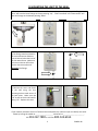
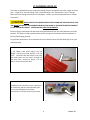
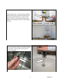
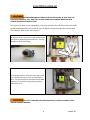
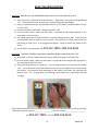
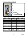
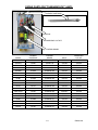
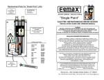
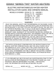
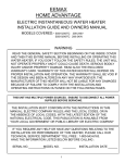
INSTALLATION GUIDE AND OWNER’S
MANUAL
“SINGLE POINT”, “FLOW CONTROLLED” and “THERMOSTATIC”
ELECTRIC INSTANTANEOUS WATER HEATERS
BEFORE ATTEMPTING ANY INSTALLATION, MODIFICATION OR SERVICE OF THIS
HEATER, MAKE SURE THE ELECTRICAL POWER IS DISCONNECTED.
Read and understand these instructions thoroughly before attempting the installation or service of this
water heater. Failure to follow these instructions can result in serious injury, death and/or property
damage. The warranty of this water heater will depend upon the proper installation according to these
instructions. Some heaters come supplied with separate faucet aerators. If supplied, the aerator must
be installed in the faucet for optimum performance. This heater must be used to heat water only and
be in a location where it is not subject to freezing temperatures. The manufacturer is not liable for any
damages resulting from improper installation or misuse.
This installation must conform to the latest requirements of the National Electrical Code and all
applicable state and local codes. This information is available through your local authorities. You must
understand these requirements before beginning this installation.
This unit is not required by UL 499 to have a Temperature and Pressure relief valve (T&P). You should
check with local codes to find out if one is required. If it is, it must be installed in the outlet hot water
pipe between the heater and the isolation valve.
IMPORTANT SAFETY INSTRUCTIONS
When using this electrical equipment, basic safety precautions should always be followed, including the
following:
READ AND FOLLOW ALL INSTRUCTIONS
A green terminal (or a wire connector marked “G”, “GR, “Ground”, or “GROUNDING”) is provided within
the control box. To reduce the risk of electric shock, connect this terminal or connector to the
grounding terminal of the electric service or supply panel with a continuous copper wire in accordance
with the Canadian Electrical Code, Part I. (Canadian Installations Only)
1
EX9001-48
Connect only to a circuit protected by a Class A ground fault circuit interrupter.
Attention: Brancher uniquement à un circuit protégé par un disjoncteur de fuite de terre de Classe A.
(Canadian Installations Only)
Do not install in a bath enclosure or shower stall or connect to a salt-regenerated
water softener or a water supply of salt water. Attention: Ne pas installer dans une baignoire ou une
cabine de douche et ne pas brancher à un adoucisseur d’eau régénéré avec du sel ou à un
approvisionnement en eau salée. (Canadian Installations Only)
Use copper conductors only. Use bonding conductor in accordance with the Canadian Electrical Code
Part I. Utilisez dez conducteurs en cuive uniquement. Utilisez des conducteurs de mize à la masse
conformement au Code Canadien de L’Électricité, Partie I. (Canadian Installations Only)
SAVE THESE INSTRUCTIONS
GENERAL
The Eemax “Single Point” or “SP”, “ Flow Controlled” or “EX” and “Thermostatic” or “EX_T” heaters will
provide optimum performance and energy savings when located under the sink and as close as possible
to the point of hot water use. The heater should be BELOW the point of use. Failure to do so may void
the warranty. Contact your Eemax representative for further information.
“Single Point” heaters take in cold water ONLY and heat it to temperatures suitable for hand washing.
“Flow Controlled” heaters take in cold water ONLY and heat it to temperatures suitable for normal
domestic usage up to a maximum of 140 degrees F.
“Thermostatic” heaters take in cold or preheated water and heat it to temperatures suitable for normal
domestic usage up to a maximum of 140 degrees F. With the “S” option, they can be used as a
temperature booster for sanitation applications like dishwashers or commercial kitchens. This is the
only heater of the three with thermostatic control.
2
EX9001-48
1) MOUNTING THE UNIT TO THE WALL
1) The heater should be mounted “under the sink” as close to the point of use as possible. “Single
Point” will have the brass fittings on the top pointing “up”. “Flow Controlled” and “Thermostatic” will
have the fittings on the bottom pointing “down”.
2) The fittings must be pointed in
the vertical direction and be at
least 16 inches below the level of
the hot water faucet. Make sure
to leave a minimum of 8 inches
service clearance at the end
OPPOSITE the fittings.
3) Remove the cover and fasten
to the wall using the four
mounting holes at each corner of
the back plate. Make sure the
“UP” arrow on the circuit board is
facing “UP”. Replace the cover.
If you need any assistance from our Technical Service Department, make sure you can identify this water
heater by having the model no:____________________ and serial no:________________________.
Call
203-267-7890 or toll free: 800-543-6163.
3
EX9001-48
2) PLUMBING HOOK-UP
The heater is supplied with brass compression fittings that are compatible with either copper or plastic
pipe. “Single Point” has 3/8” fittings. Both “Flow Controlled” and “Thermostatic” have ½” fittings.
Make sure these fittings are used for this installation. Contact your Eemax representative for further
information.
NEVER SUBSTITUTE THREADED PIPE FITTINGS USING PIPE DOPE OR TEFLON TAPE
AND NEVER SOLDER ANY PIPE CONNECTIONS WHILE ATTACHED TO THIS HEATER BECAUSE DAMAGE
TO THE HEATER WILL RESULT. DOING THIS WILL VOID THE WARRANTY.
Eemax strongly recommends that the heater be supplied directly from the main cold water line when
possible. This helps to avoid a potential water flow interruption to the heater which could lead to a
failure of the heating element.
For optimum performance, we recommend the use of isolation valves (full flow ball type) on the inlet
and outlet pipes.
1) The heater’s cold water INLET is on the
“RIGHT” and the hot water OUTLET is on the
“LEFT”. Install full flow ball valves to the inlet
and outlet pipes and run water through the
inlet pipe into a bucket to purge it of any
debris. Close the inlet ball valve.
2) Make sure the inlet filter screen is present in
the inlet fitting and the inlet and outlet pipes
are correctly aligned with the heater
connections to minimize stress on the heater.
4
EX9001-48
3) Remove the cover. Connect the pre-assembled
inlet and outlet pipes to the heater and fully open
the inlet and outlet ball valves. Check for water
leaks. If a leak is at a compression fitting, slowly
tighten the compression nut until it stops. Replace
the cover.
4) Open the hot water faucet and run the water a
minute or two until the flow is continuous and free
of air pockets. Close the faucet and install the
aerator (if supplied).
5
EX9001-48
3) ELECTRICAL HOOK-UP
BEFORE BEGINNING ANY WORK ON THIS INSTALLATION, BE SURE THAT THE
ELECTRICAL BREAKER IS “OFF” AND THAT ALL MOUNTING AND PLUMBING WORK HAS BEEN
COMPLETED PER THESE INSTRUCTIONS.
This heater must have its own independent circuit using insulated, UL listed, 3 wire cable (2 wire plus
ground) of the appropriate size suitable for up to 75 degree C and protected by the correctly rated
circuit breaker. Refer to the chart on page 7.
1) Power cable entry to the heater should be made
through one of the “knock-out” holes located on the
back plate or top/bottom ends of the unit. Use the
appropriate strain relief fitting.
2) The power leads are to be secured to the L1 and
L2 or L and N connectors on the terminal block or
relay. The ground lead is to be secured to the GND
connector on the block or the green ground wire
with the wire nut.
FAILURE TO GROUND THE SYSTEM MAY RESULT IN SERIOUS INJURY, DEATH
AND/OR PROPERTY DAMAGE.
6
EX9001-48
3) Leave the breaker in the “OFF” position. Proceed
to the next section:
COMMISSIONING THE HEATER
ELECTRICAL SPECIFICATIONS:
"SINGLE
POINT"
MODEL
SP2412
SP3012
SP3512
SP3208
SP4208
SP8208
SP35
SP48
SP55
SP65
SP75
SP95
n/a
SP3277
SP4277
SP60
SP80
SP90
SP100
"FLOW
CONTROLLED"
MODEL
EX2412
EX3012
EX3512
EX3208
EX4208
EX8208
EX35
EX48
EX55
EX65
EX75
EX95
n/a
EX3277
EX4277
EX60
EX80
EX90
EX100
"THERMOSTATIC"
MODEL
EX2412T
EX3012T
EX3512T
EX3208T
EX4208T
EX8208T
EX35T
EX48T
EX55T
EX65T
EX75T
EX95T
EX012240T
EX3277T
EX4277T
EX60T
EX80T
EX90T
EX100T
VOLTS
120
120
120
208
208
208
240*
240*
240*
240*
240*
240*
240*
277
277
277
277
277
277
kW
2.4
3.0
3.5
3.0
4.1
8.3
3.5
4.8
5.5
6.5
7.5
9.5
11.5
3.0
4.1
6.0
8.0
9.0
10.0
AMPS
20.0
25.0
29.2
14.4
19.7
40.0
14.6
20.0
22.9
27.0
32.0
40.0
48.0
10.8
14.8
22.0
29.0
33.0
36.0
WIRE
SIZE
AWG
12
10
10
14
12
8
14
12
10
10
8
8
6
14
14
10
10
8
8
* 240V units can be used on 208V with 25% reduced temperature output.
7
EX9001-48
4) COMMISSIONING THE HEATER
BEFORE SWITCHING THE ELECTRICAL BREAKER “ON”, MAKE SURE THE INLET AND
OUTLET BALL VALVES ARE FULLY OPEN AND WATER IS FLOWING THROUGH THE HOT WATER FAUCET
FOR A MINUTE OR TWO UNTIL THE FLOW IS CONTINUOUS AND FREE FROM AIR POCKETS. DO NOT
SWITCH THE BREAKER “ON” IF THERE IS A POSSIBILITY THE WATER IN THE HEATER IS FROZEN.
1) Make sure water is flowing through the faucet.
2) Switch “ON” the electric power supply at the breaker.
3) The power indicator light on the circuit board should
come “ON” after a delay of a few seconds.
4) Check the performance of the flow switch by opening
and closing the OUTLET BALL VALVE a few times. Keep
the INLET BALL VALVE fully “OPEN”. The power
indicator light should be “ON” ONLY when water is
flowing through the heater. Return the outlet valve to
the fully “OPEN” position.
For “Single Point” and “Flow Controlled” heaters, go to 5). For “Thermostatic”, go to 6).
5) “Single Point” and “Flow Controlled”.
At this point,
the water temperature may not be very hot. Using the
OUTLET BALL VALVE, slowly reduce water flow until the
desired temperature is achieved. Keep the INLET BALL
VALVE fully “OPEN”. NEVER RESTRICT THE WATER FLOW
USING THE INLET VALVE. The temperature is
proportional to the flow through the heater; the lower
the flow, the higher the temperature and vice versa. The
heater is fully installed and ready for use.
8
EX9001-48
6) “Thermostatic”. Water too cold. Using the
OUTLET BALL VALVE, slowly reduce water flow until the
desired temperature is achieved. Keep the INLET BALL
VALVE fully “OPEN”. NEVER RESTRICT THE WATER
FLOW USING THE INLET VALVE. The temperature is
proportional to the flow through the heater; the lower
the flow, the higher the temperature and vice versa.
The heater is fully installed and ready for use.
“Thermostatic”. Water too hot. Turn the
temperature adjustment screw counter-clockwise
about 1/8 of a turn and wait 15-20 seconds. If the
temperature remains too hot, repeat this step until the
desired temperature is achieved. The heater is fully
installed and ready for use.
TEMPERATURE RISE AT SPECIFIED FLOW RATE, DEGREES F:
"SINGLE
POINT"
MODEL
SP2412
SP3012
SP3512
SP3208
SP4208
SP8208
SP35
SP48
SP55
SP65
SP75
SP95
n/a
SP3277
SP4277
SP60
SP80
SP90
SP100
"FLOW
CONTROLLED"
MODEL
EX2412
EX3012
EX3512
EX3208
EX4208
EX8208
EX35
EX48
EX55
EX65
EX75
EX95
n/a
EX3277
EX4277
EX60
EX80
EX90
EX100
"THERMOSTATIC"
0.5
GPM
33
41
48
41
56
*
48
65
75
*
*
*
*
41
56
*
*
*
*
MODEL
EX2412T
EX3012T
EX3512T
EX3208T
EX4208T
EX8208T
EX35T
EX48T
EX55T
EX65T
EX75T
EX95T
EX012240T
EX3277T
EX4277T
EX60T
EX80T
EX90T
EX100T
1.0
GPM
16
20
24
20
28
57
24
32
38
44
51
65
73
21
28
41
55
61
68
1.5
GPM
11
14
16
14
19
38
16
21
25
30
34
43
52
14
19
27
36
41
46
2.0
GPM
8
10
12
10
14
28
12
16
19
22
26
32
39
10
14
20
27
31
34
2.5
GPM
6
8
9
8
11
14
9
13
15
18
20
26
31
8
11
15
22
26
27
* Not enough water flow to activate the heater.
9
EX9001-48
BASIC TROUBLESHOOTING
SYMPTOM: NO HEAT AND THE POWER INDICATOR LIGHT ON THE CIRCUITBOARD IS “OFF”.
1) Verify the heater is mounted to the wall correctly. “Single Point” has the brass fittings pointed
“UP”. “Flow Controlled” and “Thermostatic” have the fittings pointed “DOWN”.
2) Verify it is plumbed correctly. The cold water INLET is on the “RIGHT” and the hot water OUTLET
is on the “LEFT”.
3) No electrical power to the heater. Switch the breaker “ON”.
4) Incorrect power supply. Make sure the heater is connected to the voltage specified on the
rating label on the front cover.
5) Not enough water flow through the heater to turn the heating element “ON”. Check the inlet
and outlet ball valves to make sure they are open. Also check the inlet filter screen inside the
inlet fitting to make sure it is not plugged (see page 4). Clean or replace the aerator at the
faucet.
6) Still NO HEAT? Contact Eemax. Call
SYMPTOM:
203-267-7890 or 800-543-6163.
NO HEAT, LOW OR INCONSISTENT TEMPERATURE WITH INDICATOR LIGHT “ON”.
1) Water flow is too high. Reduce the water flow by slowly closing the OUTLET ball valve.
2) Incorrect power supply. Make sure the heater is connected to the voltage supply specified on
the rating label on the front cover.
3) Electrical heating element is burned out. Turn off electrical power by switching the breaker
“OFF”. Use an ohmmeter to test the resistance across the two threaded terminals at the end of
the element. The resistance varies, depending on the model of the heater, but should be less
than 30 ohms. If it is much greater or fluctuating, contact Eemax for a replacement element
cartridge.
If you need any assistance from our Technical Service Department, make sure you can identify this water
heater by having the model no:____________________ and serial number:_____________________.
Call
203-267-7890 or toll free: 800-543-6163.
10
EX9001-48
PERIODIC MAINTENANCE
This heater is designed for many years of care free use. In order to maintain consistent water flow, it
may be necessary to periodically clean the faucet aerator or the filter screen located in the brass inlet
fitting at the heater.
PART NUMBERS FOR FITTINGS, AERATORS AND AERATOR ADAPTORS
COMPRESSION FITTINGS:
3/8" NUT
3/8" SLEEVE
3/8" ADAPTOR
5/8" NUT for ½” pipe
5/8" SLEEVE for ½” pipe
AERATORS:
0.5 GPM
1.0 GPM
EX68B
EX68C
EX0068D
EX17
EX16
AERATOR ADAPTORS:
MALE 13/16"-27 X MALE 55/64"-27
FEMALE 3/4"-27 X MALE 55/64"-27
FEMALE 13/16"-24 X MALE 55/64"-27
MALE 15/16"-27 X MALE 55/64"-27
MALE 11/16"-27 X MALE 55/64"-27
MALE M24X1/FEMALE M22X1 X MALE 55/64"-27
EX0061-0.5AER
EX0061-1.0AER
EX61-339
EX61-341
EX61-349
EX61-336
EX60-344
EX61-387
If you need any assistance from our Technical Service Department, make sure you can identify this water
heater by having the model no:____________________ and serial number:_____________________.
Call
203-267-7890 or toll free: 800-543-6163.
Eemax Inc., 353 Christian Street, Oxford, CT 06478
Tel: 800-543-6163, 203-267-7890, Fax: 203-267-7975, email: [email protected]
11
EX9001-48
REPAIR PARTS FOR “SINGLE POINT” UNITS
CONTROL BOARD
EMERGENCY CUT OFF
RELAY
ELEMENT CARTRIDGE
MODEL
SP2412
SP3012
SP3512
SP3208
SP4208
SP8208
SP35
SP48
SP55
SP65
SP75
SP95
SP3277
SP4277
SP60
SP80
SP90
SP100
ELEMENT
CARTRIDGE
EX610SP
EX480SP
EX410SP
EX1440SP
EX1050SP
EX520SP
EX1650SP
EX1200SP
EX1050SP
EX890SP
EX770SP
EX630SP
EX260SP
EX1870SP
EX1280SP
EX960SP
EX850SP
EX760SP
CONTROL
BOARD
EX0183DL-30
EX0183DL-30
EX0183DL-30
EX0183DL-30
EX0183DL-30
EX0183DL-40
EX0183DL-30
EX0183DL-30
EX0183DL-30
EX0183DL-30
EX0183DL-40
EX0183DL-40
EX0183DL-30
EX0183DL-30
EX0183DL-30
EX0183DL-30
EX0183DL-40
EX0183DL-40
12
RELAY
EX250B
EX250B
EX250B
EX253B
EX253B
EX255B
EX254B
EX254B
EX254B
EX254B
EX255B
EX255B
EX251B
EX251B
EX251B
EX251B
EX253B
EX253B
EMERGENCY
CUT OFF
EX278A
EX278A
EX278A
EX278A
EX278A
EX278A
EX278A
EX278A
EX278A
EX278A
EX278A
EX278A
EX278A
EX278A
EX278A
EX278A
EX278A
EX278A
EX9001-48
REPAIR PARTS FOR “FLOW CONTROLLED” UNITS
ELEMENT CARTRIDGE
RELAY
EMERGENCY CUT OFF
CONTROL BOARD
MODEL
ELEMENT
CARTRIDGE
CONTROL
BOARD
RELAY
EMERGENCY
CUT OFF
EX2412
EX610
EX0183DL-30
EX250B
EX278A
EX3012
EX480
EX0183DL-30
EX250B
EX278A
EX3512
EX410
EX0183DL-30
EX250B
EX278A
EX3208
EX1440
EX0183DL-30
EX254B
EX278A
EX4208
EX1050
EX0183DL-30
EX254B
EX278A
EX8208
EX520
EX0183DL-40
EX255B
EX278A
EX35
EX1650
EX0183DL-30
EX254B
EX278A
EX48
EX1200
EX0183DL-30
EX254B
EX278A
EX55
EX1050
EX0183DL-30
EX254B
EX278A
EX65
EX890
EX0183DL-30
EX254B
EX278A
EX75
EX770
EX0183DL-40
EX255B
EX278A
EX95
EX630
EX0183DL-40
EX255B
EX278A
EX3277
EX260
EX0183DL-30
EX251B
EX278A
EX4277
EX1870
EX0183DL-30
EX251B
EX278A
EX60
EX1280
EX0183DL-30
EX251B
EX278A
EX80
EX960
EX0183DL-30
EX251B
EX278A
EX90
EX100
EX850
EX760
EX0183DL-40
EX0183DL-40
EX253B
EX253B
EX278A
EX278A
13
EX9001-48
REPAIR PARTS FOR “THERMOSTATIC” UNITS
ELEMENT CARTRIDGE
RELAY
EMERGENCY CUT OFF
CONTROL BOARD
MODEL
EX2412T
EX3012T
EX3512T
EX3208T
EX4208T
EX8208T
EX35T
EX48T
EX55T
EX65T
EX75T
EX95T
EX012240T
EX3277T
EX4277T
EX60T
EX80T
EX90T
EX100T
ELEMENT
CARTRIDGE
EX610
EX480
EX410
EX1440
EX1050
EX520
EX1650
EX1200
EX1050
EX890
EX770
EX630
EX500
EX260
EX1870
EX1280
EX960
EX850
EX760
CONTROL
BOARD
EX284-120
EX284-120
EX284-120
EX284AB-240
EX284AB-240
EX284AB-240
EX284AB-240
EX284AB-240
EX284AB-240
EX284AB-240
EX284AB-240
EX284AB-240
EX284AB-240
EX284AB-277
EX284AB-277
EX284AB-277
EX284AB-277
EX284AB-277
EX284AB-277
14
RELAY
EX259B
EX259B
EX259B
EX255B
EX255B
EX255B
EX255B
EX255B
EX255B
EX255B
EX255B
EX255B
EX1050-1
EX253B
EX253B
EX253B
EX253B
EX253B
EX253B
EMERGENCY
CUT OFF
EX278A
EX278A
EX278A
EX278A
EX278A
EX278A
EX278A
EX278A
EX278A
EX278A
EX278A
EX278A
EX278A
EX278A
EX278A
EX278A
EX278A
EX278A
EX278A
EX9001-48
Eemax Inc., 353 Christian Street, Oxford, CT 06478
Tel: 800-543-6163, 203-267-7890, Fax: 203-267-7975, email: [email protected]
15
EX9001-48
Eemax CE Product Plan
New Model No.
SP002120CE
SP003120CE
SP004120CE
SP004240CE
SP005240CE
SP006240CE
SP007240CE
SP008240CE
SP010240CE
SP003220CE
SP004220CE
SP006220CE
SP007220CE
SP009220CE
EX004240CE
EX005240CE
EX006240CE
EX007240CE
EX008240CE
EX010240CE
EX003220CE
EX004220CE
EX006220CE
EX007220CE
EX009220CE
EM1015
EM1024
EM1637
EM1637SP
EM2046
EM2557
EM2557SP
EM3273
EM4092
Former
Model
Number
Phase
Modules
Volts
Watts
SP2412
SP3012
SP3512
SP35
SP48
SP55
SP65
SP75
SP95
SP282*
SP332*
SP552*
SP662*
SP882*
EX35
EX48
EX55
EX65
EX75
EX95
EX282*
EX332*
EX552*
EX662*
EX882*
Same*
Same*
Same*
Same*
Same*
Same*
Same*
Same*
Same*
1
1
1
1
1
1
1
1
1
1
1
1
1
1
1
1
1
1
1
1
1
1
1
1
1
1
1
1
1
1
1
1
1
1
1
1
1
1
1
1
1
1
1
1
1
1
1
1
1
1
1
1
1
1
1
1
1
1
1
1
1
1
1
1
1
1
1
1
120
120
120
240
240
240
240
240
240
220
220
220
220
220
240
240
240
240
240
240
220
220
220
220
220
230
230
230
230
230
230
230
230
230
2.4kW
3.0kW
3.5kW
3.5kW
4.8kW
5.5kW
6.5kW
7.5kW
9.5kW
2.8kW
3.3kW
5.5kW
6.6kW
8.8kW
3.5kW
4.8kW
5.5kW
6.5kW
7.5kW
9.5kW
2.8kW
3.3kW
5.5kW
6.6kW
8.8kW
1.50kW
2.30kW
3.68kW
3.68kW
4.60kW
5.75kW
5.75kW
7.36kW
9.20kW
For repair parts, see
pages 12 and 13.
*Contact Eemax
directly.
PRESSURE
175 kPa min
1034 kPa max
16
EX9001-48