1
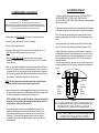
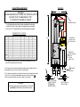
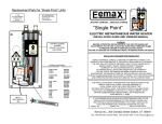
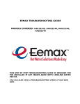
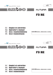
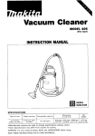
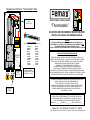
Replacement Parts for “Thermostatic” Units
®
INSTANT COMFORT…ENDLESS SAVINGS
TRIAC
PART # EX 18
“Thermostatic”
ELECTRIC INSTANTANEOUS WATER HEATER
INSTALLATION GUIDE AND OWNERS MANUAL
RELAY
ELEMENT CARTRIDGE
HEATER MODEL/ORDER REF.
TEMP
ADJ
KNOB
GROUND
WIRE
COMPRESSION
SLEEVE
PART # EX16
COMPRESSION
NUT
PART# EX17
EX2412T
EX3012T
EX3512T
EX 55T
EX 65T
EX 75T
EX 95T
EX 8208T
EX 60T
EX 80T
EX 90T
EX 100T
CONTROL BOARD
EX100/240 for 240v, 208v
EX100/277 for 277V
CARTRIDGE REF #
EX610
EX480
EX410
EX 1050
EX 890
EX 770
EX 630
EX 520
EX 1280
EX 960
EX 850
EX 760
WARNING
BEFORE ATTEMPTING INSTALLATION OF THIS UNIT OR MAKING ANY
ADJUSTMENTS TO THE UNIT, ALWAYS BE SURE CIRCUIT BREAKER IS OFF
TO PREVENT DANGER OF SERIOUS ELECTRIC SHOCK.
FAILURE TO GROUND THE SYSTEM MAY RESULT IN SERIOUS INJURY OR DEATH
INSTALLER/ CONSUMER RESPONSIBILITIES
READ THIS MANUAL CAREFULLY BEFORE ATTEMPTING TO INSTALL OR
OPERATE THIS WATER HEATER. IF THE SAFETY RULES ARE NOT FOLLOWED,
THE UNIT WILL NOT OPERATE PROPERLY AND IT COULD CAUSE DEATH,
SERIOUS BODILY INJURY AND/OR PROPERTY DAMAGE.
WARRANTY OF THIS WATERHEATER WILL DEPEND
ON PROPER INSTALLATION AND OPERATION. THE WARRANTY
WILL BE VOID IF THE DESIGN HAS BEEN ALTERED IN ANY WAY
WHATSOEVER. THE MANUFACTURER OF THIS HEATER WILL NOT BE LIABLE
FOR ANY DAMAGES BECAUSE OF FAILURE TO COMPLY WITH THE INSTALLATION
AND OPERATING INSTRUCTIONS OUTLINED ON THE FOLLOWING PAGES.
THE INSTALLATION MUST CONFORM WITH THE INSTRUCTIONS IN THIS
MANUAL AND LOCAL CODES, OR INTHE ABSENCE OF
LOCAL CODES, WITH THE LATEST EDITION OF THE
NATIONAL ELECTRICAL CODE. THIS PUBLICATION IS AVAILABLE FROM
YOUR LOCAL GOVERNMENT, ELECTRIC CO., PUBLIC LIBRARY, OR BY
WRITING UNDERWRITERS LABORATORIES, 333 PFINGSTEN RD.,
NORTHBROOK, IL. 60062
IF YOU REQUIRE HELP OR HAVE ANY QUESTIONS RELATING TO THE
INSTALLATION OR PERFORMANCE OF THIS HEATER, PLEASE CALL
OUR TECHNICAL SERVICE DEPARTMENT TOLL FREE:1-800-543-6163.
HAVE THE INFORMATION LISTED BELOW BEFORE CALLING:
MODEL NO.___________SERIAL NO.___________INSTALLATION DATE_____
Eemax Inc., 353 Christian St. Oxford, CT. 06478
TEL:1-800-543-6163, 203-267-7890, FAX: 203-267-7975, e-mail: [email protected]
GENERAL
The Eemax “Thermostatic” heater is specifically designed
to take in cold or preheated water and heat it to temperatures suitable
for the normal domestic usage up to a maximum of 1400 F. To obtain
optimum performance and energy savings, the unit should be located as
close as possible to the point of use. The unit is supplied with compression
rings and nuts suitable for direct coupling to 1/2” copper or plastic piping.
Do not use additional screwed fittings or pipe dope. Doing so will void the
warranty. DO NOT SOLDER PIPES WHILE THE UNIT IS INSTALLED
(serious damage to the electronic flow switch will result).
This heater must have its own independent circuit, using
a correctly rated breaker and
wires suitable for at least 75 oC operation.
Failure to ground this system may result in death or serious injury.
1) MOUNTING THE UNIT
1) The unit should be mounted as close to the point of use as possible.
2) This unit must only be mounted in the vertical position with the water
fittings at the bottom of the unit. Mounting other than in the vertical position
WILL cause element burn out.
3) The cold water inlet is on the right hand side and the hot water outlet is
on the left hand side. Under NO circumstances can these be reversed.
4) Leave a minimum of 8” above the unit for easy replacement of the
element.
5) The heater should be fixed to the wall using the four mounting holes at
each corner of the backplate.
NOTE: The heater should be installed below the level of all hot water
outlets serviced by this heater.
NOTE: PRESSURE RELIEF DEVICE
This unit is not required by UL to have a Pressure and Temperature
safety relief valve (PTRV). You should check with local codes to find out if
one is required in your area.
If local codes require the use of temperature and pressure relief valve it
should be installed on the outlet hot water pipe before the outlet ball valve.
TROUBLE SHOOTING
SYMPTOM: NO HEAT INDICATOR LIGHT OFF
1) ELECTRIC SUPPLY IS OFF
Turn on the main breaker.
2) Check the ECO (red re-set button) if tripped please call tech support
3) NO OR LOW WATER FLOW
Ensure that the minimum flow rate to switch on your heater is met.
“EX100T, 95T, 90T, 8208T” Models minimum flow rate = 0.75 gpm
“EX80T, 75T, 65T” Models minimum flow rate = 0.6 gpm
“EX60T, 55T” 2412T,3012T, 3512T Models
minimum flow rate = 0.5 gpm
Also check that the inlet filter screen is clear from any debris. This is
located in the brass inlet boss.
4) WATER CONNECTIONS ARE REVERSED
Cold water inlet = right side, hot water outlet = left side.
5) ELEMENT BURNED OUT
TURN OFF THE breaker!
Using an ohmmeter test the resistance of the heating element
across the two threaded termination rods on top of the element.
The resistance reading should be under 10 ohms.
If the resistance is much greater than this value, call Eemax for
a replacement element.
SYMPTOM: NO HEAT OR LOW TEMPERATURE WITH
INDICATOR LIGHT ON
1) WATER FLOW TOO HIGH
Reduce the water flow by using an outlet ball valve. See page 3
for temperature rise at various flow rates.
2) INCORRECT POWER SUPPLY
Make sure that the unit is connected to the voltage supply specified
on the rating label on the the front cover of the unit and no other.
3) ELEMENT BURNED OUT
TURN OFF THE breaker!
Repeat the steps from paragraph 4 above.
2) PLUMBING HOOK-UP
4) COMMISSIONING YOUR HEATER
1) The unit is supplied with compression fittings. USE THESE: DO NOT
USE THREADED PIPE FITTINGS. DO NOT USE PIPE DOPE
OR TEFLON TAPE ON THIS INSTALLATION. Ensure the inlet filter supplied
with this unit is in place.
IMPORTANT
Before switching “on” the power at the breaker make sure that the hot
water circuit is free of air pockets or premature failure of the heating element will occur.
To do this open all hot water faucets one at a time for a minute or two until the water flow
is continuous and free from “gulping” and from visible air pockets.
2) Take care to ensure that the pipes are correctly aligned with the inlet and
outlet bosses in order to avoid excessive stress on the heater body molding.
NOTE: Run water through the supply pipe to remove all debris from the
pipe before connecting the heater. Failure to do so could damage the flow
switch.
1) With inlet and outlet BALL VALVES fully open, turn on all hot water outlets.
2) Run for 5 minutes, turning faucet “on” and “off” repeatedly.
3) Install isolating valves (full flow ball valve type) on both inlet and outlet
pipes. This allows unit to be isolated for maintenance purposes. (Fig. 2)
3) Switch on electric supply at breaker.
4) The power indicator light should now come on with water flowing. (see Fig. 1).
NOTE: At this point water temperature may not be very hot.
5) Using the OUTLET BALL VALVE slowly reduce water flow until desired
temperature is achieved at hot water outlet. This should be 120 to 140 F without
mixing cold water.
6) Now, turn the temperature adjustment screw counter-clockwise about 1/8 of a turn,
wait for 10-15 seconds and see if the indicator light begins to pulse. If it does not,
turn another 1/8 of a turn, wait and again see if lamp begins to pulse. Repeat until
the light is pulsing regularly which indicates the temperature has stabilized at the
set temperature. Check that the temperature is what you require.
Fig 1
Inlet filter
NOTE: The water temperature is proportional to the flow through the heater.
The lower the flow the higher the temperature and vice versa.
6) Check performance of flow switch by opening and closing outlet valve a few times.
The power indicator light should be on ONLY when water is flowing through the unit.
For expected temperature rise at various rates of flow see chart.
o
NOTE: An EX95T (9.5 kW) unit at 240 V will deliver 1 gallon per minute at 65 F
temperature rise. For example, with incoming water temperature at 45oF the
unit will produce 1 gallon per minute at 110oF.
7) It is possible that drawing off cold water at comparatively high rates of flow
elsewhere in the building at the same time that the heater is working, could
cause premature element failure. Care should be taken not to starve the unit
of cold water. To prevent this from happening, open fully the main valve on
the cold supply to the building and throttle back the control valves to the other
cold water outlets.
4) When all plumbing is complete, fully check the system for water leaks
at all plumbing connections. If leak is present take corrective action. If leak
is at the compression fitting, slowly tighten compression nut until it stops.
Ensure compression fittings are tighten to 18FT.LB. Fully open both inlet
and outlet ball valves.
Run all hot water outlets fed by this heater one at a time for a minute or two
until the water flow is continuous, free from “gulping” and from all visible air
pockets.
Cold inlet
compression
fitting
DO NOT
SOLDER
Hot outlet
compression
fitting
DO NOT
SOLDER
1 1/2 “
NOTE:
ALL PLUMBING MUST BE COMPLETED BEFORE YOU
PROCEED WITH THE ELECTRICAL HOOK-UP.
TEST THE INSTALLATION FOR LEAKS BEFORE
CONNECTING THE ELECTRICAL SUPPLY.
3) ELECTRICAL HOOK-UP
FIGURE 2
4 1/4 inches
WARNING
BEFORE BEGINNING ANY WORK ON THE INSTALLATION
BE SURE THAT THE BREAKER IS “OFF”
TO AVOID ANY DANGER OF SHOCK.
MOUNTING HOLES
Your Eemax heater must have its own independent circuit using
insulated, UL listed, 3 wire cable of the appropriate size suitable
for use up to 75 oC protected by the correctly rated circuit breaker.
RATINGS OF “EX T ” UNITS
EX3012T
EX3512T
EX35T*
EX55T*
EX65T*
EX75T*
EX95T*
EX60T
EX80T
EX90T
EX100T
EX8208T
120
120
240
240
240
240
240
277
277
277
277
208
3,000 W
3,500 W
3,500 W
5,500 W
6,500 W
7,500 W
9,500 W
6,000 W
8,000 W
9,000 W
10,000 W
8,300 W
25
30
15
23
27
31
39
22
29
33
36
39
40
48
48
75
88
81
-
27
31
32
50
59
68
86
55
73
82
91
76
20
24
24
37
44
51
65
41
55
61
68
57
8 inches
RELAY
APPROPRIATE
GAUGE 3 LEAD
COPPER WIRE
TEMP
ADJ
KNOB
WIRE ENTRY
EITHER THROUGH
REAR OR
BOTTOM
KNOCK-OUTS
* The heaters are rated at 240 Volts. If the actual voltage supplied is lower
there will be a proportional drop in output.
TO
APPROPRIATE
SIZE
BREAKER
1) Wire entry into the unit should be made through the lower right hand corner of
the backplate via one of the two “knockout” holes provided.
2) The “mains” wires should be connected to the slots in the terminal block marked
L1 and L2 or N. The ground lead must be connected to the slot marked
.
Failure to ground the system may result in death or serious injury.
WARNING:
This water heater must not be switched “on” if there is
a possibility that the water in the heater is frozen.
OUTLET VALVE (B)
(ADJUST TO GIVE
APPROXIMATE
DESIRED TEMP.)
INLET VALVE (A)
(FULLY OPEN)