1
Service Bulletin
SBBI-2-181-D
Replaces SBBI-2-181-C
Repair Kit 54-4367-1
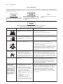
M1-G HIGH VOLUME LOW PRESSURE (HVLP)
GRAVITY FEED SPRAY GUN
GUN
ASSEMBLY
6924-0000-0
GUN
FLUID NOZZLE AIR NOZZLE
FLUID NEEDLE
INLET
MARKINGS PART NO.
MARKINGS PART NO.
MARKINGS PART NO.
18 PSI
94 (1.4mm)
45-9400
93P
46-9300
ABSS
54-4382
NOTE
TABLE OF CONTENTS
PG.SECTION
1Description
1 Installation & Assembly
2 Safety Precautions
3Operation
3 Cup Cleaning
3 Gun Cleaning & Lubrication
3 Parts Replacement
4 Parts List, Gun
5 Parts List, Cup
6Troubleshooting
7Troubleshooting
8Accessories
IMPORTANT: Before using this
equipment, read all safety precautions on page 2 and instructions.
Keep for future use.
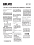
DESCRIPTION, GUN
The high volume low pressure gravity
feed M1-G guns are designed to apply a
wide variety of finishing materials.
These guns were manufactured to
provide a maximum transfer efficiency
by limiting air cap pressure to 10 psi
(complies with rules issued by SCAQMD
and other air quality authorities).
These guns will produce approximately 10 psi air cap pressure at the
recommended gun inlet pressure.
Air cap test kits are available (see
Accessories) which can be utilized to
set the exact air cap pressure.
DESCRIPTION, CUP
This cup is designed to be used with
or without the disposable cup liner.
The cup liner allows painting in any
position and simplifies clean up.
This gravity feed cup is designed to
work with the M1-G gravity feed spray
guns. The cup is constructed from
durable aluminum to provide troublefree operation. The cup fluid fitting is
electroless nickel plated brass. The
disposable cup lid is recyclable and is
constructed with recycled polyethylene. The lid has a unique drip check
to prevent paint from dripping out of
the vent in the lid.
Halogenated
Hydrocarbon
Solvents—for example: 1, 1,
1-trichloroethane and methylene chloride can react with the
aluminum in this cup and cause
an explosion hazard. Read the
data sheet for the material you
intend to spray. Do not use
spray materials containing
these solvents with this cup.
installation
NOTE
Protective coating and rust
inhibitors have been used to
keep the gun and cup in good
condition prior to shipment.
Before using, flush with solvents
so that these materials will be
removed from fluid passages.
For maximum transfer efficiency, do
not use more pressure than is necessary to atomize the material being
applied.
If an air adjusting valve is used at
the gun inlet, use Model HAV-500
or HAV-501. Some competitive
adjusting valves have significant
pressure drop that can adversely
affect spray performance. Models
HAV-500 and HAV-501 have
minimal pressure drop, which is
important for HVLP spraying.
2.Attach the gravity feed cup to the
material inlet.
assembly of cup to gun
1.Install one of the blue cup gaskets.
2.
Place this cup gasket in the fluid
inlet of the gun body.
3.Place filter in
cup outlet at
this time if
desired.
Drain Hole
Filter
4. A s s e m b l e
cup to gun
and tighten
hand tight.
Cup
Gasket
Gun Body
1.Connect the gun to a clean, moisture and oil free air supply using a
hose size of at least 5/16" I.D. hose.
Do not use 1/4" I.D. hose.
filling with paint
NOTE
INSTALLING THE LID
When gun is triggered on,
adjust regulated pressure to
desired setting to provide a
maximum of 10 psi at the air
cap. Do not use more pressure
than is necessary to atomize
the material being applied.
Excessive pressure will create
additional overspray and reduce
transfer efficiency.
Cup Fitting
Fill the cup with paint to the full mark.
DO NOT OVERFILL.
Place plastic lid on the top of the cup,
and push in the center of the lid to
assemble lid. Fold vent cap and push
onto center portion of lid (if vent cap is
not already assembled).
NOTE
If quick connects are required,
use ONLY high flow quick
connects approved for HVLP use,
such as HC-4419 and HC-4719.
Other types will not flow enough
air for proper gun operation.
Continued on Page 3
Page 2
SBBI-2-181-D
SAFETY PRECAUTIONS
This manual contains information that is important for you to know and understand. This information relates to USER SAFETY and
PREVENTING EQUIPMENT PROBLEMS. To help you recognize this information, we use the following symbols. Please pay particular
attention to these sections.
NOTE
Important safety information - A hazard
that may cause serious injury or loss of
life.
Important information that tells how to
prevent damage to equipment, or how
to avoid a situation that may cause minor injury.
Information that you should pay special
attention to.
The following hazards may occur during the normal use of this equipment.
Please read the following chart before using this equipment.
HAZARD
CAUSE
SAFEGUARDS
Fire
Solvent and coatings can be highly
flammable or combustible especially when
sprayed.
Adequate exhaust must be provided to keep air free of
accumulations of flammable vapors.
Smoking must never be allowed in the spray area.
Fire extinguishing equipment must be present in the spray area.
Solvent Spray
During use and while cleaning and flushing,
solvents can be forcefully expelled from
fluid and air passages. Some solvents can
cause eye injury.
Wear eye protection.
Inhaling Toxic Substances
Certain materials may be harmful if inhaled,
or if there is contact with the skin.
Follow the requirements of the Material Safety Data Sheet
supplied by your coating material manufacturer.
Adequate exhaust must be provided to keep the air free of
accumulations of toxic materials.
Use a mask or respirator whenever there is a chance of inhaling
sprayed materials. The mask must be compatible with the material
being sprayed and its concentration. Equipment must be as
prescribed by an industrial hygienist or safety expert, and be
NIOSH approved.
Explosion Hazard Incompatible Materials
Halogenated hydrocarbon solvents - for
example; methylene chloride and 1,1,1, Trichloroethane are not chemically
compatible with the aluminum that might be
used in many system components. The
chemical reaction caused by these solvents
reacting with aluminum can become violent
and lead to an equipment explosion.
Guns with stainless steel internal passageways may be used with
these solvents. However, aluminum is widely used in other spray
application equipment - such as material pumps, regulators,
valves, and cups. Check all equipment items before use and make
sure they can also be used safely with these solvents. Read the
label or data sheet for the material you intend to spray. If in doubt
as to whether or not a coating or cleaning material is compatible,
contact your material supplier.
General Safety
Improper operation or maintenance of
equipment.
Operators should be given adequate training in the safe use and
maintenance of the equipment (in accordance with the
requirements of NFPA-33, Chapter 15). Users must comply with all
local and national codes of practice and insurance company
requirements governing ventilation, fire precautions, operation,
maintenance, and housekeeping. These are OSHA Sections
1910.94 and 1910.107 and NFPA-33.
Cumulative Trauma
Disorders ("CTD's")
Use of hand tools may cause cumulative
trauma disorders ("CTD's").
Pain, tingling, or numbness in the shoulder, forearm, wrist, hands,
or fingers, especially during the night, may be early symptoms of a
CTD. Do not ignore them. Should you experience any such
symptoms, see a physician immediately. Other early symptoms
may include vague discomfort in the hand, loss of manual
dexterity, and nonspecific pain in the arm. Ignoring early
symptoms and continued repetitive use of the arm, wrist, and
hand can lead to serious disability. Risk is reduced by avoiding or
lessening factors 1-7.
CTD's, or musculoskeletal
disorders, involve damage
to the hands, wrists,
elbows, shoulders, neck,
and back. Carpal tunnel
syndrome and tendonitis
(such as tennis elbow or
rotator cuff syndrome) are
examples of CTD's.
CTD's, when using hand tools, tend to affect
the upper extremities. Factors which may
increase the risk of developing a CTD include:
1. High frequency of the activity.
2. Excessive force, such as gripping,
pinching, or pressing with the hands and
fingers.
3. Extreme or awkward finger, wrist, or arm
positions.
4. Excessive duration of the activity.
5. Tool vibration.
6. Repeated pressure on a body part.
7. Working in cold temperatures.
CTD's can also be caused by such activities
as sewing, golf, tennis, and bowling, to name
a few.
Page 3
Continued from Page 1
OPERATION
Turn on air supply and set gun inlet
pressure to lowest recommended
pressure for material being sprayed.
Best atomization will occur with 10
PSIG air cap pressure. However, some
materials can be sprayed at lower
pressures, improving transfer efficiency.
If the finish is too sandy and dry, the
material flow may be too low for the
atomization air pressure being used.
If the finish sags, there is too much
material flowing for the atomizing air
pressure being used.
Both of the above can be corrected by
increasing or decreasing the atomization air pressure or the material flow.
Pattern width can be altered by turning
the side port knob either clockwise to
decrease the width or counterclockwise to increase the width.
IMPORTANT: This gun may be used
with most common coating and
finishing materials. It is designed for
use with mildly corrosive and nonabrasive materials. If used with other
high corrosive or abrasive materials, it
must be expected that frequent and
thorough cleaning will be required
and the necessity for replacement of
parts will be increased.
CUP CLEANING
NOTE
For routine cleaning, it is not
necessary to remove cup from
gun. Do not remove cup gasket
from gun. If gasket is removed,
it must be replaced.
1.Remove lid and properly dispose of
any excess paint.
2.
Pour in a small amount of clean
solvent. The amount will vary with
different coatings and solvents.
3.
Reinstall lid. Hold lid with finger
covering vent hole. Shake cup to
wash down the inside surfaces.
4.Pull trigger to allow some solvent
to be flushed through gun.
5.
Remove lid and pour out dirty
solvent. Add a small amount of
clean solvent and repeat procedure.
6.
Wipe exterior of lid with a clean
cloth and clean solvent.
If a paint filter was used in the bottom
of the cup outlet, it should be removed
and cleaned or replaced at this time.
Dispose of used cup lid if contaminated and replace with new.
GUN CLEANING
To clean air nozzle and fluid nozzle,
brush exterior with a stiff bristle brush.
If it is necessary to clean air nozzle
holes, use a broom straw or toothpick
if possible. If a wire or hard instrument is used, extreme care must be
used to prevent scratching or burring
of the holes which will cause a
distorted spray pattern.
To clean fluid passages, remove
excess material from the cup, then
flush with a suitable solvent. Wipe gun
exterior with a solvent-dampened
cloth. Never completely immerse in
solvent as this is detrimental to the
lubricants and packings.
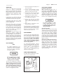
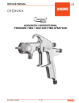
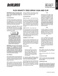
SPRAY GUN LUBRICATION
Use Binks Gunner’s Mate lube to lubricate the areas shown below.
Do not soak the lid in solvent
for extended periods of time.
Doing so could cause cup/lid
sealing problems and leakage.
The cup lid is designed to be disposable, but may be cleaned and reused if
slightly contaminated with overspray.
If lid becomes tight, or does not fit, it is
due to extended soaking in solvent. Let
lid air dry overnight and the lid should
return to its original size and fit.
A
C
A
D
E
B
A. Trigger Points
B. Needle Seal Cartridge
C. Adjusting Knobs
D. Baffle Threads
E. Spindle Assembly
SBBI-2-181-D
PARTS REPLACEMENT
Fluid Nozzle and Needle:
When replacing the fluid nozzle or
fluid needle, replace BOTH at the same
time. Using worn parts can cause fluid
leakage. Also, replace the needle seal
cartridge assembly at this time. Lightly
lubricate the threads of the fluid tip
before reassembling. Torque to 10-12
ft. lbs. Do not overtighten the fluid tip.
To prevent damage to fluid
nozzle or fluid needle, be sure
to either pull the trigger and
hold while tightening or loosening the fluid tip.
Air Valve Assembly:
Remove material control knob, spring
and fluid needle. Unscrew housing and
remove spindle assembly with springs,
seal retainers and o-rings. Lubricate
new o-rings with Gunner’s Mate.
Assemble components using material
needle. Place this assembly along with
housing into gun body and screw into
position. Remove material needle and
tighten housing.
Cartridge Assembly (Needle Packing):
Remove material valve control knob,
spring and fluid needle. Pull back
trigger and remove seal cartridge
assembly. Remove and discard plastic
shipping pin in new cartridge assembly.
Pull back trigger and insert new seal
cartridge assembly. Reassemble
needle assembly, spring and material
valve control knob.
Page 4
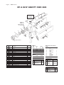
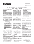
SBBI-2-181-D
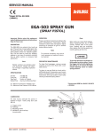
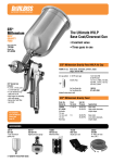
M1-G HVLP GRAVITY FEED GUN
8
10
See Page 5
for cup
information
9
23
6
14
Must be
replaced
whenever #4
is removed
13
12
5
4
2
16
11
7
12
15
3
11
17
22
21
20
18
15
19
1 (See Chart 1)
No.
Order
No.
Description
1
54-3531
Retaining Ring (For 92P and 93P Air Nozzle)
2
46-9300
Air Cap
3
See Chart 1† Fluid Nozzle
454-4368 †
Head Insert
554-4369-5▲ Head Insert Seal Ring (Kit of 5)
6●
Trigger Stud
7●
Trigger Screw
854-4364 †
Side Port Control Assembly
9▲
Retaining Ring
10 ▲O-Ring
11 ▲ ★O-Ring
12 ★
Seal Retainer
13 ▲❋
Spring, Yellow
14 54-3512 ▲
Spindle Assembly
15 ▲❋
Spring, Blue
16 54-3541†Housing
17
See Chart 2 Fluid Needle 18
54-3606
Material Valve Control Knob
19 54-768 †
Air Connection
20 54-4360
Trigger
21 54-4370▲
Seal Cartridge Assembly
22 ●
Valve Spindle Cap
23 KGP-13-K5▲ Cup Gasket (Kit of 5)
Parts
Required
1
1
1
1
1
1
1
1
1
1
2
2
1
1
2
1
1
1
1
1
1
1
1
Chart 1
Fluid
Nozzle
Order
No.
I.D. Size
In.
MM
92
45-9200
.046
1.2
93
45-9300
.052
1.3
94
45-9400
.055
1.4
97
45-9700
.070
1.8
Chart 2
Needle
Order No.
▲ NOTE: Gun Repair Kit (54-4367-1)
Contains:
Ref. No.
5
9
10
11
13
14
15
21
23
Description
Qty.
Seal
1
Retaining Ring
O-Ring
O-Ring
Spring, Yellow
Spindle
Spring, Blue
Seal Cartridge
Cup Gasket
1
1
2
1
1
2
1
1
ABSS54-4382
†Torquing Information
● Screw, Stud & Cap Kit (54-5223)
No. Description
6
7
22
Trigger Stud
Trigger Screw
Valve Spindle Cap
No. Description
Qty.
1
1
1
3
4
8
16
19
Fluid Nozzle
Head Insert
Side Port
Housing
Air Connection
Torque
10-12 Ft. Lb.
20-23 Ft. Lb.
4-6 Ft. Lb.
15-17 Ft. Lb.
15-17 Ft. Lb.
★O-Ring & Retainer Kit (54-5224)
No. Description
11 O-Ring
12 Seal Retainer
Qty.
2
2
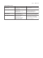
Page 5
SBBI-2-181-D
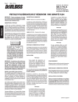
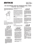
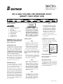
702576 900 cc aluminum CUP
1
Ref.Replacement
No. Part No.
1
2
Description
702576Metal Gravity Feed Cup*
GFC-404-K2Disposable Lid Kit (Kit of 2)
KGP-5-K5Filter Kit (Kit of 5)
*Includes one each of Ref. Nos. 1 and 2.
Full Mark
2
Page 6
SBBI-2-181-D
TROUBLESHOOTING
CONDITION
CAUSE
CORRECTION
Heavy top or
bottom pattern
Air nozzle horn holes plugged.
Obstruction on top or bottom of fluid nozzle.
Air nozzle and/or fluid nozzle seat dirty.
Clean with non-metallic point.
Clean.
Clean.
Heavy right or left
side pattern
Left or right side horn holes plugged.
Dirt on left or right side of fluid nozzle.
Clean with non-metallic point.
Clean.
Remedies for the top-heavy, bottom-heavy, right-heavy, and left-heavy patterns:
1. Determine if the obstruction is on the air nozzle or the fluid nozzle. Do this by making a test spray
pattern. Then, rotate the air nozzle one-half turn and spray another pattern. If the defect is inverted,
obstruction is on the air nozzle. Clean the air nozzle as previously instructed.
2. If the defect is not inverted, it is on the fluid nozzle. Check for a fine burr on the edge of the
fluid tip. Remove with #600 wet or dry sand paper.
3. Check for dried paint just inside the opening; remove by washing with solvent.
Heavy center pattern
Fluid flow too high for atomization air.
Material flow exceeds air nozzle's capacity.
Side port adjustment valve set too low.
Atomizing pressure too low.
Material too thick.
Side port adjusting valve set too high.
Reduce at wall or gun.
Increase fluid flow (increases gun handling
speed).
Adjust.
Jerky or fluttering spray
*Loose or damaged fluid nozzle/seat.
Material level too low.
Container tipped too far.
Obstruction in fluid passage.
Tighten or replace.
Refill.
Hold more upright.
Backflush with solvent.
Unable to get round spray
Side port adjustment screw not seating
properly.
Air nozzle retaining ring loose.
Clean or replace.
No air pressure at gun.
Material adjusting knob not open enough.
Fluid too heavy for gravity feed.
Check air supply and air lines, blow out gun air
passages.
Open material adjusting knob.
Thin material and/or change to larger tip size.
Paint bubbles in cup
Fluid nozzle not tight.
Tighten fluid nozzle to 10-12 ft-lbs.
Fluid leaking or dripping from
cup lid
Cup lid loose.
Dirty threads on cup or lid.
Cracked cup or lid.
Push in or tighten lid.
Clean.
Replace cup and lid.
Starved spray pattern
Inadequate material flow.
Low atomization air pressure.
Back material adjusting knob or change to
larger fluid nozzle size.
Increase air pressure and rebalance gun.
Excessive overspray
Too much atomization air pressure.
Gun too far from work surface.
Improper stroking (arcing, gun motion too
fast).
Reduce pressure.
Adjust to proper distance.
Move at moderate pace, parallel to work
surface.
Excessive fog
Too much or too fast-drying thinner.
Too much atomization air pressure.
Remix properly.
Reduce pressure.
Dry spray
Air pressure too high.
Gun tip too far from work surface.
Gun motion too fast.
Gun out of adjustment.
Reduce air pressure.
Adjust to proper distance.
Slow down.
Adjust.
Fluid leaking from seal cartridge
Packing worn or dry.
Replace or lubricate.
Fluid leaking or dripping from
front of gun
Dry seal cartridge.
Fluid nozzle or needle worn or damaged.
Foreign matter in fluid nozzle.
Fluid needle spring broken.
Wrong size needle or fluid nozzle.
Lubricate.
Replace fluid nozzle and needle.
Clean fluid nozzle.
Replace.
Replace.
Split spray pattern
Will not spray
*Most common problem.
Atomization air pressure too high.
Fluid flow too low.
Balance air pressure and fluid flow. Increase
spray pattern width with spreader adjustment
valve.
Thin or lower fluid flow.
Adjust.
Increase pressure.
Thin to proper consistency.
Tighten.
Page 7
SBBI-2-181-D
TROUBLESHOOTING (continued)
CONDITION
CAUSE
CORRECTION
Fluid dripping or leaking from
bottom of cup
Cup loose on gun.
Cup gasket worn or missing below cup.
Cup threads dirty.
Tighten.
Replace cup gasket.
Clean.
Runs and sags
Too much material flow.
Material too thin.
Gun tilted on an angle, or gun
motion too slow.
Adjust gun or reduce fluid flow.
Mix properly or apply light coats.
Hold gun at right angle to work and
adapt to proper gun technique.
Thin, sandy coarse finish drying
before it flows out
Gun too far from surface.
Too much air pressure.
Improper thinner being used.
Check distance. Normally approx. 8".
Reduce air pressure and check spray pattern.
Follow paint manufacturer's mixing instrs.
Thick, dimpled finish "orange peel"
Gun too close to surface.
Check distance. Normally approx. 8".
Too much material coarsely atomized.
Increase air pressure or reduce fluid flow.
Follow paint manufacturer's mixing instrs.
Air pressure too low.
Improper thinner being used.
Material not properly mixed.
Surface rough, oily, dirty.
Properly clean and prepare.
Page 8
SBBI-2-181-D
ACCESSORIES
Automotive Refinish Quick
Connects for HVLP Guns (Air)
High Flow Type
HC-4419 Stem
1/4" NPT(F)
HC-4719 Coupler
1/4" NPT(M)/NPS(M)
HC-1166 Stem
1/4" NPT(M)
HC-4720 Coupler
1/4" NPT(F)
GFC-501
(Acetal)
20 oz.
702576
(Aluminum)
900 cc
Gravity Feed
Cups
HAF-507
WhirlwindTM
In-Line Air Filter
Removes water, oil
and debris from
the air line.
192212 Professional
Spray Gun Cleaning Kit
192218 Scrubs®
Hand Cleaner Towels
HAV-500 or
HAV-501 (shown)
Adjusting Valve
HAV-500 does not
have
pressure
gauge. Use to control
air usage at gun.
192219
Gun Holder, Coated
Contains six precision tools designed
to effectively clean all DeVilbiss, Binks,
Finishline and other brand spray guns.
54-3918 Wrench
Scrubs® are a pre-moistened hand
cleaner towel for painters, body men
and mechanics that go where you go
and no water is needed.
Automotive Refinishing
Binks has authorized distributors throughout the world.
For equipment, parts and service, check the Yellow Pages
under “Automotive Body Shop Equipment and Supplies.”
For technical assistance, see listing below.
U.S./Canada Customer Service Office:
11360 S. Airfield Road, Swanton, OH 43558
Toll-Free Telephone: 1-800-445-3988 (U.S.A. and Canada only)
Toll-Free Fax: 1-800-445-6643
Gun holder made to hold
guns with gravity cups.
40-143 Large
40-128 Medium
40-141 Small
Paint Spray
Regulator
NIOSH-Certified
(TC84A-1623)
for
respiratory protection
in atmospheres not
i mm e d i a t e l y
dangerous to life.
OMX-70-K48
Paint Cup
Liner Kit
Allows quick & easy
clean-up.
Consists of:
1 Piercing Tool
48 Disposable Liners
48 Drain Bushings
Binks Worldwide Sales and Service Listing: www.
binks.com
WARRANTY
This product is covered by Binks’ 1 Year Limited Warranty.
1/12 ©2012 Binks All rights reserved. Printed in U.S.A.