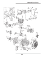
1
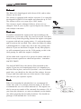
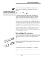
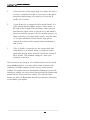
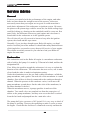
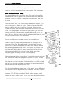
English
Radne Motor AB
Users
Manual
User
s Man
ual
Users
Manual
Intr
oduction
Introduction
We at Radne Motor congratulate you to your choice of the Raket 60 go-kart engine.
With this manual we will try to give you hints regarding the running and the maintenance of your new engine. It is our sincere hope that your new engine will give you
lots of fun and very little problems. If you follow our simple instructions in this
manual you can avoid many costly mistakes.
T he Cadet g
o-kar
lass
go-kar
o-kartt c
class
lass..
In many countries there is a Cadet class for the very youngest go-kart drivers. In
Sweden, for instance, the Cadet class is open for drivers between 8 and 10 years of
age. For this class we have prepared a special Raket 60 version which has been
homologated by the Swedish Automobile Sport Federation. In other countries it may
be different. But where the Raket 60 engine has been homologated, it is important
that you know exactly how every part of the engine must look like, because you must
not make any modifications to the standard engine. For this reason we have written
the “Product description“. The National Karting Authority that has made the homologation has normally issued an “Homologation form“, and you should read the
Homologation form and the Product description together. The homologation form
includes drawings with all important measures which can be checked during a racing
event.
In countries where Raket 60 isn’t homologated yet for a Cadet class, the engine may
be used for other purposes, e.g. for Rental karting or just for Karting-for-Fun. For
whatever purpose you own and drive your Raket 60 engine, you will find the parts
labelled “To the new owner of a Raket 60 kart engine“ and “Service advice“ valuable
reading.
Our very best advice to you if you are a beginner in the go-kart sport is to join a gokart club. In the club you will find people who can share their experience with you,
and the club may offer courses for new drivers and new mechanics. If you intend to
race, you must be member of a go-kart club, because you will need a racing license,
which only your club can issue.
Welcome to the world of karting. We at Radne Motor have been in the business for
35 years, and we have enjoyed every minute of it. We do hope that you also will find
karting to be “your cup of tea“.
!
For conversion of millimetres to inches - 1 mm corresponds to 0,03937 inches.
© Radne Motor 1997 - Revision 2 1997-04-01
2
User
s Man
ual
Users
Manual
About the R
ak
et 60 engine
Rak
aket
The Raket 60 engine is produced by Radne Motor AB in
Sweden.
It is the Radne Motor AB together with its agents who take the
responsibility for the sale and service of the Raket 60 engine and
who assist all karters who are using the engine to get the
maximum performance and fun out of it.
Pr
oduct description
Product
1. The cr
ankcase
crankcase
The crankcase must have the same shape as is shown in the
homologation form. The measures that are especially important
are those for the parts of the crankcase which surround the
crankshaft. These measures must not be changed.
4150 Crankcase
The part of the crankcase which surrounds the flywheel must
also remain unchanged (no machining allowed).
The part of the crankcase which is closest to the drive sprocket
must remain unchanged, with the exception that is acceptable to
make necessary modifications at the outside in order to be able
to fit a suitable guard over the sprocket and chain.
The oilsealing rings are “free” i.e. you can change the make as
long as the type and the size remain the same. They must be
15x26x7 mm with both a sealing lip and a dust cover lip.
The ball bearings (they normally stick on the crankshaft when
you disassemble the crankcase) are in original SKF 6202
bearings. They are “free” in respect to the make, but must be of
deep groove ball bearing type and be mounted at the same place
as the original.
4092 Vevaxel
2. T he cr
ankshaft and connecting rrod
od
crankshaft
No machining of any kind or any other modification of the
crankshaft is allowed. You must not change the balancing of the
crank shaft through machining or addition of material.
You must not machine or modify the connecting rod in any way.
3
User
s Man
ual
Users
Manual
The needle bearings at both ends of the connecting rod are
“free” in respect to the make, but must be of the same type as the
original bearings (a needle bearing in a steel cage).
3. T he c
ylinder and the spar
kplug
cylinder
sparkplug
The cylinder must remain totally unmodified i.e no machining of
any kind is allowed. For instance, deburring the edges of the
cylinder ports is regarded as machining and is therefore not
allowed.
The sparkplug is “free”. If the thread in the cylinder for the
sparkplug should be damaged, it is accepted to repair it with a
thread set of HeliCoil type or similar.
4. T he piston
It is only the original piston that you are allowed to use, without
any kind of machining or modification. The piston is always
marked with the name of the manufacturer (Radne), but other
markings on the crown of the piston may vary.
The piston rings the gudgeon pin and the clips are “free”, i.e
may be changed to similar parts of another make, as long as the
measures remain the same as for the original parts.
5. Standar
d par
ts
Standard
parts
Gaskets, nuts, bolts, screws and washers are standard parts and
as such they are “free”.
4
4087 Piston complete
User
s Man
ual
Users
Manual
6. T he carb
ur
ettor
carbur
urettor
The carburettor must be original Tillotson, series HS. No
modifications are allowed.
3048-1 Carburettor
The venturi (the most narrow part of the channel through the
carburettor) must have a diameter of maximum 17.7 mm. The
diameter of the channel closest to the carburettor manifold must
be 20.5 mm.
The following external modifications of the
carburettor are allowed:
- you may make the modifications needed for
fitting the
throttle cable, but only under the circumstance
that it has no effect on the function of the
carburettor
- you may change the gasoline inlet nipple
7. T he carb
ur
ettor manif
old
carbur
urettor
manifold
This part may under no circumstances be machined. Deburring
is regarded as machining.
8. Cylinder co
ver
cov
The cylinder cover is standard for Raket 60. It must not be
machined, more than to make it fit well to the engine. You may
also make an hole in the top for a decompression valve
9. T he ignition system
The ignition system is of a transistorised type, and is especially
developed for Raket 60. It must not be changed against any
other type or make of system. It is further forbidden to move the
ignition system from its original position.
In some countries is the ignition equipped with a rev restriction,
which cuts the ignition at 9800 revs.
Note! Apart from the fact that
it is forbidden to machine the
flywheel, it is also very
dangerous. If you machine
the outer perimeter of the
flywheel, it might explode
when you run the engine at
high revs.
10. The ffllyw
heel
ywheel
The flywheel must be original Raket 60 and marked with Radne
and the part number 5018023. The height of the flywheel fins
must be 35 mm. The only machining which is acceptable is what
may be required to balance the flywheel. The minimum weight
5
User
s Man
ual
Users
Manual
is 400 grams. The flywheel key is free. It is acceptable that you
machine it and also that you remove it completely.
11. Air filter
Must be Raket 60 original, and always fitted to the engine.
12. Exhaust system
Must be Raket 60 original.
Some countries use catalytic converter, and if so the converter
must be well functioning.
13. The c
hain spr
oc
ket
chain
sproc
ock
The chain sprocket on the drum of the centrifugal clutch must
have 11 teeth and be of type 219.
14 . Star
ter
Starter
The engine shall be equipped with standard starter. The starter
cover may not be machined, the measure and the shape shall be
according to the picture in the homologation form. Starter rope
and the starter handle can be changed to other brand, though it is
not a recommendation. Caution!! The length of the starter rope
is important for the life length of the starter spring. Standard
length is 110 cm.
15. Centrifug
al c
lutc
h
Centrifugal
clutc
lutch
All parts in the centrifugal clutch: hub, clutch, clutch drum,
clutch spring and special nut and the sirclip must be original.
The most important reason for this rule is safety. The clutch is a
safety part, and every change or modification of the clutch can
jeopardise the safety. Furthermore, in countries where the Raket
60 engine is homologated, every action taken to change the
speed at which the clutch is engaged is regarded as illegal and
hence forbidden.
6
"
Caution!
The silencer with surroundings
will be very hot. Avoid touching
when hot.
User
s Man
ual
Users
Manual
To the new owner of a Raket 60
kart engine
Please read the following two pages. It will take you perhaps 15
minutes, but it can save you a lot of aggravation and money in
the future.
When you read the following pages you will find numbers that
refer to the exploded view on page 16. Numbers in the text with
six digits are sparepart numbers engraved into the part in
question.
All four digit numbers are our own part numbers. See the
spareparts list on pages 15.
Mounting the engine on the kart
For this purpose we have developed a special engine mount for
the Raket 60 engine which makes the mounting to the frame
very simple. The part number for the engine mount is 3004.
Our engine mount will not fit karts with another spacing
between the two frame members than what is common on karts
today. If the engine mount doesn’t fit, we recommend that you
use the engine mount that belongs to your kart and that you
machine it to fit the Raket 60 engine.
When you have mounted the engine to the frame, you must link
the carburettor with the accelerator. We have made a special
throttle linkage (no 3083) which makes it easy to do this. We
recommend that you have an extra return spring that helps to
close the throttle, in order to make sure that the throttle closes
every time you release the accelerator.
Finally, you connect the fuel hose to the carburettor. Use a
transparent, flexible hose and make sure it cannot rub off. Tie it
to the chassi with plastic straps.
7
User
s Man
ual
Users
Manual
Exhaust
The Raket 60 is homologated with silenser 4140, and no other
silenser can be used.
The silencer is equipped with catalytic converter. It is especially
developped for Raket Go-kart engine and cleans the up to 70%.
The silencer will be very varm, up to 1200° inside.
You can never repair a damaged silencer, it has to be exchanged. Check if your city has a special deposit for silencers
Efficiency:
with catalytic converters.
HC
60-65%
"
NOx
Test rrun
un
CO
If you have mounted the engine on the kart according to the
description, you are now ready for your first test run. You don’t
need to worry about the gearing, because the engine is designed
to operate with only one gearing ration - 11 teeth on the engine
and 90 teeth on the rear shaft. Note, where the Raket 60 engine
is homologated for a Cadet class, this is the only gearing ratio
allowed. If you use the Raket 60 engine for any other purpose,
we still recommend you to use the 11/90 gearing, as this is the
ideal gearing for which the engine is designed.
Oil the chain with a special oil or grease for chains, and don’t
forget to mount a guard over chain and sprockets - remember
SAFETY FIRST!
You shall ALWAYS have the inlet air filter mounted on the
engine. If you race in a homologated class it is compulsory to
have the filter in place, and even if you don’t race in a homologated class, you should use the inlet air filter anyhow, because
it keeps sand, dust and water out of the interior of the engine.
This can save you expensice repairs.
Fuel.
Raket 60 is intended for unleaded fuel, we recommend 98
octane fuel, with a 3% mixture with two stroke oil. We don’t
recommend the use of so called outboard oil. The engines can
also be run on two stroke oil for extremely low mixture (1%). If
you chose this alternative, we must recommend you the utmost
care when preparing the fuel and oil mixture. You should use
packages of oil intended for 5 or 20 liters.
8
80-85%
0-20%
User
s Man
ual
Users
Manual
#
Note, don’t use so called racing oil (castor oil), because it
doesn’t mix well with petrol. If you leave the mixture in the
tank it may well separate again which can lead to engine
damage.
Hint: Do always mix you own fuel
and always use fresh and clean Ho
w to star
How
startt the engine
engine..
petrol cans.
OK, time to start the engine. Check once again that everything
is mounted according to the instructions. Close the choke
trottle, put you foot on the frame of the kart, grip the starter
handle with BOTH hands and pull the handle straight up.
NOTE, pull hard but don’t jerk. If everything is in order, the
engine will start on the first pull. As soon as the engine starts,
you must open the trottle a little. Hold down the brake and give
some trottle. Now open the choke and release the accelerator. If
everything is OK, the engine shall now idle. If the idle speed is
too high or too low you adjust the speed with the idle speed
adjustment screw. If the idle speed is correct, you will hear that
the clutch pings now and then. If the idle speed is too low, the
engine may stall for you, if it is too high the clutch will be
constantly engaged and the clutch weights and the drum will be
very hot and quickly worn out.
Basic setting of the carb
ur
etor
carbur
uretor
Identify the High and Low range needles (screws). Screw both
slowly clockwise until they bottom. Open the High range needle
(H) counter clockwise 1 turn and the Low range needle (L) 1
turn.
This is the basic setting, we guarantee that you can use this
setting when you start to practice and when you get used to the
kart and the track.
You may experiment with other settings, but here is the limit:
the H-needle must always be more than 3/4 of a turn open
The correct setting is not easy to find, but here are some good
hints:
9
User
s Man
ual
Users
Manual
1.
look at the face of the spark plug. Is it white, the fuel is
too lean - open the H needle 1/4 of a turn. Is the spark
plug black and perhaps oily, then try to close the H
needle 1/4 of a turn.
2.
if your Raket 60 is equipped with a speed limiter, it is
quite normal that the engine starts to “four stroke“ at
the end of the straight. Four stroking is when you can
hear that the engine starts to run un-even, and when it
doesn’t accelerate any more. If four stroking occurs very
often, you may try to close the H needle - note the limit
of 3/4 open minimum. If this doesn’t help, please
consult the section of this manual about maintenance
and service.
3.
if the L needle is correctly set, the engine shall start
immediately to accelerate when you open the trottle
again after having had it released. Check the setting of
the L needle. The standard setting of 1 turn open
normally is the best.
The best advice we can give you, and this advice can be worth
many hundred dollars, is to take advice from someone with
experience of Raket engines, before you try some extreme
settings. No engine has been permanently damaged by too rich
carburetor setting, but all too many have destroyed cylinder and
piston because of too lean fuel setting. Too little fuel also
means too little oil. Remember that the fuel mixture also helps
to cool down your engine.
10
User
s Man
ual
Users
Manual
Dri
ving under rrain
ain
y conditions
Driving
ainy
When driving under rainy conditions it is absolutely necessary
to protect the carburettor from water splashes and water mist. If
too much water is allowed to enter the engine, very serious
engine damages, e.g. on cylinder and piston, can occur.
11
User
s Man
ual
Users
Manual
Ser
vice Ad
vice
Service
Advice
Gener
al
General
If you are not satisfied with the performance of the engine, and other
karts are faster down the straight or out of the corners, it does not
necessarily mean that your engine are no good. It could mean that it
needs basic adjustment if the carburettor or ignition system. Of course,
the piston or the piston rings could be worn out, the radial sealing rings
could be leaking or a bearing on the crankshaft could be worn out. But
more likely, the difference between a good engine and a tired one is
found either in the carburettor or in the ignition system.
We will also tell you all you need to know to keep after the ignition
system, the clutch and the rope starter.
Normally, if you just have bought a new Raket 60 engine, you don’t
need to read this part of the manual. It should take many hundred hours
of driving before you need to worry about a full service of your engine.
These hints are mainly meant for you who have had your Raket 60
engine for some time.
Carb
ur
ettor
Carbur
urettor
The carburettor used on the Raket 60 engine is a membrane carburettor
with a built-in fuel pump. It is made by Tillotson in Ireland, and has the
designation HS.
If we follow the gasoline trough the carburettor it is easy to explain the
function of the carburettor. The carburettor has two covers, one is made
of steel and the other is made in aluminium casting.
Under the aluminium cover do you find a rubber membrane, called the
pump membrane, and a gasket. On each side of the membrane is a small
chamber. One of these is directly connected to the crankcase through a
channel. When the pressure in the crankcase varies, it will move the
pump membrane up and down. On the other side of the membrane, in
the other chamber is the fuel.
When the membrane moves, it pumps gasoline in and out of the
chamber. Two small valves are punched out from the same piece of
rubber as the pump membrane, and they now act so that fuel is sucked
from the fuel tank and pumped into the main inlet valve.
The pump shall give a pressure of 0.5 kp/cm2. It is very easy to check if
the pump is working. Unscrew the sparkplug to make it easier to rotate
the engine. Check that the fuel hose is connected correctly and that the
12
User
s Man
ual
Users
Manual
carburettor is mounted correctly on the engine. Check all gaskets,
especially the gasket between carburettor and the engine so that it’s not
leaking, or is blocking the channel. Then push down carefully the main
membrane with a small screwdriver trough the little hole in the punched
steel cover of the carburettor. This will open the fuel inlet needle valve.
Now rotate the engine, and check trough the transparent fuel hose if fuel
is flowing from the tank to the carburettor. If it doesen’t, push down the
main membrane, loosen the fuel hose at the tank end, and blow carefully
into the free end of the hose. You shall be able to blow slowly through
the hose and the carburettor. If you can’t - take away the aluminium
cover and check the small fuel filter (no 43 on the sparepart list) - It
could be blocked. After that, check the pump membrane - it can be
broken. That can be very hard to see, so if it has been used for some
time - change it. When you change the pump membrane, always change
the gaskets too. The membrane shall always be placed nearest to the
carburettor housing, otherwise the valves will not work. Then take a last
check of the channel between the crankcase and the carburettor.
Now check the pump action again. If it still doesn’t work, check the
needle valve (see below) in the carburettor, which could be stuck. The
pump pushes fuel towards the needle valve, but can’t open it.
Let us look at the other side of the carburettor. If you take off the steel
cover you will find an other membrane, a lever with a spring and a
needle valve.
The needle valve is held in closed position by the spring working
through the lever. The lever rests against the main membrane (which can
be recognised by the small rivet in the middle of the membrane). The
lower side of the main membrane and a cavity of the carburettor housing
forms a small fuel reservoir. When air is rushing through the carburettor,
the fuel under the membrane is sucked out. The fuel level under the
main membrane is now reduced. The membrane is moving downwards
and forces the lever to open the needle valve. Now more fuel comes in
from the pump side of the carburettor. The membrane moves upwards
and the lever can close the valve.
This is how the carburettor keeps a steady level of fuel.
From the chamber under the membrane the fuel goes through the H and
L needle valves to the venturi of the carburettor. The channels are so
thin that the fuel does not pass through unless it is sucked. The design
13
User
s Man
ual
Users
Manual
and location of the small holes through which the fuel can enter into the
venturi are of great importance for the characteristic of the carburettor.
No
w some ser
vice hints
Now
service
Lets start with the needle valve. First, take off the steel cover and the
main membrane with its gasket. Then loosen the little screw under the
membrane. Now it is possible to dismount the needle valve. Don’t lose
the spring.
Check the needle valve. The conical rubber end must be smooth. If you
can see impressions - change the valve. Check the bottom of the hole
that the needle is sitting in. It shall also be smooth. When you have
cleaned everything, start to assemble the needle valve with its lever and
spring. The spring and the lever must not be deformed (you shall have
some as spareparts). When you have assembled the needle valve, the
arm of the lever that is in contact with the membrane shall be at the same
level as the adjacent level of the carburettor.
How to check the correct opening pressure for the needle valve.
Connect a small air pump with a manometer to the fuel nipple of the
carburettor. Drop some fuel on the needle valve and pump up some
pressure. At 1.0 kp/cm2 the needle valve shall open - and you can see
that it bubbles around the needle valve. Now reduce the pressure down
to 0.5 kp/cm2. Check with a few more drops of fuel that the valve is
tight - no more bubble. If the valve is leaking all the time, clean
everything again and change to a new valve and spring.
If the opening and closing pressure doesn’t match the values given in the
text, you have to change the spring and lever until it is correct. Finally,
take a last check of the main membrane and the gasket, there is very
little that can go wrong with these. If the carburettor is carefully cleaned
and you have checked everything according to the instruction and the H
and L needles are OK - the carburettor works.
The only problem that can remain now is if the engine is very difficult to
start and don’t react on adjustments of the L-needle. Then there could be
dirt under the expansion washer, which is located under the main
membrane. The fuel that passes the L-Needle is also passing a small
chamber on its way to the venturi. In very rare cases this chamber can be
14
User
s Man
ual
Users
Manual
blocked. To solve this problem you have to drill a 2 mm hole in the
middle of the washer (no: 20) and pry a thin tool into the hole and bend
up the washer. Clean and check all the channels to and from the chamber
carefully and seal it with a new washer. To do this, place a new washer
in correct position and expand it with a gentle blow of a small hammer.
That is all, now you carburettor shall be working. Normally this
membrane carburettor will give you very few problems, but sometimes
you get a carburettor that doesn’t give good results. Then try borrow a
carburettor that you know works well. If the difference between the two
is big, you have to buy a new carburettor. It is very difficult to change a
bad one into a good one.
The ignition system
The Raket 60 is equipped with a transistor ignition system, which is
specially made for Raket kart engine. It is very reliable. Normally it does
not give any problems.
Adjustment if the R
ak
et 60 ignition system
Rak
aket
You shall start by adjusting the distance between the flywheel and
ignition unit. This is done with a non magnetic thickness gauge of 0.35
mm. It is important that you make the measurement when the poles of
the flywheel are right opposite to the poles of the ignition unit. Then put
the 0.35 mm gauge between the poles and tighten the screws that hold
the ignition unit.
Now check the ignition timing. Put a dial gauge clock into the sparkplug
hole. Turn the flywheel until the piston is in the top position (top dead
centre) and note the value. Then turn the flywheel backwards and
observe the dial. Stop when the dial shows 2.5-2.7 mm before top dead
centre. At this point the ignition system shall generate a spark. Look at
the picture to see the correct position of the flywheel in relation to the
ignition unit.
Between 2.5-2.7 mm before t.d.c the engine gives its best performance.
But if the ignition point isn’t correct, what to do? You have to dismount
the flywheel and adjust the flywheel key. You machine the key so you
can move the position of the flywheel to get the correct ignition point.
You probably have to try many times to get it right. Note that the key is
not necessary for keeping the flywheel on the crankshaft, it just makes it
easier to find the correct position for the flywheel. This is all you can do
to adjust the ignition system.
15
User
s Man
ual
Users
Manual
Do you find this very complicated? Don’t worry. It is very seldom that
the ignition point isn’t correct for a transistor ignition system, because
there are no parts that can wear. But now you know everything you need
to know just in case.
Maintenance of the ignition system
Very few things can happen to the ignition system. But, regularly check
the sparkplug cable at both ends, the vibrations can break the cable.
Change sparkplug frequently, and put some grease under the connection
to the coil.
T he rrope
ope star
ter
starter
ter..
Just remember one thing when you service the starter. The return spring
must never become the stop for the starter rope when it is in its most
extended position. For this reason you should use the original starter
rope, our sparepart 3138. When you assemble the starter you should also
remember to put some molybdenum grease on the starter return spring.
T he centrifug
al c
lutc
h.
centrifugal
clutc
lutch.
The centrifugal clutch comes from a power chain saw, and it is designed
for very rough operation. The only service you normally will have to
worry about is cleaning. Don’t put grease
on any part of the clutch, it will burn off anyhow, because the clutch can
be very hot during operation. But if you have disassembled the clutch
drum from the engine shaft, put some heat resistant grease on the needle
bearing.
If the teeth of the sprocket of the clutch drum have been worn, you need
to replace the complete drum - never try to change only the sprocket.!
To disassemble the clutch, first remove the circlip which holds the
clutch in position. NOTE, this circlip is made especially for the clutch,
and for safety reasons it must not be replaced with anything but an
original circlip. Take a moment to check the needle bearing when you
have disassembled the clutch drum. If the bearing is dry, or the needles
are blue or you can see pitting on the needles, replace the bearing. When
you put the bearing and the drum back on the shaft again, don’t forget
the pressure washer before you mount the circlip again.
16
4139 Starter
User
s Man
ual
Users
Manual
If you should need to replace the clutch hub or the weights, you must first
disassemble the drum, and then you unscrew the nut assembly which also is
one part of the needle bearing for the drum. NOTE, the nut has LEFT-HAND
threads. The clutch hub sits on the conical part of the crankshaft, and you will
need a three legged puller, to pull the hub off the shaft.
The circular spring that holds the clutch weights can be tricky to change. This
is how we do it. Put the spring in the groove of one of the weights and put the
weight and the spring in its position on the hub. Repeat with the next weight.
When you shall mount the third and last weight, you put it on its place on the
hub so that the groove of the weight is just over the top of the hub wing. If
you have the thumbs of a blacksmith you can press the spring over the hubwing and into the groove. But most likely you will need the help of a tool,
like the thick end of a screwdriver to press the spring in place. Most important
is that you must never damage the spring so that there are permanent
deformations. If you damage the spring it will soon break. You will also
affect the speed at which the clutch is engaged, which isn’t acceptable if you
drive in a homologated Cadet class.
Good luck with your Raket 60 engine.
If you follow our advice, then you will probably get many hour of
fun racing with your Raket 60 engine. You will find a lot of other
drivers that use the same engine in your club how you can change
experiences with. If you are a beginner, don’t hesitate to ask the
other more experienced drivers for advice, or ask you local Raket
dealer.
17
User
s Man
ual
Users
Manual
Spar
epar
Spare
partt list
Partno:
3002
3004
3005
3006
3008
3013
3014
3015
3016
3017
3018
3019
3020
3022
3023
3024
3025
3026
3027
3028
3029
3031
3032
3033
3034
3035
3036
3037
3038
3039
3040
3041
3043
3044
3045
Description
Raket 60 Cadett
Engine mount
Engine mount clamp
Bolt 10X30
Screw 8X40
Plate
Screw
Chokeaxle
Cap
Main diaphragm
Gasket
Screw
Expansion cap
Screw
Axle
Lever
Valve
Spring
Expansion cap
Sirclip
Fuel Elbow
H-Jet
Spring
Ball
Spring
L-Jet
Spring
Screw
Throttleshaft
Bushing
Spring
Plate
Screen
Screw
Pump diaphragm
Partno:
3046
3047
3048-1
3115
3129
3130
3131
3133
3134
3135
3136
3138
4049
4053
4065
4066
4076
4076-1
4085
4086
4087
4090
4091
4092
4093
4116
4118
4125
4126
4127
4132
4137
4140
4143
18
Description
Gasket
Cap
Carburettor HS-205
Oilsealing
Screw
Washer
Bushing
Starthandle
Stringdisc
Magnapull spring
Washer
Start string
Airfilter
Exhaust gasket
Flange
Inlet gasket
Ignition system
Ignition system with rev restrictor
Cylinder complete
Pistonring
Piston complete
Cylinder gasket
Small end bearing
Crankshaft
Main bearing
Flywheel
Nut
Screw 6X75
Cylinder cover
Exhaust spacer
Exhaust bend
Startcover
Silenser box type
Clutch
User
s Man
ual
Users
Manual
19
Radne Motor AB, Box 3035, 136 03 Haninge, Sweden.
Tel: +46-8-777 15 31, Fax: +46-8-745 39 39