1
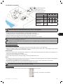
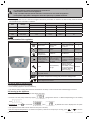
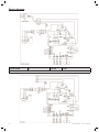
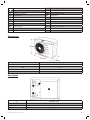
PW 5M-7M-9M-11M
Instructions for installation and use
English
More documents on:
www.zodiac-poolcare.com
H0357900.D - 2014/03
EN
• Read this notice carefully before installing, maintaining or repairing this appliance!
indicates important information that you must take into account to avoid the risk
• The symbol
of damage to persons or the appliance.
• The symbol
indicates useful information as an indication.
Warning
• As part of a continuous improvement process our products may be modified without prior notice.
• Exclusive use: the heating of pool water (must not be used for any other purpose),
• The appliance must be installed by a qualified technician, in compliance with the manufacturer’s
instructions and in compliance with current local standards. The installer is responsible for the
installation of the appliance and compliance with local regulations in matters of installation. Under
no circumstances can the manufacturer be held liable in the event that local installation standards
are not respected.
• Incorrect installation may cause damage to property or serious injuries (possibly causing death),
• It is important that this appliance be handled by skilled and apt persons (physically and mentally)
having received the instructions for use beforehand (by reading these instructions). All persons not
meeting these criteria must not approach the appliance in order to avoid exposure to dangerous
elements.
• If the appliance suffers a malfunction: do not try to repair the appliance yourself, contact your
reseller,
• Before any intervention on the appliance, make sure it has been powered off and locked out.
• Before any operations check that:
- the voltage indicated on the appliance plate corresponds to the mains voltage,
- the socket and the power supply is suitable for use with a heat pump, and that it has a ground
connection.
- the electrical plug is adapted to the socket available.
• Eliminating or shunting any safety devices automatically voids the warranty, as does the replacement
of parts using parts not originating from our warehouses,
• Keep the appliance out of the reach of children,
• Do not release R410A coolant liquid into the atmosphere. This is a fluoride greenhouse effect gas
covered by the Kyoto agreement with a global warming potential (GWP) = 1975 - (see the European
Community regulations on fluoride greenhouse effect gases Directive EC 842/2006).
• This heat pump is compatible with all types of water treatment.
1
H0357900.D - EN - 2014-03
Contents
1. Information before installing................................................................................................................... 3
1.1 General delivery terms and conditions ...................................................................................................... 3
1.2 Content............................................................................................................................................................ 3
1.3 Technical specifications ................................................................................................................................ 3
2. Installation ....................................................................................................................................................... 3
2.1 Selection of the location .............................................................................................................................. 3
2.2 Installing the appliance ................................................................................................................................ 3
2.3 Hydraulic connections .................................................................................................................................. 4
2.4 Electric connections ...................................................................................................................................... 4
3. Use....................................................................................................................................................................... 5
3.1 Presentation of the regulation .................................................................................................................... 5
3.2 Checks before commissioning ..................................................................................................................... 5
3.3 Starting up the appliance ............................................................................................................................. 5
3.4 Checks to carry out once the appliance is running .................................................................................. 6
EN
3.5 Wintering ........................................................................................................................................................ 6
4. Maintenance ................................................................................................................................................... 6
4.1 Maintenance instructions ............................................................................................................................ 6
4.2 Additional recommendations ...................................................................................................................... 6
4.3 Recycling ......................................................................................................................................................... 7
5. Troubleshooting ............................................................................................................................................ 7
5.1 Displays ........................................................................................................................................................... 7
5.2 Appliance malfunctions ................................................................................................................................ 7
5.3 FAQ ................................................................................................................................................................... 8
6. Registering the product.............................................................................................................................. 8
Are available in the appendices at the end of these instructions:
Electric Diagram
• Size
• Description
• EC Declaration of compliance
•
H0357900.D - EN - 2014-03
2
1. Information before installing
1.1 General delivery terms and conditions
All equipment, even postage and packing paid, travels at the risks and perils of the recipient. The latter must make
written reserves on the transporter’s delivery documents if damage during transport is discovered (confirmed by
registered letter to the transporter within 48 hours).
If the appliance has been tipped over, make written reserves to the transporter.
1.2 Content
PW
Wintering Cap
x1
x2
Screw-on
fitting
x2
Gasket
Ø40 Adapter
Ø50 Adapter
x2
x2
x2
1.3 Technical specifications
PW
Single phased voltage
Input power*
Rated input intensity*
5M
7M
9M
11M
2
9.09
2.6
11.82
230V-50Hz
kW
A
0.98
4.45
1.56
7.09
* with surrounding air temperature at 15°C and pool water at 24°C, humidity level 70%
• Operating temperatures: from 7 to 32°C air and up to 32°C water (30°C with Zodiac® Easy Connect)
2. Installation
Do not lift the appliance using the casing, handle it from the base.
2.1 Selection of the location
The appliance must be installed outside and be surrounded by free space (see §2.3).
•
•
the heat pump must be installed at a minimum distance from the edge of the pool in order to avoid any projections
of spray onto the appliance. This distance is determined by the electric standards applicable locally (for France: 3.5
meters).
the heat pump must not be installed:
- close to a heat source or to a source of inflammable gas,
- close to a road with a risk of water or mud being sprayed,
- facing strong winds,
- with the blower facing a permanent or temporary obstruction (window, wall, hedge, etc.) less than 3 metres away.
2.2 Installing the appliance
•
•
install on a stable, solid surface (concrete slab for example) which is level,
protect from risks of flooding due to condensates from the appliance when it is
running.
Fixing holes
The anti-vibration pads are built into the heat pump base.
The appliance can be fixed to the ground using the holes in the appliance
base, or using rails (not supplied). It is also possible to fix the appliance to
brackets (not supplied).
A drilling diagram is available on the back of the packaging box.
3
H0357900.D - EN - 2014-03
2.3 Hydraulic connections
VE: water intake valve
VB: by-pass valve
VS: water output valve
* minimum distance
PW
5M
Test pressure
bar
Service pressure bar
Load loss
mCE 1
Water flow
optimum
m³/h 4
minimum
Water flow
m³/h
maximum*
* rate not to be exceeded
7M
9M
6
1.5
1
1.5
6
8
11M
1.5
8
10
Follow the hydraulic connection direction (see § «Sizes» in the appendix).
•
•
The connection will use Ø40 piping, or Ø50 using the supplied adapter (see §1.2), use the half-union fittings to connect
to the pool filtering circuit, after the filter and before water treatment.
Installing a by-pass is mandatory and facilitates operations on the appliance.
Adjust the water flow using valve VB, and leave valves VE and VS open.
Make sure the hydraulic fittings are correctly tightened and that there are no leaks.
•
•
Condensate drainage: warning, your appliance can release several litres of water per day; it is highly recommended
to connect the drainage to the drains.
Connect an interior Ø15 pipe (not supplied) to the corrugated angle to be fitted under the appliance base
(supplied, see §1.2).
2.4 Electric connections
2.4.1 Voltage and protection
•
The appliance is designed for connection to mains electricity using a neutral TT and TNS wiring,
Electric protection: using a circuit breaker (D curve) or a fuse (Am) (calibre 16A), with a 30 mA ground fault circuit
breaker at the head of the line (circuit breaker or switch).
PW 5M-7M-9M
• connect the power cord supplied with the appliance to a 16A socket complying with the standards and regulations in
force in the country where it is installed,
• extension cords and adapters must not be used,
• If the power supply cable is not long enough, contact a qualified technician.
PW 11
• the electrical supply of the appliance must come from a protection and switching device (not supplied) complying with
the standards and regulations in force in the country,
• the electrical supply cable must not be exposed to elements that are sharp, hot or represent a crush hazard,
• check that all cables are secure and all terminal connections are correct.
•
Acceptable voltage variation: -10%, +7% (while running).
2.4.2 Connections
•
Check the strength of the power supply cable on the connection terminal block
phase (L) + neutral (N) + Ground (PE)
H0357900.D - EN - 2014-03
4
EN
•
•
•
•
•
Loose terminals can cause the terminal block to heat and lead to the warranty being voided.
It is imperative to connect the appliance to an earth rod.
Risk of electric shocks inside the appliance.
Only a qualified and experienced technician is authorised to wire inside the appliance.
If the power supply cable is damaged it should be replaced by a qualified technician.
2.4.3 Cable size
•
Power supply cable size: for a maximum length of 20 metres (calculation on the basis of: NFC 15-100), must be checked
and suitable for the installation conditions.
PW
Voltage
5M
7M
9M
11M
230V-50Hz
230V-50Hz
230V-50Hz
230V-50Hz
I Maximum absorbed
A
5.2
8.7
12.4
15.5
Cable cross section
mm²
3x1.5
3G1.5
3x1.5
3G1.5
3x2.5
3G2.5
3x2.5
3G2.5
Electric protection
A
16
16
16
20
3. Use
3.1 Presentation of the regulation
Symbol
Meaning
Fixed
Flashing
Off
/
Water flow
Water flow
correct
Water flow too low
or absent
Heating
Active
Starting up
Ambient air
temperature
Sufficient
Insufficient
Optional external
heat pump or
heating priority
connected
Option connected Option connected
not
and running to
but with no heating Option
connected
achieve heating
set
point
set point
External pump or
heating priority
Fault detected,
connected, running No fault
see §5
to reach set point
but water flow too
low or missing
Fault
Inactive
/
«On/Off» button
Pool water temperature reading and parameter setting button
Value adjustment buttons
3.2 Checks before commissioning
•
Correct tightening of hydraulic fittings,
Good stability (appliance level and vertical),
The electric power supply cable must be isolated from all sharp or hot elements that could damage or crush it.
•
•
3.3 Starting up the appliance
•
Start up water circulation and adjust the valves (see §2.3),
•
Connect the heat pump electricity supply:
then
•
(programme version n° different depending on the model)
,
Powering on: press
for 2 seconds:
then
by default the screen displays the set point
temperature,
• The appliance starts after a timer that can last up to 5 minutes,
or
to set the
• Set the required temperature (so-called «set point»): when the heat pump is running, press
temperature.
5
H0357900.D - EN - 2014-03
•
Possibility of reading the water temperature: when water is flowing through the heat pump, press
:
flashes 10 seconds then the fixed temperature set point is displayed,
Possibility of locking the keyboard:
•
- Keyboard lock: press
and
at the same time for 3 seconds:
appears for 3 seconds, then:
,
- Unlocking the keyboard: press
then:
and
at the same time for 3 seconds:
flashes for 4 seconds,
.
3.4 Checks to carry out once the appliance is running
After the heat pump commissioning steps, temporarily shut off the water flow to check that your appliance shuts down
after a few seconds (by triggering the flow meter): the water flow
indicator should flash.
3.5 Wintering
Wintering is imperative, failure to do so exposes the condenser to a risk of freezing, this situation is not
covered by the warranty. To avoid condensation damaging the appliance, do not cover it hermetically.
•
•
•
Power off the heat pump by pressing for 2 seconds and then disconnect it from the power supply,
Make sure there is no water flow in the heat pump,
Drain the water condenser (risk of freezing) by unscrewing the two pool water intake and discharge fittings behind the
heat pump,
In the event of full pool wintering: screw the two fittings back on a full turn to avoid foreign bodies from entering the
condenser,
If wintering the heat pump only: do not screw the fittings back on, instead fit 2 caps (supplied) to the condenser water
intake and discharge.
Install a micro ventilated wintering cover on the heat pump (accessory available as an option).
•
•
•
4. Maintenance
4.1 Maintenance instructions
•
•
•
•
•
•
•
•
•
It is recommended to carry out general servicing of the appliance on wintering and recommissioning, in order
to check it is in good working order and maintain its performances, as well as to prevent certain possible
defects.
These actions are the user’s responsibility and must be carried out by a technician.
Do not use high pressure cleaners.
Make sure that no foreign bodies block the ventilation grate.
Clean the evaporator (for the location see § «Size» in the appendices) using a flexible brush and a clean water hose
(disconnect the power supply), do not bend the metal heat sinks, the clean the condensate drainage pipe to remove
any dirt that may be obstructing it.
Clean the outside of the appliance, do not use solvent based products,
Check that the regulation is in working order.
Check that the condensates are draining correctly when the appliance is running.
Check that the regulation is in working order.
Check the safety devices.
Check that metal casing is connected to the earth.
Check the tightness of the electric wire connections and the cleanliness of the control box.
4.2 Additional recommendations
Relative to pressurised appliances (PED-97/23/EC)
4.2.1 Installation and maintenance
It is prohibited to install the appliance close to combustible materials or close to the air intake on an adjacent building.
For some appliances it is imperative to use the protection grate accessory if the installation is located in an unregulated
access area.
• During installation, repair, or maintenance operations it is prohibited to use piping as a step ladder: under stress the
piping could rupture and the coolant could cause serious burns.
• During maintenance of the appliance the composition and condition of the heat transporting fluid will be checked as
will the absence of traces of coolant.
• During the annual appliance seal inspection in compliance with applicable regulations, check that the high and low
pressure switches are correctly connected to the refrigeration circuit and that they cut the electric circuit when triggered.
H0357900.D - EN - 2014-03
6
•
•
EN
•
During the maintenance phase make sure there are no traces of corrosion or oil stains around the refrigerating
components.
Before any operations on the refrigerating circuit it is imperative to shut down the appliance and to wait a few minutes
before fitting temperature or pressure sensors. Some equipment such as the compressor and piping can reach
temperatures in excess of 100°C and high pressures which can cause serious burns.
•
4.2.2 Repairs
•
All welding operations are to be carried out by qualified welders
Piping can only be replaced using copper tube in compliance with NF EN 12735-1 standard.
Leak detection, pressure test:
- never use oxygen or dry air, there is a risk of fire and explosion,
- use dehydrated nitrogen or a mixture of nitrogen and the coolant indicated on the identification plate,
- the test pressure on the low and high pressure sides must not exceed 42 bar.
For the high pressure circuit piping using copper pipes of a diameter = or > than 1’’5/8, a §2.1 certificate under standard
NF EN 10204 is to be requested from the supplier and kept with the installation technical documents.
The technical information relative to the safety requirements for the different applicable directives is indicated on
the identification plate. All this information must be recorded on the appliance installation manual which must be
part of the installation technical file: model, code, serial number, maximum and minimum service voltage and service
pressure, year of manufacture, CE marking, manufacturer’s address, coolant type and weight, electric parameters,
thermodynamic and acoustic performances.
•
•
•
•
4.3 Recycling
This symbol means that your appliance must not be disposed of as household waste. It will be subject to selective
waste sorting with a view to its reuse, recycling or sale. If it contains substances that are potentially harmful to the
environment, they will be eliminated or neutralised.
Ask your reseller for information about recycling.
5. Troubleshooting
5.1 Displays
Symbol
Meaning
Cause
Sensor out of order or
incorrectly connected
Solution
Replace the sensor, contact your reseller or a
qualified technician
Sensor out of order or
incorrectly connected
Replace the sensor, contact your reseller or a
qualified technician
Low pressure
fault
Gas leak on the refrigerating
circuit
Contact your reseller or a qualified technician
High pressure
fault
•
•
Air
temperature
sensor fault
Defrosting
sensor fault
•
•
No water flow or defective
flow controller
Water temperature too high
(32°C maximum, 30°C with
Easy Connect)
Other
•
•
Check the water flow or contact your reseller or
a qualified technician
Wait for the temperature to drop
Contact your reseller or a qualified technician
Water
Sensor out of order or
Replace the sensor, contact your reseller or a
temperature
incorrectly connected
qualified technician
sensor fault
Defrosting
• Air temperature too low
• Wait for the temperature to come within the
cycle fault (>20 • The ventilator is out of order
operating range
minutes)
• The evaporator is dirty
• Contact your reseller or a qualified technician
• Air or defrosting
• Clean the evaporator (see §4.1)
temperature incorrect
• Contact your reseller or a qualified technician
5.2 Appliance malfunctions
Malfunction
The appliance is out •
of order
•
•
•
The ventilator is
running but the
compressor stops
from time to time
without any error
messages
7
•
•
Possible causes
No display
The pool temperature is above the
set point temperature
There is a message on the screen
Water flow absent or incorrect
The heat pump occasionally performs
defrosting cycles
The evaporator is dirty
•
•
•
•
•
•
Solutions
Check the power supply voltage and fuse F1
Increase the set point temperature
Check the meaning of the message in §5.1
Check the water flow (by-pass, filtering)
Normal if the outside temperature is less than 12°C
Clean the evaporator
H0357900.D - EN - 2014-03
Malfunction
The appliance is
working but the
water temperature
does not rise
•
•
•
•
•
•
•
•
Possible causes
Insufficient filtering time
Usage period not compliant
The heat pump is undersized
The automatic pool filling is blocked
in the open position
The heat insulated cover is not used
The evaporator is dirty
The appliance is incorrectly located
There is a message on the screen
•
•
•
•
•
•
•
•
•
The heat pump is
tripping the circuit
breaker
•
•
•
The circuit breaker is incorrectly or
wrongly sized
The cable size is undersized
The supply voltage is too low
•
•
•
Solutions
Switch the filtering to manual 24h/24 for the
temperature rise
Check that the outside temperature is compliant
with the operating range (see §1.3)
Check the heat pump specifications for the pool
Check that automatic filling is in working order
Position the heat insulated cover
Clean the evaporator (see §4.1)
The appliance must be installed outside.
Check that there are no obstacles at less than 4
metres from the blower, and 0.50 metres behind
the heat pump (see §2)
Check the meaning of the message §5.1
Check the circuit breaker (see § 2.4.3)
Check the cable size (see §2.4.3)
Contact your electricity supplier
5.3 FAQ
Is it possible
to improve the
temperature rise?
Why doesn’t my
heat pump heat?
My appliance is
draining water: Is
this normal?
Where should my
water treatment
system be located
relative to the
heating system?
To improve
the efficiency
of your heat
pump it is
recommended
to:
•
Cover the pool using a cover (bubble cover, shutter, etc.) to avoid heat
losses.
• Take advantage of a period when outside temperatures are warm (on
average > 10°C), to guarantee easier temperature rises (this can take several
days, its duration can vary depending on weather conditions and the heat
pump sizing).
• The hotter the surrounding air, the more the heat pump will be effective.
• Keep the evaporator clean.
Check that the • During the temperature rise phase, water circulation must be continuous
filtering time is
(24*7).
sufficient
• To maintain the temperature throughout the season, switch to «automatic»
circulation at least 12h/day (the longer this period, the more the heat pump
will have a sufficient operating range to warm).
Setting the set point to the maximum will not heat the water quicker.
• On start-up the appliance stays in «pause» for 30 seconds before starting: check that this
time has elapsed.
• When the set point temperature is reached, the heat pump stops heating: check that the
water temperature is less than the set point (see §3.3)
• When the water flow is nil or insufficient, the heat pump stops: check that the water is
flowing correctly through the heat pump and that the hydraulic fittings have been installed
correctly.
• When the outside temperature drops below 7°C, the heat pump stops: check the outside
temperature.
• The heat pump may have detected an operating fault: check for a code displayed on the
screen, if there is one refer to §5.1.
• If these points have been checked and the problem persists: contact your reseller.
• Your appliance drains water in the form of condensates. This water is the humidity from the
air that condenses when in contact with some of the cold components of the heat pump.
• Warning: your appliance can drain several litres of water per day.
• The water treatment system (chlorinator, salt water chlorinator, etc.) must be installed
preferably downstream from the heat pump (see location §2.3) and be compatible with it
(contact the manufacturer)
EN
6. Registering the product
Register your product on our website:
- be the first to be informed of new Zodiac® products and special offers,
- help us to constantly improve our product quality.
Europe & Rest of the World
www.zodiac-poolcare.com
America
www.zodiacpoolsystems.com
Australia – Pacific
www.zodiac.com.au
H0357900.D - EN - 2014-03
8
Electric diagram
PW 5M-7M-9M
P1
Power supply 230V-1N-50Hz
1
PW 11M
L-N-PE
H0357900.D - EN - 2014-03
AF
Digital display
KM2
Fan relay
Earth
KM3
Auxiliary pump relay
C1
C2
C3
CD
Compressor capacitor
Fan capacitor
Auxiliary pump capacitor
Flow rate controller
KM4
M1
M2
M3
Complementary relay
Compressor
Fan
Auxiliary pump
E1
High pressure switch
P2
Auxiliary pump connector
E2
ED1
F1
KM1
Low pressure switch
Auxiliary pump
Fuse
Compressor relay
SD1
SD2
SD3
T1
Water temperature sensor
Air temperature sensor
Defrost sensor
Transformer
Dimensions
PW
5M
7M
9M
11M
Weight (Kg)
45
47
48
51
Description
4
2
3
1
1
2
3
4
H0357900.D - EN - 2014-03
Pool water inlet
Pool water outlet
Evaporator
Auxiliary pump connector
2
Zodiac Pool Care Europe - BP 90023 - 49180 St Barthélémy d’Anjou cedex - S.A.S.U. au capital de 517 200 € / SIREN 395 068 679 / RCS PARIS
www.zodiac-poolcare.com
Pour plus de renseignements, merci de contacter votre revendeur.
For further information, please contact your retailer.
ZODIAC® is a registered trademark of Zodiac International, S.A.S.U., used under license.
Votre revendeur / your retailer