1
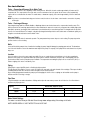
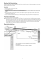
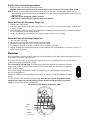
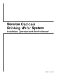
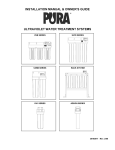
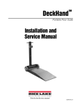
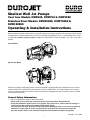
Shallow Well Jet Pumps
Cast Iron Models DSW500, DSW750 & DSW1000
Stainless Steel Models DSW500SS, DSW750SS &
DSW1000SS
Operating & Installation Instructions
Please read these instructions carefully. Failure to comply with instructions and designed operation of this system may void the warranty.
Your pump has been carefully packaged at the factory to prevent damage during shipping. However, occasional damage may occur due
to rough handling. Carefully inspect your pump for damage that could cause failure. Report any damage to your carrier or your point of
purchase.
Cast Iron Models
Stainless Steel Models
Shallow well jet pumps are single stage domestic water pumps designed for pumping potable water in applications where the water is
located less than 25 feet vertically from the pump. A pressure switch is a standard feature. The shallow well pump can be mounted to
either a precharged horizontal pressure tank or used with a precharged free standing pressure tank. The pumps can also be used with
conventional air to water tanks.
General Safety Information
1. Know the pump application, limitations and potential hazards.
- Always install a pressure relief valve to match the system pressure rating and the maximum flow rate.
- Do not pump flammable or explosive fluids such as gasoline, fuel oil, kerosene, etc. Failure to follow this warning can
result in personal injury and/or property damage and will void the warranty.
- Disconnect power and relieve all pressure from the system before attempting to install, service, relocate or perform any
maintenance. Lock the power disconnect in the open position. Tag the power disconnect to prevent unexpected
application of power. Install a screen around the inlet pipe to prevent entrapment of swimmers (if applicable).
#51451EF Rev. 10/09
1
2. Drain all liquids from the system before servicing.
3. Secure the discharge line before starting the pump. An unsecured discharge line will whip and possibly cause personal injury and/or
property damage.
4. Check hoses for weak or worn conditions before each use. Make certain all connections are secure.
5. Periodically inspect pump and system components. Perform maintenance as required.
6. Personal Safety:
a. Wear safety glasses at all times when working with pumps.
b. Keep work area clean, uncluttered and properly lighted – replace all unused tools and equipment.
c. Keep visitors at a safe distance from work area.
7. When installing pump, cover the well to prevent foreign matter from falling into well and contaminating the water and damaging
internal mechanical pumping components.
8. Always test the water from the well for purity before use. Check with local health department for test procedure.
9. Complete pump and piping system MUST be protected against freezing temperatures. Freezing temperatures could cause severe
damage and void the warranty.
10. Do not run the pump dry or damage will occur.
11. The unit should be connected to a grounded circuit equipped with a ground fault interrupter device.
12. Before installing the pump, have the electrical outlet checked by a licensed or certified electrician to make sure the outlet is properly
grounded.
13. Make sure the line voltage and frequency of electrical current supply agrees with the motor wiring.
14. Do not attempt repairs to the electric motor. All repairs to the motor must be completed at a licensed or certified electrical motor
repair shop.
Do not touch an operating motor. Modern motors are designed to operate at high temperatures.
15. Avoid kinking the electrical cord and protect from sharp objects, hot surfaces, oil and chemicals. Replace or repair damaged or worn
cords immediately.
16. Keep fingers and foreign objects away from ventilation and other openings. Do not insert any objects into the motor.
Risk of electrical shock! Never connect the green (or green and yellow) wire to a line terminal!
17. Use wire of adequate size to minimize voltage drop at the motor.
- Do not handle a pump or pump motor with wet hands, when standing on a wet or damp surface or when standing in
water. Fatal electrical shock could occur.
- Pump motor is equipped with an automatic resetting thermal overload protector and may restart unexpectedly. The
overload protector tripping is an indication of motor overloading because of operating pump at low heads (low
discharge restriction), excessively high or low voltage, inadequate wiring, incorrect motor connections.
2
Pre-installation
Tanks – Conventional Storage (Air to Water Tank)
The function of the tank is to store a quantity of water under pressure. When full, the tank contains approximately 2/3 water and 1/3
compressed air. The compressed air forces the water out of the tank when a faucet is opened. An air volume control automatically
replaces air lost or absorbed into the water. The usable water, or drawdown capacity, of the tank is approximately 1/6 of the tanks total
volume.
NOTE: If you have a conventional tank using an air volume control, the tube to the air volume control must be connected to the pump
suction pipe.
Tanks – Precharged Storage
A precharged storage tank has a flexible bladder or diaphragm that acts as a barrier between the compressed air and the water. This
barrier prevents the air from being absorbed into the water and allows the water to be acted on by compressed air at initially higher than
atmospheric pressures (precharged). More usable water is provided than with a conventional type tank. Precharged tanks are specified
in terms of a conventional tank. For example, a 20 gallon precharged tank will provide the same usable water or drawdown capacity as a
40 gallon conventional tank, but the tank is smaller in size.
Pressure Switch
The pressure switch provides for automatic operation. The pump starts when pressure drops to a cut-in setting. The pump stops when
pressure reaches a cut-out setting.
Wells
A new well should be pumped clear of sand before installing the pump. Sand will damage the pumping parts and seal. The drawdown
level of the well should not exceed the maximum rated depth for the pump. The capacity of the pump will be reduced and a loss of prime
may occur.
Location
Select a location as close to the water supply as possible. Be sure to comply with any provincial/state or local codes regarding the
placement of the pump. The equipment must be protected from the elements. A basement, frost-proof pit or heated pump house are
good locations. Make sure the pump has proper ventilation. The temperature surrounding the pump is not to exceed 100°F (40°C) or
nuisance tripping of the motor overload may occur.
Piping
Piping may be copper, rigid PVC plastic or flexible polyethylene plastic.
The pipe must be clean and free of rust or scale. Use a pipe joint compound on the male threads of the metal pipe. Teflon tape should be
used with plastic threads. All connections must be air tight to insure normal operation.
Slope all inlet piping upwards towards the pump to prevent trapping air. Unions or hose couplings can be installed near the pump to
facilitate removal for servicing or storage.
Pipe Sizes
Long horizontal pipe runs and an abundance of fittings and couplers decrease water pressure due to friction loss. See Chart below to
determine the proper pipe size.
Figure 1
Horizontal distance (feet)
Diameter
0-25
26-100
100-300
Input
1-1/4"
1-1/2"
2"
Outlet
1"
1"
1-1/4"
Motor Switch Settings
The motor is set at the factory to 230 volts. Do not change motor voltage setting if line voltage is 230 volts.
NOTE: NEVER WIRE A 115 VOLT MOTOR TO A 230 VOLT LINE.
3
Shallow Well Installation
A shallow well pump can be used when the pump is located 25 feet vertically of the water level. Shallow well pumps have only one pipe
between the pump and the water supply.
Drilled Well
1. Install a foot valve on the first section of pipe.
2. Lower the pipe into the well.
3. Add pipe until the foot valve is 5 feet below the lowest anticipated water level.
CAUTION! The foot valve should be at least 18” from the bottom of the well or sand or sediment could be drawn into the
system.
4. After the proper depth is reached, install a well seal or pitless adapter to support the pipe and prevent surface water and other
contaminants from entering the well.
5. Slope the horizontal pipe upward toward the pump to eliminate trapping air. Sloping the pipe will also aid in priming the pump.
Driven Well (or Sandpoint Well)
1. Drive the point several feet below the water table.
NOTE: A packer-type foot valve can be installed in the well. This type of foot valve allows the well to be filled with water when priming
and makes the inlet pipe much easier to test for leaks. Follow the manufacturer’s instructions when installing the packer-type foot
valve. As an alternative, an in-line check valve can be used with a driven well. The pipe between the check valve and the water
level will always be under vacuum. Leaking joints or couplings will allow air to leak into the pipe and cause abnormal pump
operation. Make sure to use pipe joint compound on all male pipe threads.
Typical Installation
Slope Piping to Well
Well
Seal
Check Valve
Vertical Lift
in Feet
Standing Water Level
Drawdown
in Feet
Pumping Water Level
Foot Valve
Some installations may require adaptation to meet individual
circumstances.
Pump may not look exactly as shown in diagram.
4
Dug Out, Cistern, Lake and Spring Installation
1. Install a foot valve on the inlet pipe and lower into the water.
CAUTION! The foot valve should be at least 18” from the bottom or sand or sediment could be drawn into the system.
NOTE: When a lake is used as a water supply, make sure the inlet pipe is deep enough to be submerged at all times. Slope the
horizontal piping upward toward the pump to prevent trapping air. The pipe must be removed during winter months or protected
against freezing.
- Protect the pipe from damage from swimmers and boats.
- Install a screen around the inlet pipe to prevent entrapment of swimmers.
Shallow Well Pump with Conventional Storage Tank
1. Install air volume control on tank.
2. Connect the copper tube from the air volume control to the tee in the suction. Be sure the connections are tight. Leaking can cause
the pump not to prime.
3. Install a valve and an isolator hose between the tank and the hose plumbing to aid in pump removal for servicing and for reducing
the noise transmitted to the house through the piping.
4. Provide a hose bib (faucet) at the lowest point in the system to drain the system for service or storage.
Shallow Well Pump with Precharged Storage Tank
1.
2.
3.
4.
5.
Shut off the power to the pump.
Open the faucet nearest the tank and allow all water to drain from the tank.
Measure the tank precharge at the valve stem using a tire pressure gauge.
If necessary, precharge with an air pump to 2 PSI below the cut in pressure of the pump.
Slope the horizontal pipes upward toward the pump to prevent trapping air. If the horizontal distance exceeds 25 ft. see Figure 1 to
determine the proper pipe size.
Electrical
We recommend that a licensed electrician be employed to do the proper wiring to pressure switch and to permanently ground the motor
in accordance to the electrical codes in your area.
Do not use an extension cord to connect your pump to the power source. From your distribution panel to the pressure switch, we
recommend a wire gauge not smaller than 14 gauge.
This is a dual voltage 115V/230V pump. The Voltage Selection Switch is located inside the terminal box. Presently the
pump is factory wired for use on 230V electrical outlets. For 115V selection, please open the terminal cover and set the
switch to the proper voltage.
Pressure switch settings (start/stop 20/40 or 30/50). This pump is factory set to 30/50. An adjustment may be done to
give other operating pressures.
Adjustment or modification of start/stop setting of pressure switch has to be done carefully. Turn adjustment nut half turn
at a time.
Turn Nut 1 clockwise to raise start and stop pressure setting. Never turn Nut 2. This will change the 20 PSI range
between start and stop pressure and may damage your tank's bladder or modify the efficiency of your water
system. Check system operation after each adjustment.
Electrical line from home to distribution panel
BLACK
RED
GREEN
GROUND
To motor lead
5
115/230V Switch
Operation
Priming the Shallow Well Pump
To prevent damage to the pump, do not start motor until pump has been filled with water.
1. Remove prime plug.
2. Fill pump and piping completely full of cold water.
3. Replace the prime plug.
4. Open a faucet to vent the system.
5. Start the motor. Water will be pumped within a few minutes. If the pump fails to prime within 5 minutes, stop the motor and refill the
pump with cold water. The priming time is proportional to the amount of air in the inlet pipe. Refill as often as necessary.
6. Let the system operate for several minutes to flush all pipes.
7. Close the faucet and allow the pump to build pressure in the tank. When the pressure reaches the cut-out setting, the motor will
stop.
The system is now in operation and will automatically cycle on demand.
Disconnect power and release all pressure from the system before attempting to install, service, relocate or perform any
maintenance. Lock the power disconnect in the open position. Tag the power disconnect to prevent unexpected application of
power.
CAUTION! Protect pump from freezing during winter conditions.
Draining the Pump
Drain openings are provided on all models. To drain the pump:
1. Remove the drain fitting and the prime plug to vent the system.
2. Drain all piping to a point below the freeze line.
Draining the Tank
Conventional tanks can be drained by opening an outlet at the lowest point in the system. Remove a plug or the air volume control to
vent the tank.
Precharged tanks force virtually all the water from the tank when the system pressure is released. No draining is necessary.
Restarting Pump
If the pump has been serviced, drained, or has not been used for some time, be sure there is water in the pump housing (volute) and the
piping to the well. There must be water in the pump housing (volute) at all times when the pump is running to avoid internal damage of
seal members (See Priming the Shallow Well).
Precharged Tank
Some air is lost through the bladder in any tank. To prevent tank failure, check the tank precharge on a yearly basis.
1. Open a faucet nearest the tank and allow all water to drain from the tank.
2. Measure the tank precharge at the valve stem using a tire gauge.
3. If necessary, adjust the precharge with an air pump to 2 PSI below the cut-in pressure of the pump.
Lubrication
The bearings used in the pumps are lifetime lubricated at the factory and require no additional lubrication.
6
Disassembly for Cleaning - Cast Iron Jet Pump Breakdown
,
Part Description
1 Pressure Gauge
2 Priming/Drain Plug,DSW500
Priming/Drain Plug,DSW750/1000
3 Pump Body,DSW500
Pump Body,DSW750/1000
4 Nozzle,DSW500
4,7 Nozzle & Venturi, DSW750
4,7 Nozzle & Venturi, DSW1000
5 Nozzle O Ring,DSW500
Nozzle O Ring,DSW750/1000
6 Venturi O Ring,DSW750/1000
Venturi O Ring,DSW500
7 Venturi,DSW500
8 Diffuser,DSW500
Diffuser,DSW750/1000
9 Impeller Nut
10 Gasket
11 Impeller,DSW500
Impeller,DSW750
Impeller,DSW1000
12 Snap Ring,DSW750/1000
Item #
302846
302849
302850
302853
302854
302839
302840
302841
302844
302845
302878
302877
302872
302812
302813
302823
302816
302820
302821
302822
302868
Part Description
13 Mechanical Seal,DSW500
Mechanical Seal,DSW750/1000
14 Pump Body O Ring,DSW500
Pump Body O Ring,DSW750/1000
15 Seal Plate,DSW500
Seal Plate,DSW750/1000
16 Motor Flange Cap Screw,DSW500
Motor Flange Cap Screw,DSW750/1000
17 Sand Slinger,DSW500
Sand Slinger,DSW750/1000
18 Pump Bracket
19 Body Cap Screw
20 Box Cover Screw
21 Junction Box Cover
22 Capacitor Junction Block
23 Stator Winding
24 Motor Capacitor,DSW500
Motor Capacitor,DSW750
Motor Capacitor,DSW1000
25 115/230V Selector
26 Motor Bearing Motor Side
27 Rotor Shaft Key
28 Rotor/Shaft
29 Motor Bearing Pump Side
7
Item #
302825
302826
302857
302858
302865
302867
302829
302830
302863
302864
302808
302824
302809
302810
302811
-
Part
30
31
32
32
33
34
35
36
37
38
39
Description
Wave Spring Washer
Motor End Bell
Fan,DSW500
Fan,DSW750/1000
Fan Cover,DSW500
Fan Cover,DSW750/1000
Motor/Pump Foot,DSW500
Motor/Pump Foot,DSW750/1000
Grounding Screw
Pressure Switch
Vent Plug
Plastic Pipe
Motor,1 HP,DSW1000
Motor,1/2 HP,DSW500
Motor,3/4 HP,DSW750
Item #
302827
302828
302814
302815
302837
302838
302847
302834
302835
302836
Disassembly for Cleaning - Stainless Steel Jet Pump Breakdown
Part
1
2
3
4
5
6
7
8
9
9
10
11
12
13
14
15
16
Description
Pump Body,DSW500SS
Pump Body,DSW750SS/1000SS
Nozzle O ring,DSW500SS
Nozzle O ring,DSW750SS/1000SS
Venturi & Nozzle,DSW500SS
Venturi & Nozzle,DSW750SS
Venturi & Nozzle,DSW1000SS
Venturi O Ring,DSW500SS
Venturi O Ring,DSW750SS/1000SS
Diffuser,DSW500SS
Diffuser,DSW750SS/1000SS
Impeller Nut
Impeller,DSW500SS
Impeller,DSW750SS
Impeller,DSW1000SS
Mechanical Seal, DSW500SS
Mechanical Seal, DSW750SS/1000SS
Pump Body O Ring,DSW500SS
Pump Body O Ring,DSW750SS/1000SS
Seal Plate,DSW500SS
Seal Plate,DSW750SS/1000SS
Sand Slinger,DSW500SS
Sand Slinger,DSW750SS/1000SS
Pump Bracket
Pump Flange Bolt
Box Cover Screw
Junction Box Cover
Capacitor,DSW500SS
Capacitor,DSW750SS
Capacitor,DSW1000SS
Item #
302851
302852
302842
302843
302869
302870
302871
302875
302876
302812
302813
302823
302817
302818
302819
302825
302826
302855
302856
302865
302866
302863
302864
302808
302824
302809
302810
302811
Part
17
18
19
20
21
22
23
24
25
26
27
28
29
30
31
32
33
34
35
36
37
-
8
Description
Capacitor Junction Box
Cord Retainer
Dual Voltage Switch
Earth Screw
Stator
Pump Foot,DSW500SS
Pump Foot,DSW750SS/1000SS
Bearing Pump Side
Shaft Key
Pressure Control
Rotor
Bearing Fan Side
Spring Washer
Motor End Cover
Motor Flange Bolt
Motor Fan,500SS
Motor Fan,750SS/1000SS
Fan Cover,DSW500SS
Fan Cover,DSW750SS/1000SS
Priming and Drain Plug
Pump Body Screws,DSW500SS
Pump Body Screws,DSW750SS/1000SS
Air Pipe Connector
Pressure Gauge
Air Pipe
Motor,1 HP,DSW1000SS
Motor,1/2 HP,DSW500SS
Motor,3/4 HP,DSW750SS
Item #
302861
302862
302827
302828
302814
302815
302848
302859
302860
302846
302831
302832
302833
Trouble Shooting Checklist
Problem
1. Motor will not run
Cause
a. Power supply failure
b. Burned out motor
2. No water supply
a. Motor not running
b. Improper priming.
c. Air leak in suction line
d. Foot valve not submerged
3. Motor overload kicks out
a. Improper wiring
b. Voltage too low
c. Inadequate ventilation
d. Pump cycling too often
4. Water supplied is
a. Nozzle or impeller clogged
below rated amount b. Well lift too high
c. Leak in piping
d. Pressure control set too
high
e. Offset piping too small
f. Failure in impeller or
diffuser vanes
Solution
a. Make sure power is turned on. Check for blown fuses, loose or broken
wires, low voltage supply, malfunctioning pressure switch.
b. Replace. Check with dealer for warranty coverage.
a. See No. 1 above.
b. Stop motor and reprime pump. Repeat until all air is removed. A leaky foot
valve could prevent proper priming in deep well pumps.
c. Check by plugging pump discharge and screw Schrader valve into tapping
on right hand side of pump. Raise pressure to about 80 lbs. with tire pump.
If pressure falls off quickly, leak is present. Inspect all connections and pipe
sections. Check with soapsuds.
d. Check vertical distance to water level in well. Replace piping with longer
length if necessary.
a. Check wiring diagram to make sure connections are properly matched to
voltage.
b. Check at pump with voltmeter. Make sure wiring is heavy enough for long
runs from power supply.
c. Take steps to increase air flow through pump location or air circulation
around motor.
d. See No. 6 below.
a. Disassemble pump and check nozzle, tube and impeller.
b. Check water level in well to see actual pumping level. Measure vertical
distance to pump and compare to tolerance for pump type.
c. See No. 2c above.
d. Compare minimum pressure on which capacity is based with operating
pressure shown on gauge.
e. Replace suction and drive lines with larger diameter pipe.
f. Inspect for wear on impeller nose or internal blockage.
5. Pressure too low to
shut off switch
a. Plugged ejector nozzle
b. Switch out of adjustment
6. Pump cycling too
often
a. Waterlogged pressure tank
b. Hidden water loss
a. Check for faulty AVC or low pressure in pre-charged tank (see Diagnosing
waterlogged tanks).
b. Check for leaky faucets and pipes drawing from tank. Also check for leaks in
foot valve bleeding water back to well.
7. Air delivered
through faucet at
low pressure
a. Air in pressure tank
b. Leak in suction line
a. Check AVC tubing for loose fittings.
b. See No. 2c above.
8. Pump is noisy
a. Suction line is plugged
a. Clear blockages from foot valve, ejector or piping.
a. Remove plug and clean out nozzle.
b. Check cut-in and cut-out pressures with accurate gauge. Switch may have
to be reset to lower pressure.
c. Well lift too high
c. See No. 4b above.
d. Offset piping too small
d. Replace suction and drive lines with larger diameter pipe.
e. Foot valve partially plugged e. Inspect foot valve screen and clear if necessary.
9
Diagnosing Waterlogged Tanks – Conventional
When a tank system has an inadequate ratio of air and water, the pump will start and stop often and erratically.
1. Disconnect the power to the pump.
2. Open the lowest faucet in the system to release all pressurized water in the system.
3. Prime the pump.
4. Reconnect the power to the pump.
NOTE: As the pump refills the tank with water, the air volume control supplies the tank with the correct air to water ratio for the system to
operate. If the air volume control is good, the pump will shut off at the desired cut-off and will be adjusted correctly.
Diagnosing Waterlogged Tanks – Precharged
If a precharged tank becomes waterlogged, the bladder is normally leaking or broken.
1. Test the tank by depressing the air valve. The air valve will expel water if the bladder is broken.
2. Replace the tank.
10
GUARANTEE
This pump is guaranteed to do the work for which it is intended when properly installed and operated. It is
warranted to be free of defects in material and workmanship for a period of two years from date of
manufacture. The only exception shall be when proof of purchase or installation is provided and then the
warranty period shall be from the date thereof.
How To Claim This Warranty
The dealer from whom you purchased your pump has a thorough knowledge of its operation and
maintenance. If trouble develops, please consult the dealer.
If a pump or part should prove defective within 24 months, return it to your dealer, transportation charges
prepaid. The repair will be made or a replacement pump or part will be supplied free of charge. The serial
number of the pump must be supplied.
This warranty does not obligate the manufacturer to bear the cost of field labor or transportation in connection
with the replacement or repair of defective parts or units, nor shall it apply to any product upon which repairs
or alterations have been made, unless authorized by the manufacturer.
The manufacturer shall in no event be liable for consequential damages or contingent liabilities arising out of
the failure of any product, its power unit or its accessories to operate properly. No express, implied or
statutory warranty other than herein set forth is made authorized to be made by the manufacturer.
WATERGROUP INC.
WATERGROUP COMPANIES INC.
FRIDLEY, MN
REGINA, SK • CAMBRIDGE, ON
1-800-354-7867
1-877-288-9888
www.watergroup.com