1
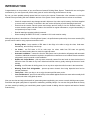
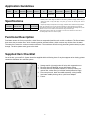
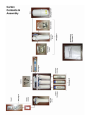
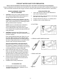
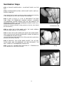
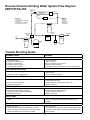
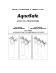
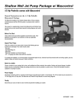
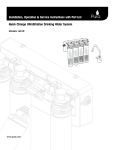
Reverse Osmosis
Drinking Water System
c/w Booster Pump and
Inlet Solenoid
Installation, Operation and Service Manual
#92364
12/10
TABLE OF CONTENTS
Introduction.............................................................................................................................................1
Product Specifications & Application Guidelines...................................................................................2
Functional Description............................................................................................................................2
Supplied Items Checklist........................................................................................................................2
Carton Contents & Assembly.................................................................................................................3
Installation Requirements.......................................................................................................................4
Installation Instructions...........................................................................................................................6
Startup Procedure................................................................................................................................12
Maintenance Schedule.........................................................................................................................13
Sanitization Procedures.......................................................................................................................14
Parts List and Drawing for EBP75TFCS-3SF......................................................................................18
Reverse Osmosis Drinking Water System Flow Diagram...................................................................19
Troubleshooting Guide.........................................................................................................................20
Reverse Osmosis Accessories............................................................................................................21
IMPORTANT WARNING - PLEASE READ
System Flushing: This reverse osmosis system contains a preservative solution to prevent microbiological
growth and freezing which if ingested may cause irritation of the gastrointestinal tract, colic, diarrhea or
other symptoms. Therefore, approximately 5 gallons of water must be drawn from the tap to flush out the
preservative solution before using the system. This volume of water represents approximately two days
of production. The water flushed should be disposed of to the drain.
Feed Water Quality: This reverse osmosis drinking water system is not intended to be used for the
treatment of water that is microbiologically unsafe or of unknown quality. If the feed water quality is
unsafe or unknown, have a sample of the water tested by a qualified laboratory or agency and implement
the necessary measures to ensure a safe water supply.
INTRODUCTION
Congratulations, on the purchase of your new Reverse Osmosis Drinking Water System. Treated with care and regular
maintenance, your new system will provide many years of service delivering purified water to the tap.
By now, you have probably already opened the box to survey the contents. Please take a few moments to review this
manual before proceeding with the installation and use of the system. Some important items to review are as follows:
•Check all components for any damage caused in shipment. Also, take a quick inventory of all items supplied
to ensure none are missing. A checklist in the next section will assist you with identifying these items.
•Ensure that the reverse osmosis system and storage tank will easily fit into the desired location. This
reverse osmosis system and tank needs to be removed for regular maintenance, so good accessibility is
an important tip to keep in mind.
•
Read all warnings contained within this manual.
•
When installing the EBP75TFCS-3SF, a standard 110V outlet must be nearby.
Although this product is described as a ‘Drinking Water System’, the purified water produced by the reverse osmosis (RO)
process can be used for many purposes around the home.
•Drinking Water - keep container of RO water in the fridge to be able to enjoy the clean, fresh taste.
Alternatively, take it directly from the tap.
•Ice Cubes - use RO water to fill ice cube trays. Ice cubes made from RO water are typically
clearer and better tasting than ice made from plain tap water.
•
Automatic Ice Makers - a water line from the RO system can be plumbed to refrigerators with automatic
icemakers. Additional accessories required to complete this connection are not included. Please consult the
refrigerator’s owner’s manual on this installation.
•Kettles and Coffee Makers - plain tap water eventually causes films and scale in these devices that is
difficult to clean. RO water is very low in dissolved minerals content, greatly reducing the chance of scale
buildup.
•
Cooking - use RO water for boiling pasta, rice or any other recipe that calls for water in the instructions.
•Washing Fresh Fruit & Vegetables - prevent tap water minerals from being deposited onto food to
maintain freshness.
•
Family Pets - Allow your dog or cat to enjoy the same purified water you do.
•
Irons and Steamers - prevent mineral buildup in household appliances that use water and eventually build
up with scale when using plain tap water.
Now you can relax and enjoy the benefits of great tasting water supplied by your reverse osmosis drinking water system.
Remember that good quality water is important to maintaining a healthy lifestyle. You can also feel good about the money
you have saved by installing your own drinking water system instead of dealing with the expense and hassle of bottled
water delivery.
1
Application Guidelines
Model
Number
Membrane
Type
Max. Feed
Water Salinity
Feed Water
Temperature
Feed Water
Pressure
Feed Water
pH
Feed Water
Supply
Feed Water
Hydrogen Sulfide
Feed Water
Manganese
Feed Water
Iron
Feed Water
Hardness
EBP75TFCS-3
TFC
2000 ppm
40-110°F
50-100 psi
2.0-11.0
Chlorinated
Unchlorinated
None
< 0.05 ppm
< 0.1 ppm
< 10 gpg
Specifications
Model
Description
Membrane
Production Rate(1)
Rejection(2)
Storage Tank
Capacity US Gal
EBP75TFCS-3
75 USGPD
up to 99%
4.0
(1)
ominal product water ratings are based on the following conditions: Supply TDS of 250 ppm
N
softened tap water, 50 psi (0.36 Mpa), 77°F (25°C), pH 8 and 15% recovery with outlet to
atmosphere.
(2)
Rejection percentages are dependent on the supply conditions and the substance being measured.
Notes: The performance of a reverse osmosis membrane is highly dependent upon pressure,
temperature and TDS. The actual volume of product water and rejection percentage will vary with
differences from the test conditions that membrane ratings are based upon.
These drinking water systems are not intended to be used for the treatment of water that is
microbiologically unsafe or of unknown quality.
Functional Description
Feed water enters the 5-micron pre-filter, which filters out suspended particles such as dirt or sediment. The filtered water
then enters the pre-carbon filter, which contains granular activated carbon, which removes any chlorine from the water.
The water then enters the reverse osmosis membrane. The membrane will allow only permeate (product water) to pass
through. The brine (waste water) goes to the drain.
Supplied Item Checklist
Out of the box, your new R.O. System should be supplied with the following items. If any items appear to be missing, please
contact the distributor who sold the system.
1. Storage tank & right angle shut-off valve with compression nut
2. Reverse Osmosis Manifold comes with Booster Pump
3.Reverse Osmosis membrane element, 5 micron pre-filter, precarbon filter, carbon filter (in individual sealed protective bags)
4.Filter sump wrench, drain line saddle assembly, tubing bundle,
feed water saddle piercing valve, quick faucet adapter
5. Faucet
Figure 1 - Supplied items
2
3
INSTALLATION REQUIREMENTS
READ THIS ENTIRE INSTALLATION AND SERVICE GUIDE BEFORE BEGINNING INSTALLATION
The Economy Reverse Osmosis Drinking Water Treatment Systems have been designed for ease of installation and
serviceability and are constructed with the finest materials available. Using these instructions will ensure a successful
installation.
All systems must be installed in accordance with applicable city, state, provincial and local plumbing codes. For installation
in Massachusetts, the Massachusetts Plumbing Code 248 CMR shall be adhered to. Consult your licensed plumber for
installation of this system. The use of saddle (piercing) valves is not permitted. To ensure a system continues to operate
at its optimum level, it is necessary to have a routine maintenance and replacement schedule (below - Maintenance
Requirements). Frequency at which filters must be changed will depend on quality of feed water supply and level of system
usage.
These RO systems contain a replaceable treatment component critical to the efficiency of the system.
Replacement of the reverse osmosis component should be with one of identical specification, as defined by WaterGroup
to assure the same efficiency. Product water shall be tested periodically to verify the system is performing properly.
All state, provincial and local government codes regarding installation of these devices must be observed.
PREPARATION
1. Check that all appropriate components are packed with your system (Figure 1).
2. Determine locations for RO component installation. Two requirements for consideration are: access to cold water supply
line and household sink drainpipe. Specific requirements are detailed below (Component Location Requirements).
COMPONENT LOCATION REQUIREMENTS
PRODUCT WATER FAUCET - Faucet may be installed in any convenient location. Make sure underside of location is
free of obstructions.
REVERSE OSMOSIS MODULE - Module may be installed under sink or in any convenient location within 15 feet of source
water supply and faucet. The 100V power outlet should be nearby to plug in the booster pump.
STORAGE TANK - Tank may be placed in any space within 15 feet of faucet, generally under kitchen sink or in an adjacent
unused cabinet. Tubing length between components should be kept to a minimum, avoiding sharp bends or kinks.
DO NOT PLACE REVERSE OSMOSIS UNIT WHERE IT WILL BE EXPOSED TO FREEZING AND/OR DIRECT
SUNLIGHT.
MODULE MUST BE EASILY REMOVABLE FOR PERFORMANCE OF ROUTINE MAINTENANCE.
Mount the unit using bracket (attached) and two screws provided in the Installation Kit.
HOLD THE MODULE BY THE FILTER HOUSINGS WHEN PICKING UP OR CARRYING UNIT.
NOTE
THIS DRINKING WATER SYSTEM IS FOR USE ON POTABLE WATER SUPPLIES ONLY. SOURCE WATER
EXCEEDING CHEMICAL PARAMETERS REQUIRES PRE-TREATMENT.
CAUTION
DO NOT USE WITH WATER THAT IS MICROBIOLOGICALLY UNSAFE OR OF UNKNOWN QUALITY WITHOUT
ADEQUATE DISINFECTION BEFORE OR AFTER THE SYSTEM.
MAINTENANCE REQUIREMENTS
Service Requirements - To insure the system operates at its optimum level, certain routine maintenance must be
performed. Frequency of maintenance performance will depend on feed water quality and level of system usage.
CLEAN: Each time filters are replaced
SANITIZE: At least once a year and each time membrane is replaced
Recommended Service Intervals - Replace filters as required or every 6 to 12 months depending on feed water quality.
Replace membrane as required based on periodic TDS rejection tests.
Maximum recommended service life for membrane is 60 months.
4
INTER-COMPONENT CONNECTIONS
Connections between cold water supplyINTER-COMPONENT
line, RO Module, storage tank,
product water faucet, and drain line are
CONNECTIONS
accomplished using plastic tubing and push-together quick-connect type fittings.
Connections between cold water supply line, RO Module, storage tank, product water faucet, and drain line are accomplished
using plastic
tubing and push-together quick-connect type fittings.
PLASTIC
TUBING
QUICK-CONNECT FITTINGS
PLASTIC
TUBINGDo not deform tube
1. Cut tube ends square
and straight.
tube square
to compress
its diameter
sodeform
it is no
1. (i.e.,
Cutcause
tube ends
and straight.
Do not
longer
round).
tube (i.e.,
cause tube to compress its diameter so it
is no longer round).
2. Make sure outer surface of tube is clear of marks or
forouter
a length
equal
twice
tube of
diameter.
2. scratches
Make sure
surface
of to
tube
is clear
marks orThis
scratches
for a
equal toagainst
twice tube
diameter.
allows
“O” ring
tolength
seat properly
tube.
This allows "O" ring to seat properly against tube.
3. Avoid sharp changes in direction when routing tubing.
3. Sharp
Avoidturns
sharp
changes
in direction
when
routing
cause
tubing
to flex and
deform,
which
tubing.
Sharp
turns
cause
tubing
to
flex
and
deform,
reduces its flow capacity and may increase
lateral
stress
which
reduces
its
flow
capacity
and
may
increase
on the fittings, causing leakage.
lateral stress on the fittings, causing leakage.
A. Push tube through Collet into Body.
Figure 2:
Fittings consist ofQUICK-CONNECT
two parts: a Body FITTINGS
and a colored collet
andFittings
symbol.consist
Colletof
color
and
symbol
corresponds
to tubing
two parts: a Body
and a colored
collet
to be
used
at that
connection
(Figure
2.A.).
and
symbol.
Collet
color and
symbol
corresponds to
tubing to be used at that connection (Figure 2.A.).
1. To install a tube, push it through Collet until it seats
firmly
atinstall
bottom
fitting
(Figure
2.A and
2.B.).
1. To
a of
tube,
push
it through
Collet
until it seats
firmly at bottom of fitting (Figure 2.A and 2.B.).
2. To remove a tube, push and hold Collet against Body
2. To
remove
a tube,
push and
hold Collet against
while
pulling
tube
out (Figure
2.C.).
Body while pulling tube out (Figure 2.C.).
B. Tube must seat firmly at bottom of
fitting.
How to Use Quick-Connect Fittings
5
C. Push Collet against Body to release
tube.
installation instructions
SADDLE-TAPPING VALVE INSTALLATION ON COPPER TUBE
CAUTION: This saddle-tapping valve is not designed for installation on flex line tubing.
NOTE: For installation in Massachusetts, the Massachusetts Plumbing Code 248 CMR shall be adhered to.
Consult your licensed plumber for installation of this system. The use of saddle (piercing) valves is not permitted.
1. CAUTION: If no shut off valve is installed under sink,
close main water valve during this Installation.
4. Connect source water feed tubing to valve body using
compression fitting.
Locate shut off valves on water lines under sink. To
identify hot supply pipe and cold supply pipe, turn
both faucets on and let water run. As water flows, hot
water pipe becomes noticeably warmer.
a. Slide nut and sleeve onto tubing (in that order).
b. Install insert into plastic tubing.
c. Install tube with insert and sleeve into valve body.
2. CAUTION: Do not install feed water assembly on hot
water line.
d. Thread compression nut onto valve body, tighten.
5. Turn saddle-tapping valve handle clockwise until it is
firmly seated and piercing lance is fully extended.
Turn off cold water supply by closing shut off valve.
Drain line by opening sink faucet. Some mixing type
faucets may require hot water supply be shut off as
well.
AUTION: Do not turn valve handle before or while
C
installing saddle-tapping valve. Make sure piercing
lance does not protrude beyond rubber gasket before
installing valve.
Assemble saddle-tapping valve assembly on tube.
a. Hold back plate against tube.
•• 3/8” copper tubing use back plate smaller radius.
•• 1/2” copper tubing, use back plate larger radius
b. Hold valve saddle against tubing in a position
directly opposite back plate.
c. Tighten screw enough so valve saddle and back
plate are held securely against tube.
d. R
otate assembly so tubing connection is aligned
toward RO Module feed port.
e. Tighten screw firmly. Do not crush tube.
CAUTION: Supply line is pierced and valve is closed.
Do not open valve until system is activated (Page 9).
Turn on cold water supply. Check saddle-tapping
valve installation for leaks. Allow water to run from
faucet for a few minutes to clear any debris in the line
caused by installation.
NOTE: All instructions refer to components shown in Figure
3 unless otherwise noted.
3. 6. OTE: If flow from sink faucet is reduced, clean
N
faucet aerator.
Figure 3 - S
addle-Tapping Valve Assembly P/N 92276
installed on 1/2” Copper Tubing
7. Trim ¼” white tube to desired length. Install ¼” white
tube into ¼” white collet as shown in Figure 1.A.
ADDITIONAL POINT OF USE CONNECTION
NOTE: Icemakers typically use 1/4” tubing as feed line. Use a reducing union (P/N 92402) for this connection.
NOTE: Reduce the 3/8” Line to 1/4” as close as possible to the additional point-of use device to minimize flow loss.
1. To connect an additional point of use (icemaker, extra
faucet in wet bar and/or another use for treated water), place a “tee” connector (P/N 92403) in 3/8” blue
line between faucet and RO Module.
2. Connect “tee” to point-of-use with 3/8” blue tubing
(P/N 87600). Connect tubing to point-of-use. Connector requirements are based on type of delivery device
i.e., a typical icemaker uses 3/8” x 1/4” reducing
device.
6
DRAIN OUTLET ASSEMBLY INSTALLATION
NOTE:State, provincial and local plumbing codes may prohibit use of saddle-tapping drain connections and may require
use of an air gap.
NOTE: Location and orientation of drain outlet assembly is vital to system performance.
Horizontal Drain Line:
Locate drain hole as close as possible to top of pipe
(between 45º and top) and as far as practical from
garbage disposal.
Vertical Drain Line:
Locate drain hole on a straight length of drainpipe next to
“P”/”S” trap between trap and sink.
Figure 4: Drain Hole Location and Installation
1. Select a location for drain hole based on type of sink and orientation of drain line.
2.Position drain outlet saddle valve on drainpipe. Allow adequate space for drilling operation.
3.Tighten saddle bolts evenly on both sides. Avoid over-tightening.
4.Using opening in drain saddle outlet as a guide, drill a 3/8” to 7/16” diameter hole in drainpipe. Clean any debris out
of drain saddle connection.
STORAGE TANK INSTALLATION
1. Hand-tighten the ball valve onto the RO storage tank. CAUTION: Do not over-tighten ball valve as this may strip
threads or compromise the “O” ring seal.
2. Slide compression nut over 3/8” white tubing.
3. a. Make sure to install the “INSERT” in the 3/8” white tubing before tightening the nut of the ball valve.
b. Push 3/8” white tubing into the ball valve as far as possible.
4. While holding the 3/8” white tubing in the ball valve, hand-tighten the compression nut onto the ball valve.
5. Connect 3/8” white tubing to the tee fitting on the RO. NOTE: With the storage tank empty, ensure the air-cell precharge is set to manufacturers instructions marked on tank. Use a hand power air pump to top up if necessary.
WARNING: Never use an air compressor to fill air cell of a reverse osmosis system storage tank. Never tamper with the
air valve located at the bottom of the tank.
Ball Valve
Tank
important
Insert
Adapter
3/8
Tubing
7
PRODUCT WATER FAUCET SITE PREPARATION
Refer to Faucet Installation Instructions (Page 6) for site location and mounting hole specifications.
Primary considerations for site selection are convenience of use and an open area under sink. An existing 7/8” Sink Hole will
also accommodate metal faucets with air-gap connections. Always check underside of selected location for obstructions.
PORCELAIN/ENAMEL OVER STEEL
OR CAST IRON SINKS
STAINLESS STEEL SINK
1. Use a center punch to make a small indentation to
mark center of desired location.
1. CAUTION: A heavy duty, variable speed drill motor
with a spring-loaded porcelain drill set (Figure 6) is
strongly recommended for this procedure.
2. Drill a pilot hole with a 1/8” metal drill bit, then enlarge
hole with a 9/16” metal drill bit.
CAUTION: The plastic sleeve supplied on pilot drill
(Figure 6.A) is to be positioned on drill bit against drill
chuck. This prevents chuck from contacting porcelain
after pilot hole has been completed.
3. Complete hole size by using a 1 1/4” chassis punch.
4. Installation hole is ready, install faucet.
A. PILOT DRILL
NOTE: Practice on discarded sinks to familiarize
yourself with operation of porcelain cutter kit.
Using carbide tipped bit with plastic sleeve (Figure
6.A.), drill pilot hole completely through porcelain and
metal underneath.
2. CAUTION: Avoid high motor R.P.M. during initial
penetration of porcelain, as high drill speed will cause
excessive chipping.
Place spring-loaded porcelain saw (Figure 6.B.) into
drill chuck. Make sure pilot guide is inserted tightly.
Insert pilot guide into pilot hole. Push down gently on
drill motor to apply light pressure to porcelain surface.
Start drill motor turning as slowly as possible.
b. SPRING LOADED PORCELAIN SAW
After initial cut has started, motor speed may be
gradually increased. The cut may require three to
four minutes to complete. Going faster could result in
excessive chipping. Be sure a complete ring has been
cut through porcelain to material underneath.
3. Place finish hole saw (Figure 6.C.) into drill chuck.
Make sure pilot guide is inserted tightly. Insert pilot
guide into pilot hole. Begin cut using a slow speed
and light pressure until porcelain (inside ring cut in
Step 2) has been penetrated to material underneath.
c FINISH HOLE SAW
4. Remove saw from hole and clean all debris from
porcelain surface. Re-insert saw into hole and cut
through remaining material.
5. Installation hole is ready, install faucet.
TILE COUNTER TOP
1. Follow procedures detailed in section labeled
“Porcelain/Enamel Over Steel” (substitute “tile” for
“Porcelain” in instructions).
Figure 6
8
PRODUCT WATER FAUCET INSTALLATION
New Faucet Installation
Refer to Faucet Site Preparation, selection on the last page.
1. Lower faucet into mounting hole and place faucet over hole.
2.Install washer, spacer, faucet washer, and nut onto faucet nipple below sink and snug them up. Be sure to properly
align faucet before tightening. Do not over tighten.
3.Install faucet connector. Apply food grade teflon tape, packaged with faucet, onto faucet nipple. Install 3/8” blue tube
into faucet connector.
4. Install 3/8” blue tube into RO module.
9
Installation of Filters
Unscrew the sumps with the help of wrench provided and install the filters as follows:
A. Sump #1 - Install Sediment Pre-filter 5 micron Cartridge
B. Sump #2 - Install Carbon Pre-filter Cartridge
C. Sump #3 - Install Carbon Post-filter Cartridge
Sump
#3
Sump
#2
Sump
#1
Installation of Membrane
Important: Keep the membrane and your hands clean in order to avoid bacterial
contamination of the membrane.
1. Disconnect the hose on the end of the membrane housing end cap from the quick
connect elbow.
2. Unscrew the end-cap.
3.Hold the membrane upside down, cut the plastic bag at the bottom, and drain off
any liquid.
4. The bottom tip of the membrane must seat firmly in the protruding female socket
inside the membrane housing.
5. Without touching the membrane, slide it into the membrane housing and discard
the plastic bag. With your thumb or the palm of your hand, push the membrane
all the way into the housing.
Important: Do not use force, and ensure that the membrane is not protruding
from the housing.
6. Replace the membrane housing end cap and hand tighten.
7. Push the tubing back into the quick connect fitting. Ensure the tubing is all the
way in.
Carbon
Post-Filter
Carbon
Pre-Filter
Sediment
Pre-Filter
RO Membrane
Housing Cap
Remove tubing
from elbow
quick connect
fitting
Figure 8A - Installing membrane without
touching
Sump #3 Sump #2 Sump #1
Figure 7 - Front View
RO Membrane
Housing
Figure 8B - Installing membrane Remove cap
10
Connecting Components
3/8”
Blue
Tubing
to
Faucet
1/4” White
Inlet Tubing
from Inlet
Saddle Valve
Sump #3
PostCarbon
Filter
Sump #1
Pre-Sediment
Filter
a. C
onnect the 1/4” white tube to the elbow of
sump #1. The other end of the elbow should be
connected to inlet saddle valve. Refer to inlet
saddle valve installation on page 6.
b. C
ut 3/8” blue tubing supplied to the desired length.
Connect the 3/8” blue tube from the (90° elbow)
granular activated carbon post-filter (Sump #3)
fitting to the quick connect fitting on the faucet
adapter. Refer to faucet installation on page 9.
1/4” Red
Tubing to
Drain Saddle
Valve
3/8”
White
Tubing
to Tank
c. C
onnect the 3/8” white tube to the center of
the male tee located on the top of the bracket.
Connect the other end of the tube to the storage
tank. Refer to the storage tank connection
installation on page 7.
Sump #3
PostCarbon
Filter
11
Flow Restrictor
RO Membrane
Housing
d. C
onnect the 1/4” red tube to the flow restrictor
and attach the other end to the drain saddle
valve. Refer to the drain saddle valve installation
on page 7.
Start-Up Procedure
WARNING: To prevent microbiological growth and freezing, this reverse osmosis system contains a preservative
solution which, if ingested, may cause irritation of the gastrointestinal tract, colic, diarrhea or other similar symptoms.
Therefore, 5 gallons (approximately two full tanks) must be drawn from the spigot to flush out the preservative. This
may represent two or three days of running, depending on conditions of the feed water.
The carbon filters require some rinsing to remove carbon fines. The filters will rinse out on their own by allowing the system
to produce 2 full tanks of water and discarding the RO product water. The following procedure may be followed if it is
desired to rinse the filters immediately before producing an RO product water.
Disconnect
tubing from
this elbow
Sump #1
Sump #2
Sump #3
Figure 9
a. Disconnect the line from the outlet side of the Pre-Carbon Filter (Sump #2). Direct tubing into a pail or catch basin.
b. Turn on the feed water by opening the needle valve on the feed water saddle valve and catch the water in the pail. The
water rinsing the filter will appear grayish until the fines are rinsed out. When the water returns to clear, close the inlet
water valve. Re-connect the white tubing back into Sump #2. The filters are now rinsed.
c. Turn on feedwater by opening the inlet water valve. Immediately check for any signs of a leak. Correct any problems if
necessary. Turn on storage tank valve.
d. It will not be uncommon to experience air bubbles or dissolved air in the product water. This will disappear after the unit
is in service for a short period of time.
e. The first two full tanks must be discarded to flush the membrane preservative out of the system as well as flush the
carbon fines from the Post Carbon Filter (Sump #3).
12
Maintenance Schedule
This schedule is designed for the average potable water supply and should be followed to ensure the proper functioning
of your drinking water system.
Pre-Filter - The pre-filter contains a 5 micron mechanical filter element. Its function is to remove suspended particles
from the feed water, thus reducing the possibility of clogging the reverse osmosis membrane. The pre-filter element
should be replaced every twelve months or earlier depending on the quality of the feed water.
Pre-Carbon Filter -The pre-filter contains a granular activated carbon. Its function is to remove chlorine from the
incoming water to prevent any damage to the TFC membrane. The Pre-Carbon filter cartridge should be replaced every
24 months.
Reverse Osmosis Module - The reverse osmosis module contains a semi-permeable membrane. Its function is
to separate water molecules from dissolved impurities in the feed water. This is accomplished by application of hydraulic
pressure greater than the osmotic pressure in water containing dissolved solids. The life of the membrane can be
determined by measuring the percentage of rejection of total dissolved solids in the water. The membrane should be
replaced every 24 to 36 months when its efficiency will decrease.
Post-Carbon Filter - The post-filter contains a granular activated carbon. Its function is to remove any taste and odor
from the water prior to delivering it to the spigot. The post-filter cartridge should be replaced every 24 months.
Activating the System
CAUTION: Make sure all water supply lines, drain lines, and fittings are secure and free from leakage.
1. Open source water supply valve. Close product water faucet. Check for leakage.
2. Turn tank valve one-quarter turn counter- clockwise to open valve (handle should be in line with tubing as it enters
connection).
3. Confirm system is producing water. Module will be sending rinse water to drain.
4. Open product water faucet and let water flow until all air has been expelled from system.
5. Close product water faucet. In 30 minutes, check connections for leaks and correct if necessary.
Icemaker/Extra point of use: Check connections on these supply lines for leaks.
6. Allow storage tank to fill overnight.
7. WARNING: DO NOT USE THE FIRST FULL STORAGE TANK OF WATER
Discard (to drain) first full tank of water by opening product water (and extra point-of-use) faucet until water flow
stops, then close faucet. This will flush sanitizing solution from system.
Icemaker: Let tray/bin fill with ice cubes. Discard all ice cubes. This flushes sanitizing solution from lines to icemaker.
8. Check the TDS reduction using a TDS Meter.
9. System is ready to use. Should there be any aftertaste or odor to water or ice cubes, repeat Steps 6 and 7.
DO NOT USE THE FIRST STORAGE TANK OF WATER
Allow storage tank to fill overnight. Dispense this water to drain. This process removes factory-installed
sanitizing solution from the entire system and sends it to drain. This process also sanitizes fittings and tubing
used during installation.
Changing Filters
Important: This RO System contains filters, which must be replaced at regular
intervals to maintain proper performance. See Maintenance Schedule for the
recommended interval for changing the filters. Local conditions may dictate more
frequent cartridge replacement. Use a drip pan to catch any water that may spill
when the housings are removed. Use only factory approved filters.
1. Close the saddle valve and open the faucet by lifting the handle. Allow
storage tank to empty.
2. Loosen and remove the appropriate filter housing(s). Discard the cartridge(s).
3. Wash the inside of the housings using a mild detergent and a soft cloth.
Do not use abrasive cleaners or pads. Thoroughly rinse all soap from the
housing before re-assembly.
13
Figure 11 - Using
sump wrench to
change filter cartridges
Sanitization Procedures for your Reverse Osmosis System
Sanitization is a simple but important part of a regular maintenance routine required to keep your Reverse Osmosis
Drinking Water System operating properly.
Recording the dates of all maintenance and sanitization done on the unit is a good idea as well as marking on your
calendar future service interval dates. Your water system installer may have a maintenance service program to deal with
cartridge replacement and system sanitization by setting up regular scheduled service calls.
Sanitization maintenance of the Reverse Osmosis Drinking Water System should be performed:
• Upon installation
• At least every 6 - 12 months as part of a regular maintenance routine.
• Whenever the pre-filter and post-filter cartridges are replaced as part of a regular maintenance routine.
• Whenever the reverse osmosis membrane is replaced.
•After the system requires any servicing or routine maintenance by your local water treatment specialist.
• After long periods of time when system is not used (approximately 30 days or more)
•Whenever evidence of harmful bacteriological contamination of the system has been discovered. In this case contact
your local water treatment specialist to disinfect your reverse osmosis system, and identify and eliminate the source
of contamination.
IMPORTANT: This Reverse Osmosis Drinking Water System should not be used on any water supply sources
that are microbiologically unsafe or of unknown quality without adequate disinfection before and/or after the
system.
Materials required for Sanitization of the Reverse Osmosis Drinking Water System:
•Mild soap solution to clean various components. Soap used should be as basic as possible and not contain any
fragrances or additives.
•Soft brush to assist cleaning various components. (DO NOT USE SCOURING PADS OR ANY OTHER TYPE OF
INSTRUMENT THAT COULD POTENTIALLY SCRATCH THE SURFACES OF THE UNIT.)
• Measuring spoon or device.
• Household bleach, typically containing 5.25% of chlorine.
•One (1) Gallon of potable water to mix up a disinfectant solution. (DO NOT USE WATER THAT IS NOT CONSIDERED
POTABLE OR IS OF A QUESTIONABLE NATURE TO MIX UP THE DISINFECTANT SOLUTION)
•Drip pan or catch basin to collect any solution or water spilled along with paper towels to cleanup any spills.
• Silicone Based Lubricant to apply to O-Rings. (DO NOT USE PETROLEUM BASED LUBRICANTS)
Available Item # 13691 - 60 gram vial (Certified ANSI/NSF 61, FDA Registration No. 21 CFR 715.300)
Other important requirements of note:
•Before beginning installation and/or sanitization procedure, make sure that all tools used are disinfected.
•Thoroughly wash hands with soap before beginning installation and/or sanitization procedure. If your hands come into
contact with any unsanitary surface while performing this procedure or the installation, hands should be rewashed with
soap.
•Any surfaces used to work with to set various components on to dry, should be cleaned and disinfected.
•Any replacement cartridges, membranes and cleaned components should be handled as little as possible.
•A new pair of latex or surgical type gloves may be used to perform any sanitization procedure, but
also
be aware that if the gloves surface comes into contact with any unsanitary surface while performing this procedure or
the installation, the gloves should also be re-disinfected or replaced.
14
Sanitization Steps
STEP 1: TURN OFF WATER SUPPLY - CLOSE INLET SUPPLY ALL THE
WAY
STEP 2: DEPRESSURIZE SYSTEM - OPEN FAUCET SUPPLY UNTIL ALL
WATER IS EMPTIED
Use a clean drip pan or basin to continue to catch any spilled water remaining
in the housings as you remove the membrane and cartridges.
STEP 3: (Refer to Figures 12, 13 and 14) DISCONNECT THE FEED
TUBE FROM THE MEMBRANE HOUSING MODULE. UNSCREW
THE MEMBRANE HOUSING MODULE END CAP AND REMOVE THE
MEMBRANE ELEMENT. PUT THE MEMBRANE ELEMENT ASIDE ON A
CLEAN DISINFECTED SURFACE.
(Unless the membrane element is being replaced at this time, then discard
the old membrane.)
Figure 12 - RO Membrane Housing
RO Membrane Cap
STEP 4: OPEN THE FILTER SUMPS WITH THE SUMP WRENCH
SUPPLIED AND REMOVE THE CARTRIDGES.
STEP 5: CLEAN THE FILTER SUMPS WITH SOAP AND CLEAN WATER.
USE A CLOTH OR SOFT BRUSH AS REQUIRED. CLEAN THE INSIDE OF
THE MEMBRANE HOUSING AS WELL.
(You may need to pay close attention to the O-Ring seals and re-grease them
afterwards with silicone lubricant)
STEP 6: REINSTALL THE FILTER SUMPS (EXCEPT THE 1ST PREFILTER SUMP) AND THE MEMBRANE CAP AND RECONNECT THE
INLET TUBING TO THE MEMBRANE HOUSING CAP.
STEP 7: MIX UP A DISINFECTANT SOLUTION OF 1 TEASPOON OF
5.25% BLEACH IN 1 GALLON OF WATER.
Figure 13
Figure 14
15
O-ring
STEP 8: POUR THE MIXED DISINFECTANT SOLUTION INTO THE 1ST
PRE-FILTER SUMP AND RE-INSTALL.
STEP 9: OPEN THE INLET VALVE AND OPEN THE FAUCET. WHEN
WATER BEGINS RUNNING FROM THE FAUCET AGAIN, CLOSE THE
FAUCET AND ALLOW THE PRESSURE TANK TO FILL FOR 5 - 10
MINUTES. WHEN THE PRESSURE TANK FEELS LIKE IT HAS FILLED,
CLOSE THE INLET SUPPLY VALVE.
STEP 10: ALLOW THE SYSTEM TO SIT WITH THE DILUTED SANITIZING
SOLUTION FOR APPROXIMATELY 20 MINUTES.
STEP 11: OPEN THE FAUCET AND PURGE THE TANK AND SYSTEM OF
THE SANITIZING SOLUTION.
Figure 15
STEP 12: REINSTALL THE MEMBRANE AND REPLACE THE CARTRIDGES.
PURGE THE PRE-CARBON CARTRIDGE OF FINES (as per installation
instructions). OPEN THE INLET SUPPLY NEEDLE VALVE AND ALLOW
SYSTEM TO FILL.
OPEN THE FAUCET AND DISCARD THE FIRST TANK FULL OF WATER.
(IF A NEW MEMBRANE ELEMENT IS INSTALLED A THIS TIME, DISCARD
THE FIRST TWO TANKS FULL OF WATER).
Figure 16
16
Reverse Osmosis Drinking Water System Maintenance
Record
Installation Date: ___________
Use this chart to record the dates of any cartridge changes. It is meant to assist you on keeping track of this maintenance.
#26091
#26081
#92035 and 92022
WSW-05B
WCB-10
TFC RO Membrane
5 micron Sediment
50 or 75 USGPD
Carbon Cartridge
Cartridge
Rated Membrane
Sanitization
Procedure
(refer to
instructions)
3 sump models
3 sump models (x2)
refer to model
all models
Every 12 months
Every 24 months
24-36 months*
Every 6-12 months
*T
he replacement frequency of the R.O. membrane is somewhat dependent on the feed water quality. If the product water
quality has decreased or the production of water had dropped off, the membrane requires replacement.
17
Parts List and Drawing - Models EBP75TFCS-3SF
Note: There may be some parts listed, which are not included with this model.
FRONT VIEW
26
15
10
An approved air gap
is required by most
plumbing codes to
prevent waste water
back flow.
17
21
6
5
28
8
1
7
12
11
13
2
BACK VIEW
16
24
4
23
19
26
22
1
20
6
6
14
3
23
1
9
8
7
28
27
Drawing No. Description
1....................... Tubing, 1/4” OD, poly, natural
2....................... Valve, 3/8”, Shut Off
3....................... Adapter, faucet, 3/8”, QC
4....................... Tank, storage, RO, 3800, white, c/w shut off
5....................... Feed water adapter c/w ball valve
6....................... Elbow, male, 1/4” x 1/8” npt
7....................... Elbow, male, 1/4” x 1/4” npt
8....................... Elbow, male, 3/8”, tube, QC
9....................... Tee, 3/8” x 1/4” npt
10...................... Membrane, RO
..........50 GPD, TFC
..........75 GPD, TFC
11...................... Housing, cartridge, white/black
12...................... Cartridge, pre-filter, 5 micron
13...................... Cartridge, carbon
14...................... Saddle, drain, set, RO, 3/8”
15...................... Clip, pipe, 2”, set
16...................... Faucet, standard
16...................... Faucet, standard, Optional WQA Certified
17...................... Vessel, membrane
19...................... Control, flow
..........300 ml, RO 50 GPD
..........400 ml, RO 75 GPD
20...................... Valve, check, product water
21...................... Bracket, RO, 3 housing
23...................... Tubing, 3/8” OD, poly, natural
24...................... Reducer 1/4” x 3/8” Stem x QC
25...................... Tubing, 3/8” OD, poly, blue
26...................... Booster Pump
27...................... Low Pressure Switch
28...................... High Pressure Switch
N/S..................... Solenoid Valve
Item No.
115200
80704
92407
92313
92469
92406
92405
92404
92403
92035
92022
92026
26091
26081
92160
92162
87511
92609
92211
92263
92328
92612
92279
115207
92468
87600
92325
92343
92342
92363
N/S - not shown in diagram
18
Parts List and Drawing – Booster Pump (Part# 92325)
Drawing # Description
1
1
2
3
4
2
3
19
Item No.
CAP, ASSY, UPPER
92348
CAP,ASSY, LOWER
92349
GASKET, THINER, ASSY 92350
TRANSFORMER, 24VAC
(not shown)
92344
Reverse Osmosis Drinking Water System Flow Diagram
EBP75TFCS-3SF
PRODUCT
WATER CHECK
VALVE
MODULE INLET
MEMBRANE HOUSING
& RO ELEMENT
REJECT WATER
OUTLET
ADDITIONAL NOTES:
1. FILTER SUMP #1
a. 3 SUMP RO MODELS: PRE-SEDIMENT
2. FILTER SUMP #2
a. 3 SUMP RO MODELS: PRE-CARBON
3. FILTER SUMP #3 - POST CARBON
FAUCET
DRAIN LINE
TUBING (AIR
GAP FAUCET
MODELS ROUTE
TUBE THROUGH
FAUCET CONN'S)
FLOW CONTROL
FILTER
SUMP #2
& FILTER
SOLENOID
VALVE
HIGH PRESSURE
SHUTOFF
SWITCH
FILTER
SUMP #1
& FILTER
BOOSTER
PUMP
FILTER
SUMP #3
& FILTER
PRESSURE
TANK
INLET VALVE
LOW PRESSURE
SHUTOFF
SWITCH
Trouble Shooting Guide
Probable Cause
Solutions
No water or not enough water
1.
2.
3.
4.
5.
Feed water shut off
Storage tank valve shut off
Plugged or crimped lines
Pre-filter cartridge clogged
Low feed water pressure
1.
2.
3.
4.
5.
Turn on feed water
Open tank valve
Remove blockage or crimp in lines
Replace pre-filter cartridge
Feed water pressure at membrane must be at least 50 psi
Low flow rate from faucet
1. Low air pressure in storage tank
2. Storage tank valve partially closed
1. Increase air pressure to 7 psi in storage tank with product
water drained.
2. Open tank valve completely.
High product water TDS
1. Insufficiently flushed filters
2. Increase in feed water TDS
3. Membrane life expired
1. 5
gallons (approx. 2 full tanks) must be drawn from spigot
to sufficiently flush filters
2. Contact dealer for revised product water TDS
3. Replace membrane
Bad Tasting Water
1.
2.
3.
4.
Taste from glass or plastic containers
Post carbon filter cartridge exhausted
Storage tank and/or system contaminated
Membrane life expired
1. Contact dealer for explanation
2. Replace post carbon filter cartridge
3. Contact dealer for assistance
4. Replace membrane
Cloudy water
1. D
issolved air in feed water gets concentrated in product
water.
1. C
ondition usually clears up eventually as feed water
changes. Letting water stand will allow dissolved air to
dissipate.
Cloudy ice cubes
1. See cloudy water
2. Certain ice cube shapes trap dissolved air more than
others. The larger, more squared off cubes are cleared,
smaller rounded surface ice cubes are cloudier.
1. See cloudy water
2. Change ice cube mold shape, make cubes manually if using
automatic ice cube maker, let stand to release dissolved air
before freezing.
20
Reverse Osmosis Accessories
PUMPS
92287
92317
92325
BOOSTER, 6800, RO SYSTEMS UP TO 50 GPD
BOOSTER, 8800, RO SYSTEMS UP TO 120 GPD
BOOSTER, KEMFLO, RO SYSTEMS UP TO 75 GPD
TANKS
92313
STORAGE, RO, PRO3800W-KFV38
FAUCETS
87511
92192
LONG, REACH, STANDARD, NON AIR GAP
LONG, REACH, C/W AIR GAP
Tomlinson Designer Series
87546
AIR GAP, TOMLINSON, ANTIQUE BRONZE
87543
AIR GAP, TOMLINSON, BISCUIT
87544
AIR GAP, TOMLINSON, BLACK
87547
AIR GAP, TOMLINSON, BRIGHT NICKEL
87548
AIR GAP, TOMLINSON, BRUSHED STAINLESS FINISH
87545
AIR GAP, TOMLINSON, POLISHED BRASS
87540
AIR GAP, TOMLINSON, POLISHED CHROME
87541
AIR GAP, TOMLINSON, SATIN NICKEL
87542
AIR GAP, TOMLINSON, WHITE
Tomlinson Contemporary Series
87553
AIR GAP, TOMLINSON,
87554
AIR GAP, TOMLINSON,
87551
AIR GAP, TOMLINSON,
87552
AIR GAP, TOMLINSON,
CONTEMPORARY,
CONTEMPORARY,
CONTEMPORARY,
CONTEMPORARY,
CHILLER
2878
CHILLER, RO, R1P
21
ANTIQUE BRONZE
BRUSH STAINLESS
POLISH CHROME
SATIN NICKEL
Limited Warranty
Subject to the conditions and limitations described below, WaterGroup warrants its Economy Reverse Osmosis Drinking
Water Treatment Systems (excluding membrane and cartridge filters), when installed in accordance with WaterGroup
specifications, to be free from defects in materials and workmanship under normal use within the operating specifications
for a period of one (1) year from date of purchase (with bill of sale) or 18 months from product date code, whichever
occurs first.
Other than the membrane and cartridge filters, any part found defective within the terms of this warranty will be repaired
or replaced by WaterGroup. If any part is found defective, WaterGroup also reserves the right to replace the drinking
water appliance with a comparable WaterGroup drinking water system of equal or greater quality. You pay only freight
for repaired or replaced parts from our factory and local dealer charges, including but not limited to labor charges, travel
and transportation expenses and handling fees.
This warranty shall not apply to any part damaged by accident, fire, flood, freezing, Act of God, bacterial attack,
membrane fouling and/or scaling, sediment, misuse, misapplication, neglect, alteration, installation, or operation contrary
to our printed instructions, or by the use of accessories or components which do not meet WaterGroup specifications. If
the drinking water system is altered by anyone other than WaterGroup the warranty shall be void.
ALL IMPLIED WARRANTIES, INCLUDING WITHOUT LIMITATION WARRANTIES OF MERCHANTABILITY
AND FITNESS FOR PARTICULAR PURPOSE, ARE LIMITED TO THE DURATION OF THE PERIOD SPECIFIED
ABOVE FOR THE PARTS DESCRIBED IN THIS LIMITED WARRANTY.
As a manufacturer, we do not know the characteristics of your water supply. The quality of water supplies may vary
seasonably or over a period of time. Your water usage may vary as well. Water characteristics can also change if the
drinking water appliance is moved to a new location. For these reasons, we assume no liability for the determination of
the proper equipment necessary to meet your requirements, and we do not authorize others to assume such obligation for
us. Further, we assume no liability and extend no warranties, express or implied, for the use of this product with a nonpotable water source or a water source which does not meet the conditions for use as described in this Owners Guide.
WATERGROUP’S OBLIGATIONS UNDER THIS WARRANTY ARE LIMITED TO THE REPAIR OR
REPLACEMENT OF THE FAILED PARTS OF THE DRINKING WATER SYSTEM, AND WE ASSUME NO
LIABILITY WHATSOEVER FOR DIRECT, INDIRECT, INCIDENTAL, CONSEQUENTIAL, SPECIAL, GENERAL
OR OTHER DAMAGES, WHETHER FROM CORROSION OR OTHER CAUSES.
Some states do not allow limitations on how long an implied warranty lasts, so the above limitations may not apply to
you. Similarly, some states do not allow the exclusion of incidental or consequential damage, so the above limitation or
exclusion may not apply to you. This warranty gives you specific legal rights, and you may have other rights that vary
from state to state.
WATERGROUP INC. WATERGROUP COMPANIES INC.
FRIDLEY, MN
REGINA, SK • CAMBRIDGE, ON
1-800-354-7867
1-877-288-9888
www.watergroup.com