1
SERVICE MANUAL
ESS00002
ESS00004
NOTICE
HOW TO USE THIS MANUAL
This manual was written by the Yamaha Motor
Company primarily for use by Yamaha dealers
and their qualified mechanics. It is not possible
to put an entire mechanic’s education into one
manual, so it is assumed that persons using this
book to perform maintenance and repairs on
Yamaha snowmobiles have a basic understanding of the mechanical concepts and procedures inherent in snowmobile repair. Without
such knowledge, attempted repairs or service
to this model may render it unfit and/or unsafe
to use.
Yamaha Motor Company, Ltd. is continually
striving to improve all models manufactured by
Yamaha. Modifications and significant changes
in specifications or procedures will be forwarded to all authorized Yamaha dealers and
will, where applicable, appear in future editions
of this manual.
Particularly important information is distinguished in this manual by the following notations:
The Safety Alert Symbol means ATTENTION!
BE ALERT! YOUR SAFETY IS INVOLVED!
WARNING
Failure to follow WARNING instructions could
result in severe injury or death to the snowmobile operator, a bystander, or a person inspecting or repairing the snowmobile.
CAUTION:
A CAUTION indicates special precautions that
must be taken to avoid damage to the snowmobile.
NOTE:
A NOTE provides key information that can
make procedures easier or clearer.
MANUAL FORMAT
All of the procedures in this manual are organized in a sequential, step-by-step format. The
information has been compiled to provide the
mechanic with an easy to read, handy reference
that contains comprehensive explanations of all
inspection, repair, assembly, and disassembly
operations.
In this revised format, the condition of a faulty
component will precede an arrow symbol and
the course of action required to correct the problem will follow the symbol, e.g.,
Bearings
Pitting/damage Replace.
ESS00003
VK540E
SERVICE MANUAL
2000 by Yamaha Motor
Corporation, U.S.A.
1st Edition, May 2000
All rights reserved. Any reprinting or
unauthorized use without the written
permission of Yamaha Motor Corporation,
U.S.A. is expressly prohibited.
Printed in U.S.A.
LIT-12618-02-13
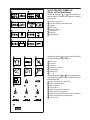
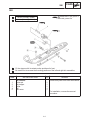
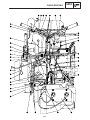
EXPLODED DIAGRAM
Each chapter provides exploded diagrams before each disassembly section to facilitate correct disassembly and assembly procedures.
ESS00006
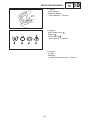
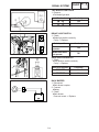
ILLUSTRATED SYMBOLS
(Refer to the illustration)
Illustrated symbols 1 to 8 are designed as
thumb tabs to indicate the chapter’s number
and content.
1 General information
2 Periodic inspection and adjustment
3 Chassis
4 Power train
5 Engine overhaul
6 Carburetion
7 Electrical
8 Specifications
Illustrated symbols 9 to 15 are used to identify
the specifications which appear.
9 Filling fluid
10
11
12
13
14
15
Lubricant
Tightening
Wear limit, clearance
Engine speed
Special tool
Ω, V, A
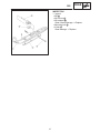
Illustrated symbols 16 to 24 in the exploded diagram indicate grade of lubricant and location of
lubrication point.
16
17
18
19
20
21
22
23
24
Apply locking agent (LOCTITE)
Apply Yamabond No.5
Apply engine oil
Apply gear oil
Apply molybdenum disulfide oil
Apply wheel bearing grease
Apply low-temperature lithium-soap base grease
Apply molybdenum disultide grease
Use new one
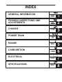
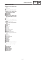
INDEX
GENERAL INFORMATION
GEN
INFO
1
PERIODIC INSPECTIONS AND
ADJUSTMENTS
INSP
ADJ
2
CHASSIS
CHAS
3
POWR
TR
4
ENG
5
CARB
6
ELEC
7
SPEC
8
POWER TRAIN
ENGINE
CARBURETION
ELECTRICAL
SPECIFICATIONS
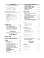
CHAPTER 1.
GENERAL INFORMATION
MACHINE IDENTIFICATION . . . . . . . . . . . 1-1
FRAME SERIAL NUMBER . . . . . . . . . . 1-1
ENGINE SERIAL NUMBER . . . . . . . . . 1-1
IMPORTANT INFORMATION . . . . . . . . . . . 1-2
PREPARATION FOR REMOVAL AND
DISASSEMBLY . . . . . . . . . . . . . . . . . . . . 1-2
ALL REPLACEMENT PARTS . . . . . . . . 1-3
GASKETS, OIL SEALS, AND
O-RINGS . . . . . . . . . . . . . . . . . . . . . . . . . 1-3
LOCK WASHERS/PLATES AND
COTTER PINS . . . . . . . . . . . . . . . . . . . . 1-3
BEARINGS AND OIL SEALS . . . . . . . . 1-3
CIRCLIPS . . . . . . . . . . . . . . . . . . . . . . . . . 1-4
LOCTITE . . . . . . . . . . . . . . . . . . . . . . . . 1-4
SPECIAL TOOLS . . . . . . . . . . . . . . . . . . . . . 1-5
FOR TUNE UP . . . . . . . . . . . . . . . . . . . . 1-5
FOR ENGINE SERVICE . . . . . . . . . . . . 1-5
FOR POWER TRAIN SERVICE . . . . . . 1-6
FOR CARBURETION SERVICE . . . . . 1-7
FOR ELECTRICAL SERVICE . . . . . . . 1-7
CHAPTER 2.
PERIODIC INSPECTIONS AND
ADJUSTMENTS
INTRODUCTION . . . . . . . . . . . . . . . . . . . . . . 2-1
PERIODIC MAINTENANCE TABLE . . . . . 2-1
ENGINE . . . . . . . . . . . . . . . . . . . . . . . . . . . . . 2-3
SPARK PLUGS . . . . . . . . . . . . . . . . . . . . 2-3
OIL PUMP . . . . . . . . . . . . . . . . . . . . . . . . 2-4
OIL FILTER INSPECTION . . . . . . . . . . 2-6
ENGINE OIL LINE INSPECTION . . . . . 2-6
FUEL LINE INSPECTION . . . . . . . . . . . 2-7
FUEL FILTER INSPECTION . . . . . . . . . 2-7
COOLING FAN BELT TENSION
ADJUSTMENT . . . . . . . . . . . . . . . . . . . . 2-9
ENGINE IDLE SPEED
ADJUSTMENT . . . . . . . . . . . . . . . . . . 2-10
THROTTLE CABLE FREEPLAY
ADJUSTMENT . . . . . . . . . . . . . . . . . . 2-10
THROTTLE OVERRIDE SYSTEM
(T.O.R.S.) CHECK . . . . . . . . . . . . . . . . 2-11
STARTER (CHOKE) CABLE
FREEPLAY ADJUSTMENT . . . . . . . 2-12
EXHAUST SYSTEM
INSPECTION . . . . . . . . . . . . . . . . . . . . 2-12
POWER TRAIN . . . . . . . . . . . . . . . . . . . . .
DRIVE V-BELT . . . . . . . . . . . . . . . . . .
SHEAVE DISTANCE AND OFFSET
ADJUSTMENT . . . . . . . . . . . . . . . . . .
ENGAGEMENT SPEED CHECK . . .
ADJUSTING THE BRAKE . . . . . . . . .
BRAKE PAD INSPECTION . . . . . . . .
DRIVE CHAIN . . . . . . . . . . . . . . . . . . .
TRACK TENSION ADJUSTMENT . .
SLIDE RUNNER INSPECTION . . . .
2-13
2-13
2-16
2-18
2-18
2-19
2-19
2-21
2-22
CHASSIS . . . . . . . . . . . . . . . . . . . . . . . . . .
SKI/SKI RUNNER . . . . . . . . . . . . . . . .
STEERING SYSTEM . . . . . . . . . . . . .
LUBRICATION . . . . . . . . . . . . . . . . . .
2-23
2-23
2-23
2-25
ELECTRICAL . . . . . . . . . . . . . . . . . . . . . .
HEADLIGHT BEAM
ADJUSTMENT . . . . . . . . . . . . . . . . . .
BATTERY INSPECTION . . . . . . . . . .
FUSE INSPECTION . . . . . . . . . . . . . .
2-27
TUNING . . . . . . . . . . . . . . . . . . . . . . . . . . .
CARBURETOR TUNING . . . . . . . . . .
CLUTCH . . . . . . . . . . . . . . . . . . . . . . . .
GEAR SELECTION . . . . . . . . . . . . . .
HIGH ALTITUDE TUNING . . . . . . . .
REAR SUSPENSION . . . . . . . . . . . . .
2-31
2-31
2-38
2-39
2-43
2-44
2-27
2-28
2-30
CHAPTER 3.
CHASSIS
STEERING . . . . . . . . . . . . . . . . . . . . . . . . . . . 3-1
INSPECTION . . . . . . . . . . . . . . . . . . . . . . 3-3
INSTALLATION . . . . . . . . . . . . . . . . . . . . 3-4
SKI . . . . . . . . . . . . . . . . . . . . . . . . . . . . . . . . . . 3-6
INSPECTION . . . . . . . . . . . . . . . . . . . . . . 3-7
FRONT SUSPENSION . . . . . . . . . . . . . . . . 3-8
HANDLING NOTES . . . . . . . . . . . . . . . . 3-9
INSPECTION . . . . . . . . . . . . . . . . . . . . . . 3-9
INSTALLATION . . . . . . . . . . . . . . . . . . 3-10
CYLINDER HEAD AND CYLINDER . . . . . 5-5
REMOVAL . . . . . . . . . . . . . . . . . . . . . . . . 5-6
INSPECTION . . . . . . . . . . . . . . . . . . . . . . 5-6
INSTALLATION . . . . . . . . . . . . . . . . . . . 5-11
CHAPTER 4.
POWER TRAIN
PRIMARY SHEAVE AND DRIVE
V-BELT . . . . . . . . . . . . . . . . . . . . . . . . . . . . . . 4-1
REMOVAL . . . . . . . . . . . . . . . . . . . . . . . . 4-3
DISASSEMBLY . . . . . . . . . . . . . . . . . . . . 4-4
INSPECTION . . . . . . . . . . . . . . . . . . . . . . 4-5
ASSEMBLY . . . . . . . . . . . . . . . . . . . . . . . 4-7
INSTALLATION . . . . . . . . . . . . . . . . . . . . 4-9
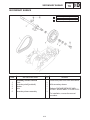
SECONDARY SHEAVE . . . . . . . . . . . . . .
DISASSEMBLY . . . . . . . . . . . . . . . . . .
INSPECTION . . . . . . . . . . . . . . . . . . . .
ASSEMBLY . . . . . . . . . . . . . . . . . . . . .
INSTALLATION . . . . . . . . . . . . . . . . . .
4-10
4-12
4-13
4-14
4-15
DRIVE CHAIN HOUSING . . . . . . . . . . . . 4-16
INSPECTION . . . . . . . . . . . . . . . . . . . . 4-18
INSTALLATION . . . . . . . . . . . . . . . . . . 4-22
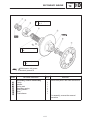
SECONDARY SHAFT (JACKSHAFT) . 4-23
INSPECTION . . . . . . . . . . . . . . . . . . . . 4-25
INSTALLATION . . . . . . . . . . . . . . . . . . 4-25
BRAKE . . . . . . . . . . . . . . . . . . . . . . . . . . . .
BRAKE PAD REPLACEMENT . . . . .
BRAKE CALIPER INSPECTION . . .
INSTALLATION . . . . . . . . . . . . . . . . . .
ENGINE ASSEMBLY . . . . . . . . . . . . . . . . . . 5-3
INSPECTION . . . . . . . . . . . . . . . . . . . . . . 5-4
INSTALLATION . . . . . . . . . . . . . . . . . . . . 5-4
4-26
4-27
4-30
4-31
OIL PUMP, CRANKCASE AND
CRANKSHAFT . . . . . . . . . . . . . . . . . . . . .
INSPECTION . . . . . . . . . . . . . . . . . . . .
OIL PUMP STROKE
ADJUSTMENT . . . . . . . . . . . . . . . . . .
INSTALLATION . . . . . . . . . . . . . . . . . .
OIL PUMP . . . . . . . . . . . . . . . . . . . . . .
5-14
5-15
5-16
5-18
5-19
CDI MAGNETO . . . . . . . . . . . . . . . . . . . . . 5-20
REMOVAL . . . . . . . . . . . . . . . . . . . . . . 5-21
INSTALLATION . . . . . . . . . . . . . . . . . . 5-22
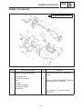
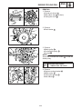
ENGINE COOLING FAN . . . . . . . . . . . . .
REMOVAL . . . . . . . . . . . . . . . . . . . . . .
INSPECTION . . . . . . . . . . . . . . . . . . . .
INSTALLATION . . . . . . . . . . . . . . . . . .
5-23
5-24
5-25
5-26
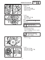
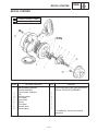
RECOIL STARTER . . . . . . . . . . . . . . . . . .
REMOVAL . . . . . . . . . . . . . . . . . . . . . .
INSPECTION . . . . . . . . . . . . . . . . . . . .
INSTALLATION . . . . . . . . . . . . . . . . . .
5-27
5-28
5-28
5-29
CHAPTER 6.
CARBURETION
SLIDE RAIL SUSPENSION . . . . . . . . . . 4-33
INSPECTION . . . . . . . . . . . . . . . . . . . . 4-37
INSTALLATION . . . . . . . . . . . . . . . . . . 4-37
CARBURETOR . . . . . . . . . . . . . . . . . . . . . . . 6-1
INSPECTION . . . . . . . . . . . . . . . . . . . . . . 6-3
ASSEMBLY . . . . . . . . . . . . . . . . . . . . . . . 6-4
INSTALLATION . . . . . . . . . . . . . . . . . . . . 6-5
FRONT AXLE AND TRACK . . . . . . . . . . 4-38
INSPECTION . . . . . . . . . . . . . . . . . . . . 4-40
INSTALLATION . . . . . . . . . . . . . . . . . . 4-40
FUEL PUMP . . . . . . . . . . . . . . . . . . . . . . . . . 6-6
INSPECTION . . . . . . . . . . . . . . . . . . . . . . 6-7
INSTALLATION . . . . . . . . . . . . . . . . . . . . 6-7
CHAPTER 5.
ENGINE
EXHAUST ASSEMBLY . . . . . . . . . . . . . . . . 5-1
INSPECTION . . . . . . . . . . . . . . . . . . . . . . 5-2
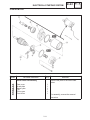
STARTER MOTOR . . . . . . . . . . . . . . . 7-21
CHAPTER 7.
ELECTRICAL
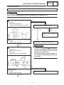
SWITCH INSPECTION . . . . . . . . . . . . . . . . 7-1
SWITCH INSPECTION . . . . . . . . . . . . . 7-1
INSPECTING A SWITCH SHOWN IN
THE MANUAL . . . . . . . . . . . . . . . . . . . . . 7-1
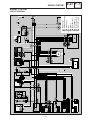
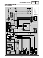
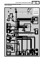
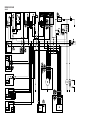
IGNITION SYSTEM . . . . . . . . . . . . . . . . . . . 7-2
CIRCUIT DIAGRAM . . . . . . . . . . . . . . . . 7-2
TROUBLESHOOTING . . . . . . . . . . . . . . 7-3
SPARK PLUG CAP . . . . . . . . . . . . . . . . 7-4
IGNITION COIL . . . . . . . . . . . . . . . . . . . . 7-4
SOURCE COIL/PULSER COIL . . . . . . 7-4
SPARK PLUG . . . . . . . . . . . . . . . . . . . . . 7-5
THROTTLE OVERRIDE SYSTEM
(T.O.R.S.) . . . . . . . . . . . . . . . . . . . . . . . . . 7-5
HANDLEBAR SWITCH (RIGHT) . . . . . 7-6
CARBURETOR SWITCH . . . . . . . . . . . 7-6
MAIN SWITCH . . . . . . . . . . . . . . . . . . . . 7-7
LIGHTING SYSTEM . . . . . . . . . . . . . . . . . . . 7-8
CIRCUIT DIAGRAM . . . . . . . . . . . . . . . . 7-8
TROUBLESHOOTING . . . . . . . . . . . . . . 7-9
BULB(S) . . . . . . . . . . . . . . . . . . . . . . . . 7-10
HEADLIGHT BEAM SWITCH . . . . . . 7-10
LIGHTING COIL . . . . . . . . . . . . . . . . . 7-10
SIGNAL SYSTEM . . . . . . . . . . . . . . . . . . . . 7-11
CIRCUIT DIAGRAM . . . . . . . . . . . . . . . 7-11
TROUBLESHOOTING . . . . . . . . . . . . 7-12
TROUBLESHOOTING . . . . . . . . . . . . 7-13
TAIL/BRAKE LIGHT BULB . . . . . . . . 7-14
BRAKE LIGHT SWITCH . . . . . . . . . . 7-14
GEAR POSITION SWITCH . . . . . . . . 7-14
BACK BUZZER . . . . . . . . . . . . . . . . . . 7-14
GRIP WARMER SYSTEM . . . . . . . . . . . .
CIRCUIT DIAGRAM . . . . . . . . . . . . . .
TROUBLESHOOTING . . . . . . . . . . . .
GRIP AND THUMB WARMER
COIL . . . . . . . . . . . . . . . . . . . . . . . . . . .
GRIP WARMER SWITCH . . . . . . . . .
7-15
7-15
7-16
ELECTRICAL STARTING SYSTEM . . .
CIRCUIT DIAGRAM . . . . . . . . . . . . . .
TROUBLESHOOTING . . . . . . . . . . . .
MAIN SWITCH . . . . . . . . . . . . . . . . . .
RECTIFIER . . . . . . . . . . . . . . . . . . . . .
7-18
7-18
7-19
7-20
7-20
7-17
7-17
CHARGING SYSTEM . . . . . . . . . . . . . . .
CIRCUIT DIAGRAM . . . . . . . . . . . . . .
TROUBLESHOOTING . . . . . . . . . . . .
BATTERY . . . . . . . . . . . . . . . . . . . . . . .
CHARGING COIL . . . . . . . . . . . . . . . .
7-24
7-24
7-25
7-26
7-26
CHAPTER 8.
SPECIFICATIONS
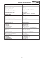
GENERAL SPECIFICATIONS . . . . . . . . . . 8-1
MAINTENANCE SPECIFICATIONS . . . . . 8-3
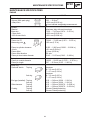
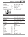
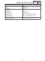
ENGINE . . . . . . . . . . . . . . . . . . . . . . . . . . 8-3
POWER TRAIN . . . . . . . . . . . . . . . . . . . . 8-6
CHASSIS . . . . . . . . . . . . . . . . . . . . . . . . . 8-9
ELECTRICAL . . . . . . . . . . . . . . . . . . . 8-10
HIGH ALTITUDE SETTINGS . . . . . . 8-12
TIGHTENING TORQUE . . . . . . . . . . 8-13
GENERAL TORQUE
SPECIFICATIONS . . . . . . . . . . . . . . . . . . 8-15
DEFINITION OF UNITS . . . . . . . . . . . . . . 8-15
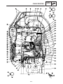
CABLE ROUTING . . . . . . . . . . . . . . . . . . 8-16
MACHINE IDENTIFICATION
GEN
INFO
ESS00011
GENERAL INFORMATION
ESS00012
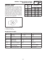
MACHINE IDENTIFICATION
ESS00013
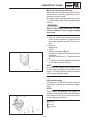
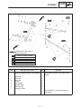
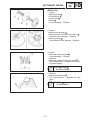
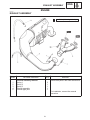
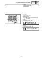
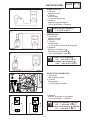
FRAME SERIAL NUMBER
The frame serial number 1 is located on the
right hand side of the frame (just below the front
of the seat).
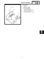
ESS00014
ENGINE SERIAL NUMBER
The engine serial number 2 is located on the
left hand side of the crankcase.
NOTE:
Designs and specifications are subject to
change without notice.
1-1
IMPORTANT INFORMATION
GEN
INFO
ESS00015
IMPORTANT INFORMATION
ESS00016
PREPARATION FOR REMOVAL AND DISASSEMBLY
1. Remove all dirt, mud, dust, and foreign material before removal and disassembly.
While cleaning, take care to protect the electrical parts, such as relays, switches, motor,
resistors, controllers, etc., from high pressure water splashes.
2. Use proper tools and cleaning equipment.
Refer to “SPECIAL TOOLS”.
3. When disassembling the machine, keep
mated parts together. This includes gears,
cylinders, pistons, and other parts that have
been “mated” through normal wear. Mated
parts must be reused or replaced as an assembly.
4. During disassembly of the machine, clean all
parts and place them in trays in the order of
disassembly. This will speed up assembly
time and help ensure that all parts are reinstalled correctly.
5. Keep all parts away from any source of fire.
6. Be sure to keep to the tightening torque
specifications. When tightening bolts, nuts,
and screws, start with those that have larger
diameters, and proceed from the inside to
the outside in a crisscross pattern.
1-2
1
IMPORTANT INFORMATION
GEN
INFO
ESS00017
ALL REPLACEMENT PARTS
We recommend using genuine Yamaha parts
for all replacements. Use oil and grease recommended by Yamaha for assembly and adjustments.
ESS00018
GASKETS, OIL SEALS, AND O-RINGS
1. All gaskets, seals, and O-rings should be replaced when an engine is overhauled. All
gasket surfaces, oil seal lips, and O-rings
must be cleaned.
2. Properly oil all mating parts and bearings
during reassembly. Apply grease to the oil
seal lips.
ESS00019
LOCK WASHERS/PLATES AND COTTER
PINS
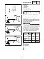
All lock washers/plates 1 and cotter pins must
be replaced if they are removed. Lock tab(s)
should be bent along the bolt or nut flat(s) after
the bolt or nut has been properly tightened.
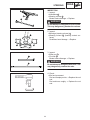
ESS00020
BEARINGS AND OIL SEALS
Install the bearings 1 and oil seals 2 with their
manufacturer’s marks or numbers facing outwards. (In other words, the stamped letters
must be on the side exposed to view.) When
installing oil seals, apply a light coating of lightweight lithium base grease to the seal lips. Oil
the bearings liberally when installing.
CAUTION:
Do not use compressed air to spin the bearings dry. This causes damage to the surface
of the bearings.
1-3
IMPORTANT INFORMATION
GEN
INFO
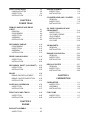
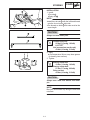
ESS00021
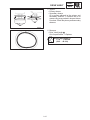
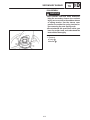
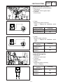
CIRCLIPS
All circlips should be inspected carefully before
reassembly. Always replace piston pin clips after one use. Replace misshapen circlips. When
installing a circlip 1 , make sure that the sharp
edged corner 2 is positioned opposite to the
thrust 3 it receives. See the sectional view.
4 Shaft
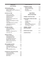
ESS00022
LOCTITE
After installing fasteners that have LOCTITE
applied, wait 24 hours before using the machine.
This will give the LOCTITE time to dry properly.
1-4
SPECIAL TOOLS
GEN
INFO
ESS00023
SPECIAL TOOLS
Some special tools are necessary for a completely accurate tune-up and assembly. Using
the correct special tool will help prevent damage that can be caused by the use of improper
tools or improvised techniques.
NOTE:
Be sure to use the correct part number when ordering the tool, since the part number may differ
according to country.
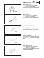
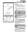
ESS00024
FOR TUNE UP
Sheave gauge
P/N: YS-39506-5 (16 mm offset)
This gauge is used to measure the sheave distance and for offset adjustment.
Dial gauge
P/N: YU-03097 (for U.S.A./Canada)
90890-03097 (for Europe)
This gauge is used for run out measurement.
Distance gauge
P/N: YS-91047-3 (for U.S.A./Canada)
90890-01702 (for Europe)
This gauge is used to measure the distance between the center of the primary sheave and the
center of the secondary sheave.
ESS00025
FOR ENGINE SERVICE
Piston pin puller
P/N: YU-01304 (for U.S.A./Canada)
90890-01304 (for Europe)
This tool is used to remove the piston pin.
1-5
SPECIAL TOOLS
GEN
INFO
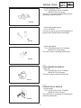
Rotor holding puller
P/N: YU-33270 (for U.S.A./Canada)
90890-01362 (for Europe)
This tool is used to remove the magneto rotor.
Rotor holding tool
P/N: YU-01235 (for U.S.A./Canada)
90890-01235 (for Europe)
This tool is used to remove the starter pulley.
ESS00026
FOR POWER TRAIN SERVICE
Primary sheave holder
P/N: YS-01880 (for U.S.A./Canada)
90890-01701 (for Europe)
This tool is used to hold the primary sheave.
Primary sheave puller
P/N: YS-01881-1 1 , YS-01882-1 2 (18 mm)
This tool is used for removing the primary
sheave.
Clutch spider separator
P/N: YS-28890-B (for U.S.A./Canada)
90890-01711 (for Europe)
This tool is used when disassembling and assembling the primary sheave.
1-6
SPECIAL TOOLS
GEN
INFO
Clutch separator adapter
P/N: YS-34480 (for U.S.A./Canada)
90890-01740 (for Europe)
This tool is used when disassembling and assembling the primary sheave.
YXR clutch bushing jig kit
P/N: YS-39752
This tool is used for removal and installation of
primary clutch weight and roller bushings.
Track clip installer
P/N: YS-91045-A (for U.S.A./Canada)
90890-01721 (for Europe)
This tool is used for installing the track clip.
ESS00027
FOR CARBURETION SERVICE
Mity vac
P/N: YB-35956 (for U.S.A./Canada)
90890-06756 (for Europe)
This tool is used to check the fuel pump.
ESS00028
FOR ELECTRICAL SERVICE
Pocket tester
P/N: YU-03112 (for U.S.A./Canada)
90890-03112 (for Europe)
This instrument is necessary for checking the
electrical components.
1-7
SPECIAL TOOLS
GEN
INFO
Electro tester
P/N: YU-33260-A (for U.S.A./Canada)
90890-03021 (for Europe)
This instrument is invaluable for checking the
electrical system.
1-8
INTRODUCTION/PERIODIC MAINTENANCE TABLE
INSP
ADJ
ESS00029
PERIODIC INSPECTIONS AND ADJUSTMENTS
ESS00030
INTRODUCTION
This chapter includes all information necessary to perform recommended inspections and adjustments.
These preventive maintenance procedures, if followed, will ensure more reliable machine operation
and a longer service life. In addition, the need for costly overhaul work will be greatly reduced. This
information applies to machines already in service as well as new machines that are being prepared for
sale.
All service technicians should be familiar with this entire chapter.
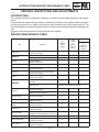
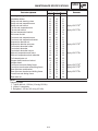
ESS00031
PERIODIC MAINTENANCE TABLE
Item
Spark plug
Engine oil
Preoperation
check
(Daily)
Remarks
Initial
1 month
or
800 km
(500 mi)
(40 hr)
Every
Seasonally
or
3,200 km
(2,000 mi)
(160 hr)
Check condition adjust the gap and clean.
Replace if necessary.
Check oil level.
Air bleed the oil pump if necessary.
Oil filter
Check condition.
Replace if necessary.
Fuel
Check fuel level.
Fuel filter
Check condition.
Replace if necessary.
Fuel line
Check fuel hose for cracks or damage.
Replace if necessary.
Oil line
Check oil hose for cracks or damage.
Replace if necessary.
Carburetor
Check throttle lever
operation.
Whenever operating condition
(elevation / temperature) is changed.
Adjust the jets.
Fan belt
Check wear and damage.
Replace if necessary.
Adjust fan belt if necessary.
Manual starter
Check operation and rope damage.
Replace if necessary.
Engine stop switch
Check operation.
Repair if necessary.
Throttle override
system
Check operation.
Repair if necessary.
Throttle lever
Check operation.
Repair if necessary.
Exhaust system
Check for leakage.
Retighten or replace gasket if necessary.
Decarbonization
More frequently if necessary.
Drive V-belt guard
Check cracks, bends or damage.
Replace if necessary.
Drive V-belt
Check wear and damage.
Replace if necessary.
2-1
INSP
ADJ
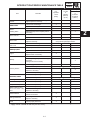
INTRODUCTION/PERIODIC MAINTENANCE TABLE
Item
Drive track / Idler
wheels
Slide runners
Brake /
Parking brake
Drive chain oil
Drive chain
Ski /
Ski runner
Steering system
Lights
Battery
Preoperation
check
(Daily)
Remarks
Check deflection, wear and damage.
Adjust / replace if necessary.
Check wear and damage.
Secondary sheave
Every
Seasonally
or
3,200 km
(2,000 mi)
(160 hr)
Replace if necessary.
Check operation.
Adjust free play and / or replace pads if
necessary.
Check oil level.
Replace.
**
Check deflection.
Adjust if necessary.
Initial at 480 km (300 Mi) and
every 800 km (500 Mi) thereafter.
Check wear and damage.
Replace if necessary.
Check operation.
Adjust toe-out if necessary.
Check operation.
Replace bulbs if necessary.
Check fluid level.
Check specific gravity and breather pipe
operation.
Charge / Correct if necessary.
Check engagement and shift speed.
Adjust if necessary.
Primary sheave
Initial
1 month
or
800 km
(500 mi)
(40 hr)
Whenever operating elevation is changed.
Check wear and damage.
Replace if necessary.
Lubricate with specified grease.
Lubricate with specified grease.
Adjust if necessary.
Whenever operating elevation is changed.
Steering column bearing
Lubricate with specified grease.
Ski and front suspension
Lubricate with specified grease.
Suspension component
Lubricate with specified grease.
Brake cable end and
lever end / Throttle cable
end
Lubricate with specified grease.
Check cable damage.
Replace if necessary.
Shroud latches
Make sure the shroud
Iatches are hooked.
Fittings / Fasteners
Check tightness.
Repair if necessary.
Service tools / Spare
parts
Check proper placement.
** Apply “initial 1 month or 400 km (250 mi, 20 hr)”
2-2
2
SPARK PLUGS
INSP
ADJ
ESS00032
ENGINE
ESS00033
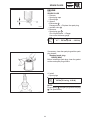
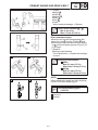
SPARK PLUGS
1. Remove:
S Spark plug caps
S Spark plugs
2. Inspect:
S Electrodes 1
Damage/wear Replace the spark plug.
S Insulator color 2
3. Measure:
S Spark plug gap a
Out of specification Regap.
Use a wire thickness gauge.
Spark plug gap a :
0.7 0.8 mm (0.028 0.032 in)
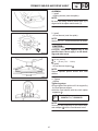
If necessary, clean the spark plugs with a spark
plug cleaner.
Standard spark plug:
BR9ES (NGK)
Before installing a spark plug, clean the gasket
surface and spark plug surface.
4. Install:
S Spark plugs
Spark plug:
20 Nm (2.0 mSkg, 14 ftSlb)
NOTE:
Finger-tighten a the spark plug before torquing
b it to specification.
2-3
OIL PUMP
INSP
ADJ
ESS00034
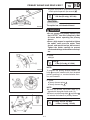
OIL PUMP
ESS00035
Air bleeding
CAUTION:
The oil pump and oil delivery line must be
bled in the following cases:
S Any portion of the oil system has been disconnected.
S The machine has been turned on its side.
S The oil tank has been run empty.
S As part of the pre-delivery service.
1. Fill:
S Oil tank 1
Recommended oil:
YAMALUBE 2-cycle oil
Oil tank capacity:
2.5 L (2.2 Imp qt, 2.6 US qt)
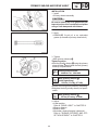
2. Remove:
S Drive V-belt guard
S Carburetors
Refer to “CARBURETORS” in CHAPTER 6.
3. Place a rag under the oil pump assembly to
soak up any spilled oil.
4. Disconnect:
S Oil hose 1
5. Drain the oil until no more air bubbles appear
in the oil hose 1 .
6. Connect:
S Oil hose 1
7. Disconnect:
S Oil delivery hoses 1
8. Feed the “YAMALUBE 2-cycle oil” into the oil
delivery hose using an oil can 2 for complete air bleeding.
9. Connect:
S Oil delivery hoses 1
2-4
OIL PUMP
INSP
ADJ
10. Remove:
S Bleed bolt 1
S Gasket (bleed bolt)
11. Drain the oil until no more air bubbles appear from the bleed hole.
12. Inspect:
S Gasket 1 (bleed bolt)
Damage/wear Replace.
13. Install:
S Gasket 1 (bleed bolt)
S Bleed bolt 2
14. Install:
S Carburetors
Refer to “CARBURETORS” in CHAPTER 6.
ESS00036
Cable adjustment
NOTE:
Before adjusting the oil pump cable, the throttle
cable distance should be adjusted.
Adjustment steps:
S Pull back the adjuster cover.
S Loosen the locknut 1 .
S Turn the adjuster 2 in or out until the specified
distance is obtained.
Oil pump cable adjusting length a :
24 26 mm (0.9 1.0 in)
Turning in Length a is increased.
Turning out Length a is decreased.
S Tighten the locknut 1 and push in the adjuster cover.
2-5
OIL FILTER INSPECTION/ENGINE OIL LINE INSPECTION
INSP
ADJ
OIL FILTER INSPECTION
1. Remove:
S Oil tank 1
2. Remove:
S Oil filter 1
NOTE:
Plug the oil hoses so that the oil will not run out
of the oil tank and oil pump.
3. Inspect:
S Oil filter 1
Contamination Replace.
Recommended replacement interval:
Every season
ENGINE OIL LINE INSPECTION
1. Inspect:
S Oil hoses 1
S Oil delivery hoses 2
Cracks/Damage Replace.
2-6
FUEL LINE INSPECTION/FUEL FILTER INSPECTION
INSP
ADJ
ESS00037
FUEL LINE INSPECTION
1. Inspect:
S Fuel hose 1
S Fuel delivery hoses 2
S Vacuum hose 3
Cracks/damage Replace.
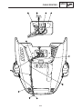
FUEL FILTER INSPECTION
1. Remove:
S Side cover (left 1 and right 2 )
S Plate 3
2. Remove:
S Main switch holding nut 1
S “STARTER” lever holding nut 2
S Grip warmer switch holding nut 3
3. Remove:
S Handlebar cover (lower) 1
4. Remove:
S Drive select lever boot 1
2-7
FUEL FILTER INSPECTION
INSP
ADJ
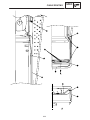
5. Remove:
S Seat 1
6. Remove:
S Fuel lever indicator hose 1
S Oil level indicator hose 2
S Center cover 3
7. Remove:
S Spring bands 1
S Cap 2
S Fuel filter 3
8. Inspect:
S Fuel filter 1
Contamination Replace.
Recommended replacement interval:
Every season
2-8
COOLING FAN BELT TENSION ADJUSTMENT
INSP
ADJ
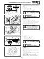
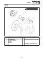
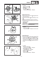
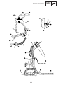
COOLING FAN BELT TENSION ADJUSTMENT
1. Adjust:
S Fan belt deflection a
Pushed at belt center by hand.
Out of specification Adjust.
Fan belt deflection a :
8 mm (0.31 in)/
4 6 kg (8.8 13.2 lb)
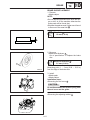
2. Adjust:
S Fan belt deflection.
Adjustment steps:
S Remove the recoil starter assembly, drive
pulley and fan belt.
S Remove the driven pulley (outer half) 1 and
shim(s) 2 .
S Adjust the drive belt tension by adding or removing a shim(s) 2 .
NOTE:
Install the removed shim(s) on the outside of the
driven pulley. Do not dispose of the removed
shim(s).
Adding shim Belt tension decreases.
Removing shim Belt tension increases.
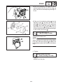
Shim size
Part number
Thickness
90214-17017
0.5 mm (0.02 in)
90214-17018
1.0 mm (0.04 in)
S Tighten the driven pulley nut 1 .
Driven pulley nut 1 :
43 Nm (4.3 mSkg, 31 ftSlb)
S Install the fan belt 2 and drive pulley 3 .
2-9
ENGINE IDLE SPEED ADJUSTMENT/
THROTTLE CABLE FREEPLAY ADJUSTMENT
INSP
ADJ
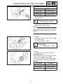
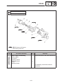
ESS00044
ENGINE IDLE SPEED ADJUSTMENT
1. Adjust:
S Engine idle speed
Adjustment steps:
S Start the engine and let it warm up.
S Turn the throttle stop screw 1 in or out until the
specified engine idle speed is obtained.
Turning in Idle speed is increased.
Turning out Idle speed is decreased.
Engine idle speed:
1,200 ± 100 r/min
NOTE:
After adjusting the engine idle speed, the
throttle cable freeplay should be adjusted.
ESS00046
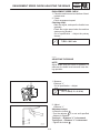
THROTTLE CABLE FREEPLAY ADJUSTMENT
NOTE:
Before adjusting the throttle cable freeplay, the
engine idle speed should be adjusted.
1. Measure:
S Throttle cable freeplay a
Out of specification Adjust.
Throttle cable freeplay a :
1.0 2.0 mm (0.04 0.08 in)
2. Adjust:
S Throttle cable freeplay
Adjustment steps:
S Loosen the locknut 1 .
S Turn the adjuster 2 in or out until the specified
freeplay is obtained.
Turning in Freeplay is increased.
Turning out Freeplay is decreased.
S Tighten the locknut 1 .
Lock nut 1 :
0.8 Nm (0.08 mSkg, 0.58 ftSlb)
NOTE:
After adjusting the freeplay, turn the handlebar
to right and left, and make sure that the engine
idling does not run faster.
2-10
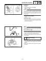
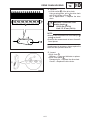
THROTTLE OVERRIDE SYSTEM (T.O.R.S.) CHECK
INSP
ADJ
ESS00048
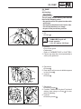
THROTTLE OVERRIDE SYSTEM (T.O.R.S.)
CHECK
WARNING
When checking T.O.R.S.:
S Be sure the parking brake is applied.
S Be sure the throttle lever moves smoothly.
S Do not run the engine up to the clutch engagement speed. Otherwise, the machine
could start moving forward unexpectedly,
which could cause an accident.
1. Start the engine.
2. Hold the pivot point of the throttle lever away
from the throttle switch by putting your thumb
(above) and forefinger (below) between the
throttle lever pivot 1 and stop switch housing 2 .
While holding as described above, press the
throttle lever 3 gradually.
The engine should stop immediately.
,,,,,,,,,,,,,,,,,,,,,,,,,,,,,,,,,,,,,,,,,,
,,,,,,,,,,,,,,,,,,,,,,,,,,,,,,,,,,,,,,,,,,
,,,,,,,,,,,,,,,,,,,,,,,,,,,,,,,,,,,,,,,,,,
,,,,,,,,,,,,,,,,,,,,,,,,,,,,,,,,,,,,,,,,,,
,,,,
,,,,,,,,,,,,,,,,,,,,,,,,,,,,,,,,,,,,,,,,,,
,,,,
,,,,,,,,,,,,,,,,,,,,,,,,,,,,,,,,,,,,,,,,,,
,,,,
,,,,,,,,,,,,,,,,,,,,,,,,,,,,,,,,,,,,,,,,,,
,,,,
,,,,,,,,,,,,,,,,,,,,,,,,,,,,,,,,,,,,,,,,,,
,,,,,,,,,,,,,,,,,,,,,,,,,,,,,,,,,,,,,,,,,,
,,,,,,,,,,,,,,,,,,,,,,,,,,,,,,,,,,,,,,,,,,
,,,,,,,,,,,,,,,,,,,,,,,,,,,,,,,,,,,,,,,,,,
,,,,,,,,,,,,,,,,,,,,,,,,,,,,,,,,,,,,,,,,,,
,,,,,,,,,,,,,,,,,,,,,,,,,,,,,,,,,,,,,,,,,,
,,,,,,,,,,,,,,,,,,,,,,,,,,,,,,,,,,,,,,,,,,
,,,,,,,,,,,,,,,,,,,,,,,,,,,,,,,,,,,,,,,,,,
,,,,,,,,,,,,,,,,,,,,,,,,,,,,,,,,,,,,,,,,,,
,,,,,,,,,,,,,,,,,,,,,,,,,,,,,,,,,,,,,,,,,,
,,,,,,,,,,,,,,,,,,,,,,,,,,,,,,,,,,,,,,,,,,
,,,,,,,,,,,,,,,,,,,,,,,,,,,,,,,,,,,,,,,,,,
,,,,,,,,,,,,,,,,,,,,,,,,,,,,,,,,,,,,,,,,,,
,,,,,,,,,,,,,,,,,,,,,,,,,,,,,,,,,,,,,,,,,,
,,,,,,,,,,,,,,,,,,,,,,,,,,,,,,,,,,,,,,,,,,
,,,,,,,,,,,,,,,,,,,,,,,,,,,,,,,,,,,,,,,,,,
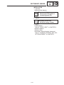
WARNING
If the engine does not stop, stop the engine
by turning the main switch to the “OFF”
position and check the electrical system.
,,,,,,,,,,,,,,,,,,,,,,,,
,,,,,,,,,,,,,,,,,,,,,,,,
,,,,,,,,,,,,,,,,,,,,,,,,
,,,,,,,,,,,,,,,,,,,,,,,,
,,,,,,,,,,,,,,,,,,,,,,,,
,,,,,,,,,,,,,,,,,,,,,,,,
,,,,,,,,,,,,,,,,,,,,,,,,
,,,,,,,,,,,,,,,,,,,,,,,,
,,,,,,,,,,,,,,,,,,,,,,,,
,,,,,,,,,,,,,,,,,,,,,,,,
,,,,,,,,,,,,,,,,,,,,,,,,
,,,,,,,,,,,,,,,,,,,,,,,,
,,,,,,,,,,,,,,,,,,,,,,,,
,,,,,,,,,,,,,,,,,,,,,,,,
,,,,,,,,,,,,,,,,,,,,,,,,
,,,,,,,,,,,,,,,,,,,,,,,,
,,,,,,,,,,,,,,,,,,,,,,,,
,,,,,,,,,,,,,,,,,,,,,,,,
,,,,,,,,,,,,,,,,,,,,,,,,
,,,,,,,,,,,,,,,,,,,,,,,,
,,,,,,,,,,,,,,,,,,,,,,,,
,,,,,,,,,,,,,,,,,,,,,,,,
,,,,,,,,,,,,,,,,,,,,,,,,
,,,,,,,,,,,,,,,,,,,,,,,,
,,,,,,,,,,,,,,,,,,,,,,,,
2-11
STARTER (CHOKE) CABLE FREEPLAY ADJUSTMENT/
EXHAUST SYSTEM INSPECTION
INSP
ADJ
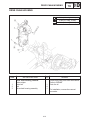
ESS00050
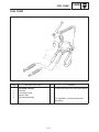
STARTER (CHOKE) CABLE FREEPLAY ADJUSTMENT
1. Pull back the starter cable outer tube 1 .
2. Measure:
S Starter cable freeplay a
Out of specification Adjust.
Starter cable freeplay a :
0.5 1.5 mm (0.02 0.06 in)
3. Adjust:
S Starter cable freeplay
Adjustment steps:
S Pull back the adjuster cover 1 .
S Loosen the locknut 2 .
S Turn the adjuster 3 in or out until the specified
freeplay is obtained.
Turning in Freeplay is increased.
Turning out Freeplay is decreased.
S Tighten the locknut and push in the adjuster
cover.
ESS00053
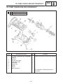
EXHAUST SYSTEM INSPECTION
1. Remove:
S Springs
Refer to “EXHAUST ASSEMBLY” in CHAPTER 5.
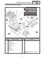
2. Inspect:
S Exhaust joint 1
S Exhaust pipe 2
S Exhaust silencer 3
Cracks/damgae Replace.
S Exhaust gaskets 4
Exhaust gas leaks Replace.
3. Check:
S Tightening torque
Bolt (exhaust pipe joint):
30 Nm (3.0 mSkg, 22 ftSlb)
4. Install:
S Springs
Refer to “EXHAUST ASSEMBLY” in CHAPTER 5.
2-12
DRIVE V-BELT
INSP
ADJ
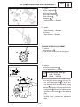
ESS00054
POWER TRAIN
ESS00055
,,,,
,,,
,,,,
,,,,
,,,,
,,,,
,,,,,,,
,,,,,,,,
,,,,
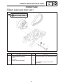
DRIVE V-BELT
1. Remove:
S Drive V-belt guard 1
,,,
,,,
,,,
,,,
,,,
,,,
WARNING
S Be sure there are shims (2 pcs) 1 between
secondary fixed and sliding sheaves when
installing the NEW belt.
S If there is no gap, the clutch engagement
speed will be reduced. The machine may
move unexpectedly when the engine is
started.
S The spacer of the secondary sheave
should be adjusted.
CAUTION:
To ensure proper clutch performance, the
spacers in the secondary clutch must be repositioned as the V-belt wears.
New belt width:
35.0 mm (1.38 in)
Belt wear limit width:
32.0 mm (1.26 in)
2. Measure:
S V-belt height a
Out of specification Adjust.
,,,,,,,,,,,,,,,,,,,,,,,
,,,,,,,,,,,,,,,,,,,,,,,
,,,,,,,,,,,,,,,,,,,,,,,
,,,,,,,,,,,,,,,,,,,,,,,
,,,,,,,,,,,,,,,,,,,,,,,
,,,,,,,,,,,,,,,,,,,,,,,
,,,,,,,,,,,,,,,,,,,,,,,
,,,,,,,,,,,,,,,,,,,,,,,
,,,,,,,,,,,,,,,,,,,,,,,
,,,,,,,,,,,,,,,,,,,,,,,
,,,,,,,,,,,,,,,,,,,,,,,
,,,,,,,,,,,,,,,,,,,,,,,
Standard V-belt height
(Below sheave surface) a :
0 2 mm (0 0.08 in)
2-13
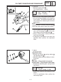
DRIVE V-BELT
INSP
ADJ
V-belt width 1
Number
of spacers
A
35 mm (1.38 in) or more
2 spacers
B
34 mm (1.34 in)
1 spacer
C
33 mm (1.30 in)
No spacer
32 mm (1.26 in) or less
Replace the
V-belt
3. Remove:
S Drive V-belt 1
Removal steps:
S Rotate the secondary sliding sheave clockwise 2 and push it 3 so that it separates from
the fixed sheave.
S Pull 4 the belt up over the secondary fixed
sheave.
S Remove the belt from the secondary sheave
and primary sheave.
4. Inspect:
S Drive V-belt
Crack/Wear/Damage Replace.
Oil or grease adhered to the V-belt Check
the primary and secondary sheaves.
2-14
DRIVE V-BELT
INSP
ADJ
5. Inspect:
S Primary sheave
S Secondary sheave
Oil or grease adhered to the primary and
secondary sheaves Remove the oil or
grease using a rag soaked in lacquer thinner
or solvent. Check the primary and secondary
sheaves.
6. Measure:
S Drive V-belt length a
Out of specification Replace.
Drive V-belt length a :
1,118 1,128 mm
(44.0 44.4 in)
2-15
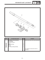
SHEAVE DISTANCE AND OFFSET ADJUSTMENT
INSP
ADJ
ESS00055
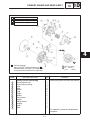
SHEAVE DISTANCE AND OFFSET ADJUSTMENT
1. Measure:
S Sheave distance a
Use the sheave gauge.
Out of specification Adjust.
,,,,,,,,,,,,,,,,,,,,,,,,,,,,,,,,,,,,,,,,,,,,,,,,,,
,,,,,,,,,,,,,,,,,,,,,,,,,,,,,,,,,,,,,,,,,,,,,,,,,,
,,,,,,,,,,,,,,,,,,,,,,,,,,,,,,,,,,,,,,,,,,,,,,,,,,
,,,,,,,,,,,,,,,,,,,,,,,,,,,,,,,,,,,,,,,,,,,,,,,,,,
Sheave distance a :
267 270 mm (10.5 10.6 in)
Sheave gauge:
90890-01702, YS-91047-3
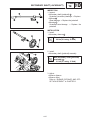
2. Adjust:
S Sheave distance
Adjustment steps:
S Loosen the engine mounting bolts.
S Adjust the position of the engine so that the
sheave distance is within the specification.
S Tighten the engine mounting bolts.
Mounting bolt (front) 1 :
103 Nm (10.3 mSkg, 74 ftSlb)
Mounting bolt (front) (rear) 2 :
53 Nm (5.3 mSkg, 38 ftSlb)
3. Measure:
S Sheave offset b
Use the sheave gauge.
Out of specification Adjust.
,,,,,,,,,,,,,,,,,,,,,,,,,,,,,,,,,,,,,,,,,,,,,,,,,,,,,,,,,,,,,,,
,,,,,,,,,,,,,,,,,,,,,,,,,,,,,,,,,,,,,,,,,,,,,,,,,,,,,,,,,,,,,,,
,,,,,,,,,,,,,,,,,,,,,,,,,,,,,,,,,,,,,,,,,,,,,,,,,,,,,,,,,,,,,,,
,,,,,,,,,,,,,,,,,,,,,,,,,,,,,,,,,,,,,,,,,,,,,,,,,,,,,,,,,,,,,,,
Sheave offset b :
14.5 17.5 mm (0.57 0.69 in)
Sheave gauge:
90890-01702, YS-39506-5
4. Adjust:
S Sheave offset
Adjustment steps:
S Apply the brake to lock the secondary sheave.
S Remove the bolt (secondary sheave) and secondary sheave 1 .
S Adjust the sheave offset by adding or removing shim(s) 2 .
Adding shim Offset is increased.
Removing shim Offset is decreased.
2-16
SHEAVE DISTANCE AND OFFSET ADJUSTMENT
INSP
ADJ
Shim size
Part Number
Thickness
90201-252F1
0.5 mm (0.02 in)
90201-25527
1.0 mm (0.04 in)
90201-25526
2.0 mm (0.08 in)
S Install the secondary sheave and bolt (secondary sheave).
Bolt (secondary sheave):
60 Nm (6.0 mSkg, 43 ftSlb)
S Recheck the sheave offset. If out of specification, repeat the above steps.
NOTE:
When adjusting the sheave offset, the secondary sheave free play (clearance) should be adjusted.
5. Measure:
S Secondary sheave freeplay (clearance) c
Use a feeler gauge.
Out of specification Adjust.
Secondary sheave freeplay
(clearance) c :
1.5 2.0 mm (0.06 0.08 in)
6. Adjust:
S Secondary sheave freeplay (clearance)
Adjustment steps:
S Apply the brake to lock the secondary sheave.
S Remove the bolt 1 and washer 2 .
S Adjust the secondary sheave freeplay (clearance) by adding or removing a shim(s) 3 .
Shim size:
2-17
Part number
Thickness
90201-252F1
0.5 mm (0.02 in)
90201-25527
1.0 mm (0.04 in)
90201-25526
2.0 mm (0.08 in)
ENGAGEMENT SPEED CHECK/ADJUSTING THE BRAKE
INSP
ADJ
ESS00057
ENGAGEMENT SPEED CHECK
1. Place the machine on a level surface of hardpacked snow.
2. Check:
S Clutch engagement speed
Checking steps:
S Start the engine, and open the throttle lever
gradually.
S Check the engine speed when the machine
starts moving forward.
Out of specification Adjust the primary
sheave.
Engagement speed:
2,600 ± 200 r/min
ESS00060
ADJUSTING THE BRAKE
NOTE:
Adjust brake every 40 hours of operation, or
whenever the brake lever becomes loose during operation.
1. Measure:
S Distance “L”
Out of specification Adjust.
Distance “L”
54 ± 1 mm (2.13 ± 0.04 in)
2. Adjust
S Distance “L”
Adjustment steps:
S Loosen the locknut 1 .
S Turn the adjuster 2 in or out until specified
distance is obtained.
Turning in Distance “L” is increased.
Turning out Distance “L” is decreased.
S Tighten the locknut 1 .
2-18
BRAKE PAD INSPECTION/DRIVE CHAIN
INSP
ADJ
ESS00062
BRAKE PAD INSPECTION
1. Apply the brake lever.
2. Inspect:
S Brake pad thickness a
Out of specification Replace brake pad as
a set.
Wear limit a :
10 mm (0.39 in)
ESS00065
DRIVE CHAIN
ESS00066
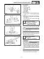
Oil level inspection
WARNING
The engine and muffler will be very hot after
the engine has run. Avoid touching a hot engine and muffler while they are still hot with
any part of your body or clothing during inspection or repair.
1. Place the machine on a level surface.
2. Remove:
S Muffler
3. Place a rag under the checking hole 1 (oil
level).
4. Remove:
S Filler cap 1
S Checking screw 2
S Gasket (checking screw)
5. Inspect:
S Oil level (drive chain housing)
Oil flows out Oil level is correct.
Oil does not flow out Oil level is low.
Add oil until oil flows out.
Recommended oil:
Gear oil API GL-3 SAE
#75 or #80
6. Inspect:
S Gasket (checking screw)
Damage Replace.
2-19
DRIVE CHAIN
INSP
ADJ
ESS00067
Oil replacement
Oil replacement steps:
S Place the oil pan under the drain hole 1 .
S Remove the oil drain bolt 2 and drain the oil.
CAUTION:
Be sure to remove any oil from the heat protector.
S Install the oil drain bolt 2 .
Oil drain bolt:
10 Nm (1.0 mSkg, 7.2 ftSlb)
Recommended oil:
Gear oil API GL-3 SAE
#75 or #80
Oil capacity:
0.35 L (12.3 Imp oz, 11.8 US oz)
ESS00068
Chain slack adjustment
1. Adjust:
S Drive chain slack
Adjustment steps:
S Loosen the locknut 1 .
S Shift the shift lever to the “FORWARD” position.
S Turn the secondary sheave one turn counterclockwise.
S Slide the seal washer 3 from the case surface
4.
S Turn in the adjusting bolt 2 , until it lightly the
contacts tensioner, then turn in the adjusting
bolt 2 1/2 to 2/3 turn more.
S Tighten the locknut 1 .
2-20
TRACK TENSION ADJUSTMENT
INSP
ADJ
ESS00069
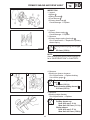
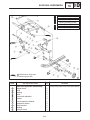
TRACK TENSION ADJUSTMENT
WARNING
A broken track or track fittings, and debris
thrown by the track could be dangerous to
an operator or bystanders. Observe the following precautions.
S Do not allow anyone to stand behind the
machine when the engine is running.
S When the rear of the machine is raised to
allow the track to spin, a suitable stand
must be used to support the rear of the machine.
Never allow anyone to hold the rear of the
machine off the ground to allow the track to
spin. Never allow anyone near a rotating
track.
S Inspect the condition of the track frequently.
Replace the track if it is damaged to a level
where the fabric reinforcement material is
visible.
S Never install studs (cleats) closer than
76 mm (3 in) to the edge of the track.
1. Place the machine with the right side facing
down.
CAUTION:
If the machine is left on its left side for more
than 80 minutes, the fuel may leak out from
the fuel breather hose.
2. Measure:
S Track deflection a
Using a spring scale 1 , pull down on the
center of the track with 10 kg (22 lb) of force.
Out of specification Adjust.
Track deflection a :
35 45 mm (1.4 1.8 in)
3. Adjust:
S Track deflection
Adjustment steps:
S Place the machine onto a suitable stand to
raise the track off of the ground.
S Loosen the rear axle nut 1 .
NOTE:
It is not necessary to remove the cotter pin 2 .
2-21
TRACK TENSION ADJUSTMENT/
SLIDE RUNNER INSPECTION
INSP
ADJ
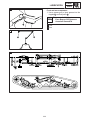
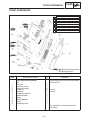
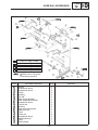
a. Start the engine and rotate the track once or
twice. Stop the engine.
b. Check the track alignment with the slide runner 3 .
If the alignment is incorrect, turn the left and
right adjusters to adjust.
Track alignment
6 Shifted
to right
7 Shifted
to left
4 Left adjuster
Turn out
Turn in
5 Right adjuster Turn in
8 Slide runner
9 Track
10 Track metal
11 Gap
Turn out
12 Forward
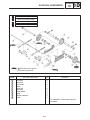
c. Adjust the track deflection until the specified
amount is obtained.
Track deflection
More than
specified
Less than
specified
4 Left adjuster
Turn in
Turn out
5 Right adjuster Turn in
Turn out
CAUTION:
The adjusters should be turned an equal
amount.
S Recheck the alignment and deflection. If necessary, repeat steps (a) to (c) until the specified amount is obtained.
S Tighten the rear axle nut.
Nut (rear axle):
80 Nm (8.0 mSkg, 58 ftSlb)
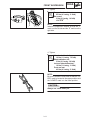
ESS00070
SLIDE RUNNER INSPECTION
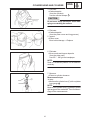
1. Inspect:
S Slide runner 1
Cracks/damage/wear Replace the slide
runner.
2. Measure:
S Slide runner thickness a
Out of specificaiton Replace the slide runner.
Slide runner wear limit a :
10 mm (0.39 in)
2-22
SKI/SKI RUNNER/STEERING SYSTEM
INSP
ADJ
ESS00071
CHASSIS
ESS00072
SKI/SKI RUNNER
1. Check:
S Ski
S Ski runner
Wear/Damage Replace.
Ski runner wear limit 1 :
4.5 mm (0.18 in)
ESS00073
STEERING SYSTEM
ESS00074
Freeplay check
1. Check:
S Steering system freeplay
Move the handlebar up and down and back
and forth.
Turn the handlebar slightly to the right and
left.
Excessive freeplay Check that the handlebar, tie rod ends and relay rod ends are
installed securely in position. If freeplay still
exists, check the steering bearing, front suspension links and ski mounting area for wear.
Replace if necessary.
2-23
STEERING SYSTEM
INSP
ADJ
ESS00075
Toe-out adjustment
1. Place the machine on a level surface.
2. Check:
S Ski toe-out
Point the skis forward.
Out of specification Adjust.
Ski toe-out ( a – c ):
0 15 mm (0 0.59 in)
Ski stance b (center to center):
960 mm (37.8 in)
3. Adjust:
S Ski toe-out
Adjustment steps:
S Loosen the locknuts (tie-rod) 1 .
S Turn the tie-rod 2 in or out until the specified
toe-out is obtained.
S Tighten the locknuts (tie-rod) 1 .
A
Locknut (rod end):
25 Nm (2.5 mSkg, 18 ftSlb)
LOCTITE
B
CAUTION:
After tightening the inside and outside ball
joint locknut 1 , make sure the tie-rod 2 can
be rotated freely through the ball joint travel.
If not, loosen the locknut 1 and re-position
the ball joint so that the tie-rod 2 can be rotated freely. Tighten the locknut to specification.
A Left side
B Right side
2-24
LUBRICATION
INSP
ADJ
ESS00076
LUBRICATION
ESS00077
Brake lever, throttle lever and throttle cable
end
1. Lubricate the brake lever pivot, throttle lever
and the ends of the throttle cable and brake
cable.
Recommended lubricant:
Esso Beacon 325 Grease
WARNING
Apply a dab of grease onto only the end of
the cable.
Do not grease the throttle cables.
They could freeze and cause a loss of control.
2-25
LUBRICATION
INSP
ADJ
ESS00078
A
Front and rear suspension
1. Use a grease gun to inject grease into the
nipples 1 and ball joints 2 .
Recommended lubricant:
Esso Beacon 325 Grease or
Aeroshell Grease #7A
A Front
B Rear
A
B
2-26
HEADLIGHT BEAM ADJUSTMENT
INSP
ADJ
ESS00079
ELECTRICAL
ESS00080
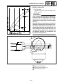
HEADLIGHT BEAM ADJUSTMENT
1. Place the machine on a level surface.
2. Measure the distance from the floor to the
center of the headlight and place a mark on
the wall equal to distance H from the floor.
3. Place the machine from the wall at a distance
D indicated by the chart below.
4. With a person sitting on the machine, apply
the parking brake, start the engine and let it
idle.
5. Turn the headlight to high beam and check
the headlight projection height on the wall.
The projection should be at the parallel mark
on the wall H to 1/2_ down S from the mark.
If not, adjust the headlight angle.
D
3.0 m (10 ft)
7.6 m (25 ft)
S
26 mm (1.0 in)
66 mm (2.6 in)
D : Distance
S : Set range
6. Adjust:
S Headlight beam (vertically)
Vertical adjustment
Higher Turn the adjusting screw 1 counterclockwise.
Lower
Turn the adjusting screw 1 clockwise.
7. Adjust:
S Headlight beam (horizontally)
Horizontal adjustment
Right
Turn the adjusting screw 1 counterclockwise.
Left
Turn the adjusting screw 1 clockwise.
2-27
BATTERY INSPECTION
INSP
ADJ
ESS00081
BATTERY INSPECTION
WARNING
Battery electrolyte is dangerous; it contains
sulfuric acid and therefore is poisonous and
highly caustic.
Always follow these preventive measures:
S Avoid bodily contact with electrolyte as it
can cause severe burns or permanent eye
injury.
S Wear protective eye gear when handling or
working near batteries.
Antidote (EXTERNAL):
S SKIN – Flush with water.
S EYES – Flush with water for 15 minutes and
get immediate medical attention.
Antidote (INTERNAL):
S Drink large quantities of water or milk, and
follow with milk of magnesia, beaten egg,
or vegetable oil. Get immediate medical
attention.
Batteries also generate explosive hydrogen
gas, therefore, you should always follow
these preventive measures:
S Charge batteries in a well-ventilated area.
S Keep batteries away from fire, sparks, or
open flames (e.g., welding equipment,
lighted cigarettes, etc.)
S DO NOT SMOKE when charging or handling batteries.
KEEP BATTERIES AND ELECTROLYTE OUT
OF REACH OF CHILDREN.
1. Remove:
S Battery holder 1
S Battery
2. Inspect:
S Battery fluid level
Fluid level should be between upper 1 and
lower 2 level marks.
Incorrect Refill.
,,,,,,,,,,,,,,,,,,,,,,,,,,,,
,,,,,,,,,,,,,,,,,,,,,,,,,,,,
,,,,,,,,,,,,,,,,,,,,,,,,,,,,
,,,,,,,,,,,,,,,,,,,,,,,,,,,,
,,,,,,,,,,,,,,,,,,,,,,,,,,,,
,,,,,,,,,,,,,,,,,,,,,,,,,,,,
,,,,,,,,,,,,,,,,,,,,,,,,,,,,
,,,,,,,,,,,,,,,,,,,,,,,,,,,,
,,,,,,,,,,,,,,,,,,,,,,,,,,,,
,,,,,,,,,,,,,,,,,,,,,,,,,,,,
,,,,,,,,,,,,,,,,,,,,,,,,,,,,
,,,,,,,,,,,,,,,,,,,,,,,,,,,,
,,,,,,,,,,,,,,,,,,,,,,,,,,,,
,,,,,,,,,,,,,,,,,,,,,,,,,,,,
,,,,,,,,,,,,,,,,,,,,,,,,,,,,
,,,,,,,,,,,,,,,,,,,,,,,,,,,,
,,,,,,,,,,,,,,,,,,,,,,,,,,,,
,,,,,,,,,,,,,,,,,,,,,,,,,,,,
,,,,,,,,,,,,,,,,,,,,,,,,,,,,
CAUTION:
Refill with distilled water only; tap water
contains minerals harmful to a battery.
2-28
BATTERY INSPECTION
INSP
ADJ
3. Check:
S Specific gravity
Less than 1.280 Recharge battery.
Charging current:
1.4 amps/10 hrs
Specific gravity:
1.280 at 20_C (68_F)
Replace the battery if:
S Battery voltage will not rise to a specific value
or if bubbles fail to rise even after many hours
of charging.
S Sulfation of one or more cells occurs, as indicated by the plates turning white, or if an accumulation of material exists in the bottom of the
cell.
S Specific gravity readings after a long, slow
charge indicate one cell to be lower than the
rest.
S Warpage or buckling of plates or insulators is
evident.
CAUTION:
Always charge a new battery before using it
to ensure maximum performance.
4. Install:
S Battery
S Battery holder
CAUTION:
,,,,,,,,,,,,,,,,,,,,,,
,,,,,,,,,,,,,,,,,,,,,,
,,,,,,,,,,,,,,,,,,,,,,
,,,,,,,,,,,,,,,,,,,,,,
,,,,,,,,,,,,,,,,,,,,,,
,,,,,,,,,,,,,,,,,,,,,,
,,,,,,,,,,,,,,,,,,,,,,
,,,,,,,,,,,,,,,,,,,,,,
,,,,,,,,,,,,,,,,,,,,,,
,,,,,,,,,,,,,,,,,,,,,,
,,,,,,,,,,,,,,,,,,,,,,
,,,,,,,,,,,,,,,,,,,,,,
,,,,,,,,,,,,,,,,,,,,,,
Connect the positive lead 1 first and then
connect the negative lead 2 .
2-29
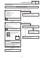
FUSE INSPECTION
INSP
ADJ
FUSE INSPECTION
1. Remove:
S Fuse 1
S Spare fuse 2
2. Inspect:
S Fuse
Inspection:
S Connect a pocket tester to the fuse and check
it for continuity.
NOTE:
Set the tester selector to “Ω
1” position.
Pocket tester:
90890-03112, YU-03112
S If the tester indicates ∞ the fuse is blown.
It must be replaced.
3. Replace:
S Blown fuse
Replacement steps:
S Turn off the ignition and the circuit.
S Install a new fuse of proper amperage.
S Turn on the switches to verify operation of the
electrical device.
S If the fuse blows again immediately, check the
circuit in question.
NOTE:
Install new fuses of proper amperage.
Description
Amperage
Quantity
Main
10A
1
Spare
10A
1
WARNING
Do not use fuses of higher amperage rating
than that which is recommended. Extensive
electrical system damage and fire could result from the substitution of a fuse of improper amperage.
2-30
INSP
ADJ
CARBURETOR TUNING
ESS00083
TUNING
ESS00084
CARBURETOR TUNING
The carburetors are set at the factory to run at
temperatures of 0_C –20_C (32_F –4_F)
at sea level. If the machine is to be operated under conditions other than those specified
above, the carburetors must be properly adjusted. Special care should be taken in carburetor setting so that the pistons will not be damaged or will not seize.
CAUTION:
Engine oil is mixed with fuel just before the
fuel enters the carburetors. During initial
fuel flow to the carburetors, it is not always
possible to supply the optimum fuel/oil mixture depending on the throttle opening.
Therefore, after the carburetors have been
tuned or maintained, or after the float chambers are removed for cleaning or jet replacement, be sure to idle the engine for about
three minutes in order to avoid engine
trouble.
CAUTION:
Before performing the carburetor tuning,
make sure that the following items are set to
specification.
S Engine idle speed
S Throttle cable freeplay
S Carburetor synchronization
S Starter cable freeplay
S Oil pump cable freeplay
ESS00085
Carburetor tuning data
1. Standard specifications
2-31
A Type
B38-34/1
B Manufacturer
MIKUNI
C Main jet (M.J.)
#141.3
D Pilot jet (P.J.)
#90
E Pilot screw (P.S.)
1-1/4 turn out
F Float height
12 16 mm
(0.47 0.63 in)
G Idle speed
1,200 ± 100 r/min
CARBURETOR TUNING
INSP
ADJ
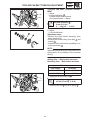
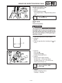
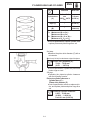
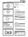
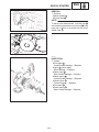
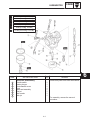
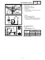
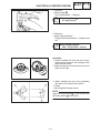
ESS00066
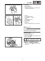
Mid-range and high speed tuning
Adjustments are normally not required, but may
sometimes be necessary, depending on temperatures, altitude or both.
Mid-range speed and high speed tuning (from
1/4 to full-throttle) can be done by adjusting the
main jet.
CAUTION:
Never run the engine without the air intake
silencer installed. Severe engine damage
may result.
1. Start the engine and operate the machine
under normal conditions to make sure that
the engine operates smoothly. Stop the engine.
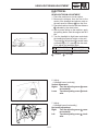
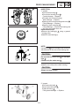
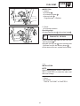
2. Remove:
S Spark plugs
3. Check:
S Spark plug insulator 1 color
A medium to light tan color indicates normal
conditions.
Distinctly different color Replace the main
jet.
4. The main jet should be adjusted on the basis
of the “Main jet selection chart”.
NOTE:
By checking the condition of the spark plugs, it
is easy to get some idea of the condition of the
engine. This may diagnose potential problems
before engine damage occurs.
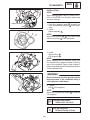
ESS00087
High altitude tuning
Use the chart in CHAPTER 8 to select main jets
according to variations in elevation and temperature.
NOTE:
These jetting specifications are subject to
change. Consult the latest technical information
from Yamaha to be sure you have the most upto-date jetting specifications.
1 Main jet
2 Pilot jet
3 Pilot screw
2-32
CARBURETOR TUNING
INSP
ADJ
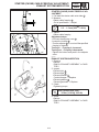
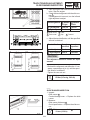
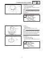
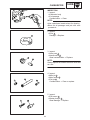
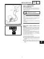
ESS00088
Guide for carburetion
2E301
1. Fuel flow chart:
A guide to the fuel flow rate according to the
throttle opening.
CAUTION:
If the air intake silencer and air chamber are
removed from the carburetors, the change
in pressure in the intake will create a lean
mixture that could result in severe engine
damage.
Removal of the air intake silencer and the air
chamber do not improve performance characteristics. They must be secured to the carburetor during tuning and adjustment, and
must always be in place when the engine is
operated. Examine the intake silencer and
air chamber regularly for cleanliness and
freedom from obstruction.
a High speed tuning range
b Mid-range speed tuning range
c Low speed tuning range
2-33
CARBURETOR TUNING
INSP
ADJ
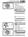
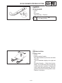
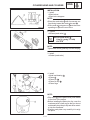
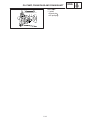
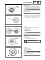
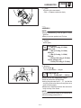
ESS00089
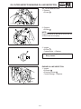
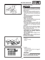
Low speed tuning
The carburetors are built so that low speed tuning can be done by adjusting the pilot screw 1
and throttle stop screw 2 .
CAUTION:
Never run the engine without the air intake
silencer installed. Severe engine damage
may result.
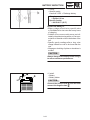
1. Tighten the pilot screw until it is lightly seated
and then back it out the specified number of
turns.
Pilot screw 1 :
1-1/4 turns out
Pilot screw effects:
Turn in
STD setting
Leaner
Mixture
Turn out
Richer
Mixture
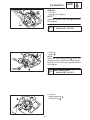
2. Set the engine idle speed by turning the
throttle stop screw 2 in (to increase engine
speed) or out (to decrease engine speed).
Standard idle speed:
1,200 ± 100 r/min
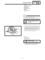
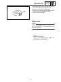
3. If low-speed performance is still poor at higher elevations under extreme conditions, the
standard pilot jets may need to be replaced.
In this way, the proper air/fuel mixture is obtained.
NOTE:
In this case, use a larger numbered pilot jet to
enrich the air/fuel mixture.
Standard pilot jet:
#90
2-34
CARBURETOR TUNING
INSP
ADJ
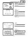
ESS00090
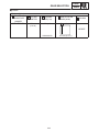
Main jet selection chart
Main jet selection chart
Spark plug color
Diagnosis
Remedy
Light tan or gray
Carburetors are
tuned properly.
Dry black or fluffy
deposits
Mixture is too rich.
Replace the main jet with the next smaller
size.
White or light gray
Mixture is too lean.
Replace the main jet with the next larger
size.
White or gray
insulator with small
black or grayish
brown spots and
electrodes having
a bluish-burnt
appearance
Mixture is too lean.
The piston is
damaged or seized.
Replace the piston and spark plug.
Tune the carburetors again. Begin with
low-speed tuning.
Melted electrodes
and possible a
blistered insulator
Metallic deposits on
insulator
Mixture is too lean.
The spark plug
melted.
Check the piston for holes or seizure.
Check the cooling system, gasoline octane
rating and ignition timing. After replacing
the spark plug with a colder type, tune the
carburetors again. Begin with low-speed
tuning.
2-35
CARBURETOR TUNING
INSP
ADJ
ESS00091
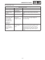
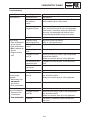
Troubleshooting
Trouble
Hard starting
Diagnosis
Adjustment
Insufficient fuel
Add gasoline.
Excessive use of
the starter or
choke
Return the starter lever to its seated position so
that the starter valve is fully closed.
Fuel passage is
clogged or frozen
S Check and, if necessary, clean the fuel tank air
vent, the fuel filter and all of the fuel passages.
S Check and, if necessary, clean the carburetor
air vents, fuel passages and the float valve.
S Clean the float chamber of any ice or water.
Overflow
Adjust the fuel level.
Improper idling
speed adjustment
Adjust the engine idle speed.
Refer to “Low speed tuning”.
Damaged pilot
screw
Replace the pilot screw.
Clogged bypass
hole
Clean the bypass hole.
Clogged or loose
pilot jet
S Remove the pilot jet, clean it with compressed
air and then install it.
S Make sure that the pilot jet is fully tightened.
Air leaking into the
carburetor joint
Retighten the clamp screws on the carburetor
joints.
Defective starter
valve seat
Clean or replace the starter valve seat.
Overflow
Adjust the fuel level.
Poor performance
at mid-range
speeds:
S Momentary slow
response
res
onse to
the throttle
S Poor acceleration
Clogged or loose
pilot jet
S Remove the pilot jet, clean it with compressed
air, and then install it.
S Make sure that the pilot jet is fully tightened.
Lean mixture
Overhaul the carburetors.
Poor performance
at normal speeds:
S Excessive fuel
consumption
S Poor acceleration
Clogged air vent
Remove the air vent hose and clean it.
Clogged or loose
main jet
S Remove the main jet, clean it with compressed
air, and then install it.
S Make sure that the main jet is fully tightened.
Overflow
Check and, if necessary, clean the float and
float valve.
Poor idling:
S Poor performance
at low speeds
S Poor acceleration
S Slow
Sl
response tto
throttle
S Engine tends to
stall
2-36
CARBURETOR TUNING
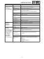
Trouble
Poor performance
at high speeds:
S Power loss
S Poor acceleration
Diagnosis
INSP
ADJ
Adjustment
Starter valve is left
open
Return the starter lever to its seated position so
that the starter valve is fully closed.
Clogged air vent
Remove and clean the air vent.
Clogged or loose
main air jet
S Remove the main jet, clean it with compressed
air, and then install it.
S Make sure that the main jet is fully tightened.
Clogged fuel line
Clean or replace the fuel line.
Dirty fuel tank
Clean the fuel tank.
Air leaks into the
fuel line
Tighten or replace the fuel line joint.
Low fuel pump
performance
Repair or replace the fuel pump.
Clogged fuel filter
Replace the fuel filter.
Clogged intake
Remove any obstructions (e.g., ice).
Abnormal
combustion:
S Backfiring
Lean mixture
Clean and adjust the carburetors.
Dirty carburetors
Clean the carburetors.
Dirty or clogged
fuel line
Clean or replace the fuel line.
Overflow:
S Poor idling
S Poor performance
at lo
low, mid
mid-range,
range
and high speeds
S Excessive fuel
consumption
S Hard starting
S Power loss
S Poor acceleration
Clogged air vent
Clean the air vent.
Clogged float
valve
S Disassemble and clean the float valve.
S Do not scratch the valve seat.
Scratched or
unevenly worn
float
valve or valve seat
S Clean or replace the float valve and valve seat.
S The valve seat and body must be replaced
as a set.
Broken float
Replace the float.
Incorrect float
level
Check and, if necessary, replace the following
parts:
S Float tang
S Float (entire assembly)
S Arm pin
2-37
CLUTCH
INSP
ADJ
ESS00092
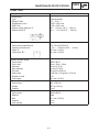
CLUTCH
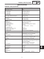
ESS00093
High altitude
Specifications
S
Silver
Y
Yellow
L
Blue
W
White
Model: VK540E
A ELEVATION
B Idle speed
C Clutch engarement
D Shift speed
E Gearing
F Primary spring
G Color
H Length
I Preload rate
J Wire diameter
K Outside diameter
L Weight (ID)
M Weight rivet
N Weight bushing
O Roller outer dia.
P Roller bushing
Q Pri. clutch shim
R Secondary spring
S Color
T Length
U Preload rate
V Wire diameter
W Outside diameter
X Sec. torque cam
Y Sec. clutch shim
1,000 m
( 3,500 ft)
APPROX. 1,200 r/min
APPROX. 2,600 r/min
APPROX. 6,700 r/min
17/39 (70 links)
90501-481J1
S-L-S
85.4 mm (3.36 in)
20 kg – 1.0 kg/mm
4.8 mm (0.19 in)
60 mm (2.36 in)
8AT
STEEL 13.3 mm
(0.52 in)
VESPEL
15.6 mm (0.61 in)
VESPEL
None
90508-50746
W
93.5 mm (3.68 in)
40_ (C-2)
721 kgmm/rad
5.0 mm (0.20 in)
65 mm (2.56 in)
37_
None
(STANDARD)
1,200 1,800 m
(3,000 6,500 ft)
z
APPROX. 2,800 r/min
z
z
90501-556G6
L
75.4 mm (2.97 in)
20 kgf – 2.0 kg/mm
5.5 mm (0.22 in)
z
z
STEEL 11.3 mm
(0.44 in)
z
z
z
z
z
z
z
1,800 m (6,500 ft )
z
APPROX. 3,000 r/min
z
z
90501-581J7
Y
z
25 kgf – 2.5 kg/mm
5.8 mm (0.23 in)
z
z
z
z
z
z
z
z
z
z
z
z
2-38
z
z
z
z
z
z
z
z
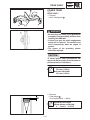
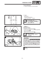
CLUTCH/GEAR SELECTION
INSP
ADJ
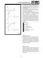
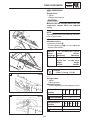
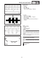
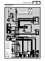
The clutch may require tuning depending upon
where the machine will be operated and the desired handling characteristics. The clutch can
be tuned by changing the engagement and
shifting speeds.
Clutch engagement speed is defined as the engine speed at which the machine first begins to
move from a complete stop.
Clutch shifting speed is defined as the engine
speed reached when the machine has travelled
200 300 m (650 1,000 ft) after being
started at full-throttle from a dead stop.
Normally, when a machine reaches shifting
speed, the vehicle speed increases but the engine speed remains nearly constant. Under unfavorable conditions (wet snow, icy snow, hills,
or rough terrain), however, engine speed may
decrease after the shifting speed has been
reached.
A Engine speed
B Good condition
C Bad condition
D Clutch shifting speed
E Clutch engagement speed
F Starting position
G 200 300 m (650 1,000 ft)
H Distance travelled
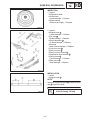
ESS00094
GEAR SELECTION
The reduction ratio of the driven gear to the
drive gear must be set according to the snow
conditions. If there are many rough surfaces or
unfavorable snow conditions, the drive/driven
gear ratio should be increased. If the surfaces
are fairly smooth or better snow conditions exist, decrease the ratio.
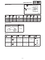
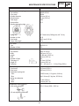
ESS00095
Gear ratio chart
The drive and driven gears and the chains
shown in the gear ratio chart are available as
options. The figures containing a decimal point
represent the drive/driven gear ratios, while the
bottom numbers designate the number of links
in the chain.
2-39
GEAR SELECTION
INSP
ADJ
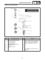
1 Chain and sprocket pat number
B Teeth & links
A Part name
C Part no.
D Standard
E Drive sprocket
17 teeth
83R-17682-00
VK540E
F Driven sprocket
39 teeth
83R-47548-00
VK540E
G Chain
70 links
94880-06070
VK540E
2 Gear ratio
A Drive gear
17 teeth
B Driven gear
39 teeth
2.29
70 links
3 Secondary spring
A
Part no.
B Spring rate
NSmm / rad
(kgSmm/rad)
90508-50746
7066 (721)
C Preload
N / m (kg / mm) (lb / in)
8.7 (0.89), 48.72
D Color
White
E Wire
gauge
mm (in)
F No. of
coils
5.0 (0.196)
4.74
G Free
length
mm (in)
93.5 (3.68)
H Outside
diameter
mm (in)
I Standard
65 (2.559)
VK540E
4 Secondary spring twist angle
90508-50746 (White)
A Seat
1
2
3
4
A
20_
50_
80_
110_
B
30_
60_
90_
120_
C
10_
40_ (STD)
70_
100_
B Sheave
5 Torque cam (secondary spring seat)
A Identification mark
B Part no.
C Cam angle
D Identification mark
E Standard
8AT-17684-00
37_
8AT00
VK540E
2-40
INSP
ADJ
GEAR SELECTION
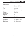
6 Primary spring
A Spring identification color code
B Spring rate color
C Preload color
D
Parts No.
E
F
H
I
Spring rate
N / mm
(kg / mm)
Preload
N
(kg)
Wire
gauge
mm (in)
Outside
diameter
mm (in)
G Color
K
J
No. of
coils
Free
length
mm (in)
L Standard
90501-481J1
9.8 (1.0)
196 (20)
Silver-Blue-Silver
4.8 (0.188)
60 (2.362)
5.16
85.4 (3.362)
90501-556G6
19.6 (2.0)
196 (20)
Blue
5.5 (0.216)
60 (2.362)
4.95
75.4 (2.969)
90501-581J7
24.5 (2.5)
245 (25)
Yellow
5.8 (0.228)
60 (2.362)
4.96
75.4 (2.969)
VK540E
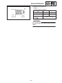
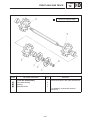
7 Clutch weights
A Standard
8AT-17605-00
44.0 g (1.55 oz)
VK540E
8 Rivets
A Part No.
B Material
C Length
mm (in)
D Weight
g (oz)
90261-06019
G Steel
13.3 (0.52)
3.1 (0.109)
90261-06017
H Steel
11.3 (0.44)
2.7 (0.095)
2-41
E Standard
VK540E
F Effects
I Increase
Force
J Decrease
Force
GEAR SELECTION
INSP
ADJ
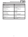
9 Rollers
I.D. 8 mm (0.3 in)
A ROLLER with
BUSHING PART
NUMBER
88R-17624-01
B OUTSIDE
DIAMETER
C BUSHING
TYPE (P / N)
D IDENTIFICATION
MARK (Width)
15.6 mm
(0.61 in)
Vespel
F No Mark
E Standard
VK540E
90380-08183
2-42
14.6 mm (0.57 in)
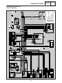
HIGH ALTITUDE TUNING
INSP
ADJ
ESS00096
HIGH ALTITUDE TUNING
To attain the best performance in high altitude conditions, carefully tune the snowmobile as outlined
below.
Check STD settings
S Carburetors
S Spark plugs
Adjust the main jet size according
to the chart
Test the main jet
(performance & plug color)
Adjust the size of the main jet
Not OK
OK
Re-test
OK
Not OK
Test the low-speed setting
Not OK
Check to see if the gearing is too high or low
OK
OK
Try high-altitude settings
Not OK
OK
Decide if the problem is with the
pilot jet and adjust accordingly
Not OK
OK
Check the engagement speed
and shift performance
Not OK
Adjust the primary clutch as
required
Not OK
OK
High altitude
tuning OK
OK
Not OK
Adjust the secondary clutch as
required
2-43
OK
INSP
ADJ
REAR SUSPENSION
ESS00100
REAR SUSPENSION
ESS00101
Stopper band
1. Adjust:
S Stopper band tension
CAUTION:
Make sure the left and right sides of the rear
suspension stopper band are adjusted
evenly.
NOTE:
This adjustment affects the handling characteristics of the machine.
Adjustment steps:
S Loosen the locknut 1 .
S Turn the adjusting nut 2 in or out to adjust the
stopper band tension.
Adjuster
thread
length a
25 ± 0.5 mm (0.98 ± 0.02 in)
Longer
Shorter
(Maximum)
(Minimum)
Effects
More weight
on skis; less
weight
transfer
Less weight
on skis; more
weight
transfer
S Tighten the locknut.
Locknut:
16 Nm (1.6 mSkg, 11 ftSlb)
A
ESS00102
Spring preload
1. Adjust:
S Spring preload
Adjustment steps:
S Turn the adjusting ring to the proper position.
B
Spring adjuster
position
1
Preload
Softer z
2
3
A Front Standard
Spring adjuster
position
Preload
B Rear Standard
2-44
4
5
! Harder
3
1
2
3
4
Softer z
5
6
7
! Harder
4
REAR SUSPENSION
INSP
ADJ
Extension spring preload
1. Adjust:
S Extension spring preload
Adjuster A
Preload
Turn in
Turn out
Harder
Softer
Snow Condition
Icy
Soft
Standard
Length B
16 mm (0
(0.63
63 in)
CAUTION:
Be sure the left and right spring preload is
same.
2-45
REAR SUSPENSION
INSP
ADJ
ESS00103
Rear suspension-full rate
1. Adjust:
S Full rate adjuster
Adjustment steps:
S Loosen the nut 1 1/2 or 3/4 turns, while holding the adjusting bolt 2 securely with a
wrench so it does not move.
CAUTION:
Never allow the adjusting bolt 2 to move
while loosening the nut.
S Turn the adjusting bolt 2 to the desired position.
Installation
position
Spring rate
and damping
Standard
A
B
C
Soft
Medium
Hard
A
NOTE:
S Be sure to make this adjustment when there is
no load (rider or cargo) on the snowmobile.
S Rotating the track will help to move the shock
absorber assembly.
CAUTION:
Be sure the adjusting bolt ends are set at the
same position on each side.
S While holding the adjusting bolt securely,
tighten the nut 1 .
Nut (full rate adjuster) 1 :
49 Nm (4.9 mSkg, 35 ftSlb)
CAUTION:
Never allow the adjusting bolt to move while
tightening the nut.
2-46
REAR SUSPENSION
INSP
ADJ
This model has a “Easy adjust” system for the
Full rate adjuster. The bolt has teeth on it. So
when the bolt is turned, it rides up and down the
bracket.
NOTE:
S The nut has to be loosen first, while the bolt is
held in place with a wrench.
S Then the bolt can be turned to adjust the shock
position up or down.
S If the bolt is turned with the nut tight, it is possible to strip the teeth off the bolt.
2-47
STEERING
CHAS
ESS00104
CHASSIS
ESS00105
STEERING
A :
15 Nm (1.5 mkg, 11 ftlb)
3
Order
Job name/Part name
Q’ty
Remove the parts in the order listed
below.
Handlebar removal
1
2
3
4
5
Remarks
1
1
2
1
1
Steering pad (rear)
Steering pad (front)
Handlebar holder (upper)
Handlebar
Handlebar holder (lower)
For installation, reverse the removal
procedure.
3-1
STEERING
CHAS
: 1 ESSO beacon 325 grease or
Aeroshell greaes #7A
A :
19 Nm (1.9 mkg, 14 ftlb)
B :
27 Nm (2.7 mkg, 20 ftlb)
C :
43 Nm (4.3 mkg, 31 ftlb)
D :
25 Nm (2.5 mkg, 18 ftlb)
Order
Job name/Part name
Q’ty
Removing the parts in the order listed
below.
Steering column and tie rod removal
1
2
3
4
5
6
7
Handlebar
Cotter pin
Relay rod
Tie rod
Lock washer
Bearing holder
Plane bearing
Steering column
Remarks
3
1
1
4
2
4
1
For installation, reverse the removal
procedure.
3-2
STEERING
CHAS
ESS00106
INSPECTION
1. Inspect:
Handlebar 1
Steering column 2
Bends/cracks/damage Replace.
WARNING
Do not attempt to straighten a bent column.
This may dangerously weaken the column.
2. Inspect:
Bearings (steering column) 1
Steering column 2 (bearing contact surfaces)
Scratches/wear/damage Replace.
3. Inspect:
Relay rod 1
Tie-rods 2
Bends/cracks/damage Replace.
WARNING
Do not attempt to straighten bent rods. This
may dangerously weaken the rods.
4. Check:
Rod end movement
Rod end freeplay exists Replace the rod
end.
Rod end turns roughly Replace the rod
end.
3-3
STEERING
CHAS
ESS00107
INSTALLATION
1. Install:
Tie-rod 1
Relay rod 2
NOTE:
Install the rod end 3 with the left-hand thread
onto the tie-rod on the right side.
The threads on both a rod ends must be the
same length.
CAUTION:
Always use new cotter pins.
Locknut (rod end):
25 Nm (2.5 mkg, 18 ftlb)
LOCTITE
Nut (suspension arm-tie-rod):
43 Nm (4.3 mkg, 31 ftlb)
2. Apply
Low temperature lithium soap base grease
(to bearing inner surface)
3. Tighten:
Bearing holder nut:
19 Nm (1.9 mkg, 14 ftlb)
Bearing holder bolt:
27 Nm (2.7 mkg, 20 ftlb)
Relay rod nut:
43 Nm (4.3 mkg, 31 ftlb)
CAUTION:
Always use a new lock washer and cotter
pin.
NOTE:
Bend the lock washer top along the bolts and
nuts flats.
3-4
STEERING
CHAS
4. Adjust:
Skis
Adjustment steps:
Temporarily install the handlebar.
Hold the handlebar straight and check that
the skis are at right angles to the handlebar.
Loosen the locknuts (relay rod) 1 .
Position the skis parallel in the riding direction.
With the skis in this position, turn the relay
rod 2 in either direction until the handlebars
at right angles with respect to the direction of
movement.
Turning the relay
rod in direction a
Turning the handlebar in direction c
Turning the relay
rod in direction b
Turning the handlebar in direction d
Tighten the locknuts (relay rod) 1 .
Locknut (relay rod):
25 Nm (2.5 mkg, 18 ftlb)
LOCTITE
5. Install:
Handlebar
CAUTION:
The upper handlebar holder should be
installed with the punch mark 1 forward.
Align the punch marks 2 with the handlebar holder gaps respectively.
Tighten the bolts to specification so that
the front clearance a is smaller than the
rear clearance b .
Bolt (handlebar holder):
15 Nm (1.5 mkg, 11 ftlb)
CAUTION:
First tighten the bolts on the front side of the
handlebar holder, and then tighten the bolts
on the rear side.
3-5
SKI
CHAS
ESS00108
SKI
A :
43 Nm (4.3 mkg, 31 ftlb)
B :
21 Nm (2.1 mkg, 15 ftlb)
: 1 ESSO beacon 325 grease or
Aeroshell greaes #7A
C : Fit the stopper with its raised portion positioned in front.
D : Be careful not to reverse the mounting positions of the left and right ski assemblies.
Order
1
2
3
4
5
Job name/Part name
Q’ty
Remarks
Remove the parts in the order listed below.
Ski removal
Cotter pin
Ski stopper
Collar
Ski
Ski runner
1
1
1
1
1
For installation, reverse the removal
procedure.
3-6
SKI
CHAS
ESS00109
INSPECTION
1. Inspect:
Ski 1
Ski runner 2
Ski stopper 3
Wear/cracks/damage Replace.
Mounting bolt 4
Collar 5
Wear/damage Replace.
3-7
FRONT SUSPENSION
CHAS
ESS00111
FRONT SUSPENSION
A :
43 Nm (4.3 mkg, 31 ftlb)
B :
21 Nm (2.1 mkg, 15 ftlb)
C :
2 Nm (0.2 mkg, 1.4 ftlb)
D :
16 Nm (1.6 mkg, 11 ftlb)
E :
5 Nm (0.5 mkg, 3.6 ftlb)
F :
10 Nm (1.0 mkg, 7.2 ftlb)
: 1 ESSO beacon 325 grease or
Aeroshell greaes #7A
Order
1
2
3
4
5
6
7
8
9
10
11
Job name/Part name
Q’ty
Remarks
Remove the parts in the order listed below.
Refer to “SKI”.
Front suspension removal
SKI
Cotter pin
Front arm (lower)
Front arm (upper)
Flange nut
Set screw
Suspension bracket
Absorber holder
Spring
Shock absorber
Circlip
Suspension arm
3
1
1
2
1
1
1
1
1
1
1
Loosen.
Loosen.
For installation, reverse the removal
procedure.
3-8
FRONT SUSPENSION
CHAS
ESS00112
HANDLING NOTES
WARNING
This shock absorber contains highly compressed nitrogen gas. Befor handling the
shock absorber read and make sure that you
understand the following information. The
manufacturer cannot be held responsible
for property damage or personal injury that
may result from improper handlind.
Do not tamper or attempt to open the gas
chamber.
Do not subject the shock absorber to
flames or any other source of high heat.
This may cause the unit to explode due to
excessive gas pressure.
Do not deform or damage the gas chamber
in any way. Gas chamber damage will result in poor damping performance.
ESS00113
INSPECTION
1. Inspect:
Shock absorber 1
Oil leaks/bending/damage Replace.
2. Inspect:
Suspension brackets 1
Suspension arm 2
Front arms 3
Cracks/wear/damage Replace.
Bushings 4
Collars 5
Thrust washers 6
Wear/scratches/damage Replace.
3. Inspect:
Bump rubber 1
Wear/damage Replace.
Absorber holder 2
Cracks/bending/damage Replace.
3-9
FRONT SUSPENSION
CHAS
4. Inspect:
Spring
Wear/cracks/damage Replace.
5. Measure:
Spring free length a
Out of specification Replace.
Spring free length limit:
235.0 mm (9.25 in)
6. Inspect:
Oil seals
Damage Replace.
ESS00114
INSTALLATION
1. Lubricate:
Bushing (suspension support 1 )
Bushing (suspension arm 2 )
Oil seal lips 3
Recommended grease:
ESSO beacon 325 grease or
Aeroshell grease #7A
2. Install:
Suspension arm
CAUTION:
Always use a new circlip.
NOTE:
Install the suspension arm so the “L” mark is on
the left side and the “R” mark is on the right side.
3-10
FRONT SUSPENSION
CHAS
3. Tighten:
Suspension bracket nut:
43 Nm (4.3 mkg, 31 ftlb)
Set screw:
2 Nm (0.2 mkg, 1.4 ftlb)
LOCTITE
NOTE:
Install the suspension bracket so that the “L”
mark is on the left side and the “R” mark is on the
right side.
4. Tighten:
Absorber holder bolt:
10 Nm (1.0 mkg, 7.2 ftlb)
Shock absorber nut:
5 Nm (0.5 mkg, 3.6 ftlb)
Locknut (shock absorber):
16 Nm (1.6 mkg, 11 ftlb)
Front arm nut:
43 Nm (4.3 mkg, 31 ftlb)
NOTE:
Be sure to install the front arms so that the “UPPER” mark is located in the upper position and
the “LOWER” mark is in the lower position.
CAUTION:
Always use a new cotter pin.
3-11
PRIMARY SHEAVE AND DRIVE V-BELT
POWR
TR
ESS00117
POWER TRAIN
ESS00118
PRIMARY SHEAVE AND DRIVE V-BELT
A : 1st 120 Nm (12.0 mkg, 85 ftlb)
2nd 60 Nm (6.0 mkg, 43 ftlb)
Order
1
2
3
Job name/Part name
Q’ty
Primary sheave removal
V-belt
Blind cap
Primary sheave assembly
Remarks
Remove the parts in the order listed below.
1
1
1
For installation, reverse the removal
procedure.
4-1
PRIMARY SHEAVE AND DRIVE V-BELT
A :
6 Nm (0.6 mkg, 4.3 ftlb)
B :
14 Nm (1.4 mkg, 10 ftlb)
C :
200 Nm (20 mkg, 145 ftlb)
POWR
TR
4
D : Clean the threads.
Apply LOCTITE #648 as illustrated in E .
And then tighten the spider. (The spider must
be turned counterclockwise to be tightened.)
Order
1
2
3
4
5
6
7
8
9
10
11
12
13
14
Job name/Part name
a 16 mm (0.63 in)
b 30 35 mm
(1.18 1.38 in)
Q’ty
Remarks
Remove the parts in the order listed below.
Primary sheave disassembly
Primary sheave cap
Primary sheave spring
Collar
Roller
Washer
Collar
Weight
Washer
Fixed sheave
Stopper
Sliding sheave
Bushing
Spider
Slider
1
1
3
3
6
3
3
6
1
1
1
1
1
6
For assembly, reverse the disassembly
procedure.
4-2
PRIMARY SHEAVE AND DRIVE V-BELT
POWR
TR
ESS00119
REMOVAL
1. Remove:
Drive V-belt guard
Drive V-belt
Grommet 1
2. Remove:
Primary sheave assembly 1
NOTE:
Use the primary sheave holder 2 and primary
sheave puller 3 .
Primary sheave holder:
90890-01701, YS-01880
Primary sheave puller:
YS-01881-1, YS-01882-1
4-3
PRIMARY SHEAVE AND DRIVE V-BELT
POWR
TR
ESS00120
DISASSEMBLY
1. Remove:
D Fixed sheave 1
D Stopper 2
D Sliding sheave 3
D Bushing 4
D Spider 5
Removal steps:
D Immerse the primary sheave assembly in 80_
100_C (176_ 212_F) water for several
minutes.
D Attach the lower piece of the clutch spider separator 6 onto a rigid table using suitable
mounting bolts.
Then, install the clutch separator adapter 7
onto the separator.
Clutch spider separator:
90890-01711, YS-28890-B
Clutch separator adapter:
90890-01740, YS-34480
D Fit the primary sheave assembly onto the
adapter and secure the supporting plates 8 .
NOTE:
Securely fit the projections on the adapter into
the fixed sheave holes.
D Set the clutch spider separator (bar wrench)
9 onto the spider and turn the special tool
clockwise to loosen the spider.
Clutch spider separator
(bar wrench):
90890-01711, YS-28890-B
CAUTION:
D The spider has a left-handed thread.
D Since a high torque is required to loosen
the spider, make sure that the spider, fixed
sheave and special tool are well secured.
Loosen the spider carefully to prevent
cracks and damage to the sheaves and spider.
D Remove the fixed sheave, fixed sheave stopper, and sliding sheave from the spider.
4-4
PRIMARY SHEAVE AND DRIVE V-BELT
POWR
TR
ESS00121
INSPECTION
1. Inspect:
Spider 1
Sliding sheave 2
Fixed sheave 3
Primary sheave cap 4
Cracks/damage Replace.
2. Inspect:
Primary sheave spring 1
Cracks/damage Replace.
3. Measure:
Primary sheave spring free length a
Out of specification Replace the primary
sheave spring.
Primary sheave spring free length
a:
85.4 mm (3.36 in)
NOTE:
When changing the primary sheave springs, refer to “GEAR SELECTION” in CHAPTER 2.
A
4. Measure:
Bushing-to-sheave clearance
Out of specification Replace bushing.
Use a feeler gauge 1
B
Bush clearance (primary sheave
cap) A :
0.25 mm (0.01 in)
Bush clearance (sliding sheave) B :
0.25 mm (0.01 in)
5. Measure:
Bushing inside diameter
Out of specification Replace.
Bushing inside diameter:
Primary sheave cap
New: 28.0 mm (1.10 in)
Wear limit: 28.2 mm (1.11 in)
Sliding sheave
New: 40.0 mm (1.57 in)
Wear limit: 40.2 mm (1.58 in)
4-5
PRIMARY SHEAVE AND DRIVE V-BELT
POWR
TR
6. Inspect:
Weight 1
Roller 2
Bushing 3
Slider 4
Rivet 5
Collar
Wear/scratches/damage Replace.
Slider inside clearance A1 +
Min. 0 mm (0 in)
Max. 0.3 mm (0.0118 in)
A
A2 :
Rivet replacement steps:
Remove old rivet with the appropriate drill.
Insert the rivet 1 from the ID mark 2 side.
Press or peen the rivet head so that the diameter a of the rivet head measures 8.5 mm (0.33
in) or larger.
7. Measure:
Bushing inside diameter
Out of specification Replace the bushings
as a set.
B
Bushing inside diameter:
A Roller
New: 8.0 mm (0.31 in)
Wear limit: 8.2 mm (0.32 in)
B Weight
New: 8.0 mm (0.31 in)
Wear limit: 8.2 mm (0.32 in)
NOTE:
When replacing the weight and roller bushings,
use the YXR clutch bushing jig kit.
,,,,,,
,,,,,,
,,,,,,
,,,,,,
,,,,,,
,,,,,,
,,,,,,
,,,,,,
,,,,,,
YXR clutch bushing jig kit:
YS-39752
C Removing
D Installing
4-6
PRIMARY SHEAVE AND DRIVE V-BELT
POWR
TR
ESS00122
ASSEMBLY
1. Install:
Sliding sheave (onto the spider)
NOTE:
Be sure the sliding sheave match mark (X) is
aligned with the spider match mark (X).
2. Install:
Fixed sheave (onto the spider)
NOTE:
Apply LOCTITE to the fixed sheave as shown.
CAUTION:
LOCTITE should be applied only to the
specified area. Never apply it to the bushings and other areas.
a 16 mm (0.63 in)
b 30 35 mm (1.18 1.38 in)
3. Install:
Fixed sheave stoppers 1
NOTE:
Stopper tapered portion should face fixed
sheave.
4. Tighten:
Spider
Tightening steps:
Finger-tighten the spider until it is stopped by
the fixed sheave stopper.
Hold the fixed sheave with the clutch spider
separator 1 .
Clutch spider separator:
90890-01711, YS-28890-B
NOTE:
Securely fit the projections on the clutch separator adapter 2 into the fixed sheave holes.
4-7
PRIMARY SHEAVE AND DRIVE V-BELT
POWR
TR
Tighten the spider to specification using the
clutch spider separator (bar wrench) 3 .
Spider:
200 Nm (20 mkg, 145 ftlb)
CAUTION:
The spider has a left-handed thread.
WARNING
Do not operate the primary sheave until
the LOCTITE has dried completely. Wait
24 hours before operating the primary
sheave.
Since a high torque is required to tighten
the spider, make sure the spider, fixed
sheave, and special tool are well secured.
Tighten the spider carefully to prevent
cracks and damage to the sheaves and spider.
5. Install:
Weight
Nut 1 :
6 Nm (0.6 mkg, 4.3 ftlb)
NOTE:
To maintain the primary sheave balance, the
bolts 2 must be installed with their threaded
portions pointing in a counterclockwise direction, as illustrated.
6. Install:
Primary sheave spring 1
Primary sheave cap 2
NOTE:
Be sure the sheave cap match mark (X) is
aligned with the spider match mark (X).
Be sure to use the flange bolts 3 to position a
to maintain the balance of primary sheave.
Primary sheave cap bolt:
14 Nm (1.4 mkg, 10 ftlb)
4-8
PRIMARY SHEAVE AND DRIVE V-BELT
POWR
TR
ESS00123
INSTALLATION
1. Install:
Primary sheave assembly
CAUTION:
Be sure to remove any oil or grease from the
tapered portion of the crankshaft and spider
using a cloth dampened with thinner.
2. Apply:
YAMALUBE 2-cycle oil or an equivalent
grease (to threads of primary sheave bolt)
3. Tighten:
Bolt (primary sheave) 1
Tightening steps:
Hold the primary sheave 3 using the primary
sheave holder 2 and tighten the bolt (primary
sheave) to specification.
Primary sheave holder:
90890-01701, YS-01880
Bolt (primary sheave) 1 :
(initial tightening)
120 Nm (12 mkg, 87 ftlb)
Loosen the bolt (primary sheave) completely.
Retighten the bolt (primary sheave) to specification.
Bolt (primary sheave) 1 :
60 Nm (6.0 mkg, 43 ftlb)
4. Adjust:
V-belt position
Refer to “DRIVE V-BELT” in CHAPTER 2.
Sheave distance
Sheave offset
Secondary sheave freeplay (clearance)
Refer to “SHEAVE DISTANCE AND OFFSET ADJUSTMENT” in CHAPTER 2.
4-9
SECONDARY SHEAVE
POWR
TR
ESS00124
SECONDARY SHEAVE
Order
Job name/Part name
Q’ty
A :
60 Nm (6.0 mkg, 43 ftlb)
B :
21 Nm (2.1 mkg, 15 ftlb)
Remarks
Remove the parts in the order listed below.
1
2
3
4
Secondary sheave removal
V-belt
Secondary shaft (jackshaft)
Washer
Shim
1
1
1
–
5
Secondary sheave assembly
1
With secondary sheave
Refer to “SHEAVE DISTANCE AND
OFFSET ADJUSTMENT” in CHAPTER 2.
For installation, reverse the removal
procedure.
4-10
SECONDARY SHEAVE
A
B
POWR
TR
Standard position:
No. 2
Standard twist angle:
40_
C
Standard position:
“C”
: 1 ESSO beacon 325 grease
or Aeroshell grease #7A
Order
1
2
3
4
5
6
7
Job name/Part name
Q’ty
Remarks
Remove the parts in the order listed below.
Secondary sheave disassembly
Circlip
Washer
Spring seat
Secondary spring
Sliding sheave
Shim
Fixed sheave
1
1
1
1
1
2
1
For assembly, reverse the removal
procedure.
4-11
SECONDARY SHEAVE
POWR
TR
ESS00125
DISASSEMBLY
WARNING
Use extreme CAUTION when disassembling the secondary sheave since serious
injury can occur due to the sudden release
of spring tension. Use the sheave compressor to contain the spring tension before removing the nuts (spring seat).
Do not attempt this procedure unless you
have the proper tools and understand the
instructions thoroughly.
1. Remove:
Circlip 1
Washer 2
4-12
SECONDARY SHEAVE
POWR
TR
ESS00126
INSPECTION
1. Inspect:
Sliding sheave 1
Fixed sheave 2
Spring seat 3
Shims 4
Cracks/damage Replace.
2. Inspect:
Bushing (spring seat) 1
Sliding sheave (V-belt contact surface) 2
Scratches/wear/damage Replace.
Sliding bushing 3
Unsymmetrical wear/damage Replace.
3. Inspect:
Secondary sheave spring 1
Cracks/damage Replace.
4. Measure:
Secondary sheave spring free length a
Below specification Replace the secondary sheave spring.
Free length limit a :
93.5 mm (3.68 in)
5. Measure:
Ramp shoe thickness a
Out of specification Replace the ramp
shoe.
Wear limit a :
1.0 mm (0.04 in)
4-13
SECONDARY SHEAVE
POWR
TR
ESS00127
ASSEMBLY
1. Install:
D Secondary sheave spring 1
D Spring seat 2
NOTE:
Hook the end of the secondary sheave spring
into the spring holes in the sliding sheave. Hook
the other end of the spring into the holes in the
spring seat.
Standard spring position:
C-2
Installation steps:
D Turn in the screw for the sheave compressor
so that the spring seat splines engage with the
fixed sheave splines.
NOTE:
Turn in this screw to a position where the spring
seat cam 1 does not come in to contact with the
sliding sheave cam 2 .
D Turn the sliding sheave through the specified
angle, in the counterclockwise direction.
D Holding the sliding sheave and fixed sheave in
this position.
Standard angle a :
40_
D Turn in the screw for the sheave compressor
so that the spring seat engages with the sliding
sheave.
D Install the washer and circlip in their proper
positions.
4-14
SECONDARY SHEAVE
POWR
TR
ESS00128
INSTALLATION
1. Lubricate:
Splines (fixed sheave)
Recommended grease:
Esso beacon 325 grease or
Aeroshell grease #7A
2. Tighten:
Secondary sheave bolt:
60 Nm (6.0 mkg, 43 ftlb)
3. Adjust:
V-belt position
Refer to “DRIVE V-BELT” in CHAPTER 2.
Sheave distance
Sheave offset
Secondary sheave freeplay (clearance)
Refer to “SHEAVE DISTANCE AND OFFSET ADJUSTMENT” in CHAPTER 2.
4-15
DRIVE CHAIN HOUSING
POWR
TR
ESS00132
DRIVE CHAIN HOUSING
Order
1
2
3
Job name/Part name
Q’ty
Drive chain housing removal
Brake caliper
Drain bolt
Bolt
Drive chain housing assembly
1
4
1
A :
10 Nm (1.0 mkg, 7.2 ftlb)
B :
21 Nm (2.1 mkg, 15 ftlb)
C :
10 Nm (1.0 mkg, 7.2 ftlb)
Remarks
Remove the parts in the order listed below.
Refer to “BRAKE”
Drain the oil
For installation, reverse the removal
proceudre.
4-16
DRIVE CHAIN HOUSING
Order
1
2
3
4
5
6
7
8
9
10
11
12
13
Job name/Part name
Q’ty
POWR
TR
A :
10 Nm (1.0 mkg, 7.2 ftlb)
B :
100 Nm (10.0 mkg, 72 ftlb)
Remarks
Remove the parts in the order listed below.
Drive chain housing disassembly
Shift link lever
Chain tensioner adjuster
Chain housing cover
Chain tensioner
Shift fork guide bar
Shift fork
Shift cam stopper
Shift cam
Counter axle
Idle axle
Driven sprocket
Drive chain
Drive axle
1
1
1
1
1
2
1
1
1
1
1
1
1
For assembly, reverse the removal
procedure.
4-17
DRIVE CHAIN HOUSING
POWR
TR
ESS00133
INSPECTION
1. Inspect:
Drive chain housing 1
Drive chain housing cover 2
Cracks/damage Replace.
Oil seals (drive chain housing)
Wear/damage Replace.
Bearings (drive chain housing and cover) 3
Pitting/damage Replace.
Bearing (chain tensioner) 4
Pitting/damage Replace the bearing and
the inner race holder as a set.
Replacement steps:
Remove the bearing(s) 3 using a general
bearing puller.
Install the new bearing(s).
NOTE:
Use a socket 5 that is the same size as the outside diameter of the race of the bearing race.
CAUTION:
Do not strike the inner race 6 or ball bearings 7 .
Contact only the outer race 8 .
Install a new circlip (drive chain housing).
CAUTION:
Always use new circlips.
2. Inspect:
Drive sprocket teeth 1
Driven sprocket teeth 2
Chain tensioner 3
Pitting/wear/damage Replace.
4-18
DRIVE CHAIN HOUSING
POWR
TR
3. Inspect:
Shift forks 1
On the gear and shift cam contact surfaces.
Wear/chafing/bends/damage Replace.
4. Check:
Shift fork movement
On its guide bar.
Unsmooth operation Replace fork and/or
guide bar.
5. Inspect:
Shift cam grooves 1
Wear/damage/scratches Replace.
Shift cam segment
Damage/wear Replace.
Stopper ball 2
Damage/wear Replace.
6. Inspect:
Gears
Damage/wear Replace.
7. Check:
Gear movement
Unsmooth operation Replace.
8. Inspect:
Mating dogs
Cracks/wear/damage Replace.
9. Inspect:
Splines
Damage Replace.
10. Inspect:
Drive select lever 1
Shift rod 2
Wear/damage Replace.
4-19
DRIVE CHAIN HOUSING
POWR
TR
11. Inspect:
Axle bearings
Shift cam bearing
Pitting/damage Replace.
12. Inspect:
Shift linkage levers 1
Spacer 2
Torsion spring 3
Wear/damage Replace.
13. Inspect:
Circlips
Washers
Damage/looseness/bends Replace.
4-20
DRIVE CHAIN HOUSING
POWR
TR
14. Measure:
14 link section a of the drive chain
Using a spring scale, pull on the drive chain
with 36 kg (80 lbs) of force b .
Out of specification Replace the drive
chain.
Maximum 14 link drive chain
section length a :
133.35 mm (5.25 in)
Limit 137.35 mm (5.41 in)
NOTE:
Measure the length between drive chain pin 1
and 15 as shown.
Perform this measurement at two or three different places.
If replacement is necessary, always replace the
chain and the sprockets as a set.
15. Inspect:
Drive chain 1
Stiffness Clean and lubricate or replace.
Drive chain plates 2
Damage/wear Replace the drive chain.
Cracks Replace the drive chain.
4-21
DRIVE CHAIN HOUSING
POWR
TR
ESS00134
INSTALLATION
1. During installation, pay attention to the following.
A Make sure that the bearing seals face towards
the drive chain as shown.
B1
B2 Be sure to install the spacers in their origi-
nal positions, otherwise the brake disc and
jackshaft will stick.
: ESSO beacon 325 grease or Aeroshell
grease #7A
2. Adjust:
Shift rod
Adjustment steps:
Move the shift lever to the “R” position.
Loosen the locknut 1 .
Turn the shift rod 2 in or out until the specified free play a is attained.
Free play a :
3 6 mm (0.12 0.24 in)
Be sure that the free play b between the
shift linkage lever and torsion spring is less
than 1 mm (0.04 in).
Tighten the locknut 1 .
3. Fill:
Drive chain housing oil
Refer to “DRIVE CHAIN” in CHAPTER 2.
4. Adjust:
Drive chain slack
Refer to “DRIVE CHAIN” in CHAPTER 2.
4-22
SECONDARY SHAFT (JACKSHAFT)
POWR
TR
ESS00135
SECONDARY SHAFT (JACKSHAFT)
Order
Job name/Part name
Q’ty
1
2
3
Secondary shaft (jackshaft) removal
V-belt
Secondary shaft (jackshaft)
Secondary sheave
1
1
1
A :
60 Nm (6.0 mkg, 43 ftlb)
B :
21 Nm (2.1 mkg, 15 ftlb)
Remarks
With secondary sheave
For installation, reverse the removal
procedure.
4-23
SECONDARY SHAFT (JACKSHAFT)
Order
1
2
3
4
5
Job name/Part name
Q’ty
POWR
TR
Remarks
Remove the parts in the order listed below.
Secondary shaft (jackshaft)
disassembly
Secondary sheave
Circlip
Bearing housing
Circlip
Bearing
Secondary shaft (jackshaft)
1
1
1
1
1
For assembly, reverse the removal
procedure.
4-24
SECONDARY SHAFT (JACKSHAFT)
POWR
TR
ESS00136
INSPECTION
1. Inspect:
Secondary shaft (jackshaft) 1
Scratches (excessive)/damage Replace.
Splines 2
Wear/damage Replace the jackshaft.
Bearing 3
Scratches/wear/damage Replace the
jackshaft.
INSTALLATION
1. Install:
Secondary sheave 1
Secondary sheave bolt 2 :
60 Nm (6.0 mkg, 43 ftlb)
2. Install:
Secondary shaft (jackshaft) assembly
Bolt (Secondary shaft (jackshaft)
assembly) 1 :
21 Nm (2.1 mkg, 15 ftlb)
3. Adjust:
Sheave distance
Sheave offset
Refer to “SHEAVE DISTANCE AND OFFSET ADJUSTMENT” in CHAPTER 2.
4-25
BRAKE
POWR
TR
ESS00138
BRAKE
A :
Order
1
2
3
Job name/Part name
Q’ty
Brake pad removal
Brake caliper assembly
Brake disc
Brake pads
48 Nm (4.8 mkg, 34.7 ftlb)
Remarks
Remove the parts in the order listed below.
1
1
2
For installation, reverse the removal
procedure.
4-26
BRAKE
POWR
TR
ESS00139
BRAKE PAD REPLACEMENT
1. Remove:
Brake caliper
NOTE:
Do not depress the brake lever when the caliper or disc is off the machine otherwise the
brake pads will be forced shut.
Replace the pads as a set if either one is found
to be worn to the wear limit a .
Wear limit a :
10 mm (0.39 in)
2. Measure:
Brake disc thickness a
Out of specification Replace the brake
disc.
Minimum thickness a :
3.5 mm (0.14 in)
Measuring point: 1 3 mm (0.04 0.12 in)
from the edge of the brake disc.
3. Install:
Brake pads
Brake caliper
Installation steps:
Removing the end cover 1 .
CAUTION:
Do not disassemble the torsion spring from
the end cover and the guide.
Removing the adjusting ratchet 1 .
4-27
BRAKE
POWR
TR
Screw in the adjusting screw 1 , and when it
contacts lightly with the end of the back up
plate, then back out the adjusting screw 1 1/2
to turn.
Fit the end of the adjusting ratchet 1 into the
adjusting screw 2 , and align the cut in the
guide 3 with the projection of the stationary
cover 4 , then install the guide 3 , which is
fitted to the end cover 5 twisting the end cover
clockwise approximately 30 degress and tighten the screws (end cover) 6 .
Screw (end cover) 6 :
2 Nm (0.2 mkg, 1.4 ftlb)
Installing the brake pads.
NOTE:
When installing the brake pad at the caliper
body side, make sure that projection a on the
brake pad are meshed with slot b on the caliper
body.
4. Tighten:
Brake caliper body bolt:
48 Nm (4.8 mkg, 34.7 ftlb)
5. Adjust:
Brake lever free play
4-28
BRAKE
A :
2 Nm (0.2 mkg, 1.4 ftlb)
B :
9 Nm (0.9 mkg, 6.5 ftlb)
POWR
TR
: 1 ESSO beacon 325 grease
or Aeroshell grease #7A
Order
1
2
3
4
5
6
Job name/Part name
Q’ty
Remarks
Remove the parts in the order listed below.
Brake caliper disassembly
Back up plate
End cover
Adjusting ratchet
Stationary cover
Lever
Adjusting screw
1
1
1
1
1
1
For assembly, reverse the removal
procedure.
4-29
BRAKE
POWR
TR
BRAKE CALIPER INSPECTION
1. Inspect:
One way lock 2 1
Stationary cover 2
Lever 3
Spiral gear 4 (lever)
Cracks/wear/damage Replace.
Replacement steps:
Remove the one way lock 2 1 using a thin flathead screw driver.
Remove the washer 2 and stationary cover
3.
Replace a damaged part(s) use a new one.
Reassemble the removed part(s) and reverse
the above steps.
CAUTION:
Always use a new one way lock 2.
2. Inspect:
Torsion spring 1
Fatigue/damage Replace end cover unit.
Inspection steps:
Check the fatigue of the torsion spring by the
projection mark a on the guide 1 located between the base marks b on the end cover 2 .
If projection mark a is not in the range between the base marks b , replace the end cover unit.
3. Inspect:
Adjusting ratchet 1
Cracks/wear/damage Replace.
Spring 2 (brake cable)
Fatigue/damage Replace.
Brake pad 3 thickness
Brake disc 4
Bend/cracks/damage Replace.
4-30
BRAKE
POWR
TR
INSTALLATION
1. Assemble:
Caliper body
Assemblage steps:
Lubricate the spiral gears 1 on the caliper
body and lever 2 with silicone grease.
Align the projection mark 1 on the lever with
the “86” mark 2 on the caliper body, screw the
lever 3 counterclockwise to the caliper body.
Install the stopper pin 1 into the holes on the
caliper body and stationary cover, then tighten
the bolts (stationary cover).
Bolt (stationary cover):
9 Nm (0.9 mkg, 6.5 ftlb)
Lubricate the one way locks 1 1 and 2 2 with
a lithium grease.
Lubricate the adjusting screw and back up
plate with a silicone grease.
Insert the back up plate 1 into the lever shaft
hole 2 .
4-31
BRAKE
POWR
TR
Screw in the adjusting screw 1 , and when it
contacts lightly with the end of the back up
plate, then back out the adjusting screw 1 1/2
to turn.
Fit the end of the adjusting ratchet 1 into the
adjusting screw 2 , and align the cut in the
guide 3 with the projection of the stationary
cover 4 , then install the guide 3 , which is
fitted to the end cover 5 twisting the end cover
clockwise approximately 30 degrees and tighten the screws (end cover) 6 .
Screw (end cover) 6 :
2 Nm (0.2 mkg, 1.4 ftlb)
2. Install:
Brake pads
NOTE:
When installing the brake pad at the caliper
body side, make sure that projection a on the
brake pad are meshed with slot b on the caliper
body.
3. Tighten:
Brake caliper body bolt 1 :
48 Nm (4.8 mkg, 34.7 ftlb)
4. Adjust:
Brake lever free play
4-32
SLIDE RAIL SUSPENSION
POWR
TR
SLIDE RAIL SUSPENSION
A :
Order
1
2
72 Nm (7.2 mkg, 52 ftlb)
Job name/Part name
Q’ty
Slide rail suspension removal
Tension adjuster
Blind cap
Slide rail suspension
Remarks
Remove the parts in the order listed below.
Loosen.
2
1
For installation, reverse the removal
procedure.
4-33
SLIDE RAIL SUSPENSION
POWR
TR
A :
4 Nm (0.4 mkg, 2.9 ftlb)
B :
16 Nm (1.6 mkg, 11 ftlb)
C :
49 Nm (4.9 mkg, 35 ftlb)
D :
72 Nm (7.2 mkg, 52 ftlb)
E :
30 Nm (3.0 mkg, 22 ftlb)
: 1 ESSO beacon 325 grease
or Aeroshell grease #7A
Order
1
2
3
4
5
6
7
8
9
10
11
Job name/Part name
Q’ty
Slide rail suspension disassembly
Stopper band
Hook
Bushing
Coller
Front shock abosrber
Bracket
Front suspension brakcet
Snspension wheel
Wheel bracket
Bushing
Front pivot arm
Remarks
Remove the parts in the order listed below.
2
2
4
2
1
2
1
2
2
2
1
4-34
SLIDE RAIL SUSPENSION
A :
72 Nm (7.2 mkg, 52 ftlb)
B :
49 Nm (4.9 mkg, 35 ftlb)
C :
24 Nm (2.4 mkg, 17 ftlb)
D :
80 Nm (8.0 mkg, 58 ftlb)
POWR
TR
: 1 ESSO beacon 325 grease
or Aeroshell grease #7A
Order
12
13
14
15
16
17
18
19
20
21
22
23
24
25
26
27
28
29
30
Job name/Part name
Q’ty
Spacer
Suspension wheel
Suspension wheel
Circlip
Bushing
Pull rod
Rear shock abosrber
Rear suspension bracket
Suspension wheel
Control rod
Bushing
Rear pivot arm bracket
Rear pivot arm
Coller
Cotter pin
Suspension wheel
Wheel base bolt
Coller
Sliding frame
1
2
2
2
2
2
1
1
2
2
2
1
1
1
2
2
1
1
2
4-35
Remarks
SLIDE RAIL SUSPENSION
A :
50 Nm (5.0 mkg, 36 ftlb)
B :
34 Nm (3.4 mkg, 25 ftlb)
C :
27 Nm (2.7 mkg, 20 ftlb)
D :
80 Nm (8.0 mkg, 58 ftlb)
POWR
TR
: 1 ESSO beacon 325 grease
or Aeroshell grease #7A
Order
31
32
33
34
35
36
37
38
39
40
Job name/Part name
Q’ty
Remarks
2
1
2
1
2
1
3
2
2
2
Pivot arm
Base bolt
Pivot shaft
Coller
Cotter pin
Rear axle
Guide wheel
Coller
Tension adjuster
Coller
For installation, reverse the removal
procedure.
4-36
SLIDE RAIL SUSPENSION
POWR
TR
ESS00148
INSPECTION
1. Inspect:
Suspension wheel
Guide wheel
Cracks/damage Replace.
Wheel bearing
Wheel turns roughly Replace.
2. Inspect:
Stopper band 1
Frayed/damage Replace.
Pull rods 2
Bends/damage Replace.
Shock absorbers 3
Oil leaks/damage Replace.
Bushings
Wear/cracks/damage Replace.
Front pivot arm 4
Rear pivot arm 5
Rear pivot arm bracket 6
Suspension wheel bracket 7
Sliding frame 8
Cracks/damage Replace.
Slide runner 9
Wear/damage Replace.
INSTALLATION
1. Install:
Stopper band 1
NOTE:
Install the stopper band with a toward the hook
and b toward the shaft.
Nut (stopper band):
4 Nm (0.4 mkg, 2.9 ftlb)
4-37
FRONT AXLE AND TRACK
POWR
TR
ESS00149
FRONT AXLE AND TRACK
Order
1
2
3
4
5
Job name/Part name
Q’ty
A :
21 Nm (2.1 mkg, 15 ftlb)
B :
85 Nm (8.5 mkg, 61 ftlb)
Remarks
Remove the parts in the order listed below.
Refer to “DRIVE CHAIN HOUSING”.
Refer to “SLIDE RAIL SUSPENSION”.
Refer to “SECONDARY SHEAVE”.
Front axle and track removal
Drive chain housing
Slide rail suspension
Secondary sheave
Speedometer gear assembly
Front axle housing
Bearing
Front axle assembly
Track
1
2
1
1
1
For installation, reverse the removal
procedure.
4-38
FRONT AXLE AND TRACK
A :
Order
1
2
3
Job name/Part name
Q’ty
Front axle disassembly
Front axle housing
Bearing
Sprocket wheel
POWR
TR
85 Nm (8.5 mkg, 61 ftlb)
Remarks
Remove the parts in the order listed below.
2
1
3
For assembly, reverse the removal
procedure.
4-39
FRONT AXLE AND TRACK
POWR
TR
ESS00150
INSPECTION
1. Inspect:
Track 1
Slide metal 2
Wear/cracks/damage Replace.
2. Inspect:
Sprocket wheel 1
Wear/break/damage Replace.
Front axle 2
Bends/scratches (excessive)/damage Replace.
ESS00151
INSTALLATION
1. Install:
Sprocket wheels
Guide wheels
NOTE:
When pressing the sprocket wheels onto the
front axle, align the lugs on each sprocket
wheel.
Position each sprocket wheel on the axle as
shown in the illustration.
2. Place the track in the chassis.
NOTE:
Be sure it is positioned as shown in the illustration.
A Turning direction
B Forward
4-40
EXHAUST ASSEMBLY
ENG
ESS00152
ENGINE
ESS00153
EXHAUST ASSEMBLY
A :
Order
1
2
3
4
5
Job name/Part name
Q’ty
30 Nm (3.0 mkg, 22 ftlb)
Remarks
Remove the parts in the order listed below.
Exhaust assembly removal
Spring 1
Spring 2
Spring 3
Exhaust assembly
Exhaust pipe joint
2
1
1
1
1
For installation, reverse the removal
procedure.
5-1
EXHAUST ASSEMBLY
ENG
ESS00154
INSPECTION
1. Inspect:
Exhaust joint 1
Exhaust pipe 2
Exhaust silencer 3
Cracks/damage Replace.
Exhaust gaskets 4
Exhaust gas leaks Replace.
5
5-2
ENGINE ASSEMBLY
ENG
ESS00156
ENGINE ASSEMBLY
A :
53 Nm (5.3 mkg, 38 ftlb)
B :
103 Nm (10.3 mkg, 74 ftlb)
Order
Job name/Part name
Q’ty
Remove the parts in the order listed below.
Refer to “EXHAUST ASSEMBLY”.
Refer to “CARBURETOR” in CHAPTER 6.
Refer to “RECOIL STARTER”.
Refer to “ENGINE COOLING FAN”.
Refer to “PRIMARY SHEAVE AND DRIVE
V-BELT” in CHAPTER 4.
Engine removal
Exhaust assembly
Carburetor
Recoil starter
Engine cooling fan
Primary sheave
1
2
3
4
5
Remarks
2
1
1
2
1
CDI magneto lead
Vacuum hose
Starter motor lead
Front engine bracket
Rear engine bracket
For installation, reverse the removal
procedure.
5-3
ENGINE ASSEMBLY
ENG
ESS00157
INSPECTION
1. Inspect:
Engine bracket (front) 1
Engine bracket (rear) 2
Cracks/damage Replace.
ESS00158
INSTALLATION
NOTE:
After installing all parts, refer to “CABLE ROUTING” in CHAPTER 8, to check the cable, lead
and hose routings.
1. Install:
Engine assembly 1
Front engine mount (left)
103 Nm (10.3 mkg, 74 ftlb)
Front engine mount (right)
53 Nm (5.3 mkg, 38 ftlb)
Rear engine mount
53 Nm (5.3 mkg, 38 ftlb)
NOTE:
Connect the oil hose to the oil pump when
installing the engine assembly.
2. Air bleed:
Oil pump
3. Adjust:
Sheave distance
Throttle cable
Oil pump cable
Starter cable
5-4
CYLINDER HEAD AND CYLINDER
ENG
ESS00159
CYLINDER HEAD AND CYLINDER
A :
20 Nm (2.0 mkg, 14 ftlb)
B : 1st 13 Nm (1.3 mkg, 9.4 ftlb)
2nd 25 Nm (2.5 mkg, 18 ftlb)
Order
Job name/Part name
Q’ty
1
2
3
4
5
6
7
8
9
10
Cylinder head and cylinder removal
Spark plug
Cylinder head
Cylinder head gasket
Cylinder
Cylinder gasket
Piston pin
Piston
Piston ring
Carburetor joint
Reed valve
2
2
2
2
1
2
2
4
1
2
C :
1 Nm (0.1 mkg, 0.7 ftlb)
D :
25 Nm (2.5 mkg, 18 ftlb)
E :
14 Nm (1.4 mkg, 10 ftlb)
Remarks
Remove the parts in the order listed below.
For installation, reverse the removal
procedure.
5-5
CYLINDER HEAD AND CYLINDER
ENG
ESS00160
REMOVAL
1. Remove:
Piston pin clips
Piston pins
Pistons
Small end bearings
NOTE:
Before removing the piston pin clip, cover the
crankcase with a clean rag so that you will not
accidentally drop the clip into the crankcase.
Before removing the piston pin, deburr the clip
groove and pin hole area. If the piston pin
groove is deburred and the piston pin is still difficult to remove, use the piston pin puller.
Put identification marks on each piston head
for reference during reinstallation.
Piston pin puller:
90890-01304, YU-01304
CAUTION:
Do not use a hammer to drive out the piston
pin out.
1 Piston pin
2 Piston
3 Piston pin puller
ESS00161
INSPECTION
1. Eliminate:
Carbon deposits
(from the combustion chamber)
Use the rounded scraper 1 .
CAUTION:
Do not use a sharp instrument. Avoid damaging or scratching the surface.
2. Measure:
Cylinder head warpage
Out of specification Resurface.
Warpage limit:
0.03 mm (0.0012 in)
Straight edge 1
Thickness gauge 2
5-6
CYLINDER HEAD AND CYLINDER
ENG
3. Eliminate:
Carbon deposits
(from the cylinders)
Use the rounded scraper 1 .
CAUTION:
Do not use a sharp instrument. Avoid damaging or scratching the surface.
4. Eliminate:
Carbon deposits
(from the piston crown and ring grooves)
5. Inspect:
Piston crown
Burrs/nicks/damage Replace.
6. Eliminate:
Score marks and lacquer deposits
(from the piston wall)
Use 600 800 grit wet sandpaper.
NOTE:
Sand in a crisscross pattern. Do not sand excessively.
7. Measure:
Piston-to-cylinder clearance
Measurement steps:
1st step:
Measure the cylinder bore (C) with a cylinder
bore gauge 1 .
NOTE:
Measure the cylinder bore (C) parallel to and at
right angles to the crankshaft. Then find the average of the measurements.
5-7
ENG
CYLINDER HEAD AND CYLINDER
Standard
Wear limit
Cylinder bore
(C)
73.00 73.02
mm
(2.874 2.875
in)
73.10 mm
(2.878 in)
Taper (T)
–
Out of round
(R)
–
0.05 mm
(0.002 in)
0.01 mm
(0.0004 in)
C = Maximum D
T = (Maximum of D1 or D2) –
(Maximum of D5 or D6)
R = (Maximum of D1, D3 or D5) –
(Minimum of D2, D4 or D6)
If out of specification, replace cylinder, and
replace piston and piston rings as a set.
2nd step:
Measure the piston skirt diameter (P) with a
micrometer.
a 10 mm (0.39 in) from the bottom edge of the piston
Piston size (standard) (P):
72.94 72.95 mm
(2.871 2.872 in)
If out of specification, replace the piston and
piston rings as a set.
3rd step:
Calculate the piston-to-cylinder clearance
with the following formula:
Piston-to-cylinder clearance =
Cylinder bore (C) –
Piston skirt diameter (P)
If out of specification, rebore or replace cylinder, and replace piston and piston rings as a
set.
Piston-to-cylinder clearance:
0.055 0.060 mm
(0.0022 0.0024 in)
Limit 0.1 mm (0.004 in)
5-8
CYLINDER HEAD AND CYLINDER
ENG
8. Measure:
Side clearance (piston rings)
Use the feeler gauge 1 .
Out of specification Replace the piston
and/or rings.
NOTE:
Eliminate the carbon deposits from the piston
ring grooves and rings before measuring the
side clearance.
Side clearance (top):
0.02 0.06 mm
(0.00079 0.0024 in)
Side clearance (2nd):
0.02 0.06 mm
(0.00079 0.0024 in)
9. Install:
Piston ring
(into the cylinder)
Push in the ring with the piston crown.
NOTE:
Insert the ring into the cylinder, and push it
approximately 20 mm (0.8 in) into the cylinder.
Push in the ring with the piston crown so that the
ring is at right angles to the cylinder bore.
10. Measure:
End gap (piston rings)
Use the feeler gauge 1 .
Out of specification Replace the rings as a
set.
End gap (top):
0.20 0.40 mm
(0.008 0.016 in)
End gap (2nd):
0.20 0.40 mm
(0.008 0.016 in)
a 20 mm (0.8 in)
5-9
CYLINDER HEAD AND CYLINDER
ENG
11. Measure:
Outside diameter (piston pin) a
Out of specification Replace the piston
pin.
a
Outside diameter (piston pin) a :
19.995 20.000 mm
(0.7872 0.7874 in)
12. Measure:
Piston pin-to-piston clearance
Out of specification Replace the piston.
Piston pin-to-piston clearance =
Bore size (piston pin) b –
Outside diameter (piston pin) a
b
Piston pin-to-piston clearance =
0.004 0.0065 mm
(0.00016 0.00026 in)
13. Inspect:
Reed valves 1
Bends/cracks/damage Replace.
14. Measure:
Valve stopper height a
Out of specification Replace the valve
stopper.
Valve stopper height a :
9.5 9.9 mm (0.37 0.39 in)
15. Measure:
Reed valve bending limit a
Out of specification Replace the reed
valve.
Reed valve bending limit a :
less than 0.6 mm (0.023 in)
5-10
CYLINDER HEAD AND CYLINDER
ENG
ESS00162
INSTALLATION
1. Install:
Reed valves
Reed valve stoppers
NOTE:
Place the reed valve 1 with its concave surface facing toward the reed valve seat 2 .
Fit the reed valve stopper cut a into the corresponding cut b on the reed valve.
2. Tighten:
Screws (reed valve) 1
Screws (reed valve) 1 :
1 Nm (0.1 mkg, 0.7 ftlb)
LOCTITE
NOTE:
Tighten each screw gradually to avoid warping.
3. Install:
Gasket (read valve)
4. Install:
Small end bearing 1
Piston 2
Piston pin 3
Piston pin clip 4
Piston rings
NOTE:
The arrow a on the piston must point toward
to the front of the engine.
Before installing the piston pin clip, cover the
crankcase with a clean rag so that you do not
accidentally drop the pin clip and other material into the crankcase.
Position each piston very carefully in its original place.
5-11
CYLINDER HEAD AND CYLINDER
ENG
CAUTION:
Always use new piston pin clips.
Do not allow the clip gap to align with the
piston pin slot.
5. Check:
Piston ring position
CAUTION:
Make sure that the ring ends are properly
fitted around the ring locating pins in the
piston grooves.
Be sure to check that the manufacturer’s
marks or numbers stamped on the rings
face upward.
6. Install:
Gasket (cylinder)
7. Install:
Cylinder
NOTE:
Install the cylinder with one hand while compressing the piston rings with the other hand.
8. Tighten:
Nuts (cylinder)
Nuts (cylinder):
25 Nm (2.5 mkg, 18 ftlb)
NOTE:
Tighten nuts in crisscross pattern.
5-12
CYLINDER HEAD AND CYLINDER
ENG
9. Install:
Gasket (cylinder head)
Cylinder heads
10. Tighten:
Nuts (cylinder head)
Tightening steps:
Temporarily tighten the cylinder head nuts
1 6 as follows.
1st step:
Tighten the nuts 1 6
Nut (cylinder head) 1 6 :
13 Nm (1.3 mkg, 9.4 ftlb)
2nd step:
Retighten the nuts 1 6
Nut (cylinder head) 1 6 :
25 Nm (2.5 mkg, 18.1 ftlb)
5-13
OIL PUMP, CRANKCASE AND CRANKSHAFT
ENG
ESS00167
OIL PUMP, CRANKCASE AND CRANKSHAFT
A : 1st 13 Nm (1.3 mkg, 9.4 ftlb)
2nd 21 Nm (2.1 mkg, 15 ftlb)
Order
Job name/Part name
Q’ty
1
2
3
4
5
6
7
8
Oil pump, crankcase and crankshaft
removal
Oil pump
Oil pump drive gear
Lower crank case
Crankshaft
Stopper ring
Oil seal
Oil seal
Upper crankcase
Remarks
Remove the parts in the order listed below.
1
1
1
1
1
1
1
1
For installation, reverse the removal
procedure.
5-14
OIL PUMP, CRANKCASE AND CRANKSHAFT
ENG
ESS00168
INSPECTION
1. Measure:
Runout
Use the V-blocks and a dial gauge.
Out of specification Replace or repair the
crankshaft.
Dial gauge:
90890-03097, YU-03097
Runout limit:
C1
: 0.03 mm (0.0012 in)
C2, C3: 0.04 mm (0.0016 in)
C4
: 0.05 mm (0.0020 in)
a 97 mm (3.82 in)
b 93 mm (3.66 in)
2. Measure:
Small end freeplay a
Use the dial gauge.
Out of specification Replace the defective
parts.
Small end freeplay a :
0.8 1.0 mm (0.03 0.04 in)
Big end side clearance b
Use the feeler gauge.
Out of specification Replace the defective
parts.
b
Big end side clearance b :
0.25 0.75 mm
(0.01 0.03 in)
3. Inspect:
Crankshaft bearings 1
Pitting/damage Replace.
Stopper ring 2
Bends/damage Replace.
Crankshaft oil seals 3
Wear/damage Replace.
CAUTION:
Lubricate the bearings immediately after examining them in order to prevent rust.
5-15
OIL PUMP, CRANKCASE AND CRANKSHAFT
ENG
4. Inspect:
Lower crankcase 1
Upper crankcase 2
Front left brackets 3
Front right brackets 4
Rear bracket 5
Dampers 6
Cracks/damage Replace.
5. Inspect:
Oil pump
Cracks/damage Replace.
Oil hoses
Clogs/damage Replace.
OIL PUMP STROKE ADJUSTMENT
1. Remove:
Oil pump cover 1
2. Wipe off the grease from the plunger top.
3. Measure:
Minimum pump stroke a
Out of specification Adjust.
Minimum pump stroke a :
0.20 0.25 mm
(0.008 0.010 in)
Minimum pump stroke measurement steps:
Turn the pump worm gear 1 with your fingers, until the plunger top 2 is at its maximum distance from the pump body mating
surface 3 of the pump cover.
Using a feeler gauge, measure the minimum
pump stroke a between the adjusting plate
4 and the raised boss 5 on the adjusting
pulley.
If minimum pump stroke is not with in the
specified limits, perform the adjustment
steps.
5-16
OIL PUMP, CRANKCASE AND CRANKSHAFT
ENG
4. Measure:
Maximum pump stroke b
Out of specification Adjust.
Maximum pump stroke b :
1.65 1.87 mm
(0.065 0.074 in)
Maximum pump stroke measurement steps:
Pull the oil pump cable 1 out of its sheath as
far as it will go. The cable must be held in this
taut position when measuring the maximum
pump stroke.
NOTE:
It may be helpful to securely wrap duct tape 2
around the cable where it enters the sheath.
Turn the pump worm gear 3 with your fingers, until the plunger top 4 is at its maximum distance from the pump body 5 .
Using a feeler gauge, measure the maximum pump stroke b .
If maximum pump stroke is not with in the
specified limits, perform the adjustment
steps.
5. Adjust:
Oil pump stroke
Adjustment steps:
Remove the locknut 1 , spring washer 2
and adjusting plate 3 .
Adjust the pump stroke by adding or removing a shim.
4 Shims
Add shim Pump stroke is increased.
Remove shim Pump stroke is decreased.
Reinstall the adjusting plate, spring washer
and locknut.
Locknut 1 :
7 Nm (0.7 mkg, 5.1 ftlb)
Recheck the minimum and maximum pump
stroke.
If out of specification limits, perform the
above steps again.
5-17
OIL PUMP, CRANKCASE AND CRANKSHAFT
ENG
ESS00169
INSTALLATION
1. Install:
Stopper rings 1
(onto the lower crankcase bearing as shown)
2 Knock pin
A Lower crankcase
B Upper crankcase
2. Install:
Crankshaft assembly
(to upper crankcase)
NOTE:
Set the knock pins 1 on the upper crankcase
and labyrinth seal into the pin holes 2 of the
bearings and upper crankcase by turning the
bearings and labyrinth seal. At the same time,
align the bearing punched marks 3 with the
crankcase mating surface 4 .
CAUTION:
The oil seal lip must fit into the crankcase
groove.
CAUTION:
Before installing and torquing the crankcase bolts, be sure to check that the crankshaft turns smoothly.
3. Tighten:
Crankcase bolts 1 10 (M8)
NOTE:
Tighten the bolts in order, starting with the lowest number, and torque the bolts in two stages.
Bolt (crankcase) 1 10 :
First:
13 Nm (1.3 mkg, 9.4 ftlb)
Final:
21 Nm (2.1 mkg, 15 ftlb)
5-18
OIL PUMP, CRANKCASE AND CRANKSHAFT
OIL PUMP
1. Install
Dowel pins
Oil pump 1
5-19
ENG
CDI MAGNETO
ENG
ESS00170
CDI MAGNETO
A :
Order
1
2
3
4
5
6
Job name/Part name
Q’ty
85 Nm (8.5 mkg, 61 ftlb)
Remarks
Remove the parts in the order listed below.
CDI magneto removal
Rotor
Stator assembly
Charge coil
Lighting coil 1
Lighting coil 2
Pulser coil
1
1
1
1
1
1
For installation, reverse the removal
procedure.
5-20
CDI MAGNETO
ENG
ESS00171
REMOVAL
1. Remove:
Nut 1 (CDI magneto)
NOTE:
Attach the universal rotor holder 2 to hold the
CDI magneto.
Universal rotor holder:
90890-01235, YU-01235
2. Remove:
Rotor 1
NOTE:
Attach the rotor holding puller 2 to the CDI
magneto and fully tighten the tool holding bolts,
but make sure the tool body is parallel with the
CDI magneto.
Rotor holding puller:
90890-01362, YU-33270
3. Remove:
Stator assembly 1
Woodruff key 2
5-21
CDI MAGNETO
ENG
ESS00172
INSTALLATION
NOTE:
After installing all parts, refer to “CABLE ROUTING” in CHAPTER 8, to check the cable, lead
and hose routings.
1. Pass the magneto leads 1 throught the
hole, and install the grommet 2 to the crankcase.
2. Install:
S Stator assembly 3
NOTE:
Align the timing mark (") 4 on the stator plate
with the seam line 5 of the crankcase.
3. Install:
S Woodruff key 1
S CDI magneto 2
NOTE:
When installing the CDI magneto, make sure
the woodruff key is properly seated in the key
way of the crankshaft. Apply a light coating of
lighium soap base grease to the tapered portion
of the crankshaft end.
CAUTION:
Be sure to remove any oil or grease from the
tapered portion of the crankshaft using a
cloth dampened with thinner.
4. Tighten:
S Nut 1 (CDI magneto)
NOTE:
Attach the universal rotor holder 2 to hold the
CDI magneto.
Universal rotor holder:
90890-01235, YU-01235
Nut (CDI magneto):
85 Nm (8.5 mSkg, 61 ftSlb)
5-22
ENGINE COOLING FAN
ENG
ESS00173
ENGINE COOLING FAN
A :
Order
Job name/Part name
Q’ty
43 Nm (4.3 mkg, 3.1 ftlb)
Remarks
Removing the parts in the order listed
below.
Engine cooling fan removal
1
2
3
Cooling fan cover
Fan belt driven pulley
Shim
1
2
–
4
5
6
7
Fan belt
Fan belt drive pulley
Cooling fan housing
Cooling fan
1
1
1
1
Refer to “COOLING FAN BELT TENSION
ADJUSTMENT” in CHAPTER 2.
For installation, reverse the removal
procedure.
5-23
ENGINE COOLING FAN
ENG
ESS00174
REMOVAL
1. Remove:
Cylinder air shroud 1
Seal rubber stay 2 (air duct)
Cooling fan cover 3
2. Remove:
Recoil starter 1
3. Remove:
Starter pulley 1
Fan belt drive pulley 3
Fan belt 4
NOTE:
Attach the universal rotor holder 2 to hold the
starter pulley.
Universal rotor holder:
90890-01235, YU-01235
4. Remove:
Engine mounting bracket 1
Starter motor 2
Cooling fan housing 3
Seal rubber 4
5-24
ENGINE COOLING FAN
ENG
ESS00175
INSPECTION
1. Inspect:
Upper air shroud 1
Cracks/damage Replace.
2. Inspect:
Cooling fan grill 1
Cooling fan housing 2
Cracks/damage Replace.
3. Inspect:
Cooling fan belt 1
Wear/cracks/damage Replace.
4. Inspect:
Cooling fan 1
Cracks/damage Replace.
Bearings (cooling fan housing) 2
Pitting/damage Replace.
Replacement steps:
Remove the bearing(s) 2 using a general
bearing puller.
Install the new bearing(s).
NOTE:
Use a socket 3 that is the same size as the outside diameter of the race of the bearing race.
CAUTION:
Do not strike the inner race 4 or ball bearings 5 . Contact only the outer race 6 .
5-25
ENGINE COOLING FAN
ENG
ESS00176
INSTALLATION
1. Install:
Seal rubber 1
Cooling fan housing 2
Engine mounting bracket 3
Starter motor 4
2. Install:
Fan belt 1
Fan belt drive pulley 2
Starter pulley 3
NOTE:
Attach the universal rotor holder 4 to hold the
starter pulley.
Universal rotor holder:
90890-01235, YU-01235
3. Measure:
Cooling fan belt deflection.
Out of specification Adjust.
Refer to “COOLING FAN BELT INSPECTION” in CHAPTER 2.
Cooling fan belt deflection:
8 mm (0.31 in.)/4 6 kg
(8.8 13.2 lb)
4. Install:
Recoil starter 1
5. Install:
Cooling fan cover 1
Seal rubber stay (air duct) 2
Cylinder air shroud 3
5-26
RECOIL STARTER
ENG
ESS00177
RECOIL STARTER
A :
10 Nm (1.0 mkg, 7.2 ftlb)
B :
23 Nm (2.3 mkg, 17 ftlb)
Order
1
2
3
4
5
6
7
8
9
Job name/Part name
Q’ty
Remarks
Remove the parts in the order listed below.
Refer to “EXHAUST ASSEMBLY”.
Recoil starter removal
Exhaust assembly
Recoil starter assembly
Nut
Special washer
Drive plate
Spring seat
Spring
Drive pawl
Sheave drum
Starter spring
1
1
1
1
1
1
1
1
1
For installation, reverse the removal
procedure.
5-27
RECOIL STARTER
ENG
ESS00178
REMOVAL
1. Remove:
Starter handle 1
Ground lead 2
NOTE:
To remove the starter handle, untie the knot 3
in the starter rope and then re-tie a knot 4 in the
rope end so that it is not pulled into the recoil
starter case 5 .
ESS00179
INSPECTION
1. Inspect:
Drive plate 1
Cracks/bends/damage Replace.
Spring 2 (drive plate)
Wear/damage Replace.
Starter rope 3
Wear/breaks/damage Replace.
Starter spring 4
Cracks/bends/damage Replace.
Sheave drum 5
Cracks/damage Replace.
Drive pawl 6
Return spring 7
Wear/cracks/damage Replace.
5-28
RECOIL STARTER
ENG
ESS00180
INSTALLATION
1. Hook the starter spring around the post in the
starter case. Carefully wind the spring counterclockwise, and fit the spring into the case.
NOTE:
After installing the spring thoroughly apply lowtemperature grease.
2. Pass the starter rope end into the sheave
drum, and knot the rope end. Then fit the
knot into the cutout in the sheave drum.
3. Wind:
Starter rope (2 turns counterclockwise)
(to sheave drum)
4. Install:
Sheave drum
(into starter case)
NOTE:
Be sure the inner hook on the starter spring
hooks around the post on the sheave drum.
5. Apply:
Grease (lightly)
(to pivot point of the drive pawl)
Low-temperature grease
6. Install:
Drive pawl 1
Return spring 2
NOTE:
Hook the return spring end to the drive pawl 1 .
Then, hook other end of the return spring to the
post 3 on the sheave drum.
5-29
RECOIL STARTER
ENG
7. Install:
Spring (drive plate)
Spring seat
Drive plate
Special washer
Washer
Spring washer
Nut
NOTE:
Be sure the cutout portion in the drive plate fits
over the post on the drive pawl.
Nut (drive plate):
10 Nm (1.0 mkg, 7.2 ftlb)
LOCTITE
8. Pull about four inches of starter rope from out
of the cutout portion in the sheave drum, and
rotate the sheave drum five times counterclockwise to preload the starter spring.
Then knot the rope end so that it will not be
pulled into the recoil starter case.
9. Install:
Recoil starter
Starter handle
Bolt (recoil starter):
10 Nm (1.0 mkg, 7.2 ftlb)
10. Check the starter for smooth operation. If it
does not operate smoothly, repair it.
5-30
CARBURETOR
CARB
ESS00197
CARBURETION
ESS00198
CARBURETOR
Order
1
2
3
4
5
6
Job name/Part name
Q’ty
Remarks
Remove the parts in the order listed below.
Carburetor removal
T.O.R.S. lead
Starter cable
Throttle cable
Oil pump cable
Fuel hose
Clamp
1
1
1
1
1
2
For installation, reverse the removal
procedure.
6-1
CARBURETOR
A :
3 Nm (0.3 mkg, 2.2 ftlb)
B :
2 Nm (0.2 mkg, 1.4 ftlb)
C :
0.8 Nm (0.08 mkg, 0.58 ftlb)
D :
5 Nm (0.5 mkg, 3.6 ftlb)
E :
9 Nm (0.9 mkg, 6.5 ftlb)
F :
3.5 Nm (0.35 mkg, 2.53 ftlb)
Order
1
2
3
4
5
6
7
8
Job name/Part name
Q’ty
CARB
Remarks
Remove the parts in the order listed below.
Carburetor disassembly
Throttle switch
Starter plunger
Float chamber cover
Float
Valve seat assembly
Pilot jet
Main nozzle
Main jet
1
1
1
1
1
1
1
1
For assembly, reverse the removal
procedure.
6-2
6
CARBURETOR
CARB
ESS00201
INSPECTION
1. Inspect:
Carburetor body
Fuel passage
Contamination Clean.
NOTE:
Use a petroleum based solvent for cleaning.
Blow out all passages and jets with compressed air.
2. Inspect:
Float 1
Damage Replace.
3. Inspect:
Valve seat 1
Needle valve 2
Wear/contamination Replace.
NOTE:
Always replace the needle valve and valve seat
as a set.
4. Inspect:
Main jet 1
Main nozzle 2
Pilot jet 3
Contamination Clean or replace.
5. Inspect:
Pilot screw 1
Starter plunger 2
Wear/damage Replace.
6-3
CARBURETOR
CARB
6. Check:
Throttle valve movement
Stick Replace carburetor body.
ESS00202
ASSEMBLY
NOTE:
Before reassembling, wash all parts in clean
gasoline.
Always use new gaskets and O-rings.
1. Tighten:
Inner parts
Main nozzle:
3 Nm (0.3 mkg, 2.2 ftlb)
Valve seat:
5 Nm (0.5 mkg, 3.6 ftlb)
Main jet:
2 Nm (0.2 mkg, 1.4 ftlb)
Pilot jet:
0.8 Nm (0.08 mkg, 0.58 ftlb)
Starter plunger cap:
3.5 Nm (0.35 mkg, 2.53 ftlb)
2. Measure:
Float height a
Out of specification Adjust.
Float height a :
12 16 mm (0.47 0.63 in)
Measurement and adjustment steps:
Hold the carburetor upside down.
Incline the carburetor at 60 70 (so that the
end of the float valve does not hang down as a
result of float weight).
Measure the distance between the carburetor
body and top of the floats.
NOTE:
The float arm should resting on the needle valve
without exerting pressure on it.
6-4
CARBURETOR
CARB
If the float height is not within specification, inspect the valve seat and needle valve.
If either is worn, replace them both.
If both are fine, adjust the float height by bending the float arm tang 1 on the float.
Recheck the float height.
ESS00204
INSTALLATION
NOTE:
After installing all parts, refer to “CABLE ROUTING” in CHAPTER 8, to check the cable, lead
and hose routings.
1. Adjust:
Starter cable freeplay
Refer to “STARTER (CHOKE) CABLE ADJUSTMENT” in CHAPTER 2.
6-5
FUEL PUMP
CARB
ESS00206
FUEL PUMP
Order
1
2
3
4
Job name/Part name
Q’ty
Remarks
Remove the parts in the order listed below.
Fuel pump removal
Fuel hose
Fuel delivery hose
Vacuum hose
Fuel pump assembly
1
1
1
1
For installation, reverse the removal
procedure.
6-6
FUEL PUMP
CARB
ESS00207
INSPECTION
1. Inspect:
Fuel hose 1
Fuel delivery hoses 2
Vacuum hose 3
Clogs/damage Replace.
2. Check:
Fuel pump operation
Checking steps:
Connect the Mity vac 1 to the pulser hose 2 .
Mity vac:
90890-06756, YB-35956
Place a container 3 under the end of the fuel
delivery hoses 4 .
Operate the Mity vac 1 while checking that
fuel flows from the fuel delivery hoses 4 .
If fuel does not flow out, replace the fuel pump.
ESS00208
INSTALLATION
NOTE:
After installing all parts, refer to “CABLE ROUTING” in CHAPTER 8, to check the cable, lead
and hose routings.
1. Bleed:
Oil system
Refer to “OIL PUMP” in CHAPTER 2.
6-7
SWITCH INSPECTION
ELEC
ELECTRICAL
SWITCH INSPECTION
SWITCH INSPECTION
Use a pocket tester to check the terminals for
continuity. If the continuity is faulty at any point,
replace the switch.
Pocket tester:
90890-03112, YU-03112
NOTE:
Set the pocket tester to “0” before starting a
test.
When testing the switch for continuity the
pocket tester should be set to the “ 1” Ω
range.
When checking the switch turn it on and off a
few times.
INSPECTING A SWITCH SHOWN IN THE
MANUAL
The terminal connections for switches (main
switch, handlebar switch, engine stop switch,
light switch, etc.) are shown in a chart similar to
the one on the left.
This chart shows the switch positions in the column and the switch lead colors in the top row.
For each switch position, “
” indicates
the terminals with continuity.
The example chart shows that:
1 There is continuity between the “Blue/Yellow
and Blue/Black” leads when the switch is set
to “OFF”.
2 There is continuity between the “Red and
Brown/Blue” leads when the switch is set to
“ON”.
7-1
7
19 CDI unit
16 Spark plug
17 Ignition coil
10 Main switch
23 Throttle switch
24 Carburetor switch
20 CDI magneto
22 Engine stop switch
IGNITION SYSTEM
IGNITION SYSTEM
CIRCUIT DIAGRAM
7-2
ELEC
IGNITION SYSTEM
ELEC
TROUBLESHOOTING
NO SPARK OR WEAK SPARK.
Check the spark plug gap.
OK
OUT OF SPECIFICATION
Repair or replace the spark plug.
Check the spark plug cap resistance.
OK
OUT OF SPECIFICATION
Replace the spark plug cap.
Check the ignition coil resistance.
OK
OUT OF SPECIFICATION
Replace the ignition coil.
Check the source coil.
OK
FAULTY
Replace the source coil.
Check the engine stop switch,
throttle switch, carburetor switch
and main switch.
OK
FAULTY
Replace the handlebar switch (right), carburetor
switch, and/or main switch.
Correct connection and/or replace
CDI unit and/or Rectifier/regulator.
7-3
IGNITION SYSTEM
ELEC
SPARK PLUG CAP
1. Remove:
D Spark plug cap
2. Connect:
D Pocket tester
(to the spark plug cap)
3. Measure:
D Spark plug cap resistance
Out of specification Replace.
Spark plug cap resistance:
5 kΩ at 20_C (68_F)
IGNITION COIL
1. Disconnect:
D Ignition coil lead
D Spark plug lead
2. Connect:
D Pocket tester
(to the ignition coil and spark plug lead)
3. Measure:
D Primary coil resistance 1
D Secondary coil resistance 2
Out of specification Replace.
Primary coil resistance 1 :
0.2 Ω ± 20% at 20_C (68_F)
Secondary coil resistance 2 :
4.9 kΩ ± 20% at 20_C (68_F)
SOURCE COIL/PULSER COIL
1. Disconnect:
D CDI magneto coupler
2. Connect:
D Pocket tester
(to CDI magneto coupler)
3. Measure:
D Source coil/pulser coil resistance
Out of specification Replace.
Source coil resistance: 1 (Br-R)
275 Ω ± 20% at 20_C (68_F)
Pulser coil resistance: 2 (W/R-B)
20 Ω ± 20% at 20_C (68_F)
7-4
IGNITION SYSTEM
ELEC
SPARK PLUG
1. Remove:
Spark plugs
2. Measure:
Spark plug gap
Standard spark plug:
BR9ES (NGK)
Spark plug gap:
0.7 0.8 mm (0.028 0.031 in)
THROTTLE OVERRIDE SYSTEM (T.O.R.S.)
If the carburetor or throttle cable should malfunction during operation, T.O.R.S. will operate
when the throttle lever is released.
T.O.R.S. is designed to interrupt the ignition and
keep the engine revolutions between 2,800 and
3,000 r/min if the carburetor fails to return to idle
when the lever is released.
WARNING
If T.O.R.S. operates, make sure that the
cause of the malfunction is corrected and
that the engine can be operated without a
problem before restarting the engine.
Be sure to use the standard resistancetype spark plug and spark plug cap. Otherwise, T.O.R.S. will not work properly.
C
Status A Idling B
Running Trouble
or
Switch
starting
Throttle
switch
OFF
ON
OFF
Carburetor
switch
ON
OFF
OFF
Engine
Running Running
1 Carburetor switch
2 Throttle switch
3 Throttle cable
4 Throttle stop screw
a ON
b OFF
7-5
T.O.R.S.
operating
IGNITION SYSTEM
ELEC
HANDLEBAR SWITCH (RIGHT)
Engine stop switch and throttle switch
1. Disconnect:
Handlebar switch (right) coupler
2. Connect:
Pocket tester
3. Check:
Engine stop switch continuity
Faulty Replace the handlebar switch
(right).
Switch position
Continuity
RUN (pulled out)
Yes
OFF (pushed in)
No
4. Check:
Throttle switch continuity
Faulty Replace the handlebar switch
(right).
Throttle switch
position
Continuity
Throttle lever is
operated.
Yes
Throttle lever is not
operated.
No
CARBURETOR SWITCH
1. Disconnect:
Carburetor switch lead
2. Connect:
Pocket tester
3. Check:
Carburetor switch continuity
Faulty Replace.
Carburetor switch
position
7-6
Continuity
Throttle lever is
operated.
No
Throttle lever is not
operated.
Yes
IGNITION SYSTEM
ELEC
MAIN SWITCH
1. Disconnect:
Main switch coupler
2. Connect:
Pocket tester
3. Check:
Main switch continuity
Faulty Repalce.
Switch position
Continuity
OFF
Yes
ON
No
Switch
position
Color code
Br
B
B/W R/W
OFF
ON
START
Continuity
7-7
R
7-8
25 Dimmer switch
21 Voltage regulator
20 CDI magneto
5 Headlight
15 Tail/brake light
3 Tachometer light
2 Speedometer light
LIGHTING SYSTEM
ELEC
LIGHTING SYSTEM
CIRCUIT DIAGRAM
LIGHTING SYSTEM
ELEC
TROUBLESHOOTING
HEADLIGHT, TAIL LIGHT AND/OR METER LIGHT DO NOT COME ON.
Check the bulb(s).
OK
NO CONTINUITY
Replace the bulb(s).
Check the headlight beam switch and lighting coil.
OK
FAULTY
Replace the headlight beam switch and/or
lighting coil.
Correct the connection and/or
replace the rectifier/regulator.
7-9
LIGHTING SYSTEM
a
ELEC
BULB(S)
1. Remove:
D Headlight bulb a
D Tail/brake light bulb b
D Meter light bulb c
2. Connect:
D Pocket tester
(to the bulb terminals)
b
WARNING
Keep flammable products and your hands
away from the bulb while it is on; it will be
hot. Do not touch the hulb until it cools
down.
c
3. Check:
D Bulb(s)
Terminal
Continuity
1
– 2
1 – 3
Yes
Yes
HEADLIGHT BEAM SWITCH
1. Disconnect:
D Headlight beam switch coupler
2. Connect:
D Pocket tester
(to the headlight beam switch coupler)
3. Check:
D Headlight beam switch continuity
Faulty Replace.
Switch position
a Continuity
b Continuity
HI
No
Yes
LO
Yes
No
LIGHTING COIL
1. Measure:
D Lighting coil resistance
Out of specification Replace.
Lighting coil resistance:
(Yellow – Black)
0.3 Ω ± 20% at 20_ (68_F)
7-10
7-11
26 Brake light switch
21 Voltage regulator
20 CDI magneto
15 Tail/brake light
14 Battery
11 Fuse
10 Main switch
6 Gear position switch
1 Back buzzer
SIGNAL SYSTEM
ELEC
SIGNAL SYSTEM
CIRCUIT DIAGRAM
SIGNAL SYSTEM
ELEC
TROUBLESHOOTING
BRAKE LIGHT DOES NOT COME ON.
Check the tail/brake light bulb.
OK
NO CONTINUITY
Replace the bulb.
Check the brake light switch.
OK
FAULTY
Replace the brake light switch.
Check the main switch and fuse.
OK
FAULTY
Replace the main switch and/or fuse.
Replace and/or charge battery
and/or correct connection.
7-12
SIGNAL SYSTEM
ELEC
8E181
TROUBLESHOOTING
BACK BUZZER DOES NOT SOUND.
Check the gear positon switch.
OK
FAULTY
Replace the gear position switch.
Check the lighting coil.
OK
OUT OF SPECIFICATION
Replace the lighting coil.
Check the back buzzer.
OK
DOES NOT SOUND
Adjust and/or replace the back buzzer.
Correct connection and/or
replace the rectifier/regulator.
7-13
SIGNAL SYSTEM
ELEC
TAIL/BRAKE LIGHT BULB
1. Remove:
Tail/brake light bulb
Terminal
Continuity
1
– 2
1 – 3
Yes
Yes
BRAKE LIGHT SWITCH
1. Check:
Brake light switch continuity
Faulty Replace.
Switch position
Continuity
Brake lever
operates
Yes
Brake lever does
not operate
No
GEAR POSITION SWITCH
1. Check:
Gear position switch continuity
Faulty Replace.
Shift lever position
Continuity
FORWARD
No
REVERSE
Yes
BACK BUZZER
1. Disconnect:
Back buzzer coupler
2. Connect:
Battery
3. Check:
Back buzzer
Does not sound Replace.
7-14
7-15
20 CDI magneto
9 Grip warmer switch
8 Grip warmer
7 Thumb warmer
GRIP WARMER SYSTEM
ELEC
GRIP WARMER SYSTEM
CIRCUIT DIAGRAM
GRIP WARMER SYSTEM
ELEC
8E281
TROUBLESHOOTING
GRIP WARMER DOES NOT OPERATE.
Check the resistor.
OK
NO CONTINUITY
Replace the resistor.
Check the grip and thumb warmer.
OK
NO CONTINUITY
Replace the grip warmer and/or
thumb warmer.
Check the grip warmer switch.
CORRECT
INCORRECT
Replace the grip warmer switch.
Replace the grip warmer coil and/or
correct connection.
7-16
ELEC
GRIP WARMER SYSTEM
GRIP AND THUMB WARMER COIL
1. Disconnect:
Grip warmer leads 1
Thumb warmer coupler 2
2. Connect:
Pocket tester
(to the grip warmer coil leads and/or thumb
warmer coil leads)
3. Check:
Grip warmer 1 continuity
Thumb warmer 2 continuity
No continuity Replace both grips together
or separately and/or the handlebar switch.
GRIP WARMER SWITCH
1. Check:
Grip warmer switch continuity
Faulty Replace.
Switch
position
OFF
ON
Continuity
7-17
Color code
Y/R
Y/B
ELECTRICAL STARTING SYSTEM
ELEC
ELECTRICAL STARTING SYSTEM
7-18
18 Starter motor
14 Battery
11 Fuse
13 Starter relay
10 Main switch
CIRCUIT DIAGRAM
ELECTRICAL STARTING SYSTEM
ELEC
TROUBLESHOOTING
STARTER MOTOR DOES NOT OPERATE.
WARNING
Before starter motor operation, push the “ENGINE STOP” switch to “OFF”.
NO
A
1. Connect:
Starter relay terminals
(battery side and starter motor side)
Check the battery and connectors.
OK
NO
Replace and/or charge the
battery.
1 Jumper lead
2. Check:
Starter motor operation
Repair and/or replace the starter motor.
OK
WARNING
B
A wire for the jumper lead 1 must have the
equivalent capacity as that of the battery
lead or more, otherwise it may cause the
jumper lead to be burned.
This check is likely to produce sparks, so
be sure that no flammable gas or fluid is in
the vicinity.
1. Disconnect:
Starter relay connector
2. Connect:
Starter relay connector terminals
NO
1 Jumper lead
3. Check:
Starter motor operation
Replace the starter relay.
OK
7-19
ELEC
ELECTRICAL STARTING SYSTEM
FAULTY
Check the main switch, fuse and rectifier.
OK
Replace the main switch, fuse and/or rectifier.
Correct connection.
MAIN SWITCH
1. Disconnect:
Main switch coupler 1
2. Connect:
Pocket Tester
(to main switch coupler)
3. Check:
Main switch continuity
Faulty Replace.
Color code
Switch
position
Br
B
B/W R/W
OFF
ON
START
Continuity
RECTIFIER
1. Disconnect:
Rectifier lead
2. Connect:
Rocket tester
(to rectifier terminal)
3. Check:
Rectifier
Incorrect Replace.
7-20
Tester connection
Continuity
1
Yes
2
No
R
ELECTRICAL STARTING SYSTEM
ELEC
STARTER MOTOR
Order
Job name/Part name
Q’ty
Remove the parts in the order listed
below.
Starter motor disassembly
1
2
3
4
5
6
Remarks
1
1
1
1
1
1
Rear cover
Brush plate
Starter yoke
Clip
Pinion gear
Front cover
7-21
For assembly, reverse the removal
procedure.
ELECTRICAL STARTING SYSTEM
ELEC
STARTER MOTOR
Inspection
1. Inspect:
Commutator (outer surface)
Dirty Clean with #600 grit sandpaper 1 .
Hold the armature in a vise 2 and copper or
aluminium plate 3 .
CAUTION:
Lightly grip the armature with a vise.
2. Measure:
Commutator (diameter)
Measure the diameter a of the commutator
at points where the brush comes in contact.
Out of specification Replace.
Commutator wear limit a :
27.0 mm (1.06 in)
3. Measure:
Mica 1 (insulation depth)
(between commutator segments)
Out of specification Scrape mica to proper
limits.
Use a hacksaw blade 2 that is ground to fit.
Mica undercut limit 3 :
0.6 mm (0.024 in)
4. Measure:
Armature coil resistance
(insulation/continuity)
Defect(s) Replace starter motor.
Inspecting steps:
Connect the pocket tester for the continuity
check 1 and the insulation check 2 .
Measure the armature coil resistances.
Armature coil resistance:
Continuity check 1 :
0.016 Ω ± 10% at 20C (68F)
Insulation check 2 :
More than 100 kΩ at 20C
(68F)
If the resistance is incorrect, replace the
starter motor.
7-22
ELECTRICAL STARTING SYSTEM
ELEC
5. Measure:
Brush length a
Out of specification Replace.
Brush length limit a :
8.5 mm (0.33 in)
6. Measure:
Brush spring pressure
Fatigue/Out of specification Replace as a
set.
Brush spring pressure:
800 ± 150 g (28.22 ± 5.30 oz)
,,,,,,,,,,
,,,,,,,,,,
,,,,,,,,,,
,,,,,,,,,,
,,,,,,,,,,
,,,,,,,,,,
,,,,,,,,,,
,,,,,,,,,,
,,,,,,,,,,
Assembly
1. Before installing the front and rear covers,
apply bearing grease to the bearings of the
front and rear covers.
2. Make sure the rear cover and front cover are
fitted with O-rings.
,,,,,,,
,,,,,,,
,,,,,,,
,,,,,,,
,,,,,,,
,,,,,,,
,,,,,,,
3. When installing the rear cover assembly,
take care not to scratch the brushes.
4. Install:
Securing bolts (starter motor)
NOTE:
Align the match marks 1 on the bracket with
the match marks 2 on the yoke.
7-23
7-24
21 Voltage regulator
20 CDI magneto
14 Battery
11 Fuse
12 Rectifire regulator
CHARGING SYSTEM
ELEC
CHARGING SYSTEM
CIRCUIT DIAGRAM
CHARGING SYSTEM
ELEC
8E011
TROUBLESHOOTING
BATTERY IS NOT CHARGED.
OUT OF SPECIFICATIONS
A
1. Connect:
Pocket tester
(to battery terminals)
2. Measure:
Battery voltage
Fluid gravity
Check the battery.
Replace and/or charge battery.
Battery voltage:
more than 12 V at 20C (68F)
OK
OUT OF SPECIFICATION
B
1. Start the engine and accelerate to 3,000
rpm.
2. Measure:
Charging voltage
Check the fuse and charging coil.
Charging voltage:
13.3 14.3 V/3,000 rpm.
OK
FAULTY
Replace the fuse, rectifier
and/or charging coil.
Replace voltage regulator.
CAUTION:
Never disconnect battery cables while
generator is operating or rectifier and
regulator will be damaged.
OK
Correct connecter.
7-25
CHARGING SYSTEM
ELEC
BATTERY
Inspection
1. Inspect:
D Battery fluid level
Below lower level Refill.
1 Upper level
2 Lower level
,,,,,,,,,,,,,,,,,,,,,,,,,,,,
,,,,,,,,,,,,,,,,,,,,,,,,,,,,
,,,,,,,,,,,,,,,,,,,,,,,,,,,,
,,,,,,,,,,,,,,,,,,,,,,,,,,,,
,,,,,,,,,,,,,,,,,,,,,,,,,,,,
,,,,,,,,,,,,,,,,,,,,,,,,,,,,
,,,,,,,,,,,,,,,,,,,,,,,,,,,,
,,,,,,,,,,,,,,,,,,,,,,,,,,,,
,,,,,,,,,,,,,,,,,,,,,,,,,,,,
,,,,,,,,,,,,,,,,,,,,,,,,,,,,
,,,,,,,,,,,,,,,,,,,,,,,,,,,,
,,,,,,,,,,,,,,,,,,,,,,,,,,,,
,,,,,,,,,,,,,,,,,,,,,,,,,,,,
,,,,,,,,,,,,,,,,,,,,,,,,,,,,
,,,,,,,,,,,,,,,,,,,,,,,,,,,,
,,,,,,,,,,,,,,,,,,,,,,,,,,,,
,,,,,,,,,,,,,,,,,,,,,,,,,,,,
,,,,,,,,,,,,,,,,,,,,,,,,,,,,
,,,,,,,,,,,,,,,,,,,,,,,,,,,,
2. Check:
D Specific gravity
Less than 1.280 Recharge battery.
Battery Storage
The battery should be stored if the vehicle is not
to be used for a long period.
1. Remove:
D Battery
Battery storage and maintenance tips:
D Recharge the battery periodically.
D Store the battery in a cool, dry place.
D Recharge the battery before reinstalling.
Battery
Electrolyte
Specific gravity: 1.280
at 20_C (68_F)
Initial charging
rate
1.6 Amp for 10 hours
(new battery)
Recharging
rate
10 hours (or until specific
gravity reaches 1.280)
Refill fluid
Distilled water
(to maximum level line)
Refill period
Check once per month
(or more often as required)
CHARGING COIL
1. Measure:
D Charging coil resistance
Out of specification Replace.
Charging coil resistance:
(White – Black)
0.4 Ω ± 20% at 20_ (68_F)
7-26
GENERAL SPECIFICATIONS
SPEC
9E001
SPECIFICATIONS
GENERAL SPECIFICATIONS
Model
VK540E
Model code number:
8AC
Dimensions:
Overall length
Overall width
Overall height
3,120 mm (122.8 in)
1,130 mm (44.5 in)
1,350 mm (53.1 in)
Weight:
Dry weight (Without fuel and oil)
291 kg (642 lb)
Minimum turning radius:
Clockwise
Counterclockwise
3.9 mm (12.8 ft)
4.1 mm (13.4 ft)
Engine:
Engine type
Induction system
Cylinder arrangement
Displacement
Bore stroke
Compression ratio
Maximum horse power r/min
Maximum torque r/min
Starting system
Axial fan cooled 2-stroke
Piston reed valve
Forward inclinded paralled 2-cylinder
535 cm3
73 64 mm (2.87 2.52 in)
6.1 : 1
6,500 r/min
6,000 r/min
Electric and recoil hand starter
Lubrication system:
Separate lubrication (YAMAHA AUTOLUBE)
Engine Oil:
Type
Tank capacity
YAMALUBE 2-cycle oil or Equivalent
2.5 L (2.2 Imp qt, 2.6 US qt)
Drive chain housing oil:
Type
Capacity
Gear oil API “GL-3” SAE #75 or #85
0.35 L (0.08 Imp qt, 0.09 US gal)
Fuel:
Type
Tank capacity
Regular gasoline {Pump Octane (R + M)/2; 88}
(for U.S.A./Canada)
Research Octane; 93 (for Europe)
31.0 L (6.8 Imp gal, 8.2 US gal)
Carburetor:
Type/quantity
Manufacturer
B38-34/1
MIKUNI
Spark plug:
Type
Manufacturer
Gap
BR9ES
NGK
0.7 0.8 mm (0.028 0.031 in)
8-1
8
GENERAL SPECIFICATIONS
Model
Transmission:
Primary reduction system
Primary reduction ratio
Clutch type
Secondary reduction system
Secondary reduction ratio
Reverse system
SPEC
VK540E
V-Belt
3.8 0.95 : 1
Automatic centrifugal engagement
Chain
Low: Gear, chain
39/17 (2.29)
Low: 28/22 28/22 39/17 (3.71)
Yes
Chassis:
Frame type
Caster
Ski stance (center to center)
Monocock
22.5
960 mm (37.8 in)
Suspension:
Front suspension type
Rear suspension type
Telescopic strut suspension
Slide rail suspension
Track:
Track type
Track width
Length on ground
Track deflection
Internal drive type
500 mm (19.7 in)
1,204 mm (47.4 in)
35 45 mm (1.4 1.8 in)/10 kg (22 lb)
Brake:
Brake type
Operation method
Caliper type disc brake
Handle lever, left hand operated
Electrical:
Ignition system/manufacturer
Generator system
CDI/YAMAHA
Flywheel magneto
Bulb wattage quantity:
Headlight
Tail/brake light
Speedometer light
12 V, 60 W/55 W 1
12 V, 8 W/23 W 1
12 V, 3.4 W 1
8-2
MAINTENANCE SPECIFICATIONS
SPEC
9E011
MAINTENANCE SPECIFICATIONS
ENGINE
Model
Cylinder head:
Volume (With spark plug)
<Warp limit>
VK540E
30.2 30.8 cm3
<0.03 mm (0.0012 in)>
Lines indicate straightedge measurement.
Cylinder:
Material
Bore size
<Taper limit>
<Out-of-round limit>
Aluminum alloy with cast iron sleeve
73.00 73.02 mm (2.874 2.875 in)
<0.05 mm (0.0019 in)>
<0.01 mm (0.0004 in)>
Piston:
Piston size “D”
Measuring point a
72.942 72.950 mm (2.871 2.872 in)
19.0 mm (0.75 in)
Piston to-cylinder clearance
<Limit>
Piston offset
Piston offset direction
Piston pin bore inside diameter
Piston pin:
Piston pin outside diameter
Piston pin length
Piston ring:
Sectional sketch
Top ring
2nd ring
End gap (installed): Top ring
2nd ring
Side clearance
Top ring
2nd ring
Coating
Top ring
2nd ring
0.055 0.060 mm (0.0022 0.0024 in)
<0.1 mm (0.004 in)>
1.0 mm (0.039 in)
EX side
21.40 21.55 mm (0.843 0.848 in)
19.995 20.000 mm (0.7872 0.7874 in)
55.7 56.0 mm (2.193 2.205 in)
Keystone
B = 1.2 mm (0.047 in)
T = 2.7 mm (0.106 in)
Keystone
B = 1.2 mm (0.047 in)
T = 2.7 mm (0.106 in)
0.20 0.40 mm (0.008 0.016 in)
0.20 0.40 mm (0.008 0.016 in)
0.02 0.06 mm (0.00079 0.0024 in)
0.02 0.06 mm (0.00079 0.0024 in)
Chrome Plated/parkerizing
Chrome Plated/parkerizing
8-3
MAINTENANCE SPECIFICATIONS
Model
SPEC
VK540E
Crankshaft:
Crank width “A”
Crank width “B”
Crankshaft deflection “C”:
C1
C2, C3
C4
Measuring points:
1
2
Connecting rod big end side clearance “D”
Connecting rod small end free play “F”
59.95 60.00 mm (2.360 2.362 in)
199.75 200.25 mm (7.86 7.88 in)
Below 0.03 mm (0.0012 in)
Below 0.04 mm (0.0016 in)
Below 0.05 mm (0.0020 in)
97.0 mm (3.82 in)
93.0 mm (3.66 in)
0.25 0.75 mm (0.01 0.03 in)
0.8 1.0 mm (0.03 0.04 in)
Big end bearing:
Type
Needle bearing
Small end bearing:
Type
Needle bearing
Crank pin:
Crank pin outside diameter
23.987 24.000 mm (0.9444 0.9449 in)
Connecting rod:
Small end diameter
Big end diameter
24.995 25.008 mm (0.9841 0.9846 in)
31.010 31.023 mm (1.2209 1.2214 in)
Reed valve:
Material
Thickness
<Bending limit>
Stopper height
Steel
0.19 0.21 mm (0.007 0.008 in)
<0.6 mm (0.024 in)>
9.4 10.0 mm (0.37 0.39 in)
Carburetor:
Type/quantity
Manufacturer
I.D. Mark
Main jet
Pilot jet
Pilot air jet
Pilot outlet
Bypass 1
Bypass 2
Pilot screw
Throttle valve
Valve seat size
Starter jet
Float height
Fuel level (from the bore center)
Engine idle speed
(M.J)
(P.J)
(P.A.J)
(P.O)
(B.P. 1)
(B.P. 2)
(P.S)
(Th.V)
(V.S)
(G.S)
(F.H)
(F.L)
B38-34/1 pcs.
MIKUNI
84R01 (for U.S.A./Canada)
86R01 (for Europe)
#141.3
#90
ø0.8
ø1.2
ø0.7
ø0.8
1-1/4 turns out
#130
ø1.5
ø1.4
12 16 mm (0.47 0.63 in)
49 51 mm (1.93 2.01 in)
1,200 ± 100 r/min
8-4
MAINTENANCE SPECIFICATIONS
Model
SPEC
VK540E
Fuel pump:
Type
Manufacturer
DIAPHRAM
MIKUNI
Oil pump:
Color code
Plunger diameter
Worm gear ratio
Minimum stroke
Maximum stroke
Pump cable free play
White
5.5 mm (0.22 in)
1/44 (0.023)
0.20 0.25 mm (0.008 0.010 in)
1.65 1.87 mm (0.065 0.074 in)
25 ± 1 mm (0.98 ± 0.039 in)
Cooling system:
Cooling fan belt tension
8 mm/4 6 kg (0.3 in/8.8 13.0 lb)
8-5
MAINTENANCE SPECIFICATIONS
SPEC
POWER TRAIN
VK540E
Model
Transmission:
Type
Range of ratio
Engagement r/min
Shift r/min
Sheave center distance “A”
Sheave offset “B”
V-belt automatic
3.8 0.95 : 1
2,600 ± 300 r/min
6,700 ± 300 r/min
267 270 mm (10.5 10.6 in)
14.5 17.5 mm (0.57 0.69 in)
V-belt:
Part number/manufacturer
Outside circumference
Width “A”
<Wear limit “B”>
87X-17641-00 /DAYCO
1,118 1,128 mm (44.0 44.4 in)
35.0 mm (1.38 in)
32.0 mm (1.26 in)
Primary sheave spring:
Part number
Color code
Diameter
Wire diameter
Pre-load
Spring rate
Number of coils
Free length
90501-481J1
Silver – Blue – Silver
60 mm (2.36 in)
4.8 mm (0.19 in)
20 kg/mm (44 lb/in)
9.8 N/mm (1.0 kg/mm, 5.5 lb/in)
5.16
85.4 mm (33.6 in)
Primary sheave weight arm:
Part number
Weight
Quantity
8AT-17605-00
44.0 g (1.55 oz)
3 pcs.
Rivet:
Part number
Material
Size
Quantity
Hole quantity
90261-06019
Steel
13.3 mm (0.52 in)
3 pcs.
3 pcs.
8-6
MAINTENANCE SPECIFICATIONS
Model
Secondary sheave spring:
Part number
Color code
Outside diameter
Wire diameter
Twist angle
Hole position
Sheave side-spring side
Spring rate
Number of coils
Free length
Torque cam angle
SPEC
VK540E
90508-50746
White
65 mm (2.6 in)
5 mm (0.20 in)
40
C-2
8.7 Nmm/rad (0.89 kg/mm, 48.7 lb/in)
4.74
93.5 mm (3.68 in)
37
Drive chain:
Type
Number of links
DID 35 P-3
70
Track:
Part number
Width
Length
Pitch
Number of links
Thickness “A”
Height “B”
Deflection
8AC-47110-00
500 mm (19.7 in)
3,968 mm (156.2 in)
64 mm (2.52 in)
62
5.5 mm (0.22 in)
16 mm (0.63 in)
35 45 mm (1.4 1.8 in)/10 kg (22 lb)
Slide rail suspension:
Front travel
Rear travel
Suspension spring rate
Front
Rear
Spring wire diameter
Front
Rear
Suspension setting position:
Hook setting length
Full rate adjusting position
212 mm (8.35 in)
262 mm (10.3 in)
14.85 N/mm (1.5 kg/mm, 84 lb/in)
44.1 N/mm (4.5 kg/mm, 252 lb/in)
7 mm (0.28 in)
12 mm (0.47 in)
25 ± 0.5 mm (0.98 ± 0.02 in)
A
8-7
MAINTENANCE SPECIFICATIONS
Model
Shock absorber:
Damping force (Extension)
Front
Rear
Damping force (Compression)
Front
Rear
SPEC
VK540E
510 N/0.3 m/s
(52 kg/0.3 m/s, 115 lb/0.3 m/s)
2650 N/0.3 m/s
(270.4 kg/0.3 m/s, 596 lb/0.3 m/s)
1780 N/0.3 m/s
(181.6 kg/0.3 m/s, 400 lb/0.3 m/s)
780 N/0.3 m/s
(79.6 kg/0.3 m/s, 176 lb/0.3 m/s)
Slide runner:
Thickness
<Wear limit>
17.8 mm (0.70 in)
<10 mm (0.40 in)>
Track sprocket wheel:
Material
Number of teeth
Polyethylene
9T
Rear guide wheel:
Material
Outside diameter
Aluminum with rubber
178 mm (7.0 in)
Brake:
Pad thickness
<Pad wear limit>
Pad to disc clearance
Disc outside diameter
Disc thickness
Brake lever free play
13.5 mm (0.53 in)
<10 mm (0.39 in)>
0.25 0.65 mm (0.01 0.025 in)
167 mm (6.57 in)
4 mm (0.16 in)
3.0 8.0 mm (0.12 0.31 in)
8-8
MAINTENANCE SPECIFICATIONS
SPEC
CHASSIS
Model
VK540E
8-9
Frame:
Frame material
Seat height
Laggage box location
Steering:
Lock-to-lock angle
Ski alignment
Toe-out size
Ski stance (center to center)
Steel
713 mm (28.1 in)
Under seat
(Left)
(Right)
24.9 (R ski) 26.6 (L ski)
28.4 (R ski) 25.9 (L ski)
Toe-out
0 15 mm (0 0.6 in)
960 mm (37.8 in)
Ski:
Ski material
Length
Width
Thickness
Ski ground length
Steel
1,094 mm (43 in)
145 mm (5.71 in)
1.6 mm (0.06 in)
514 mm (20.2 in)
Ski suspension:
Type
Travel
Spring type
Spring rate
Wire diameter
TSS
150 mm (5.9 in)
Coil spring
15.68 N/mm (1.6 kg/mm, 90 lb/in)
7.5 mm
Shock absorber:
Damping force (Extension)
(Compression)
402 N/0.3 m/s (41 kg/0.3 m/s, 90 lb/0.3 m/s)
637 N/0.3 m/s
(65 kg/0.3 m/s, 143 lb/0.3 m/s)
8-9
MAINTENANCE SPECIFICATIONS
SPEC
ELECTRICAL
VK540E
Model
Voltage:
12 V
Ignition system:
Ignition timing (B.T.D.C.)
17 (1.55 mm) at 7,000 r/min
CDI:
Magneto model/manufacturer
Pulser coil resistance
(Color code)
Source coil resistance
(Color code)
CDI unit model/manufacturer
F8AT/YAMAHA
16.0 24.0 Ω at 20 C (68 F)
(White/Red – Black)
220 330 Ω at 20 C (68 F)
(Brown – Red)
8AU/YAMAHA
Ignition coil:
Model/manufacturer
Minimum spark gap
Primary coil resistance
Secondary coil resistance
88T/YAMAHA
6 mm (0.24 in)
0.16 0.24 Ω at 20 C (68 F)
3.9 5.9 Ω at 20 C (68 F)
Spark plug cap:
Type
Model/manufacturer
Resistance
Resin type
L.05E/NGK
3.7 6.3 kΩ at 20 C (68 F)
Charging system:
Type
Flywheel magneto
8-10
MAINTENANCE SPECIFICATIONS
Model
SPEC
VK540E
Flywheel magneto:
Model/manufacturer
Lighting voltage (minimum)
Lighting coil resistance:
(Color code)
Charging coil resistance:
(Color code)
Coil resistance for grip warmer
(Color code)
F8AT/YAMAHA
11.8 V at 3,000 r/min
0.24 0.36 Ω at 20 C (68 F)
(Yellow – Black)
0.32 0.48 Ω at 20 C (68 F)
(White – Black)
0.64 0.96 Ω at 20 C (68 F)
(Red – Black)
Voltage Regulator:
Type
Model/manufacturer
No load regulated voltage
Short circuit type
SH588/SHINDENGEN
13.6 14.1 V
Rectifier:
Model/manufacturer
Capacity
1Y8060/STANLEY
6.0 A
Battery:
Specific gravity
Type
1.280
YB16AL-A2
Electric starter system:
Type
Bendix type
Starter motor:
Model/manufacturer
Output
Armature coil resistance
Brush: Overall length
Wear limit
Spring pressure
Commutator diameter
Wear limit
Mica undercut
DB5XM/NIPPONDENSO
0.6 kW
0.013 0.015 Ω at 20 C (68 F)
12 mm (0.48 in)
8.5 mm (0.33 in)
638 932 g (22.5 32.9 oz)
28 mm (1.10 in)
27 mm (1.06 in)
0.4 0.8 mm (0.016 0.031 in)
Grip warmer:
Heater resistance
2.7 3.3 Ω at 20 C (68 F)
8-11
MAINTENANCE SPECIFICATIONS
SPEC
HIGH ALTITUDE SETTINGS
VK540E
Temperature
Altitude
– 30 C
(– 22 F)
–20 C
(– 4 F)
– 10 C
(14 F)
0 C
(32 F)
10 C
(50 F)
20 C
(68 F)
#141.3 (STD)
0 100 m
(300 ft)
#142.5
#140
#141.3 (STD)
100 600 m
(2000 ft)
600 1200 m
(4000 ft)
1200 1800 m
(6000 ft)
#140
#141.3 (STD)
#140
#137.5
#140
1800 2400 m
(8000 ft)
#137.5 PJ: #100, PS: 1-3 / 4
2400 3000 m
(10000 ft)
#135 PJ: #100, PS: 1-3 / 4
#135
#135 PJ: #100, PS: 1-3 / 4
#132.5 PJ: #100, PS: 1-3 / 4
#: Main jet number PS: Pilot screw turns out PJ: Pilot jet number
8-12
MAINTENANCE SPECIFICATIONS
SPEC
TIGHTENING TORQUE
Part to be tightened
Crankcase
(First)
(Final)
Front engine mount bolt (left)
Front engine mount bolt (right)
Rear engine mount bolt
Cylinder head
(First)
(Final)
Cylinder
Exhaust pipe and cylinder
Carburetor joint and cylinder
Reed valve
Spark plug
Cooling fan driven pulley nut
CDI magneto and crankshaft
Recoil starter case
Recoil starter drive plate
Recoil starter pulley
Throttle cable locknut
Carburetor
Main nozzle
Main jet
Pilot jet
Valve seat
Float chamber cover
Starter plunger cap
Primary sheave (First)
(Final)
Roller (primary sheave)
Weight (primary sheave)
Primary sheave cap
Spider
Secondary sheave
Secondary shaft (jackshaft) bearing housing
Shift rod and shift link lever
Drive chain housing and frame
Drive chain housing
Drive chain housing oil drain bolt
Driven sprocket
Brake caliper and drive chain housing
Brake caliper end cover
Brake caliper stationary cover
Speedometer gear and frame
Front axle
Steering bearing holder (nut)
Tightening torque
Nm
mSkg
ftSlb
13
21
103
53
53
13
25
25
30
14
1
20
43
85
10
10
23
0.8
1.3
2.1
10.3
5.3
5.3
1.3
2.5
2.5
3.0
1.4
0.1
2.0
4.3
8.5
1.0
1.0
2.3
0.08
9.4
15
74
38
38
9.4
18
18
22
10
0.7
14
31
61
7.2
7.2
17
0.58
3
2
0.8
5
9
3.5
120
60
6
6
14
200
60
21
10
21
10
10
100
48
2
9
21
85
19
0.3
0.2
0.08
0.5
0.9
0.35
12.0
6.0
0.6
0.6
1.4
20
6.0
2.1
1.0
2.1
1.0
1.0
10
4.8
0.2
0.9
2.1
8.5
1.9
2.2
1.4
0.58
3.6
6.5
2.53
85
43
4.3
4.3
10
145
43
15
7.2
15
7.2
7.2
72
34.7
1.4
6.5
15
61
14
8-13
Remarks
Tighten the bolts in two
stages.
Tighten the bolts in two
stages.
Apply LOCTITE
Tighten the bolts in two
stages. See NOTE.
Left-hand thread
MAINTENANCE SPECIFICATIONS
Tightening torque
Part to be tightened
Steering bearing holder (bolt)
Handlebar holder
Relay-rod and steering colum
Relay-rod and suspension arm
Relay-rod end locknut
Tie-rod and suspension arm
Tie-rod end locknut
Ski and suspension bracket
Ski runner and ski
Front arm and suspension arm
Front arm and suspension bracket
Suspension bracket nut
Suspension bracket set screw
Front shock absorber holder
Front shock absorber
Front shock absorber locknut
Slide rail suspension and frame
Slide rail suspension shock absorber
Full rate adjuster nut
Stopper band tensioner locknut
Stopper band
Front pivot arm and sliding frame
Front pivot arm bracket and sliding frame
Rear pivot arm and bracket
Rear pivot arm bracket and sliding frame
Control rod and sliding frame
Rear axle nut
Nm
mSkg
ftSlb
27
15
43
43
25
43
25
43
21
43
43
21
2
10
5
16
72
49
49
16
4
72
72
24
72
72
80
2.7
1.5
4.3
4.3
2.5
4.3
2.5
4.3
2.1
4.3
4.3
2.1
0.2
1.0
0.5
1.6
7.2
4.9
4.9
1.6
0.4
7.2
7.2
24
7.2
7.2
8.0
20
11
31
31
18
31
18
31
15
31
31
15
1.4
7.2
3.6
11
52
35
35
11
2.9
52
52
17
52
52
58
NOTE:
Tightening steps:
1. Tighten the bolt. 120 Nm (12 mSkg, 85 ftSlb)
2. Loosen it completely.
3. Retighten it. 60 Nm (6.0 mSkg, 43 ftSlb)
8-14
SPEC
Remarks
Apply LOCTITE
Apply LOCTITE
Apply LOCTITE
Apply LOCTITE
Apply LOCTITE
Apply LOCTITE
Apply LOCTITE
GENERAL TORQUE SPECIFICATIONS/
DEFINITION OF UNITS
GENERAL TORQUE
SPECIFICATIONS
This chart specifies torque for standard fasteners with standard I.S.O. pitch threads. Torque
specifications for special components or assemblies are included in the applicable sections
of this book. To avoid warpage, tighten multifastener assemblies in a crisscross fashion, in
progressive stages, until full torque is reached.
Unless otherwise specified, torque specifications call for clean, dry threads. Components
should be at room temperature.
A
(nut)
B
(bolt)
10 mm
SPEC
General torque
specifications
Nm
mSkg
ftSlb
6 mm
6
0.6
4.3
12 mm
8 mm
15
1.5
11
14 mm
10 mm
30
3.0
22
17 mm
12 mm
55
5.5
40
19 mm
14 mm
85
8.5
61
22 mm
16 mm
130
13.0
94
A: Distance across flats
B: Outside thread diameter
DEFINITION OF UNITS
Unit
Read
Definition
Measurement
mm
cm
Millimeter
Centimeter
10 –3 meter
10 –2 meter
Length
Length
kg
Kilogram
103 gram
Weight
N
Newton
1 kg m/sec2
Force
Nm
mSkg
Newton meter
Meter kilogram
Nm
m kg
Torque
Torque
Pa
N/mm
Pascal
Newtons per millimeter
N/m2
N/mm
Pressure
Spring rate
L
cm3
Liter
Cubic centimeter
—
Volume or capacity
r/min
Rotations per minute
—
Engine speed
8-15
CABLE ROUTING
8-16
SPEC
CABLE ROUTING
CABLE ROUTING
1 Fasten the wire harness and
2
3
4
5
6
7
8
9
10
11
12
13
14
15
16
17
18
19
20
21
22
23
24
25
26
27
28
29
30
31
32
33
34
35
speedometer cable with a steel
clamp.
Ground lead
Fasten the wire lead and wire
negative lead with a steel clamp.
Fasten the wire harness and
wire lead with a steel clamp.
Wire harness
Starting motor
Fasten the wire harness and
wire negative lead with a steel
clamp.
Tie-rod
Fasten the wire negative lead
downward to the front bolt along
the recoil starter case.
Clamp
Do not cross the high tension
cable.
Pulser hose
Muffler
Ignition coil
Relay rod
Fuel hose
CDI magneto coupler
CDI unit coupler
CDI unit
Fuel tank breather hose
Float the open part than the floor
panel.
Oil tank
Chain case
Fuel delivery hose
Fuel pump
Oil hose
Oil strainer
Fuel hose
Fuel tank
Set the all wires to back side of
gate, and clamp. Do not put the
wires between panel and gate.
Fuel tank breather hose
Oil level hose
Fuel level hose
Wire harness
Rectifier regulator
Voltage regulator
Intake silencer
8-17
SPEC
CABLE ROUTING
8-18
SPEC
CABLE ROUTING
36
37
38
39
40
41
42
43
44
45
46
47
48
49
50
51
52
Battery
Fuse box
Secondary shaft (jackshaft)
Battery positive lead
Starter switch
Carburetor
Delivery hose
Fasten the wire lead, wire negative lead and speedometer cable
with a plastic clamp.
Route the oil hose under the engine mount bracket.
Engine
Wire negative lead
Wire lead
Speedometer cable
Do not be loosen.
Wire negative lead
Do not fasten in this position.
Recoil starter cable
Oil hose
To the oil pump.
8-19
SPEC
CABLE ROUTING
8-20
SPEC
CABLE ROUTING
1 Engine stop switch coupler
2
3
4
5
6
7
8
9
10
11
12
13
14
15
16
17
18
19
20
21
22
23
24
Route the engine stop switch
lead backward the handlebar.
Thumb warmer coupler
Clamp
Route the throttle cable frontward the handlebar.
Fuel tank
Grip warmer connector
Brake cable
Clamp
Do not fasten the throttle cable
and brake cable.
Headlight switch coupler
Route the headlight switch lead
backward the handlebar.
Tail/ brake light switch coupler
Route the tail / brake light switch
lead backward the handlebar.
Fasten the wire harness and
throttle cable with a clamp under
the handlebar cover bracket. Do
not fasten the brake cable.
Grip warmer switch lead
Starter cable
Intake silencer
T.O.R.S. lead
Secondary shaft (jackshaft)
Oil pump cable
Engine
Oil tank breather hose
Route the oil tank breather hose
over left and right side of the oil
tank.
Face the open part under than
the wire harness coupler.
Wire harness coupler
Clamp to open part.
80 100 mm (3.15 3.94 in)
Recoil starter cable
Fasten the wire wariness, fuel
tank breather hose and oil tank
breather hose with a clamp.
8-21
SPEC
CABLE ROUTING
8-22
SPEC
CABLE ROUTING
25 Fasten the wire wariness, fuel
26
27
28
29
30
31
32
33
34
35
36
tank breather hose and oil tank
breather hose with a plastic
band.
Oil tank
Gear position switch
Wire harness sub lead
Drive chain case
Fasten the wire harness and fuel
tank breather hose at the white
tape mark, with a clamp. Route
the fuel tank breather hose outside the wire harness.
40 mm (1.57 in)
Oil tank breather hose
Band
Joint
Shift lever
Main switch coupler
8-23
SPEC
CABLE ROUTING
8-24
SPEC
CABLE ROUTING
1
2
3
4
5
6
7
8
9
10
11
Speedometer
Back buzzer
Headlight
Tachometer (option)
Set the clamp at the illustrated.
Clamp the tachometer lead for a
model without tachometer.
Headlight lead
Speedometer cable
Fasten the headlight lead and
speedometer cable at white tape
mark, with a plastic clamp.
Clamp
Fasten the headlight lead and
speedometer cable with a plastic
band.
8-25
SPEC
CABLE ROUTING
8-26
SPEC
CABLE ROUTING
1
2
3
4
5
6
7
8
9
10
Clamp on the frame
Clamp in the cargo space
Do not be loosen.
Grommet
Grommet
Route the tail / stop light lead into
the pipe.
Clamp on the rear bumper
Tail/ brake light lead connector
Taillight unit
Plastic band
Tail/ brake light lead
8-27
SPEC
CABLE ROUTING
8-28
SPEC
CABLE ROUTING
1
2
3
4
5
6
7
8
9
10
11
12
13
14
15
16
17
18
19
20
Oil hose
Joint
Oil level hose
Clip
Hose protector
Oil strainer
Oil tank breather hose
Oil tank
Clamp on the oil tank
After routing the fuel hoses, push
the clamp to broken, and hold
the hoses.
Protector
Fuel delivery hose
Fuel hose
Screw
Steering gate
Wire harness sub lead
Fuel tank breather hose
Wire harness
To the tail / brake light
Band
Band along the bracket of under
the steering gate.
Main switch coupler
8-29
SPEC
1
2
3
4
5
6
7
8
9
10
11
12
13
14
15
16
17
18
19
20
21
22
23
24
25
26
Back buzzer
Speedometer light
Tachometer light
Tachometer
Headlight
Gear position switch
Thumb warmer
Grip warmer
Grip warmer switch
Main switch
Fuse
Rectifier regulator
Starter relay
Battery
Tail/ brake light
Spark plug
Ignition coil
Starter motor
CDI unit
CDI magneto
Voltage regulator
Engine stop switch
Throttle switch
Carburetor switch
Dimmer switch
Brake light switch
COLOR CODE
B ...........
Br . . . . . . . . . .
Ch . . . . . . . . .
G ..........
L ...........
O ..........
P ...........
R...........
W ..........
Y ...........
B/ W . . . . . . . .
B/ Y . . . . . . . . .
G/Y . . . . . . . .
L/W . . . . . . . .
R/ W . . . . . . . .
Y/ B . . . . . . . . .
Y/ R . . . . . . . . .
Black
Brown
Chocolate
Green
Blue
Orange
Pink
Red
White
Yellow
Black/ White
Black/ Yellow
Green / Yellow
Blue/ White
Red/ White
Yellow/ Black
Yellow/ Red
WIRING DIAGRAM
VK540E
PRINTED ON RECYCLED PAPER
2000. 05 1. E. ITP
PRINTED IN U.S.A.