1
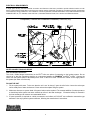
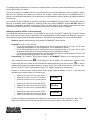
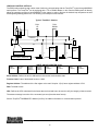
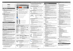
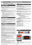
OPERATING INSTRUCTIONS
EMBLEM® GAS-FIRED MULTIPLE BOILER HEATING SYSTEM
Installation and service must be performed by a qualified service installer, service agency or the gas supplier.
THIS MANUAL CONTAINS INFORMATION REQUIRED FOR OPERATION AND MAINTENANCE OF THE EMBLEM®
GAS-FIRED MULTIPLE BOILER HEATING SYSTEM. REFER TO INDIVIDUAL PRIMERA® AND EPV® BOILER
INSTALLATION AND MAINTENANCE MANUALS FOR INSTRUCTIONS, WARNINGS AND IMPORTANT INFORMATION
ABOUT THE INSTALLATION, OPERATION AND MAINTENANCE FOR EACH OF THE BOILERS IN THIS HEATING
SYSTEM. READ AND FOLLOW ALL INSTRUCTIONS, MARKINGS AND WARNINGS BEFORE ATTEMPTING TO
START AND OPERATE EITHER BOILER.
TO THE INSTALLER: After installation, these instructions must be given to the equipment user or left near the appliance.
Refer to I & M documents 34-50, 34-501 and 34-502 for additional important information.
SPECIAL INSTRUCTIONS TO THE OWNER: Retain this manual for future reference.
important information that will help you in maintaining and operating this appliance.
These instructions contain
CHECKING EQUIPMENT BEFORE YOU INSTALL - Upon receiving equipment, check for signs of shipping damage.
Inspect the appliance and all accompanying parts for signs of impact or mishandling. Verify the total number of pieces
shown on packing slips with those actually received. If there is damage or a shortage, contact the carrier immediately.
WARRANTY - Factory warranty does not cover improper installation or operation. (See individual PRIMERA® and EPV®
boiler warranties for complete details).
Riverside Hydronics®, LLC - 990 Haltom Road - Fort Worth, Texas 76117 - Tel 1-800-990-5918
1
34-500 09/07
CONTENTS
TOPIC
PAGE
General Safety Warnings and Codes
1&2
TOPIC
PAGE
Heating Boiler System Piping
5
EMBLEM® Overview
2
Piping Illustration
6
Electrical and Water Connections
3
Water Considerations
7
Operation and General Information
4
Lead/Lag Systems
General Information
4
8-10
WARNING: Improper installation, adjustment, alteration, service or maintenance can cause property
damage, personal injury, exposure to hazardous materials or loss of life. Refer to and follow the information
contained in this manual, the PRIMERA® I&M, the EPV® I&M, all provided documents labels and warnings.
Installation and service must be performed by a qualified installer, service agency or the gas supplier, who
must read and follow all supplied instructions before installing, servicing or removing these appliances.
EMBLEM® OVERVIEW - The EMBLEM® is a boiler heating system that interconnects a condensing boiler
with a non-condensing boiler and uses a control algorithm to fire each or both boilers as necessary to meet
the building heat requirements while providing maximum efficiency throughout the heating season.
During periods of low to medium building heat demand, whether seasonal or occupancy driven or both,
significant fuel savings can be realized by reducing the boiler loop temperature. A condensing boiler offers
the greatest value to building owners when loop temperatures are low enough (< 130°F) to allow the water
vapor in flue products to condense inside the boiler where the latent energy (heat) of condensation is
captured. The condensing boiler in the EMBLEM® system is sized to meet the output requirement during low
to medium heat demand. Because it captures the latent heat released during condensation, thermal
efficiency ranges from 93% to 99% depending upon return water temperature and firing rate. A modular
arrangement of non-condensing boilers, even with modulation, is unable to capture this heat and, as a
result, is less efficient.
During periods of higher building heat demand, loop temperatures are normally elevated and are too high to
allow condensing of flue gases. As a result, firing additional condensing boilers with loop temperatures
greater than 130°F offers little efficiency advantage compared to non-condensing boilers. When heat
demand and loop temperatures are high, the EMBLEM® system engages a non-condensing boiler to
supplement heat output. Although non-condensing, the secondary boiler in the EMBLEM® system still
operates at relatively high efficiency of 85%. The combined output of each boiler in the EMBLEM® system
meets building demand during the coldest days of the heating season.
Over the heating season, the average output of a boiler system is approximately 35% of its total heating
capacity. Such oversizing is unavoidable because of the few unusually cold days when maximum heating
system output is essential to building comfort. EMBLEM® intelligently combines boilers of different
efficiencies and fires those boilers when appropriate during the heating season to meet all heat
requirements and maximize fuel savings for the building owner.
Riverside Hydronics®, LLC - 990 Haltom Road - Fort Worth, Texas 76117 - Tel 1-800-990-5918
ELECTRICAL REQUIREMENTS
A single point 30-amp, 240-volt electrical connection and disconnect has been provided to provide electrical service to both
boilers. Both boilers and the skid on which they are resting must be electrically grounded in accordance with the requirements
of the authority having jurisdiction or in the absence of such requirements, with the latest edition of the National Electrical Code
ANSI/NFPA No. 70, or in Canada, to the CAE C22.1, Canadian Electrical Code, Part 1 and/or Local Electrical Codes.
Component, Controls and Connection Locations (Locations May Vary)
WATER CONNECTIONS AND PIPING
Inlet and Outlet Connections
The 4-inch, 150lbs flanged connections on the EPV® boiler are points of connection to the heating system. Do not
connect to or alter the connecting plumbing or components between the PRIMERA® and EPV® boilers. Connect the
return from the system (water to be heated) to the “Inlet” of the EPV® boiler. Connect the “Outlet” to the supply side of
the system (hot water out of the unit).
FILLING THE UNIT
1. Fill the system with water. To be sure that the unit is not “air bound,” open the relief valve. Leave the valve open
until a steady flow of water is observed. Close valve and complete filling the system.
2. Make sure there are no system leaks. All system leaks must be repaired. The constant addition of make-up water to
a closed loop boiler system can cause minerals to collect in the heat exchanger. Excessive buildup of minerals in
the heat exchanger can cause a non-warrantable failure.
3. If freeze protection is required on a boiler connected to an indirect coil, DO NOT use undiluted or automotive type
antifreeze. Use only hydronic system antifreeze, following the manufacturer’s instructions.
Riverside Hydronics®, LLC - 990 Haltom Road - Fort Worth, Texas 76117 - Tel 1-800-990-5918
3
OPERATION
LOW WATER CUTOFF - Proper function of the low water cutoffs should be verified every six months. See individual
boiler Installation & Maintenance manuals for details.
OPERATING TEMPERATURE CONTROL - An adjustable digital operating control, TempTrac®, is located in the front
control panel of the PRIMERA® boiler. This control uses a remote sensing bulb mounted in the outlet fitting of the EPV®
boiler. The function of this control is specially designed to coordinate the operation as well a firing rate of both boilers in
order to match the heat load of the system while maximizing the fuel efficiency. Do not attempt to alter control system
parameters without factory direction. Improper adjustments could disable operation.
The sequence of control logic could be as follows:
1. System heat demand is at a minimum, the EPV® boiler fires at the lowest firing rate, periodically cycling. This
condition is the most efficient operation.
2. System demand increases and the TempTrac® will stage the EPV® boiler between the lowest firing rate and the
highest firing rate, in order to match heat delivery to system heat demand. This condition continues to operate at
a high efficiency.
3. System heat demand further increases as system approaches peak heat demand. The TempTrac® now enables
the PRIMERA® boiler and simultaneously reduces the firing rate of the EPV® boiler to it lowest firing rate. The
TempTrac® will now modulate the PRIMERA® boiler between its lowest and highest firing rate in order to
precisely match the system heat demand.
4. System heat demand now reaches the peak heat demand and the TempTrac® may now enable the EPV® boiler
as well. The TempTrac® is able to simultaneously modulate the PRIMERA® boiler and stage the EPV® boiler in
order to respond to this peak demand.
The diagram titled “EMBLEM® Control Logic” illustrates the operation of this system at a set-point of 155°F.
To adjust the set point of the TempTrac® to deliver the desired water temperature, press and release the Set key on the face of
the control. Set-point 1 (St1) parameter is the first to be displayed. Press the Set key again and adjustment is enabled. Use
the arrow keys to adjust the set-point 1 to the desired system temperature and press the set key again to lock it in. DO NOT
change the other set-points in this menu.
GENERAL INFORMATION
RELIEF VALVE - Both heating boilers are normally supplied with a pressure only relief valve(s) sized in accordance with
the ASME Boiler and Pressure Vessel Code, Section IV; 150 psig/250 °F maximum.
Caution: Do not install a reducing coupling, valve or other restriction in the relief valve(s) discharge line. The discharge
line shall allow complete drainage of the valve and line. Relief valves should be manually operated at least once a year.
WARNING: To prevent burns caused by hot water discharge and water damage, the discharge from both relief
valves must be piped to a suitable floor drain for disposal when relief occurs. Avoid contact with hot discharge
water.
THERMAL EXPANSION - A relief valve that discharges periodically may be due to thermal expansion in a closed
system. This system must be provided with means to control expansion. Contact a boiler or plumbing professional to
resolve this situation. Do not plug the relief valve.
AUTOMATIC OVERRIDE SWITCH – This 2 position switch is located on the main power disconnect panel. In the event that a
failure of the electronic temperature control occurs or the PRIMERA® boiler is temporarily removed from service, the automatic
override switch can be set Manual Override, allowing the EPV® boiler to function independently of the EMBLEM® control
system.
HIGH WATER TEMPERATURE LIMIT CONTROL – Both boilers are equipped with adjustable limit and high limit
controls to control the maximum discharge water temperature. (See: Individual boiler Installation & Maintenance
manuals for additional details about temperature limits).
WARNING: Turn off all electrical service to the appliance when accessing the limit or high limit controls located
inside the electrical enclosures. If the electrical service is not turned off and these terminals are touched, a
dangerous shock causing personal injury or loss of life could occur.
Riverside Hydronics®, LLC - 990 Haltom Road - Fort Worth, Texas 76117 - Tel 1-800-990-5918
4
SPECIAL DESIGN APPLICATIONS
The EMBLEM® boiler system, when used in connection with a refrigeration system, must be installed so the chilled
medium is piped in parallel with the boiler with appropriate valves to prevent the chilled medium from entering the boiler.
The boiler piping system of the EMBLEM® (when connected to heating coils located in air handling units where they may
be exposed to refrigerated air circulation) must be equipped with flow control valves or other automatic means to prevent
gravity circulation of the boiler water during the cooling cycle.
PERFORMANCE DATA
The EMBLEM® boiler system is capable of operating with very low flow rates due to the water buffer contained in the
EPV® boiler. It is recommended however that when variable speed pumps are applied, the minimum flow rate should be
sufficient to promote fast accurate response to system demands.
The EMBLEM® boiler system is also capable of operating with very low return temperatures. It is recommended in fact
the return temperature be as low as possible in order to maximize the efficiency of the system.
MAINTENANCE
See individual boiler Installation & Maintenance manuals for details about product maintenance.
WARNING: When servicing the controls, use exact, Factory authorized, replacement parts and label all wires
prior to disconnection. Verify proper operation after servicing. Incorrect parts substitution and wiring errors
can cause damage, improper operation, fire, carbon monoxide and other unexpected and unsafe conditions
that could result in fire, injury or death.
HEATING BOILER SYSTEM PIPING:
The design document on the following page illustrates examples of both a primary only and a primary – secondary
hydronic system for single or multiple boiler systems. This is intended as a general guide for use with the EMBLEM®
systems. There are many other layout combinations which are not shown but could be adopted due to the inherent
®
flexibility of the EMBLEM system.
The Primary Only System is generally not applied with modern PRIMERA® boiler systems, due to the need to maintain
a constant flow rate through the boiler. The cost saving associated with these system can only be realized with the
application of a medium to high mass boiler. The use of VFD pumping has improved functionality of primary only
systems but has further increased the risk to PRIMERA® boiler systems. The EMBLEM® is well suited for the primary
only system.
The Primary – Secondary System most commonly applied to today due to the desire to control the operational
conditions of the boiler loop separately from the secondary building loop. This system is also more reliably applied when
heating systems become too large to adequately maintain the proper flow rates and temperature drops across the
individual heating zones.
The following recommendation should be considered when designing both systems:
• Always attempt to apply reverse return piping method to help equalize water flow and simplify balancing of the
circuits.
• Centrifugal system circulating pumps are shown. Circulating pumps should be electrically interlocked with the
boiler control circuit. The boiler should not fire unless the circulating pumps are running. In the case of VFD
pumping some minimums threshold of flow should be established and likewise interlocked with the boiler.
• Use balancing valves in the supply lines from each boiler to the pumps in order to help equalize or portion the
flow through the boilers.
• A make-up water meter must be installed in any raw water feed to the system.
• A means for introducing chemicals to the system water must be provided.
• One expansion tank for multiple boilers is typically sufficient when sized properly.
• A (BMS) boiler management system with Lead/Lag functionality should be used for systems with multiple
boilers.
• When using multiple boilers it is recommended that a motorized flow control valve be used in the inlet and
controlled by the boiler demand or BMS.
Riverside Hydronics®, LLC - 990 Haltom Road - Fort Worth, Texas 76117 - Tel 1-800-990-5918
5
Riverside Hydronics®, LLC - 990 Haltom Road - Fort Worth, Texas 76117 - Tel 1-800-990-5918
6
WATER CONSIDERATION
WATER CONDITIONING - Every new system will have certain harmful substances which remain in the boiler and piping
after construction. It is com to find oils, weld slag, and other contaminates within the system. If the foreign materials
remain, the boiler could be affected by loss of heat transfer on heat exchanger surfaces and/or an acidic water condition.
Boiler life may be reduced as a result of an unclean system.
A water treatment company will be able to recommend a chemical cleaning or boil-out procedure.
CHEMICAL TREATMENT - It is recommended that chemical treatment be provided for initial fill of the system.
Generally, chemicals will be required to prevent scale formation, promote elimination of dissolved gases and control pH.
Most hot water boilers operate in a closed system and are considered to require little attention for water treatment.
Experience has shown, however, few systems can be considered completely closed. Loss of water can occur from
pump packing, glands, air venting devices, and threaded or flanged pipe connections. A means must be provided to
chemically treat the raw water make-up. This is generally accomplished through the use of a shot-type chemical feeder.
Consult a water treatment company for details.
MAKE-UP WATER - It is generally accepted in system design that hat water boilers are in a closed system and,
therefore, no make-up water is needed. This is not always the case. Untreated make-up water is a leading cause for
failures of hat water boilers. Provisions must be made for properly introducing, metering, and treating make-up water.
Below are some considerations.
• Provision should be made for removal of air from the make-up water.
• It is recommended that make-up water be tempered so as not to introduce cold water to the system.
• A raw water meter should be used to identify the amount of water used by the system. This may indicate a
potential problem with the system.
ETHYLENE GLYCOL AS HEAT TRANSFER MEDIUM - On application requiring freeze protection, a mixture of
ethylene glycol and water is commonly used.
When using ethylene glycol certain design limitations are important, due to the characteristics of the fluid verses water.
These characteristics are: Elevated saturation temperature, and increased viscosity and density. In addition, ethylene
glycol degrades when it is heated above the manufacturer’s specified maximum film temperature.
The following design parameters must be followed when operating EMBLEM® with ethylene glycol:
• The maximum concentration should be 50%.
• Maximum temperature 200°F.
• Minimum operating pressure 50 psig.
• A means of monitoring the condition of the system fluid should be provided. Frequent analysis of the system
should be conducted in the first few month of operation. Simi-annual checks thereafter are recommended.
• Excessive use of inhibitors can create precipitation of solids causing reduce circulation and reduced heat
transfer.
Riverside Hydronics®, LLC - 990 Haltom Road - Fort Worth, Texas 76117 - Tel 1-800-990-5918
LEAD/LAG SYSTEMS
7
A Lead/Lag system sequences the on-off firing of multiple boilers to meet the system load demand and equalize run
time for all the boilers in a system.
The key to the design of a lead/lag control in a hot water system is the control intelligence to react to changes in system
load which are inherently slow without over reacting. The change in boiler output does not immediately result in a
change in overall system temperature. The control system must be designed to take into account the lag times and allow
for fine tuning.
The TempTrac® control is designed to optimize the operation of the EMBLEM® system in order to provide the maximum
efficiency of operation. When interfacing a Lead/Lag system with multiple EMBLEM® systems DO NOT attempt to
interrupt the independent operation of this control. There are three options on the following page which will allow
Lead/Lag and Outdoor Reset control of the EMBLEM® system, while maintaining optimum efficiency.
LEAD/LAG CONTROL OPTION 1: (Recommended)
The lead-lag and outdoor-reset control is accomplished by the on-board TempTrac® controls. The TempTrac® control
has a 7day real time clock which in conjunction with a programmable set-back schedule will alternately reduce the
control set-point by a programmed set-back temperature. The following is an example of a 3 boiler lead-lag schedule:
Objective: Balance operational time evenly between all EMBLEM® boiler systems.
Parameters: E1-E7, S1-S7, Sb1-Sb7
• The E series parameters are the starting point for the programmed shift in set point. The E series
parameters are divided into 10 minute increments. The E1 parameter is Sunday.
• The S series parameters are the ending point for the programmed shift in set point. The S series
parameters are divided into 10 minute increments. The S1 parameter is Sunday.
• The Sb series parameters are the shift in set point imposed for the time period defined by E and S. The
shift in set point can be (-40Fto40F). The Sb1 is Sunday.
Programming: The TempTrac® boiler control located on the PRIMERA® allows for one button access to this
ES
menu. Hold down the up button
until E1 appears in the top display. The up/down arrow buttons will now
in order to
scroll through this menu. When you have reached the desired parameter, push the set button
enable adjustment and the up/down buttons to change the set point. Push the set button to lock in the value.
See the TempTrac® Service & Setup Manual (34-81), for addition information on programming.
Example: A 3 boiler hydronic heating system, with a supply target temperature of 165 F. In this case lead
operation will be divided 3 ways in to a 24 hour day.
•
•
•
Boiler #1 St1=160, E1=0.0, S1=8.0, Sb1=5
Boiler #2 St1=160, E1=8.0, S1=16.0, Sb1=5
Boiler #3 St1=160, E1=16.0 S1=24.0,Sb1=5
Sunday
•
•
•
Boiler #2 St1=160, E2=0.0, S2=8.0, Sb2=5
Boiler #3 St1=160, E2=8.0, S2=16.0, Sb2=5
Boiler #1 St1=160, E2=16.0, S2=24.0,Sb2=5
Monday
•
•
•
Boiler #3 St1=160, E3=0.0, S3=8.0, Sb3=5
Boiler #1 St1=160, E3=8.0, S3=16.0, Sb3=5
Boiler #1 St1=160, E3=16.0, S3=24.0,Sb3=5
Tuesday
The above example would designate the lead boiler by advancing the set point of one boiler by 5 deg F. The
same result could be produced by reducing the set points of the 2 lag boiler. In this case Sb1= -5 deg F.
Riverside Hydronics®, LLC - 990 Haltom Road - Fort Worth, Texas 76117 - Tel 1-800-990-5918
8
A variation on this example might be to shift back the set point on the weekend in order to reduce loop
temperature and save energy beginning 5:00PM Friday. In this case Sb# would be -20 for the lead boiler -25 for
the lag boilers. Target operating temperature would shift from 165 to 145°F. See below.
•
•
•
Boiler #1 St1=160, E6=17.0, S6=24.0, Sb6= -20
Boiler #2 St1=160, E6=17.0, S6=24.0, Sb6= -25
Boiler #3 St1=160, E6=17.0, S6=24.0, Sb6= -25
Friday
•
•
•
Boiler #1 St1=160, E7=0.0, S7=24.0, Sb2= -25
Boiler #2 St1=160, E7=0.0, S7=24.0, Sb2= -20
Boiler #3 St1=160, E7=0.0, S7=24.0, Sb2= -25
Saturday
•
•
•
Boiler #1 St1=160, E1=0.0, S1=24.0, Sb1= -25
Boiler #2 St1=160, E1=0.0, S1=24.0, Sb1= -25
Boiler #3 St1=160, E1=0.0, S1=24.0, Sb1= -20
Sunday
•
•
•
Boiler #2 St1=160, E2=0.0, S2=6.0, Sb2= -20
Boiler #3 St1=160, E2=0.0, S2=6.0, Sb2= -25
Boiler #1 St1=160, E2=0.0, S2=6.0, Sb2= -25
Monday
LEAD/LAG CONTROL OPTION 2:
The lead-lag and outdoor reset function is managed by a third party Boiler Management System (BMS) or building
Energy Management System (EMS). This manner of control will only function to enable-disable the EMBLEM® boiler
system. Once enable the TempTrac® boiler control must be allowed to function independently in order to ensure efficient
operation. If outdoor reset is desired the TempTrac® outdoor reset function must be utilized and the programming
function must be identical to the BMS or EMS control.
See the TempTrac® Service & Setup Manual (34-81), for addition information on programming the outdoor reset
function.
Terminals R1 & R2 located in the control kiosk provide enable/disable electrical interface. Remove the jumper to
interrupt automatic control of the EMBLEM® boiler system.
Riverside Hydronics®, LLC - 990 Haltom Road - Fort Worth, Texas 76117 - Tel 1-800-990-5918
9
LEAD/LAG CONTROL OPTION 3:
The EMS performs lead-lag and outdoor reset function by communicating with the TempTrac® control through MODBUS
serial protocol. The TempTrac® can be equipped with a TTL to RS485 adapter. In this case the EMS system will directly
adjust the operating set point of each EMBLEM® boiler system in order to achieve the desired loop temperature as well
as designating lead-lag preference. The following is an example of this interface:
Typical “Two-Wire” Solution
Master
PULL
DOWN
PULL
UP
COMMON
D1
L
L
D0
Temp
Trac®
TXD0&RXD0
TXD1& RXD1
-
Temp
Trac®
+
-
+
XJ485 SERIAL INTERFACE
WRITE SINGLE REGISTER (0x06):
Slave
Address
Function
Code
Register
Address
(MSByte)
Register
Address
(LSByte)
Data
(MSByte)
Data
(LSByte)
CRC
(LSByte)
CRC
(MSByte)
Slave Address: Defines the device address that receives the communication data.
Function Code: Code of the desired function = 0X06
Register Address: The address of the first register to be read. Set point 1 (St1) has a register address of 768
Data: The data to write
CRC: Defines the CRC calculated for the frame data received and has to be used to verify the integrity of data received.
The answer message is an echo of the command you sent (it has the same format).
See the TempTrac® MODBUS-RTU Manual (34-502), for addition information on communication protocol.
Riverside Hydronics®, LLC - 990 Haltom Road - Fort Worth, Texas 76117 - Tel 1-800-990-5918
10