1
321-78001C
MAR. 2013
Requests
•
•
Provide this manual to the next user in the event that the instrument is transferred.
To ensure safe operation, contact your Shimadzu Balance representative for installation, adjustment, or
reinstallation after moving the instrument to a different site.
Notices
•
•
•
•
•
•
The content of this manual is subject, without notice, to modifications for the sake of improvement.
Every effort has been made to ensure that the content of this manual was correct at the time of creation.
However, in the event that any mistakes or omissions are discovered, it may not be possible to correct
them immediately.
The copyright of this manual is owned by Shimadzu Corporation. Reproduction and duplication of whole
or part of the content without permission of the company are strictly prohibited.
© 2009-2013 Shimadzu Corporation. All rights reserved.
"Microsoft", "Windows", and "Excel" are registered trademarks of Microsoft Corporation of the U.S.A.
in the United States and other countries. All other company names and product names that appear in
this manual are trademarks or registered trademarks of the companies concerned. Note that ™ and ®
indications are not used.
The company names, organization names and product names in this manual are trademarks or registered
trademarks of the companies and organizations concerned.
Shimadzu does not guarantee that the WindowsDirect communication function will operate without
problems on all PCs. Shimadzu will accept no responsibility for any trouble that arises as a result of using
this function. You are recommended to back up all important data and programs in advance.
Introduction
Thank you for purchasing a Shimadzu ATX/ATY series electronic
balance.
The ATX/ATY series models are high performance electronic
balances that we confidently recommend based on over 90 years of
precision balance manufacture. While these models are of course
capable of fast and accurate weighing, the models all use the
Unibloc cells that Shimadzu started using for electronic balances
in 1989, improv the reliability of the balances still further.
These balances also feature a variety of other functions that
make it more convenient for customers to use them for their
own applications, including the WindowsDirect communication
function, which enables measuring results to be transferred to a
PC without installing any software.
To ensure that you can make full use of the performance and
functions of your ATX/ATY series balance, read this instruction
manual carefully and use the balance correctly in accordance with
the directions in the manual. When you have finished reading the
manual, keep it in a safe place together with the balance so that
you can refer to it at any time.
For information on the following points, please contact your
Shimadzu Balance representative.
•
•
Product warranty
After service
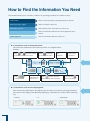
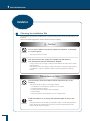
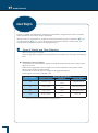
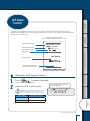
How to Find the Information You Need
This manual allows you to search for a function or operating procedure in a number of ways.
"Cover index"
Search for the information by thumbing through the manual.
"What You Can Do", page 6
Search for what you want to do.
"Menu Map", page 143
Search quickly for the menu option you want to use.
Search for information based on its order of appearance in the
manual.
"Index", page 148
Search for information based on a key word.
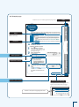
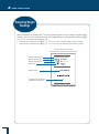
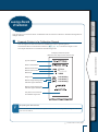
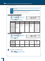
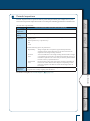
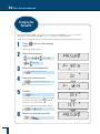
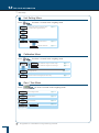
Conventions used in menu operations
The instruction manual describes menu operations in a simplified form.
Example:
Press
or
a number of times
Press
to search for the next menu option.
Press
confirm.
to
to proceed
to the next menu option.
Information
indicated in the
display panel
Press
User
operations
Flow of menu
operations
Press and hold
a number of times to
return to a higher level of the menu.
(about 3 seconds).
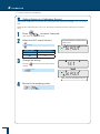
Conventions used for the display panel
This instruction manual depicts the display panel in relation to particular operating procedures.
The actions of the display panel (flashing, lighting up, confirmation) are shown in the following
way.
•
Flashing
•
////
////
// /
///
Lit
•
Confirmation
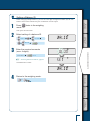
Example page
Linked to the cover index (right-hand pages only)
Index
Notes
Information to help use the
balance correctly
Reference
Menu operation
Explanation of terms
Depiction of the display
Continued on next page
The symbol shown in the figure below
appears at the head of the next page.
The title of the previous page appears here.
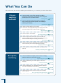
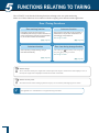
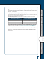
What You Can Do
This section lets you search for a method you would like to try or a function you want to know about.
Various
weighing
methods
n I want to weigh up to a fixed quantity by adding
increments of the same sample (item to be weighed:
powder, liquid, etc.) a little at a time.
Pouring Mode
page 69
n I want to make fine adjustments during weighing,
like increasing the reaction speed of the display or
stabilizing the display.
Easy Setting
page 70
n I want to set unit weights (the weight of a single piece of the
item being weighed) for multiple samples in advance.
Piece Counting
page 81
n I want to use the balance to count items.
n I want to weigh in percentages.
Percentage Weighing
Zero point, and taring
page 86
n I want to weigh a fixed amount of each of a number of
different samples (items to be weighed: powder, liquid, etc.)
and to mix these samples according to a formula.
Formulation
page 90
n I want to check excess or deficiency with respect to a target
value and make "pass or fail" judgments accordingly.
Comparator Function
page 96
n I want to adjust the conditions under which the stability mark
lights up.
Adjusting the Stability Mark
page 74
n I want to stabilize the display at zero when an empty
sample container is placed on the pan.
Zero Tracking Function
page 63
n I want to automatically return the display to zero after
weighing.
Auto Zero Function
page 64
n I want to automatically tare the balance (set the display to
zero) after outputting a weight reading.
Auto Tare Function
page 66
n I want to tare the balance without waiting for the stability
mark to light up.
Zero / Tare Timing Change Function
page 67
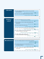
Calibration
n I want to adjust the balance so that it is very accurate
after stabilization.
Span Calibration and Adjustment
page 54
n I want to carry out calibration and output a record.
Leaving a Record of Calibration
Printing /
output
page 59
n I want to send data to a PC (e.g. to Excel).
WindowsDirect Communication Function
page 105
n After weighing, I want to output automatically upon
stabilization.
Auto Print Function
page 100
Continuous Output Function
page 104
n I want to output data continuously.
n I want to output data either immediately or after stabilization.
Output Timing Change Function
page 123
n I want to change the format of the decimal point
(comma or period) in the output data.
Selecting the Decimal Point Display Symbol
page 37
n I want to add the balance model name,
ID and other information to weight readings.
GLP Output Function
Miscellaneous
page 135
n I want to display weights in units other than g (grams).
Switching Units
page 35
Setting the Units
page 76
n I want the power to turn off automatically when I am
not using the balance.
Auto Power-Off Function
page 132
n I want to go directly into weighing mode when the power is
switched ON.
Setting the Startup Display
page 133
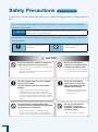
Safety Precautions
To be strictly observed
To ensure that you use the balance safely and correctly, read the following precautions carefully and observe
them.
The levels of danger and damage that will arise if the balance is used incorrectly are classified and
indicated as shown below.
! CAUTION
Indicates a potentially hazardous situation which, if not avoided, may result in minor to
moderate injury or equipment damage.
Precautions are classified and explained by using one of the symbols below, depending on the nature
of the precaution.
Instructions
Indicates an action that must be
performed.
Prohibitions
Indicates an action that must
NOT be performed
! CAUTION
Never disassemble, modify or attempt to
repair this product or any accessory.
Prohibitions
Instructions
You could sustain an electric shock or the product could
operate abnormally.
If you believe that the balance has failed, contact your
Shimadzu representative.
Use the balance with the correct power
supply and voltage.
Use the balance with the attached AC
adapter.
Prohibitions
You could sustain an electric shock or
the product could operate abnormally.
Instructions
Prohibitions
If you do, the balance may stop working normally.
In order to avoid trouble, always connect peripheral
devices in accordance with the directions in this manual.
If you detect anything
abnormal (e.g. a burning
smell) disconnect the AC
adapter immediately.
Continuing to use the balance with
an abnormality could lead to fire or
an electric shock.
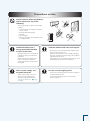
Using the balance with an incorrect power supply or
voltage will lead to fire or trouble with the balance.
Note also that if the power supply or voltage is unstable
or if the power supply capacity is insufficient, it will not
be possible to obtain satisfactory performance from the
balance.
Do not connect anything other than
peripheral devices specified by Shimadzu
to the balance’s connector.
Do not use the balance
outdoors or anywhere where
it will be exposed to water.
Prohibitions
Do not use the balance
anywhere exposed to
explosive, combustible or
corrosive gases.
This could cause fire or trouble.
Precautions on Use
Prohibitions
Avoid locations where the balance
will be exposed to any of the
following.
You may not be able to obtain correct weight
readings.
• Air flow from an air conditioner, ventilator,
door or window
• Extreme temperature changes
• Vibration
• Direct sunlight
• Dust, fine particles, electromagnetic waves
or a magnetic field
Instructions
Install the balance on a
strong and stable flat table
or floor in the room.
Treat the balance with care and respect.
Instructions
Placing the balance in an unstable site
could lead to injury or trouble with
the balance.
When selecting the installation site,
take into account the combined
weight of the balance and the item to
be weighed.
Use the correct weighing units.
After a power outage, turn
the power back ON.
Instructions
When a power outage occurs, the
power is shut off automatically.
Therefore, begin operation from
"Turning the Power ON" (^ page
29) again.
The balance is a precision instrument. Subjecting it to
impacts could cause it to fail.
When moving the balance, remove fixing of the glass
door, pan, pan supporter and pan rings. Grasp it firmly
with both hands to carry it.
If the balance has to be stored for a long time, store it in
the packaging box in which it was delivered.
Instructions
Using incorrect weighing units can lead to accidents as
a result of weighing errors.
Check that the weighing units are correct before
starting weighing.
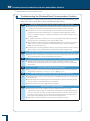
Shimadzu Balances and 21 CFR Part 11
21 CFR Part 11
21 CFR Part 11, Electronic Records, Electronic Signatures, Final
Rule (often referred to as Part 11) is the United States Food and Drug
Administration (FDA) regulation affecting computer resources and
electronic records that are used for any document that is required to be
kept and maintained by FDA regulations.
Requirements concerning computer resources security are key
elements in Part 11.
The controls implemented as a result of security related requirements
are intended to result in trusted records.
Shimadzu CLASS-Balance Agent
Shimadzu provides a means for compliance with 21 CFR Part 11 with
Shimadzu CLASS-Balance Agent software, part of a comprehensive
laboratory data management system, Shimadzu CLASS Agent.
Ask your Shimadzu representative about it.
Shimadzu WindowsDirect
When Shimadzu balances are integrated with laboratory software by
means of our WindowsDirect function, no communication software is
required or used.
The Shimadzu balance functions as a primary device in the system,
just as a keyboard, mouse or other data entry hardware does.
For this reason, system validation and compliance may be greatly
simplified with the use of Shimadzu balances.
Two-way Communication
Shimadzu balances have always been computer friendly and they can
be set up for bi-directional communication as part of a fully automated
production system or LIMS.
This manual includes the command codes and information needed by
programmers to integrate Shimadzu balances with their software.
10
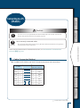
Action for Environment (WEEE)
To all user of Shimadzu equipment in the European Union:
Equipment marked with this symbol indicates that it was sold on or after 13th August 2005,
which means it should not be disposed of with general household waste. Note that our equipment
is for industrial/professional use only.
Contact Shimadzu service representative when the equipment has reached the
end of its life. They will advise you regarding the equipment take-back.
With your co-operation we are aiming to reduce contamination
from waste electronic and electrical equipment and preserve natural
resource through re-use and recycling.
Do not hesitate to ask Shimadzu service representative, if you require
further information.
WEEE Mark
11
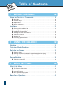
Table of Contents
Table of Contents
1 BEFORE WEIGHING
18
Name and Function of Components . . . . . . . . . . . . . . . . . . . . . . . . . . 18
■ Main body. . . . . . . . . . . . . . . . . . . . . . . . . . . . . . . . . . . . . . . . . . . . . . . . . . . . . . . . . . . 18
■ Operation Keys. . . . . . . . . . . . . . . . . . . . . . . . . . . . . . . . . . . . . . . . . . . . . . . . . . . . . . . 19
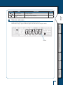
■ Display Panel. . . . . . . . . . . . . . . . . . . . . . . . . . . . . . . . . . . . . . . . . . . . . . . . . . . . . . . . 20
■ Numeric value area . . . . . . . . . . . . . . . . . . . . . . . . . . . . . . . . . . . . . . . . . . . . . . . . . . . 21
Installation. . . . . . . . . . . . . . . . . . . . . . . . . . . . . . . . . . . . . . . . . . . . . . 22
■ Choosing the Installation Site . . . . . . . . . . . . . . . . . . . . . . . . . . . . . . . . . . . . . . . . . . . 22
■ Unpacking and Delivery Inspection. . . . . . . . . . . . . . . . . . . . . . . . . . . . . . . . . . . . . . . 23
■ Installing the Components. . . . . . . . . . . . . . . . . . . . . . . . . . . . . . . . . . . . . . . . . . . . . . 24
■ Adjusting the Level of the Balance. . . . . . . . . . . . . . . . . . . . . . . . . . . . . . . . . . . . . . . . 24
■ Turning the Power ON. . . . . . . . . . . . . . . . . . . . . . . . . . . . . . . . . . . . . . . . . . . . . . . . . 26
■ Warming Up. . . . . . . . . . . . . . . . . . . . . . . . . . . . . . . . . . . . . . . . . . . . . . . . . . . . . . . . . 27
■ Performing Span Calibration. . . . . . . . . . . . . . . . . . . . . . . . . . . . . . . . . . . . . . . . . . . . 28
2 USING THE BALANCE
32
Weighing. . . . . . . . . . . . . . . . . . . . . . . . . . . . . . . . . . . . . . . . . . . . . . . 32
Outputting Weight Readings. . . . . . . . . . . . . . . . . . . . . . . . . . . . . . . . 34
Selecting the Display. . . . . . . . . . . . . . . . . . . . . . . . . . . . . . . . . . . . . . 35
■ Switching Units. . . . . . . . . . . . . . . . . . . . . . . . . . . . . . . . . . . . . . . . . . . . . . . . . . . . . . . 35
■ Selecting the Minimum Number of Displayed Digit (1d/10d display). . . . . . . . . . . . . . 35
■ Selecting the Decimal Point Display Symbol. . . . . . . . . . . . . . . . . . . . . . . . . . . . . . . . 37
Ending Weighing. . . . . . . . . . . . . . . . . . . . . . . . . . . . . . . . . . . . . . . . . 39
■ Turning the Power OFF . . . . . . . . . . . . . . . . . . . . . . . . . . . . . . . . . . . . . . . . . . . . . . . . 39
3 MENU SETTINGS
40
What Is the Menu? . . . . . . . . . . . . . . . . . . . . . . . . . . . . . . . . . . . . . . . 40
■ The Structure of the Menu. . . . . . . . . . . . . . . . . . . . . . . . . . . . . . . . . . . . . . . . . . . . . . 40
■ Menu Map . . . . . . . . . . . . . . . . . . . . . . . . . . . . . . . . . . . . . . . . . . . . . . . . . . . . . . . . . . 41
■ Instruction Manual. . . . . . . . . . . . . . . . . . . . . . . . . . . . . . . . . . . . . . . . . . . . . . . . . . . . 41
■ Menu Operation Key Symbol. . . . . . . . . . . . . . . . . . . . . . . . . . . . . . . . . . . . . . . . . . . . 41
Basic Menu Operations. . . . . . . . . . . . . . . . . . . . . . . . . . . . . . . . . . . . 42
12
Entering Numerical Values . . . . . . . . . . . . . . . . . . . . . . . . . . . . . . . . . 43
BEFORE
WEIGHING
■ Changing the Numerical Value . . . . . . . . . . . . . . . . . . . . . . . . . . . . . . . . . . . . . . . . . . 43
■ Changing the Position of the Decimal Point. . . . . . . . . . . . . . . . . . . . . . . . . . . . . . . . . 44
Convenient Functions for Menu Setting. . . . . . . . . . . . . . . . . . . . . . . . 45
■ Returning to the Default Settings (Menu Reset) . . . . . . . . . . . . . . . . . . . . . . . . . . . . . 45
■ Prohibiting Changes to the Menu Settings (Menu Lock). . . . . . . . . . . . . . . . . . . . . . . 46
■ Outputting the Menu Setting Information. . . . . . . . . . . . . . . . . . . . . . . . . . . . . . . . . . . 47
USING THE
BALANCE
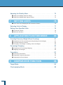
4 CALIBRATION
48
Before Starting Calibration…. . . . . . . . . . . . . . . . . . . . . . . . . . . . . . . . 48
Automatic calibration (ATX only). . . . . . . . . . . . . . . . . . . . . . . . . . . . . 50
USING MORE CONVENIENTLY
Announcement of calibration request (ATY only). . . . . . . . . . . . . . . . . . . . . . . 51
Span Calibration and Adjustment . . . . . . . . . . . . . . . . . . . . . . . . . . . . 52
Calibration of the Internal Weight (ATX Only) . . . . . . . . . . . . . . . . . . . 56
Leaving a Record of Calibration . . . . . . . . . . . . . . . . . . . . . . . . . . . . . 59
■ Example Printout of a Calibration Record. . . . . . . . . . . . . . . . . . . . . . . . . . . . . . . . . . 59
■ Setting Output of a Calibration Record . . . . . . . . . . . . . . . . . . . . . . . . . . . . . . . . . . . . 60
■ Setting a Balance ID . . . . . . . . . . . . . . . . . . . . . . . . . . . . . . . . . . . . . . . . . . . . . . . . . . 61
MAINTENANCE
5 FUNCTIONS RELATING TO TARING
62
Zero Tracking Function . . . . . . . . . . . . . . . . . . . . . . . . . . . . . . . . . . . . 63
TROUBLESHOOTING
Auto Zero Function . . . . . . . . . . . . . . . . . . . . . . . . . . . . . . . . . . . . . . . 64
Auto Tare Function . . . . . . . . . . . . . . . . . . . . . . . . . . . . . . . . . . . . . . . 66
Zero / Tare Timing Change Function. . . . . . . . . . . . . . . . . . . . . . . . . . 67
FOR YOUR
INFORMATION
6 ADJUSTING RESPONSE AND STABILITY 68
Selecting the Weighing Mode . . . . . . . . . . . . . . . . . . . . . . . . . . . . . . . 69
■ Selecting the General Weighing Mode . . . . . . . . . . . . . . . . . . . . . . . . . . . . . . . . . . . . 69
■ Selecting the Pouring Mode. . . . . . . . . . . . . . . . . . . . . . . . . . . . . . . . . . . . . . . . . . . . . 69
Easy Setting of Response and Stability. . . . . . . . . . . . . . . . . . . . . . . . 70
13
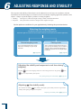
Adjusting the Stability Mark. . . . . . . . . . . . . . . . . . . . . . . . . . . . . . . . . 72
■ Setting the Stability Detection Range . . . . . . . . . . . . . . . . . . . . . . . . . . . . . . . . . . . . . 72
■ Setting the Stability Mark Lighting Timing. . . . . . . . . . . . . . . . . . . . . . . . . . . . . . . . . . 73
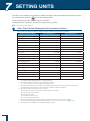
7 SETTING UNITS
76
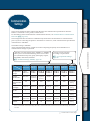
■ Units That Can Be Displayed and Conversion Factors. . . . . . . . . . . . . . . . . . . . . . . . 76
Selecting Units to Display . . . . . . . . . . . . . . . . . . . . . . . . . . . . . . . . . . 77
Setting User-Specified Units. . . . . . . . . . . . . . . . . . . . . . . . . . . . . . . . 78
■ Conversion Factors . . . . . . . . . . . . . . . . . . . . . . . . . . . . . . . . . . . . . . . . . . . . . . . . . . . 78
■ Minimum Indication . . . . . . . . . . . . . . . . . . . . . . . . . . . . . . . . . . . . . . . . . . . . . . . . . . . 79
8 APPLICATION FUNCTION MODE
80
Counting Pieces by Weight (Piece Counting) . . . . . . . . . . . . . . . . . . . 81
■ Preparation for Piece Counting (Including Setting the Unit Weight) . . . . . . . . . . . . . . 81
■ Counting Numbers of Pieces. . . . . . . . . . . . . . . . . . . . . . . . . . . . . . . . . . . . . . . . . . . . 84
■ Changing a Unit Weight, or Adding a New Unit Weight. . . . . . . . . . . . . . . . . . . . . . . . 85
Percentage Weighing . . . . . . . . . . . . . . . . . . . . . . . . . . . . . . . . . . . . . 86
■ Preparation for Percentage Weighing. . . . . . . . . . . . . . . . . . . . . . . . . . . . . . . . . . . . . 86
■ Weighing Percentages. . . . . . . . . . . . . . . . . . . . . . . . . . . . . . . . . . . . . . . . . . . . . . . . . 89
Formulation. . . . . . . . . . . . . . . . . . . . . . . . . . . . . . . . . . . . . . . . . . . . . 90
■ Performing Formulation. . . . . . . . . . . . . . . . . . . . . . . . . . . . . . . . . . . . . . . . . . . . . . . . 90
■ Outputting Component Numbers. . . . . . . . . . . . . . . . . . . . . . . . . . . . . . . . . . . . . . . . . 93
■ Outputting the Gross Weight. . . . . . . . . . . . . . . . . . . . . . . . . . . . . . . . . . . . . . . . . . . . 94
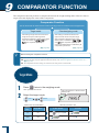
9 COMPARATOR FUNCTION
96
Target Mode . . . . . . . . . . . . . . . . . . . . . . . . . . . . . . . . . . . . . . . . . . . . 96
Checkweighing Mode . . . . . . . . . . . . . . . . . . . . . . . . . . . . . . . . . . . . . 98
14
BEFORE
WEIGHING
10 CONNECTION AND COMMUNICATION
WITH PERIPHERAL DEVICES
100
Convenient Functions Relating to Output . . . . . . . . . . . . . . . . . . . . . 100
■ Printing / Outputting Automatically (Auto Print Function). . . . . . . . . . . . . . . . . . . . . . 100
■ Printing / Outputting Continuously (Continuous Output Function). . . . . . . . . . . . . . . 102
USING THE
BALANCE
WindowsDirect Communication Function . . . . . . . . . . . . . . . . . . . . . 105
■ What Is the WindowsDirect Communication Function?. . . . . . . . . . . . . . . . . . . . . . . 105
■ Setting the Function. . . . . . . . . . . . . . . . . . . . . . . . . . . . . . . . . . . . . . . . . . . . . . . . . . 105
■ Troubleshooting the WindowsDirect Communication Function. . . . . . . . . . . . . . . . . 110
Connecting to a PC (RS-232C). . . . . . . . . . . . . . . . . . . . . . . . . . . . . 111
USING MORE CONVENIENTLY
■ Cable Connection Method. . . . . . . . . . . . . . . . . . . . . . . . . . . . . . . . . . . . . . . . . . . . . 111
■ Data Format. . . . . . . . . . . . . . . . . . . . . . . . . . . . . . . . . . . . . . . . . . . . . . . . . . . . . . . . 112
■ Command Codes. . . . . . . . . . . . . . . . . . . . . . . . . . . . . . . . . . . . . . . . . . . . . . . . . . . . 114
Connecting to a Printer. . . . . . . . . . . . . . . . . . . . . . . . . . . . . . . . . . . 118
Communication Settings. . . . . . . . . . . . . . . . . . . . . . . . . . . . . . . . . . 119
■ Standard Settings (MODE) . . . . . . . . . . . . . . . . . . . . . . . . . . . . . . . . . . . . . . . . . . . . 120
■ User-Specified Settings. . . . . . . . . . . . . . . . . . . . . . . . . . . . . . . . . . . . . . . . . . . . . . . 120
Output Timing Change Function . . . . . . . . . . . . . . . . . . . . . . . . . . . . 123
124
MAINTENANCE
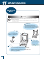
11 MAINTENANCE
Maintaining the Balance . . . . . . . . . . . . . . . . . . . . . . . . . . . . . . . . . . 124
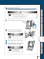
■ Removing the Glass Door . . . . . . . . . . . . . . . . . . . . . . . . . . . . . . . . . . . . . . . . . . . . . 125
Inspection . . . . . . . . . . . . . . . . . . . . . . . . . . . . . . . . . . . . . . . . . . . . . 126
TROUBLESHOOTING
■ Daily Inspections . . . . . . . . . . . . . . . . . . . . . . . . . . . . . . . . . . . . . . . . . . . . . . . . . . . . 126
■ Periodic Inspections. . . . . . . . . . . . . . . . . . . . . . . . . . . . . . . . . . . . . . . . . . . . . . . . . . 127
About Weights. . . . . . . . . . . . . . . . . . . . . . . . . . . . . . . . . . . . . . . . . . 128
■ Types of Weight and Their Selection. . . . . . . . . . . . . . . . . . . . . . . . . . . . . . . . . . . . . 128
130
FOR YOUR
INFORMATION
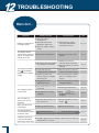
12 TROUBLESHOOTING
What to Do If….. . . . . . . . . . . . . . . . . . . . . . . . . . . . . . . . . . . . . . . . . 130
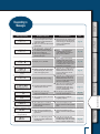
Responding to Messages . . . . . . . . . . . . . . . . . . . . . . . . . . . . . . . . . 131
15
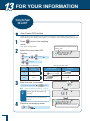
13 FOR YOUR INFORMATION
132
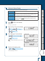
Turning the Power ON and OFF . . . . . . . . . . . . . . . . . . . . . . . . . . . . 132
■ Auto Power-Off Function. . . . . . . . . . . . . . . . . . . . . . . . . . . . . . . . . . . . . . . . . . . . . . 132
■ Setting the Startup Display . . . . . . . . . . . . . . . . . . . . . . . . . . . . . . . . . . . . . . . . . . . . 133
Changing the Password. . . . . . . . . . . . . . . . . . . . . . . . . . . . . . . . . . . 134
GLP Output Function. . . . . . . . . . . . . . . . . . . . . . . . . . . . . . . . . . . . . 135
■ Setting the GLP Output Function. . . . . . . . . . . . . . . . . . . . . . . . . . . . . . . . . . . . . . . . 135
■ Setting a Balance ID . . . . . . . . . . . . . . . . . . . . . . . . . . . . . . . . . . . . . . . . . . . . . . . . . 137
Specifications . . . . . . . . . . . . . . . . . . . . . . . . . . . . . . . . . . . . . . . . . . 138
■ ATX/ATY Series. . . . . . . . . . . . . . . . . . . . . . . . . . . . . . . . . . . . . . . . . . . . . . . . . . . . . 138
Maintenance Parts. . . . . . . . . . . . . . . . . . . . . . . . . . . . . . . . . . . . . . 140
■ ATX/ATY Series. . . . . . . . . . . . . . . . . . . . . . . . . . . . . . . . . . . . . . . . . . . . . . . . . . . . . 140
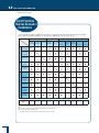
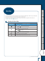
Menu Map. . . . . . . . . . . . . . . . . . . . . . . . . . . . . . . . . . . . . . . . . . . . . 143
■ Reading the Menu Map. . . . . . . . . . . . . . . . . . . . . . . . . . . . . . . . . . . . . . . . . . . . . . . 143
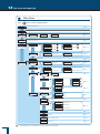
■ Main Menu. . . . . . . . . . . . . . . . . . . . . . . . . . . . . . . . . . . . . . . . . . . . . . . . . . . . . . . . . 144
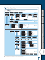
■ Data Output Menu. . . . . . . . . . . . . . . . . . . . . . . . . . . . . . . . . . . . . . . . . . . . . . . . . . . 145
■ Unit Setting Menu. . . . . . . . . . . . . . . . . . . . . . . . . . . . . . . . . . . . . . . . . . . . . . . . . . . . 146
■ Calibration Menu . . . . . . . . . . . . . . . . . . . . . . . . . . . . . . . . . . . . . . . . . . . . . . . . . . . . 146
■ Zero / Tare Menu. . . . . . . . . . . . . . . . . . . . . . . . . . . . . . . . . . . . . . . . . . . . . . . . . . . . 146
16
MEMO
BEFORE
WEIGHING
USING THE
BALANCE
USING MORE CONVENIENTLY
MAINTENANCE
TROUBLESHOOTING
FOR YOUR
INFORMATION
17
1 BEFORE WEIGHING
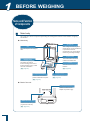
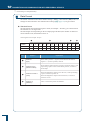
Name and Function of Components
n
Main body
The ATX/ATY Series comprises toploading electromagnetic balances with UniBloc weighing
mechanism.
Main body
Windbreak
Pan
Place the object to be weighed
here.
Even a slight breeze may affect
measurement, so the windbreak
is provided to avoid air
movements in the surroundings
influencing the weight reading.
Product label
Display panel
Shows the weighing results,
information for making
function settings, the current
function setting, errors, codes
and other information.
(^ page 20)
Operation keys
Used to tare the balance,
perform calibration and print.
(^ page 19)
The model name and serial
number are stated here.
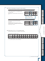
Level
Indicates the level of the
balance.
(^ page 24)
Level screws
Adjust to level the balance.
(^ page 24)
Back of the unit
DC IN connector
Used to connect an AC
adapter for power supply.
DATA I/O connector
Used to connect to a printer
(e.g. EP-80 or EP-90).
(^ page 118)
18
Operation keys
Symbol display
area
Numeric value /
menu display area
Unit display area
n
3
4
5
6
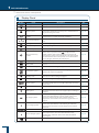
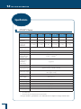
Operation Keys
During Weighing
Key
Press Once and Release ...
Press and Hold for About During Menu Operation
3 Seconds ...
•
•
1
[BREAK]
Switch between the operation
and standby modes
•
•
2
Enters the calibration menu
Tares the balance (setting it
[O/T] to zero)
Opens the zero / tare menu
•
•
4
[MENU]
•
•
•
In the weighing mode:
Opens the unit setting
menu
When piece counting: Used
to select the item number
When performing
percentage weighing:
Used to select the
percentage reference
Switches between the
Turns the smart setting mode
weighing mode and the
on
application function mode
Confirm and set
•
•
•
•
•
•
[PRINT]
•
Opens the data output menu
•
Scrolls forward through
menu options
When entering num
Takes you to a lower level
in the menu hierarchy
When entering
numerical values: Moves
the focus one digit on
the right
In the smart setting
mode: Adjusts to Stable
(S) direction.
FOR YOUR
INFORMATION
6
Outputs the weight reading to
a peripheral device (printer or
PC)
Scrolls backward
through menu options
When entering
numerical values:
Increases the value
In the smart setting
mode: Adjusts to
response (R) direction.
TROUBLESHOOTING
5
[UNIT]
In the weighing mode:
Used to select the unit
When piece counting:
Displays the unit weight
When performing
percentage weighing:
Displays the reference
weight
•
Takes you to a higher
level in the menu
hierarchy.
Long pressing the key
quits menu mode and
return directly to the
weighing mode.
Suspends calibration /
numerical value entry.
Quits the smart setting
mode.
MAINTENANCE
3
Performs calibration
[CAL]
USING MORE CONVENIENTLY
No.
2
WIN
USING THE
BALANCE
1
BEFORE
WEIGHING
AP
* Refer to P.90 for operations of each key during formulation/operation.
19
1
BEFORE WEIGHING
Name and Function of Components
n
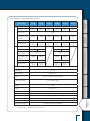
Display Panel
Display
20
Name
Description
See:
Battery symbol
Lights up when the battery voltage is low.
-
Zero tracking symbol
Lit when the zero tracking function is set ON.
Page 63
Weight symbol
This symbol is lit during calibration.
Blinks when calibration is necessary for a verified balance as
a legal measuring instrument.
Page 48
Automatic calibration
symbol
Blinks before automatic calibration starts applicable to a
verified balance as a legal measuring instrument.
Page 50
Easy setting indicator
Indicates what level the response and stability are currently
set to.
Page 70
Pouring symbol
Lit when the pouring mode is set.
Page 69
Formulation symbol
Lit during mixing measurement (formulation) operations.
Page 90
Menu lock symbol
Lit while the menu is locked.
Page 46
Menu operation key
symbol
Indicates that the menu option currently displayed requires
confirm and set operations when
is displayed in the
middle. Indicates that a higher or lower level exists in the
menu hierarchy when arcs are displayed on the right and left
side. Indicates that other menu options can be selected when
arcs on the upper and lower side is displayed.
Page 41
Auto print symbol
Lit when the auto print function is set.
Page 102
Win symbol
Lit when the WindowsDirect communication function has
been set.
Page 106
Communication symbol
Indicates that data is being exchanged with an external device.
-
Comparator symbol
When the comparator function (Checkweighing) has been set,
indicates the comparison judgment.
Page 96
Stability mark
Lit when the weight reading is stable. Lit when the option
currently set in menu setting is displayed.
Page 42
Page 72
Minus symbol
Lit when the weight reading is negative.
Ready symbol
Lit during the standby mode. During weighing, lit to indicate
the ready to weigh status, for example when using the mixing
measurement.
Page 39
Page 90
Number symbol
Lit when it is possible to enter numerical values.
Page 43
Hold symbol
Lit when a value that is not the real-time weight reading (for
example the indication of the unit weight in piece counting) is
displayed.
Page 84
Page 89
Net weight symbol
Indicates that the weight reading displayed in mixing
measurement (formulation) is the net weight of the current
component with the weight of the container and prior
components. Also indicates that a measuring operation is in
progress.
Page 91
Gross weight symbol
Indicates that the weight reading displayed in mixing
measurement (formulation) is the total weight of all of the
components of the mixture with the weight of the container
subtracted.
Page 91
Item number indication
Shows the item number in the piece counting mode.
Page 84
Inverse triangle symbol
When this symbol is lit when changing the position of the
decimal point in the conversion factor with the of userspecified units, numerical values can be entered without a
decimal point.
Page 44
Piece counting symbol
Lit while the piece counting mode is in effect.
Page 84
-
Display
Description
See:
Lit when the specific percentage reference has been set for
percentage weighing.
Page 96
Percentage weighing
symbol
Lit during percentage weighing.
Page 99
BEFORE
WEIGHING
n
Name
Specific percentage
weighing symbol
Numeric value area
Using a verified balance as a legal measuring instrument in the EU:
Model with EC Type Approval. Bracket appears at Scale Interval (d) digit as below.
USING THE
BALANCE
AP
WIN
USING MORE CONVENIENTLY
Bracket
MAINTENANCE
TROUBLESHOOTING
FOR YOUR
INFORMATION
21
1
BEFORE WEIGHING
Installation
n
Choosing the Installation Site
The measuring performance of the balance is greatly influenced by the environment where it is
installed.
Observe the following points to ensure safe and accurate weighing.
! Caution
Prohibitions
Do not use the balance anywhere exposed to explosive, combustible
or corrosive gases.
This could cause fire or trouble.
Instructions
Use the correct power supply and voltage with the balance.
Use the balance with the attached AC adapter.
Using an incorrect power supply or voltage with the balance will lead to fire or trouble
with the balance.
Note also that if the power supply or voltage is unstable or if the power supply capacity
is insufficient, it will not be possible to obtain satisfactory performance from the
balance.
Precautions on Use
Avoid locations where the balance will be exposed to any of the
following.
Prohibitions
You may not be able to obtain correct weight readings.
• Air flow from an air conditioner, ventilator, door or window
• Extreme temperature changes
• Vibration from surroundings or nearby equipment
• Direct sunlight
• Dust, fine particles, electromagnetic waves or a magnetic field
Install the balance on a strong and stable flat table or floor in the
room.
Instructions
22
Placing the balance in an unstable site could lead to injury or trouble with the balance.
When selecting the installation site, take into account the combined weight of the
balance and the item to be weighed.
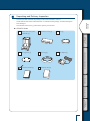
n
Unpacking and Delivery Inspection
BEFORE
WEIGHING
The items packed will differ depending on the model of balance ordered.
Check that all of the items indicated below are included in the package, and that nothing has
been damaged.
The numbers in the boxes [ ] indicate the quantity of each item.
ATX/ATY Series
Protective cover [1]
Pan [1]
Pan supporter [1]
Pan ring [1]
AC adaptor [1]
Instruction manual [1]
Menu map sheet [1]
USING THE
BALANCE
Balance main body (with
windbreak) [1]
USING MORE CONVENIENTLY
MAINTENANCE
TROUBLESHOOTING
FOR YOUR
INFORMATION
23
1
BEFORE WEIGHING
Installation
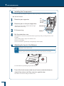
n
Installing the Components
The procedure for fitting the components differs depending on the model of the balance.
1
2
ATX/ATY Series
Place the pan supporter.
3
4
Place the pan on the pan supporters.
Align the two pan notches with the left and right
on the balance main body.
Fit the pan ring.
n
Pan
Pan supporter
Pan ring
Protective cover
Adhesive
Adhesive
Set the protective cover.
If the balance is used in an environment where it gets dirty easily, use the protective cover
available.
(1) Peel off the paper to expose the adhesive on it.
(2) Fit it on the display.
(3) Press the adhesive parts firmly to keep fitting it on the display.
Adjusting the Level of the Balance
*
Operation of the level screws
Turning the level screws clockwise, as viewed from above, extends them and raises the
balance, while turning them counterclockwise retracts them and lowers the balance.
Level
Level the balance by following the procedure below.
1
24
Turn all the level screws (total two at front) counterclockwise as
viewed from above until they come to a gentle stop.
The balance will now be tilting toward the front.
Adjust the two level screws at the front so that the air bubble in the
level becomes centered in the left/right direction.
At this stage it doesn't matter if the air bubble isn't centered in the front/rear direction.
If the air bubble is left of center
Turn the front right level screw clockwise.
Turn the front left level screw clockwise.
USING THE
BALANCE
If the air bubble is right of center
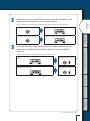
3
BEFORE
WEIGHING
2
USING MORE CONVENIENTLY
Turn both the level screws at the front in the same direction at the
same time to center the air bubble in the level in the front/back
direction.
Adjust so as to bring the air bubble into the center of the circle.
On turning the two level screws at the front in the clockwise
direction…
On turning the two level screws at the front in the
counterclockwise direction…
The bubble moves toward
the front.
The bubble moves toward
the back.
MAINTENANCE
TROUBLESHOOTING
FOR YOUR
INFORMATION
Continued on next page
25
1
BEFORE WEIGHING
Installation
n
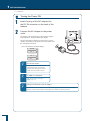
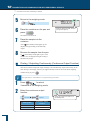
1
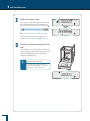
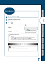
Turning the Power ON
Insert the plug of the AC adapter into
the DC IN connector on the back of the
balance.
2
Connect the AC adapter to the power
outlet.
The display will automatically go through the changes
indicated below, ending with the OFF display.
The first information displayed is the software version
number. Depending on the product, this may differ from
the example shown below.
(This is the balance's self check display.)
!1.0!0,0!0,0!0
...
! !C!H!E! !3
! !C!H!E! !0
! !O!F!F! !
*
*
For the ATX series…
An operation check on the internal
weight mechanism is performed
automatically. During this check, a
small motor noise will be heard.
If "ERR H" is displayed…
*
26
See "Responding to Messages"
(^ page 131).
Clamps are attached to the AC adaptor.
Fix the cable of the AC adaptor with clamps on an appropriate position on the back of the
balance so they do not interfere with the glass door when it is opened or closed.
n
Warming Up
BEFORE
WEIGHING
Before performing span calibration on the balance or measuring its accuracy, you must ensure
that it is in a stable state.
When stabilizing the balance, it is important that its temperature is stable.
Put the balance in weighing mode (for example showing the gram display) and leave it with the
power ON for at least an hour in advance of calibration.
This is called "warming up".
Warming up is also accomplished in the standby mode.
For details on the standby mode, see "Turning the Power OFF" (^ page 39).
USING THE
BALANCE
USING MORE CONVENIENTLY
MAINTENANCE
TROUBLESHOOTING
FOR YOUR
INFORMATION
Continued on next page
27
1
BEFORE WEIGHING
Installation
n
Performing Span Calibration
Always perform span calibration for a balance after moving it.
Weights are required for span calibration of the ATX series. For details on weights, see "About
Weights" (^ page 128).
Before performing span calibration, warm up the balance in advance.
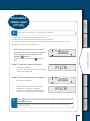
Also, carry out the adjustment at a location where there are few people moving around and there
is no air flow or vibration.
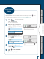
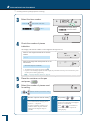
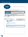
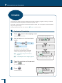
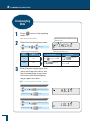
1
ATX Series
Press
Calibration using the internal weight starts
automatically.
*
! !C!A!L!3
If "WAIT" is displayed…
*
The calibration record is being output.
When output has finished, span
calibration will start automatically.
! !C!A!L!2
If "BUSY" is displayed…
There is something placed on the pan.
When this item is taken off the pan,
span calibration will start automatically.
! !C!A!L!1
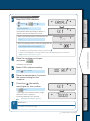
To cancel scan calibration, press
*
If "ERR H" is displayed…
*
See "Responding to Messages" (^
page 129).
! !C!A!L!0
If "ERR C" is displayed…
Span calibration was not completed for
one of the following reasons.
There is too large a discrepancy
between the zero point of the
balance and the sensitivity.
A container has been placed on the
pan.
The pan is not on the balance.
There is too large a discrepancy in
the value of the internal weight.
Press
! !W!A!I!T
* This may not
be displayed.
!E!N!D
and redo the operation from
the beginning. If even on doing this the
same display reappears, calibrate the
internal weight (^ page 56).
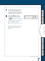
"END" will be displayed and the balance will return to the weighing mode.
28
Caution
BEFORE
WEIGHING
Instructions
If calibration doesn't end
normally and the balance
stops, do not move it nor
leave it as it is.
/ /
Press
2!0!0.0!0!0!0
USING MORE CONVENIENTLY
The weight value will flash.
*
/ //////
////
//
//
/////////
///
//
//
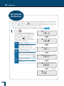
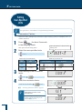
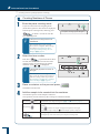
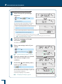
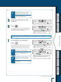
ATY Series
/ /
1
USING THE
BALANCE
Moving the balance in such a
condition may cause failure
because the internal weight is not
held correctly.
Before moving the balance, be
sure to turn the power on and start
it up correctly (so that the internal
weight is correctly held).
If "WAIT" is displayed…
*
The calibration record is being output.
When output has finished, span
calibration will start automatically.
If "BUSY" is displayed…
There is something placed on the pan.
Take the item off the pan and follow the
procedure below.
.
MAINTENANCE
To cancel scan calibration, press
*
If no operation is performed within
60 seconds…
Press
TROUBLESHOOTING
"ERR C" (calibration error) is displayed.
and repeat the operation
from the beginning.
FOR YOUR
INFORMATION
Continued on next page
29
BEFORE WEIGHING
2!0!0.0!0!0!0
(If necessary enter the weight value.)
For details on the weight values that can be
entered, see "Specifications" (^ page 138).
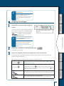
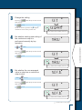
3
/ / / / / /
/ / / /
/ /
/ /
/ / /
1!9!9.9!9!9!8
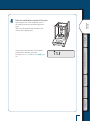
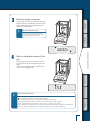
Place the calibration weight on the
pan.
Open the glass door in the windbreak, place the
weight on the pan, and shut the glass door again.
Wait until the flashing weight value display
changes to a flashing zero.
*
Shut the glass door fully.
After placing a weight on the pan or
removing a weight from the pan, check
that the glass door is fully shut.
//
/
//// /////
//
//
///
//
! !0.0!0!0!0
/////////
/
30
/ / /
^ "Entering Numerical Values", page 43
////
If necessary, change the weight value to match
the weight that will be used for calibration. If
there is no need to change it, proceed to step 3.
///
//
Enter the weight value.
//
2
////
/ / / / / /
/ / / /
/ /
/ /
///
1
Take the calibration weight off the pan.
Open the glass door in the windbreak, remove
the weight from the pan and shut the glass door
again.
"END" will be displayed and the balance will
return to the weighing mode.
BEFORE
WEIGHING
4
USING THE
BALANCE
!E!N!D
USING MORE CONVENIENTLY
The procedure described above is the default
standard span calibration procedure.
For details, see "4. CALIBRATION" (^ page
48).
MAINTENANCE
TROUBLESHOOTING
FOR YOUR
INFORMATION
31
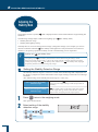
2 USING THE BALANCE
Weighing
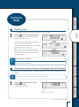
1
Enter the weighing mode.
What is the weighing mode?
The balance is in the state where it indicates the units (for example grams) of the weight on the
pan.
To establish the weighing mode, follow the steps below depending on the current status of the
balance.
Status of the Balance
The display is off.
"OFF" indication, all segments lit, or
(ready symbol) lit
To Establish the Weighing Mode….
Press
. When the "OFF" indication appears or all segments
are lit, press any key.
Press any key.
The application function mode is
established.
A menu indication is displayed.
Press
Press
a number of times. Or press
for about 3 seconds.
The balance is accepting numerical
value entry.
*
Press
See "Responding to Messages" (^ page 131).
2
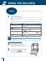
Place a container on the pan.
3
Once the display has stabilized (
Open the glass door in the windbreak, place the
container on the pan and shut the glass door again.
has lit), press
The indication changes to zero.
32
a number of times.
If an indication like "OL" or "-OL" appears during measurement…
With models that feature the windbreak
for about 3 seconds.
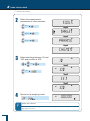
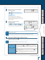
4
Insert the sample (item to be
measured) into the container.
BEFORE
WEIGHING
Open the glass door of the windbreak, place the
sample (item to be weighed) on the pan and shut
the glass door again.
5
*
Shut the glass door fully.
*
Avoid doing the following:
Check that the glass door is fully shut before reading the balance display.
USING MORE CONVENIENTLY
USING THE
BALANCE
When the display has stabilized,
(the stability mark) lights up, read
the display.
Putting your hand inside the glass door of the windbreak
Touching the container or sample with bare hands
Weighing samples (items to be weighed) of different temperatures
The heat will lead to convection, and this may make the balance display unstable.
Use forceps or gloves to carry containers and samples.
When dealing with samples (items to be weighed) at different temperatures, eliminate the temperature
difference by leaving the samples around the pan inside the glass door before weighing.
MAINTENANCE
TROUBLESHOOTING
FOR YOUR
INFORMATION
33
2
USING THE BALANCE
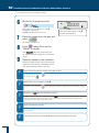
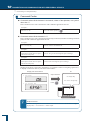
Outputting Weight
Readings
When the balance is connected to a PC and a printer (option), you can output a weight reading,
settings, and so on for each measurement. The WindowsDirect communication function (^
page 105) is convenient for output to a PC.
•
•
When the GLP output function (^ page 135) is set to OFF, only the weight reading is output.
When the GLP output function (^ page 135) is set to ON, the following information is output.
Example printout from printer
(When the GLP output function is set to ON)
Name of manufacturer
Balance model name
Balance serial number
Balance ID
Weight reading
The person who carried out
measurement signs here.
34
SHIMADZU CORP.
ATX224
D*********
200.0000g
n
BEFORE
WEIGHING
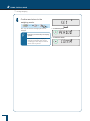
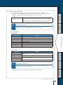
Selecting the Display
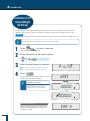
Switching Units
1
Press
in the weighing mode.
Repeatedly pressing this key will cycle you
through the registered units.
! !0.0!0!0!0
! ! ! ! !0.0
USING MORE CONVENIENTLY
When the balance is shipped from the factory,
the only unit registered is grams.
To be able to switch to other units, you must first
register the units you wish to use.
USING THE
BALANCE
You can display different units from among those set to be available.
^ "Selecting Units to Display", page 77
When user-specified units have been selected,
the characters and symbols that indicate the
units don't light up.
*
Unit display after restarting
When the power is turned off and back on, the balance starts up displaying the units that were in use
before the power was turned off.
MAINTENANCE
n
! ! 0.0!0!0
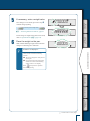
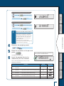
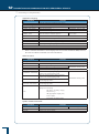
Selecting the Minimum Number of Displayed Digit (1d/10d display)
If necessary, the minimum number of displayed digit can be reduced by one digit (Set to the 10d
display).
1
Not applicable to a verified balance as a legal measuring instrument.
Press
twice shortly in the
weighing mode.
This opens the main menu.
TROUBLESHOOTING
*
STAND
FOR YOUR
INFORMATION
* This may not be displayed.
Continued on next page
35
2
USING THE BALANCE
Selecting the Display
2
Select the measurement
parameters in other functions.
! ! T!O!O!L!S
[TOOLS]
TAR!G!ET
[PARAM.W]
!P!A!R!A!M.W
[CHG.MIN]
! C!H!G.M!I!N
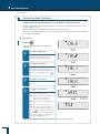
3
Select switching between 1D and
10D, and confirm at 10D.
1D!
[1D ]
[10D ]
10D! ! !
! S!E!T! !
10D! ! !
4
Return to the weighing mode.
or
*
36
! !0.0!0!0!0
Display after selection
The decimal place doesn't change. Note also that when one digit is removed the display area for the final
digit appears as a blank.
*
Follow the above steps, and confirm on the 10D display in step 4.
BEFORE
WEIGHING
n
To return to the 1d display...
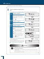
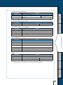
Selecting the Decimal Point Display Symbol
The decimal point can be displayed as either "." (a period) or "," (a comma).
Press
twice shortly in the
weighing mode.
STAND
This opens the main menu.
USING THE
BALANCE
1
* This may not be displayed.
2
Select decimal point display setting.
[TOOLS]
! !P!O!I!NT
[SYSTEM]
USING MORE CONVENIENTLY
[POINT]
3
Select the decimal point display
symbol.
To select "." (period):
[PERIOD]
To select "," (comma):
*
! !C!O!M!M!A
MAINTENANCE
[COMMA]
!P!E!R!I!O!D
TROUBLESHOOTING
When outputting to the ER-50/EP60A electronic printer (old type)…
Do not select "," (comma). The printer
may not print it correctly.
FOR YOUR
INFORMATION
Continued on next page
37
2
USING THE BALANCE
Ending Weighing
4
Confirm and return to the
weighing mode.
[SET]
The way the decimal is displayed has now
changed.
*
•
To select the period
!P!E!R!I!O!D
Selecting the decimal point display
symbol
When the decimal point display is
changed, the decimal point changes
accordingly in data output to external
devices such as printers.
38
! !S!E!T!
or
•
To select the comma
! !C!O!M!M!A
n
Turning the Power OFF
USING THE
BALANCE
1
2
BEFORE
WEIGHING
Ending Weighing
Establish the weighing mode.
^ "Weighing", page 32
Press
If the status described below is not established, press
USING MORE CONVENIENTLY
(the ready symbol) will light and the
standby mode will be established.
Normally, leave the balance on standby in this
state until the next weighing.
To shut the power off completely, disconnect the
AC adapter.
again.
The ready symbol lights up.
What is the standby mode?
This is the status in which the balance stands by, saving electricity although it can still be used
right away.
in the weighing mode the display is turned off,
(the ready
MAINTENANCE
On pressing
symbol) is lit and the power saving status (standby mode) is established.
During the standby mode, the interior of the balance is powered and in the warming-up status,
ready for immediate use.
TROUBLESHOOTING
! Caution
While [WAIT] or [SET] is displayed, on no account disconnect the AC
adaptor.
Prohibitions
There is a risk that data in the scale will be corrupted.
FOR YOUR
INFORMATION
39
3 MENU SETTINGS
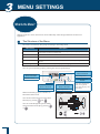
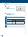
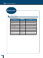
What Is the Menu?
With the ATX/ATY series, the menu is used to efficiently select the right functions for the user's
application.
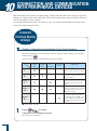
n
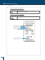
The Structure of the Menu
The menu is divided into five groups according to the setting made.
Menu Group
Description
Main menu
Used to set the application function mode, comparator, stability/response
adjustment and system configuration
Calibration menu
Used to set the details for calibration
Zero / tare menu
Used to set the details for taring and zero point
Data output menu
Used to set the functions for transmitting data to a PC or outputting them to a
printer
Unit setting menu
Used to set which units may be displayed in weighing mode
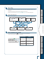
You can open each menu group by pressing the various operation keys.
AP
Press and hold for
about 3 seconds
WIN
Press and hold for
about 3 seconds
Unit setting menu
Calibration menu
Press once and
release
Press and hold for
about 3 seconds
Zero / tare menu
Within each menu group are a number of
Press once displays the
smart setting mode.
Press again displays the
main menu.
Press and hold for
about 3 seconds
Data output menu
Arrangement of the Menu
hierarchical menu levels.
COND.OUT
You can move between levels in the menu
hierarchy by pressing
RESET
and
You can scroll through the options within
SYSTEM
each level of the hierarchy by pressing
PERIOD
AUTO.OFF
or
BC.LIT
:
40
POINT
:
n
Menu Map
n
BEFORE
WEIGHING
The menu map represents the organization of the menu options graphically to make it easy to
understand.
It is useful for quickly accessing the menu option you want to use.
For more on the menu map, see "Menu Map" (^ page 143) and "Menu Map Sheet".
Instruction Manual
The instruction manual describes specific parts of the menu operations in a simplified form.
or
a number
to proceed
to the next menu
menu option.
option.
to
confirm.
Information displayed in
the menu display area
User
operations
Press
Flow of menu
operations
USING MORE CONVENIENTLY
Press
n
Press
of times to search for the next
USING THE
BALANCE
Press
a number
of times.
Menu Operation Key Symbol
On entering menu operation,
(the menu operation key mark) lights up.
The keys represented by lid segments can be used.
!0.0!0!0!0
The menu option
currently displayed
requires confirm and
set operations
Arcs on the right
and left side
A higher or lower level
exists in the menu
hierarchy
Arcs on the upper
and lower side
Other menu options can
be selected
TROUBLESHOOTING
Example of numeric value entry
in the middle
Meaning
MAINTENANCE
Displayed symbol
FOR YOUR
INFORMATION
41
3
MENU SETTINGS
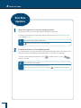
Basic Menu
Operations
1
Open the target menu from the weighing mode.
The method used to open a menu option differs depending on the group.
For details on the methods used for menu opening from each group, see "The Structure of the
Menu" (^ page 40).
*
2
For a menu option that is already set…
(the stability mark) appears in the menu display.
Confirm and return to the weighing mode.
The operation after confirming the menu selection differs depending on the menu, and you will
either be returned to the weighing mode automatically or will need to do it manually.
To return to the weighing mode manually, press
for about 3 seconds.
*
a number of times or press
If you open the menu again…
The recently set menu option will be displayed first.
Note also that, when the set menu option is displayed,
42
(the stability mark) also appears.
BEFORE
WEIGHING
Entering Numerical
Values
Numerical values sometimes have to be entered for menu settings, for example the weight value of a
calibration weight, condition values for operating functions, the balance ID, passwords, etc.
Operation Key
USING THE
BALANCE
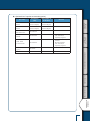
Operations of the operation keys
Operation During Numerical Value Entry
Confirms the entered numerical value
Increases the value of the digit to be entered (the flashing digit)
Pressing this key while the decimal point is flashing shifts the decimal point to the left.
Decreases the value of the digit to be entered (the flashing digit)
Pressing this key while the decimal point is flashing shifts the decimal point to the right.
USING MORE CONVENIENTLY
Shifts the digit to be entered (the flashing digit) one digit to the right
Cancels entry
n
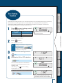
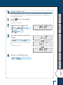
Changing the Numerical Value
As an example, here is the procedure for changing "120.0000 g" to "200.0000 g".
////
////
////
///
2!2!0.0!0!0!0
FOR YOUR
INFORMATION
The flashing shifts to the second digit from the
left.
!2!2!0.0!0!0!0
///
The numerical value of the flashing digit
increases by one, so that it changes from "1" to
"2".
TROUBLESHOOTING
3
Press
once.
////
Press
///
////
2
1!2!0.0!0!0!0
///
(the number symbol) lights and the leftmost
digit (highest digit) in the range where the value
can be changed flashes.
///
MAINTENANCE
Enter the numeric value entry
mode.
///
////
1
Continued on next page
43
MENU SETTINGS
Entering Numerical Values
5
Press
twice.
The numerical value of the second digit from
the left decreases two times, so that it changes
from "2" to "1" to "0".
2!0!0.0!0!0!0
Press
n
///
////
4
////
///
3
! !S!E!T! !
This confirms the entered numerical value.
The indication shown to the right remains
displayed for several seconds, then the display
automatically moves on to the next step.
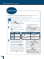
Changing the Position of the Decimal Point
The position of the decimal point can only be changed when entering a conversion factor with
the user-specified units.
^ "Conversion Factors", page 78
Establish the numeric value entry
mode.
(the number symbol) lights and the leftmost
digit (highest digit) in the range where entry
(change) is possible flashes.
1!0!0.0!0!0!0
///
//
several times.
This will move the decimal point to the left or
right.
*
1!0.0!0!0!0!0
///
//
or
//
Press
//
3
Press
several times until
the decimal point flashes.
//
1!0!0.0!0!0!0
//
2
///
///
////
1
////
As an example, here is the procedure for shifting the position of the decimal point one digit to
the left, to change the displayed value from "100.000" to "10.0000".
To set a numerical value with no
decimal point…
Press
several times until
(the
inverse triangle symbol) flashes.
4
44
Press
This confirms the entered numerical value.
The indication shown to the right remains
displayed for several seconds, then the display
automatically moves on to the next step.
! !S!E!T! !
n
BEFORE
WEIGHING
Convenient
Functions for Menu
Setting
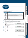
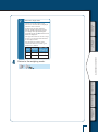
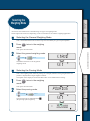
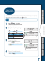
Returning to the Default Settings (Menu Reset)
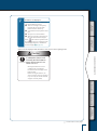
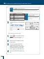
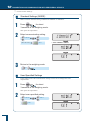
1
Press
twice shortly in the
weighing mode.
USING THE
BALANCE
If you want to return the menu settings to the default settings, reset the menu.
The default settings are indicated by asterisks in the menu map (^ page 144) and on the menu
map sheet.
! !ST!A!N!D
This opens the main menu.
[TOOLS]
[SYSTEM]
[RESET]
The password is set to "9999" before shipment.
If the default setting is not changed, enter
"9999".
///
MAINTENANCE
Enter the password.
! !O!K!?!
P!-! !0!0!0!0
////
3
[OK?]
! !R!E!S!E!T
////
Select menu reset.
///
USING MORE CONVENIENTLY
2
^ "Entering Numerical Values", page 43
TROUBLESHOOTING
^ "Changing the Password", page 134
4
Confirm.
[WAIT] [SET]
FOR YOUR
INFORMATION
The default menu settings are reinstated and
the balance automatically returns to weighing
mode.
! !W!A!I!T
! !S!E!T!
Continued on next page
45
3
MENU SETTINGS
Convenient Functions for Menu Setting
n
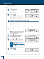
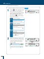
Prohibiting Changes to the Menu Settings (Menu Lock)
In order to ensure that the menu settings are not changed by mistake, the person managing the
balance controls the password and can prohibit menu operation.
The default password is "9999". To change the password, see "Changing the Password"
(^ page 134).
*
Operation in the menu lock status
Even when the menu is locked it is possible to perform calibration (
) and change the
weight value.
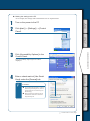
Press
until the display
changes (about three seconds)
while "OFF" is displayed after
supplying power or while in the
standby mode.
3
Enter the password.
^ "Entering Numerical Values", page 43
OFF display after supplying power
! !O!F!F
•
Standby mode
/ //
!P!-!0!0!0!0
////
2
•
////
/ //
1
Press
The password will be accepted.
The menu will be locked and the display will
return to the indication in step 1 .
! !L!O!C!K
The menu lock symbol will light up.
If the password is wrong…
4
The error message shown to the right will be
displayed and the display will return to the
indication in step 1.
Confirm.
On entering the weighing mode…
(the menu lock symbol) is shown in the
display.
On performing prohibited operations...
"LOCKED" is displayed and menu operation is
not possible.
46
! !E!R!R! !N
! ! !0!0!0!0
!L!O!C!K!E!D
*
To release the menu lock, perform steps 1 through 3 again.
BEFORE
WEIGHING
n
Releasing the menu lock
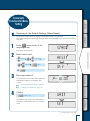
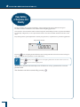
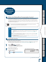
Outputting the Menu Setting Information
You can output the menu settings to make a record of the balance settings.
1
^ "10. CONNECTION AND
COMMUNICATION WITH
PERIPHERAL DEVICES", page 100
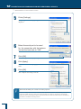
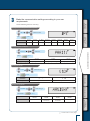
Press
twice shortly in the
weighing mode.
This opens the main menu.
Select output of menu setting information.
[TOOLS]
[SYSTEM]
[COND.OUT]
! ! !O!K!?
and return to the
MAINTENANCE
To cancel, press
weighing mode.
C!O!N!D.O!U!T
[OK?]
To output the settings, proceed to step 4.
4
! !ST!A!N!D
USING MORE CONVENIENTLY
2
3
USING THE
BALANCE
Connect the balance to a PC or
printer (option).
Confirm.
[WAIT]
During output the communication symbol is lit.
TROUBLESHOOTING
On confirmation, the menu setting information
is output to the PC or printer.
! ! !W!A!I!T
The balance automatically returns to weighing
mode.
SHIMADZU CORP.
ATX224
D*********
FOR YOUR
INFORMATION
47
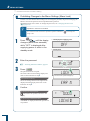
4 CALIBRATION
In order to weigh accurately with an electronic balance, the balance must be calibrated after it has been
moved or if the room temperature has changed substantially.
You are also advised to carry out calibration routinely (before use every day).
Before Starting
Calibration…
Following calibration operations are possible with the ATX/ATY series.
Span calibration
Adjust to achieve correct balance sensitivity using either the internal weight (ATX only)
or the external weight.
Drift in the sensitivity is corrected.
Registering the internal weight (ATX only) or the external weight on
by pressing
*
, you can start operations only
.
The operation to calibrate the internal weight itself cannot be registered in
To calibrate the internal weight itself, refer to "Calibration of the Internal Weight (ATX Only)"
(^ page 56).
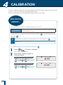
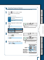
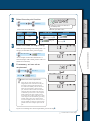
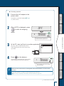
Use the following procedure to set the preferred operation for
1
2
Press
for about 3 seconds.
This opens the calibration menu.
Select either "internal weight" or
"external weight".
Example of registering "span calibration using the internal weight"
[CAL.EXE]
[I.CAL]
Example of registering "span calibration using the external weight"
[CAL.EXE]
48
[E.CAL]
! ! !I.C!A!L
! ! !E.C!A!L
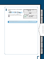
Confirm and return to the weighing
mode.
[SET]
Whichever was selected in step 2 is set for
and the balance returns to the weighing
mode.
! !S!E!T! !
or
•
BEFORE
WEIGHING
3
When "span calibration using the external weight"
has been selected
! ! !E.C!A!L
USING THE
BALANCE
When executing "span calibration", see "Span Calibration and Adjustment" (^ page 52).
USING MORE CONVENIENTLY
MAINTENANCE
TROUBLESHOOTING
FOR YOUR
INFORMATION
49
4
CALIBRATION
Automatic
calibration (ATX only)
*
Applicable to a verified balance as a legal measuring instrument.
Calibration with internal weight executes automatically in weighing mode under any of the
following circumstances.
(1)When there is a change in the surrounding temperature.
(2)When about four hours has passed since the previous calibration.
(3)After either condition (1) or (2) above has been met during warm up at stand-by status, when the
Case1) There is no load on the pan.
"PSC.RUN" is displayed and automatic span
adjustment is executed.
It returns to the weighing mode when automatic
span adjustment ends.
Case 2) There is some load on the pan.
When two minutes pass since mass display
blinking start, "PLS.CAL" is displayed.
If "PLS.CAL" is displayed, please unload the
thing on the pan and execute span adjustment.
!P!S!C.R!U!N
///// /////
//
! !0.0!0!0!0
/ /
Mass display will blinks.
*
//
blinking
/ /
When two minutes pass since
start,
! !0.0!0!0!0
//////////
//
///
//
When there is a change in the surrounding
temperature or about four hours has passed
since the previous span adjustment, the
indicator
will blink.
//
balance is switched to mass display mode.
!P!L!S.C!A!L
Push
key when you must keep measuring after “PLS.CAL” is displayed. Return to
blinking mass display.
If the span adjustment is not executed, the mass display blinking for two minutes and "PLS.CAL"
display are repeated.
50
*
BEFORE
WEIGHING
Announcement of
calibration request (ATY only)
Applicable to a verified balance as a legal measuring instrument.
USING THE
BALANCE
(1)When there is a change in the surrounding temperature.
(2)When about four hours has passed since the previous calibration.
(3)After either condition (1) or (2) above has been met during warm up at stand-by status, when
the balance is switched to mass display mode.
/ /
! !0.0!0!0!0
TROUBLESHOOTING
When two minutes pass since mass display
blinking start, "PLS.CAL" is displayed.
If "PLS.CAL" is displayed, please unload the
thing on the pan and execute span adjustment.
///// /////
//
/ /
Mass display will blinks.
MAINTENANCE
Case 2) There is some load on the pan.
!P!LS.C!A!L
//////////
//
"PLS.CAL" is displayed.
It returns to the weighing mode when calibration
with external weight ends.
!P!LS.C!A!L
Push
key when you must keep measuring after “PLS.CAL” is displayed. Return to
blinking mass display.
FOR YOUR
INFORMATION
//
blinking
Case1) There is no load on the pan.
*
//
When two minutes pass since
start,
! !0.0!0!0!0
USING MORE CONVENIENTLY
///
//
When there is a change in the surrounding
temperature or about four hours has passed
since the previous span adjustment, the
indicator
will blink.
If the span adjustment is not executed, the mass display blinking for two minutes and "PLS.CAL"
display are repeated.
51
4
CALIBRATION
Span Calibration
and Adjustment
Adjust to achieve correct balance sensitivity using either the internal weight (ATX only) or the external weight.
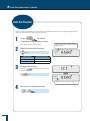
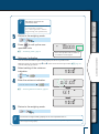
Set the relevant "span calibration" in
in advance by following the procedure in "Before Starting
Calibration …" (^ page 48). (As the default setting, "span calibration using the internal weight" is set
for ATX, and "span calibration using the external weight" is set for ATY.)
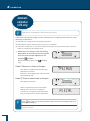
1
Span calibration using the internal weight (ATX series only)
I.CAL
Press
When the GLP output function (^ page
135) has been set to ON, initially the indication
"WAIT" is displayed, then the balance model
name and other information is output.
After a little while
(the weight symbol)
lights up and span calibration using the internal
weight will start automatically.
*
If "WAIT" is displayed…
*
If "BUSY" is displayed…
The calibration record is being output.
When output has finished, span
calibration will start automatically.
*
! !C!A!L!2
! !C!A!L!1
There is something placed on the pan.
When this item is taken off the pan, the
span calibration will start automatically.
To cancel the span calibration, press
! !C!A!L!3
If "ERR H" is displayed…
! !C!A!L!0
See "Responding to Messages" (^
page 131).
! !W!A!I!T
* This may not
be displayed.
!E!N!D
52
*
If "ERR C" is displayed…
BEFORE
WEIGHING
Span calibration was not completed for
one of the following reasons.
There is too large a discrepancy
between the zero point of the
balance and the sensitivity.
A container has been placed on the
pan.
The pan is not on the balance.
There is too large a discrepancy in
the value of the internal weight.
USING THE
BALANCE
Press
and redo the operation from
the beginning. If even on doing this the
same display reappears, calibrate the
internal weight (^ page 56).
"END" will be displayed and the balance will return to the weighing mode.
Caution
USING MORE CONVENIENTLY
Instructions
If calibration doesn't end
normally and the balance
stops, do not move it nor
leave it as it is.
Moving the balance in such a
condition may cause failure
because the internal weight is not
held correctly.
Before moving the balance, be
sure to turn the power on and start
it up correctly (so that the internal
weight is correctly held).
MAINTENANCE
TROUBLESHOOTING
FOR YOUR
INFORMATION
Continued on next page
53
CALIBRATION
Span Calibration and Adjustment
Span calibration using the external weight E.CAL
Press
When the GLP output function (^ page
135) has been set to ON, initially the indication
"WAIT" is displayed, then the balance model
name and other information is output.
After a little while
(the weight symbol)
lights up and the weight value of the weight to
be placed on the pan flashes.
*
If "WAIT" is displayed…
*
If "BUSY" is displayed…
2!0!0.0!0!0!0
The calibration record is being output.
When output has finished, span
calibration will start automatically.
There is something placed on the pan.
Take the item off the pan and follow the
procedure below.
To cancel scan calibration, press
*
// ///////
///
//
//
in the weighing mode.
/ //
1
/ / /
/////////
///
//
//
4
.
If no operation is performed within
60 seconds…
"ERR C" (calibration error) is displayed.
Press
and repeat the operation
For details on the range of weight values that
can be used, see "Specifications" (^ page
138).
54
/ / /
1!9!9.9!9!9!8
/ /
^ "Entering Numerical Values", page 43
// //////
///
//
//
/
(Enter a weight value if necessary.)
2!0!0.0!0!0!0
/////////
///
//
//
If necessary change the weight value displayed
to match the weight that will be used for
calibration. If there is no need to change it,
proceed to step 3.
///
///
Enter the calibration weight value.
////
2
////
from the beginning.
Place the weight on the pan.
Open the glass door in the windbreak, place the
weight on the pan, and shut the glass door again.
Wait until the flashing weight value display
changes to a flashing zero.
*
BEFORE
WEIGHING
3
\
Shut the glass door fully.
After placing a weight on the pan or
removing a weight from the pan, check
that the glass door is fully shut.
USING THE
BALANCE
//
/
//// /////
USING MORE CONVENIENTLY
//
///
/////////
/
//
4
//
! !0.0!0!0!0
Take the calibration weight off the
pan.
Open the glass door in the windbreak, remove
the weight from the pan and shut the glass door
again.
"END" will be displayed and the balance will
return to the weighing mode.
MAINTENANCE
*
TROUBLESHOOTING
!E!N!D
Avoid doing the following:
FOR YOUR
INFORMATION
Putting your hand inside the glass door of the windbreak
Touching the container or sample with bare hands
Weighing samples (items to be weighed) of different temperatures
The heat will lead to convection, and this may make the balance display unstable.
You are recommended to use forceps or gloves to carry containers and samples.
When dealing with samples (items to be weighed) at different temperatures, eliminate the temperature
difference by leaving the samples around the pan inside the glass door before weighing.
55
4
CALIBRATION
Calibration of the
Internal Weight (ATX Only)
In the ATX series, the weight for calibration is built in. The internal weight itself is calibrated on
shipment from the factory, but it is possible to recalibrate it using external weights. This is called
P.CAL
For the range of values for the external weights that can be used, refer to "Specifications" (^ page 138).
*
1
2
Press
Select calibration of the internal weight.
[P.CAL]
/ //
!P!-!0!0!0!0
^ "Entering Numerical Values", page 43
^ "Changing the Password", page 134
/ //
Press
W!A!I!T!
The password is acknowledged and the external
weight value for calibration flashes.
If "WAIT" is displayed…
The calibration record is being output.
When output has finished, span
calibration will start automatically.
! !0.0!0!0!0
If the password is wrong…
56
////////
///
//
//
/ / /
2!0!0.0!0!0!0
/ / /
////////
///
//
//
The error message shown to the right will be
displayed and the display will return to the
indication in step 1.
/ / /
////////
///
//
//
/ / /
*
////////
///
//
//
////
Enter the administrator’s password.
////
4
for about 3 seconds.
This opens the calibration menu.
3
Not applicable to a verified balance as a legal measuring instrument.
! !E!R!R! !N
////
2!0!0.0!0!0!0
///
/ / / / / / //
//
// /
/
//
(If necessary, enter a weight value.)
/ /
/ / /
! !0.0!0!0!0
/
/ / / / / / /
//
/
/ / / / / / /
//
/
If "ERR C" is displayed…
The internal weight has not been
calibrated for one of the following
reasons.
The wrong weight has been placed
on the pan.
No operation has been performed
within 60 seconds of the flashing
weight value or zero display.
Press
USING MORE CONVENIENTLY
*
/ / / / / / //
//
// /
/
//
Wait until the flashing weight value indication
changes to a flashing zero indication.
/
USING THE
BALANCE
Place the weight on the pan.
/ / /
6
For the range of weight values that can be used,
refer to "Specifications" (^ page 138).
1!9!9.9!9!9!8
/ /
^ "Entering Numerical Values", page 43
BEFORE
WEIGHING
If no change is to be made, proceed to step 6
without doing anything.
///
////
5
If necessary, enter a weight value.
and repeat the operation
from the beginning.
MAINTENANCE
TROUBLESHOOTING
FOR YOUR
INFORMATION
Continued on next page
57
4
CALIBRATION
Calibration of the Internal Weight (ATX Only)
7
Take the calibration weight off the
pan.
Open the glass door of the windbreak, take the weight off the pan, and close the glass door.
*
If "BUSY" is displayed…
!P!C!A!L!3
There is something placed on the pan.
When this item is taken off the pan,
internal weight calibration will start
automatically.
To cancel internal weight calibration,
!P!C!A!L!2
press
*
If "ERR H" is displayed…
*
If "ERR C" is displayed…
See "Responding to Messages" (^
page 131).
!P!C!A!L!1
The internal weight has not been
calibrated for one of the following
reasons.
There is too large a discrepancy
between the zero point of the
balance and the sensitivity.
A container has been placed on the
pan.
The pan is not on the balance.
There is too large a discrepancy in
the value of the internal weight.
Press
!P!C!A!L!0
CAL3 ~ CAL0 are performed.
! !W!A!I!T
and repeat the operation
from the beginning.
"END" is displayed, then span calibration using
the internal weight starts.
When span calibration using the internal weight
ends, the balance returns to the weighing mode.
^ "Span Calibration and Adjustment"
page 52
* This may not
be displayed.
!E!N!D
Caution
If calibration doesn't end normally and the balance stops, do not
move it nor leave it as it is.
Instructions
58
Moving the balance in such a condition may cause failure because the internal weight is
not held correctly.
Before moving the balance, be sure to turn the power on and start it up correctly (so that
the internal weight is correctly held).
BEFORE
WEIGHING
Leaving a Record of Calibration
You can leave a record of execution of calibration and set an ID for a balance to facilitate management of
multiple balances.
n
USING THE
BALANCE
Example Printout of a Calibration Record
You can output a record of execution of calibration to a PC or printer (option).
The WindowsDirect communication function (^ page 105) is useful for output to a PC.
The output calibration record includes the following items.
Example printout from printer
(When the GLP output function is set to ON)
USING MORE CONVENIENTLY
Type of calibration
Name of manufacturer
Balance model name
Balance serial number
Balance ID
Weight used
200.0000g
200.0001g
200.0000g
MAINTENANCE
Balance weight reading before
calibration (span calibration)
ATX224
D*********
Balance weight reading after
calibration (span calibration)
*
TROUBLESHOOTING
The person who carried out
the calibration signs here.
Outputting the date and time
FOR YOUR
INFORMATION
Since the ATX/ATY series doesn't incorporate a clock function, it is not possible to output the date and
time from the balance.
Continued on next page
59
4
CALIBRATION
Leaving a Record of Calibration
n
Setting Output of a Calibration Record
Output of the calibration record can be set by turning the GLP output function (^ page 135) ON and
OFF.
When the GLP output function is set to on, the statistic calculation function of the printer cannot be
used.
1
2
Press
for about 3 seconds.
This opens the calibration menu.
Select the GLP output function.
[GLP.OUT]
Stability Mark
3
Check the presence or absence of the
stability mark.
GLP Output Function
Lit
ON
Unlit
OFF
Change the setting.
Pressing
settings.
alternately sets the ON and OFF
!G!L!P.O!U!T
! !S!E!T! !
[SET]
!G!L!P.O!U!T
When ON is set the stability mark is lit.
4
60
Return to the weighing mode.
or
n
Setting a Balance ID
When managing multiple balances, you can set a four-digit management number (ID) for each
balance which will be indicated as part of calibration records output.
Press
mode.
BEFORE
WEIGHING
1
twice in the weighing
This opens the main menu.
Select setting of a balance ID.
[TOOLS]
[SYSTEM]
! !B!A!L.I!D
USING THE
BALANCE
2
^ "Entering Numerical Values", page 43
The default ID is "0000".
///
[SET]
! ! !0!0!0!0
USING MORE CONVENIENTLY
(Enter the ID.)
///
////
3
Enter the required numerals
(max. 4 digits).
////
[BAL.ID]
! !S!E!T! !
! !B!A!L.I!D
Return to the weighing mode.
MAINTENANCE
4
or
TROUBLESHOOTING
FOR YOUR
INFORMATION
61
5 FUNCTIONS RELATING TO TARING
The ATX/ATY series has the following functions relating to the zero point and taring.
Make use of these functions in accordance with the weighing environment and the application.
Zero / Taring Functions
Zero tracking function
Fluctuations in the zero point that occur
immediately after turning the power ON and as a
result of temperature changes are compensated
for, so the zero indication is maintained.
Auto zero function
Drift of the zero point that occurs as a result of
material left on the pan after measurement is
automatically compensated for.
See Hint
* as blow.
(^ page 63)
Auto tare function
After outputting a weight reading, taring is
executed automatically.
(^ page 64)
Zero / tare timing change function
After waiting for
(the stability mark) to light up,
zero point setting / taring is executed.
See Hint
* as blow.
(^ page 66)
(^ page 67)
What is taring?
This is a function whereby the weight of the container placed on the pan is subtracted to set the display to zero, so
that only the weight of the sample placed inside the container is indicated.
What is the zero point?
This means the state where nothing is placed on the pan, zero is indicated, and weighing can be started.
*
62
Not applicable to a verified balance as a legal measuring instrument.
BEFORE
WEIGHING
Zero Tracking
Function
1
Check (the zero tracking symbol)
in the weighing mode.
Zero Tracking
Symbol
ON
OFF
Press
twice.
This opens the main menu.
*
Setting from the zero / taring menu
You can also press
for about 3 seconds and make the setting
from the zero / taring menu.
Select the zero tracking function.
[Z.TRC]
Confirm the ON or OFF selection.
The ON or OFF status will be selected and
the balance will automatically return to the
weighing mode.
! !S!E!T! !
! !0!.!0!0!0!0
(the zero tracking
FOR YOUR
INFORMATION
After setting "ON",
symbol) lights up.
! ! !Z.T!R!C
TROUBLESHOOTING
[SET]
MAINTENANCE
4
Check the presence or absence of the
zero tracking symbol.
USING MORE CONVENIENTLY
Lit
Unlit
! !0!.!0!0!0!0
If you proceed to the next step while zero
tracking is ON, it goes OFF.
2
3
Zero Tracking Function
USING THE
BALANCE
When the zero tracking function is set, when the indication is zero (including when taring is performed)
the fluctuations in the zero point that occur immediately after turning the power ON and due to
temperature changes and other factors are compensated for and the zero indication is maintained.
(In the default setting the zero tracking function is ON.)
When the setting has been made from the zero / taring menu
or
! ! !Z.T!R!C
When the zero tracking function is ON,
the stability mark is lit in the menu display.
63
5
FUNCTIONS RELATING TO TARING
Auto Zero Function
When the auto zero function is set, any drift of the zero point that occurs as a result of material left on
the pan after weighing is automatically compensated for so that zero is displayed.
Note that the auto zero function cannot be used in combination with formulation.
*
1
Not applicable to a verified balance as a legal measuring instrument.
Press
for about
3 seconds in the weighing mode.
Check the presence or absence of
the stability mark.
Select the auto zero function.
! !A.Z!E!R!O
[A.ZERO]
What is the current situation?
Lit
ID is ON
Unlit
ID is OFF
To set or Update…
Press
Press
Press
and go to step 3.
and go to
step 4.
and go to
Go to step 4.
step 3.
Enter the value for the range for
automatic compensation to the
zero point (auto zero range).
(Enter the zero range value.)
To Cancel…
////
Auto Zero
Function
///
! !0.0!0!0!0
////
3
Stability
Mark
What do you want to do?
///
2
This opens the zero / taring menu.
[SET]
^ "Entering Numerical Values", page 43
If there is anything with a weight lower than or
equal to the auto zero range value left on the pan
after weighing the sample, it will automatically
be compensated for and the zero point will be
established when
(the stability mark) lights
up.
! !S!E!T! !
! !A.Z!E!R!O
When ON is set the stability mark is lit.
64
*
Auto zero range value
BEFORE
WEIGHING
The auto zero range value is only
effective in the units that are displayed
when the value is entered.
If other units are later selected,
change (update) the setting for the
zero range value by following the
procedure from step 1 while these new
units are displayed.
Minimum
Indication
Upper Limit
Value for the
Zero Range
g
0.0001 g
0.0099 g
ct
0.001 ct
0.099 ct
USING MORE CONVENIENTLY
4
Units
USING THE
BALANCE
The upper limit value for the zero range
is 99 d. 1 d is the minimum indication
in the displayed units.
For example, for a balance with a
minimum indication of 0.0001 g, the
situation is as follows.
Return to the weighing mode.
or
MAINTENANCE
TROUBLESHOOTING
FOR YOUR
INFORMATION
65
5
FUNCTIONS RELATING TO TARING
Auto Tare Function
When the auto tare function is set, the balance is automatically tared after the weight reading has been
output, and the indication at that point is set to zero.
1
Press
for about
3 seconds in the weighing mode.
This opens the zero / taring menu.
2
Select the auto tare function.
! !A.T!A!R!E
[A.TARE]
Stability Mark
3
Check the presence or absence of the
stability mark.
Auto Tare Function
Lit
ON
Unlit
OFF
Change the setting.
Pressing
OFF settings.
alternately sets the ON and
! !S!E!T! !
[SET]
! !A.T!A!R!E
When ON is set the stability mark is lit.
4
66
Return to the weighing mode.
or
BEFORE
WEIGHING
Zero / Tare Timing
Change Function
The zero / tare timing change function allows you to select whether setting of the zero point / taring is
executed without waiting for
(the stability mark) to light up, or after waiting for
(the stability
mark) to light up after pressing
USING THE
BALANCE
This function can also be applied to operations under the auto zero function and the auto tare function.
(The default setting is for execution without waiting for
*
Not applicable to a verified balance as a legal measuring instrument.
Press
for about
USING MORE CONVENIENTLY
1
(the stability mark) to light up.)
3 seconds in the weighing mode.
This opens the zero / taring menu.
2
Select the zero / tare timing
change function.
[TARE.F]
Stability
Mark
! ! !S!O!O!N
MAINTENANCE
The balance doesn't wait for
stability
Check the presence or absence of the
stability mark.
The balance waits for stability.
Unlit
Change the setting.
Pressing
alternately selects the
"wait for stability" and "don't wait for stability"
! !S!E!T! !
TROUBLESHOOTING
3
[SOON]
Zero / Tare Timing Change Function
Lit
! !T!A!R!E.F
settings.
[SET]
Return to the weighing mode.
FOR YOUR
INFORMATION
4
! ! !S!O!O!N
When "don't wait for stability" is
selected, the stability mark lights up.
or
67
6 ADJUSTING RESPONSE AND STABILITY
The response and stability of the balance can be adjusted in several ways in accordance with the
installation environment (degree of vibration and so on) and the weighing application (whether solid
objects / clumps or poured liquids / powders are being weighed).
•
•
Stability: The degree to which the weight reading is stable, with little fluctuation
Response: The speed of the reaction to changes in the weight on the pan
Set the optimum conditions for your application by following the procedure below.
Selecting the weighing mode
The ATX/ATY series offers two basic weighing modes.
Select the right one in advance in accordance with the environment of use and the application.
General weighing mode
Pouring mode
This is the fundamental mode in which
response and stability are given equal
emphasis.
This is a weighing mode where response is
given priority over stability, which is suited to
operations where substances like liquids or
powders are poured out until a target weight
is reached.
(^ page 69)
(^ page 69)
Adjusting the stability and response in real time during
weighing
Pressing
once in the weighing mode turns smart setting function on. By pressing
and
, you can adjust stability and response.
"Easy Setting of Response and Stability" (^ page 70)
Adjusting
(the stability mark)
The conditions for making
(the stability mark) light up (the stability detection range and the
stability mark lighting timing) can be adjusted.
"Adjusting the Stability Mark" (^ page 72)
68
BEFORE
WEIGHING
Selecting the
Weighing Mode
ATX/ATY series balances have the following two types of weighing mode.
Set the right mode in advance depending on the environment of use and the weighing application.
Selecting the General Weighing Mode
USING THE
BALANCE
n
This is the fundamental mode in which response and stability are given equal emphasis.
1
Press
mode.
This opens the main menu.
Select the general weighing mode.
[STAND]
[SET]
The balance has been set in the general
weighing mode.
n
USING MORE CONVENIENTLY
2
twice in the weighing
! !S!T!A!N!D
! !S!E!T! !
Selecting the Pouring Mode
1
Press
mode.
twice in the weighing
This opens the main menu.
Select the pouring mode.
[POURING]
TROUBLESHOOTING
2
MAINTENANCE
This is the weighing mode suited to pouring out a sample (substance being weighed such as a
powder or liquid) until a target weight is reached.
The update of the display is fast and the final value can be stabilized for reading.
P!O!U!R!I!N!G
[SET]
! !S!E!T! !
FOR YOUR
INFORMATION
The pouring mode is established and
(the pouring symbol) lights up.
! 0!.!0!0!0!0
69
6
ADJUSTING RESPONSE AND STABILITY
Easy Setting
of Response and
Stability
During weighing, the response and stability of the weighing mode can be adjusted in stages in
accordance with the installation environment and the weighing application.
The ATX/ATY series balances feature excellent response and stability, but since response and stability
are generally antagonistic, if one is prioritized it will to some extent weaken the characteristics of the
other.
Easy Setting allows quick adjustment to match your preference, requirements or particular application.
Easy setting indicator
! !0.0!0!0!0
Pressing
in the weighing mode flashes the smart setting indicator and turns the smart setting on.
Then, you can perform operations as in the table below.
*
Pressing
press
again (pressing
twice in the weighing mode) enters the main menu. In this case,
and return to the weighing mode.
Smart setting function automatically turns off if there is no key operation after a certain
period of time.
This functions can also be turned off by pressing
70
.
Priority Given to Response
Priority Given to Stability
BEFORE
WEIGHING
Easy setting
indicator
Press
•
•
•
When you want to weigh things quickly
When you want to improve working
efficiency
When weighing out target quantities of
a liquid or powder or when making a
formulation
Operation
The more times you press this key, the
further (the level indicator) moves to
the S side, increasing the stability of the
display in stages.
•
•
For these
circumstances…
•
When you want to weigh things with
confirmed accuracy
When the display is unstable
When the balance is used in a location
where there is a constant and relatively
large vibration
When the balance is subject to constant
air movements and the indication
wavers
USING MORE CONVENIENTLY
•
USING THE
BALANCE
The more times you press this key, the
further (the level indicator) moves to
the R side, increasing the response of the
display in stages.
Press
MAINTENANCE
TROUBLESHOOTING
FOR YOUR
INFORMATION
71
6
ADJUSTING RESPONSE AND STABILITY
Adjusting the
Stability Mark
The stability mark is a symbol (
stabilized.
) that is displayed when it is determined that the weight reading has
The following settings adjust conditions for lighting up of
(the stability mark).
Stability detection range
• Stability mark lighting timing
•
Normally there is no need to change these settings. (Change the settings if, for example, you want to
relax the conditions and make
(the stability mark) light more easily because the environment is
unstable, or to speed up operation if stability is used to automatically print or output data.
*
Lighting up of
The lighting up of
(the stability mark)
(the stability mark) indicates the fact that the weight reading is stable.
If the load is being changed slowly, or due to the settings relating to stability detection, the weight
reading may change while
(the stability mark) remains lit, or
(the stability mark) may light
temporarily and then the weight reading may change.
n
Setting the Stability Detection Range
The stability detection range is a value set as a count of the smallest digit that is displayed, and
the display is judged to be stable if fluctuation in the weight reading is within this count during a
fixed time.
(The default setting for the stability detection range is 1 count (1d).)
Effect of reducing the stability
detection range
Effect of increasing the stability
detection range
1
2
Press
(the stability mark) can be made to light more quickly
but the weight reading is liable to fluctuate after it has lit
(improvement of weighing and data output speeds).
twice in the weighing mode.
This opens the main menu.
Select setting of the stability
detection range.
[TOOLS]
[PARAM.W]
[BAND]
72
It takes some time for
(the stability mark) to light up, but
after it has lit the weight reading is stable (improvement in
reliability).
! ! !B!A!N!D
Select the value for the stability
detection range.
! ! ! !1!0!D
BEFORE
WEIGHING
3
(stability detection range that you
wish to select)
4
USING THE
BALANCE
Select the stability detection range from
among the following options depending on the
weighing application and purpose: 0.5d, 1d, 10d,
50d, 100d, 1000d.
Confirm and return to the
weighing mode.
! !S!E!T! !
or
[SET]
USING MORE CONVENIENTLY
The stability detection range has now been set.
! ! ! !1!0!D
Upon setting, the stability mark
lights up.
*
n
If data output is slow…
There are factors in the installation environment and the sample that make the display unstable. If data
output triggered by stability detection is very slow, increase the stability detection range.
MAINTENANCE
Setting the Stability Mark Lighting Timing
The timing according to which
(the stability mark) lights can be set in accordance with the
application and required accuracy.
*
Not applicable to a verified balance as a legal measuring instrument.
Effect of setting
the stability mark
lighting timing to the
standard setting
When stability is detected and remains detected for a fixed time,
(the
stability mark) lights up.
(the stability mark) lighting judgments become stricter and the weight
reading is stable after it has lit, so highly accurate weighing is possible
(improvement of reliability of data).
FOR YOUR
INFORMATION
At the same time as stability is detected,
(the stability mark) lights up.
The weight reading after
(the stability mark) lights up becomes more
susceptible to fluctuation since many samples can be weighed in succession
and the working time can be used more efficiently (improvement of weighing
speed).
TROUBLESHOOTING
Effect of speeding up
the timing for lighting
up of the stability
mark
Continued on next page
73
6
ADJUSTING RESPONSE AND STABILITY
Adjusting the Stability Mark
1
2
Press
twice in the weighing mode.
This opens the main menu.
Select setting of
(the stability
mark) lighting timing.
[TOOLS]
! !S!T!B.M!K
[PARAM.W]
[STB.MK]
3
Check the lighting timing setting.
[FAST]
! ! !F!A!S!T
Check the presence or absence of the
Stability
Mark
4
Stability Mark Lighting
Timing
Lit
Fast
Unlit
Standard
Change
(the stability mark)
lighting timing.
! !S!T!B.M!K
Pressing
alternately sets the "fast"
and "standard" settings.
[SET]
5
Return to the weighing mode.
74
! ! !F!A!S!T
When the timing is set to "fast" the
stability mark lights up.
or
MEMO
BEFORE
WEIGHING
USING THE
BALANCE
USING MORE CONVENIENTLY
MAINTENANCE
TROUBLESHOOTING
FOR YOUR
INFORMATION
75
7 SETTING UNITS
ATX/ATY series balances can be made to indicate weights in units other than the basic units of grams
by switching units with the
key in the weighing mode.
You must register the units you will require in advance.
On shipment from the factory, the only unit registered is g (grams).
^ "Switching Units", page 35
n
Units That Can Be Displayed and Conversion Factors
Some of the units below cannot be selected in some countries due to legal restrictions.
Weight Unit (Weight Name)
g (gram)
mg (miligram)
ct (carat) *3
mom (momme) *6
oz (ounce) *6
ozt (troy ounce) *6
dwt (pennyweight) *6
GN (grain) *6
HTI (Hong Kong tael) *6
Gram Conversion (*1)
Conversion Factor (*2)
1
1
0.001
1000
0.2
5
3.75
0.2666667
28.34955
0.035274
31.1035
0.0321507
1.55517
0.643015
0.064799
15.4324
37.429
0.0267173
STI (Singapore tael) *6
37.79936
0.0264554
TTI (Taiwan tael) *4, *6
37.5
0.0266667
37.79289
0.0264600
4.6083
0.216999
MTI (Malaysian tael) *6
m (mesghal) *6
o (parts pound)
B (baht) *6
S (sawaran) *6
Ks (kyats)
T (tola) *6
User *5, *6
*6
*6
0.88592
1.12877
15.2
0.0657895
7.999
0.1250156
16.606
0.0602191
11.664
0.0857339
Can be set as required by the user (*7)
*1 If we take the value in the Gram conversion column to be "a", the formula is as follows.
"a" × balance weight reading (each unit) = value in gram units
*2 If we take the conversion factor to be "k", the formula is as follows.
"k" × value in gram units = balance weight value (selected units)
*3 The minimum indication for ct (carat) may vary depending on the production lot even if they are the same model.
Not applicable to verified balance as a legal measuring instrument of ATX84 and ATY64.
*4 There are five kinds of Taiwan tael (TTL-1 to TTl-4).
The conversion factor is the same, but the minimum indication is as follows
TTl-1 A value 5 times that od TTl-2
TTl-2 The minimum value
TTl-3 A value twice that of TTl-2
TTl-4 A value 10 times that of TTl-2
*5 With user-specified units, the conversion factor (*2) and minimum indication can be set as required.
For details on the method for setting user-specified units, see "Setting User-Specified Units" (^ page 78).
*6 Not applicable to a verified balance as a legal measuring instrument.
76
BEFORE
WEIGHING
Selecting Units to
Display
Select and set the units you require to display so that they can be called up by pressing
weighing operation.
during
For details on user-specified units, see "Setting User-Specified Units" (^ page 78).
Press
USING THE
BALANCE
1
for about 3 seconds
in the weighing mode.
This opens the unit setting menu.
Select the units to be called up
and check if
(the stability mark)
is displayed or not.
Check the presence or absence
of the stability mark.
(Select the units.)
Stability Mark
Registering Units
Lit
ON
Unlit
OFF
Change the setting for units.
Pressing
OFF settings.
alternately sets the ON and
! !S!E!T! !
MAINTENANCE
3
!U!N!I!T!-
USING MORE CONVENIENTLY
2
[SET]
4
Return to the weighing mode.
!U!N!I!T!-
TROUBLESHOOTING
To set or cancel other units, go to step 2.
To quit, go to step 4.
When ON is set the stability mark
is lit.
or
Press
units.
FOR YOUR
INFORMATION
5
to call up selected
^ "Switching Units", page 35
77
7
SETTING UNITS
Setting User-Specified Units
*
n Conversion Factors
Not applicable to a verified balance as a legal measuring instrument.
Numerical values (multipliers) by which the weight reading (in grams) is multiplied can be set
without restriction.
1
Press
for about 3 seconds
in the weighing mode.
Check the presence or absence of the
stability mark.
This opens the unit setting menu.
2
Select the user-specified units.
!U!N!I!T!-!U!
[UNIT-U]
What is the current situation?
3
Stability
Mark
User-Specified
Units
Lit
Set
Unlit
Cancelled
What do you want to do?
To Set / Update
Press
To Cancel
and go to step 3.
Press
and go to step 3.
Go to step 5.
Select setting of the conversion
factor.
and go to step 5.
! !C!O!N!V.K
(Enter the conversion factor.)
[SET]
///
1!.0!0!0!0!0
///
Enter the conversion factor.
////
4
////
[CONV.K]
^ "Entering Numerical Values", page 43
*
78
Changing the position of the
decimal point
When entering a conversion factor, the
position of the decimal point can be
changed (^ page 44).
! !S!E!T! !
! !C!O!N!V.K
*
Calculation formula for the
conversion factor
BEFORE
WEIGHING
If we take the conversion factor to be
"k" the formula is as follows.
"k" × value in gram units = balance
weight reading (user-specified units)
5
Return to the weighing mode.
or
Press
to call up the userspecified units.
^ "Switching Units", page 35
n
USING THE
BALANCE
6
! !0.0!0!0!0
When user-specified units are called up,
no indication of units is given.
USING MORE CONVENIENTLY
Minimum Indication
You can set the minimum weight reading display for the user-specified units.
3
Make the setting by replacing steps 3 and 4 of the conversion factor procedure (^ page 78)
with the following procedure.
Select setting of the minimum
indication.
! ! !M!I!N.D
[SET]
!0.0!0!1!0!0
MAINTENANCE
(Enter the smallest indication.)
///
///
Enter the minimum indication.
////
4
////
[MIN.D]
^ "Entering Numerical Values", page 43
! !S!E!T! !
TROUBLESHOOTING
! ! !M!I!N.D
5
Return to the weighing mode.
*
FOR YOUR
INFORMATION
or
The minimum weight reading display for the user-specified units is ...
This can be set to any required value but in some cases it will not be possible to guarantee the stability
of the weight reading display.
79
8 APPLICATION FUNCTION MODE
Application Function Mode
You can choose one of the three modes indicated below to suit the application.
Percentage
weighing
Piece counting
You can set the unit weight
of the sample (item to be
weighed) and then "count"
the number of pieces
present.
(^ page 81)
*
You can measure weights
as a percentage of a
reference weight.
(^ page 86)
Formulation
This mode is convenient
when mixing a number of
different samples together
according to a formula.
(^ page 90)
When the application function mode is set…
Pressing
for 3 seconds alternately selects the weighing mode (gram or other unit indication) and
the application function mode in use.
It can be used in combination with the comparator function (^ page 96).
If the power is turned OFF and back ON the balance will start up in the weighing mode but the application
function mode settings will be retained.
Pressing
twice in the weighing mode displays the setting menu for each application function mode.
If you then press
or
, the top hierarchical level of the main menu appears.
The flow of the operation for displaying the menu is shown below.
Piece counting
Percentage weighing
Formulation
Press
Unit weight setting menu
5
Percentage reference
value setting menu
Component number and
gross weight setting menu
100 REF
ELM.NUM
etc.
100
Press
or
Displays the main menu.
STAND
TOOLS
80
TOTAL
BEFORE
WEIGHING
Counting
Pieces by Weight
(Piece Counting)
You can set the unit weight (weight of a single piece) of the item in advance and then display the number
of pieces in the sample.
USING THE
BALANCE
The unit weight is recorded by placing a sample on the pan that comprises the "number of pieces used for
setting".
Unit weights for up to five different types of items can be set at the same time.
*
Points where care is necessary
If the sample is spread out too much or unevenly in the container on the pan, accurate piece
counting will not be possible.
If a large quantity sample is to be weighed, and the quantity in the sample greatly exceeds the
quantity used to set the unit weight, there may be a large counting error.
USING MORE CONVENIENTLY
*
To minimize the counting error…
In step 5 of "Preparation for Piece Counting", make the number of pieces used for setting the
unit weight as large as possible.
When actually measuring numbers of pieces, don't place a large quantity of the sample on the pan
at one time but rather add a small portion at a time and, when the display has stabilized, press
for at least 3 seconds to update the unit weight. Keep repeating this operation.
n
Preparation for Piece Counting (Including Setting the Unit Weight)
1
Enter the weighing mode and
press
twice.
TROUBLESHOOTING
MAINTENANCE
The preparations for piece counting are explained here. Only make the setting in the following
circumstances.
• You are performing piece counting for the first time.
• You are switching from another application function mode to piece counting.
This opens the main menu.
Select piece counting.
[APL.FUNC]
[PCS]
! ! ! ! P!C!S
FOR YOUR
INFORMATION
2
[SET]
Continued on next page
81
8
APPLICATION FUNCTION MODE
Counting Pieces by Weight (Piece Counting)
3
Select the item number.
!S!A!M!P!L!E
(Item number: select from
[SAMPLE]
.)
Five different unit weight settings
(
) can be recorded.
[SET]
! !S!E!T!
4
Check the number of pieces
indication.
The display will indicate whether a unit weight has already been set.
When no unit weight has been set for the item
number:
[---]
When a unit weight has already been set for the
item number:
(The number of pieces is indicated.)
•
•
To update the unit weight, proceed to step 5.
If you are not intending to update the unit weight, the procedure from step 5 on is unnecessary. You
can start piece counting right away.
^""Counting Numbers of Pieces", page 84
5
6
Place the container on the pan
and press
Select the number of pieces used
for setting.
! ! ! ! ! !5
(Select the number of pieces used for setting.)
*
82
Number of pieces used for setting
The number of pieces used for setting
can be selected from among 5 pieces,
10 pieces …. 100 pieces.
In order to minimize counting error,
make the number of pieces used for
setting the unit weight as large as
possible.
*
On pressing
or
…
A menu option other than the number
of pieces for setting may be displayed
but this is not abnormal.
Press
or
several times to
return to the number of pieces for
setting display.
7
8
Check that
(the stability
mark) lights up, then confirm.
BEFORE
WEIGHING
Put a quantity of the item to be
counted corresponding to the
selected "number of pieces used
for setting" into the container.
! ! ! ! ! !5
USING THE
BALANCE
[SET]
The unit weight will be set and the number of
pieces of the sample will be indicated.
You can now start piece counting.
^ "Counting Numbers of Pieces", page 84
USING MORE CONVENIENTLY
If you wish to add the unit weight for another
item to be counted, see "Changing a Unit
Weight, or Adding a New Unit Weight"
(^ page 85).
MAINTENANCE
TROUBLESHOOTING
FOR YOUR
INFORMATION
Continued on next page
83
8
APPLICATION FUNCTION MODE
Counting Pieces by Weight (Piece Counting)
n
1
Counting Numbers of Pieces
Enter the piece counting mode
If you have returned to the weighing mode
(mode where grams or other units are displayed)
from the piece counting mode, then long press
for about 3 seconds to enter the
piece counting mode.
*
! ! ! ! ! !5
The piece counting symbol will light up.
If the piece counting mode is not
established…
The preparations for piece counting
have not been completed. Make settings
according to "Preparation for Piece
Counting (Including Setting the Unit
Weight)" (^ page 81).
2
Select the item number.
Each time
is pressed for about three
seconds, the selection moves to the next item
number and the corresponding item number
indication (from
to ) is displayed.
*
3
4
If the display appears as shown to
the right…
This means that the unit weight has not
been set for the selected item number. To
make this setting, follow the procedure
in "Changing a Unit Weight, or Adding a
New Unit Weight" (^ page 85).
! !-!-!-! !
Place a container on the pan and press
The balance will be tared.
Add the sample to be counted into the container.
The number of pieces in the sample is indicated.
The operations of each of the keys after setting are summarized below.
On pressing
twice.
On pressing
...
OOn long pressing
...
84
! ! ! ! !1!0
Establishes the unit weight setting menu. (^ step 3 onward on page 85.)
Pressing this key alternately displays the set unit weight (in grams) and the number
of pieces.
Press
while the unit weight is displayed to output the unit weight.
While the unit weight is displayed, (the hold display symbol) is displayed.
The weighing mode is established.
Pressing the key once more returns you to the piece counting mode.
n
Establish the piece counting mode.
In the weighing mode (mode where grams
or other units are displayed), long press
! ! ! ! ! !5
BEFORE
WEIGHING
1
Changing a Unit Weight, or Adding a New Unit Weight
to switch to the application
function mode.
Select the item number whose unit
weight you want to change, or for
which you want to add a unit
weight.
! !-!-!-! !
USING THE
BALANCE
2
Each time you press
for about 3 seconds,
the next item number is displayed.
^ "Counting Numbers of Pieces", page 84
USING MORE CONVENIENTLY
3
Place the container on the pan
and press
The balance will be tared.
4
Press
twice.
The number of pieces used for setting will be
displayed.
Select the number of pieces used
for setting.
! ! ! ! !1!0
MAINTENANCE
5
! ! ! ! ! !5
(Select the number of pieces used for setting.)
6
Check that
(the stability mark)
lights up, then confirm.
! ! ! ! !1!0
FOR YOUR
INFORMATION
7
TROUBLESHOOTING
Put a quantity of the item to be
counted corresponding to the
selected "number of pieces used
for setting" into the container.
[SET]
The unit weight will be added, and piece
counting will become possible.
85
8
APPLICATION FUNCTION MODE
Percentage
Weighing
In this mode the weight of the sample is converted to a percentage of the reference weight.
The following two setting methods are available for percentage weighing.
The reference weight is set as 100%.
100% Reference
Specific Percentage
Reference
n
1
The reference weight is set as a percentage value of your choice.
Preparation for Percentage Weighing
Press
mode.
twice in the weighing
This opens the main menu.
2
Select percentage weighing.
[APL.FUNC]
[PERCENT]
P!E!R!C!E!N!T
[SET]
The setting beyond this point differs depending
on the percentage value you are assigning to the
reference weight.
If the reference weight is being set as 100%, see "When setting the reference as 100%…" (^ page 87).
If the reference weight is being set as a specific percentage, see "When setting the reference as a
percentage of your choice…" (^ page 86).
86
When setting the reference as 100%…
Select the 100% reference.
[SAMPLE]
[SET]
!S!A!M!P!L!E
BEFORE
WEIGHING
3
(Check the indication.)
The indication differs depending on whether a
reference value has already been set or not.
! !S!E!T!
USING THE
BALANCE
When no percentage reference value has been set
[---]
When a percentage reference value has already been set
(The percentage reference value is displayed.)
•
4
To update the percentage reference value, proceed to step 4.
If you are not updating the percentage reference value, the following steps are not necessary.
^ "Weighing Percentages", page 89
Place the container on the pan
and press
The balance will be tared.
5
6
Select 100% reference setting.
Press
twice [100 REF]
1!0!0! !R!E!F
Place the sample that is to provide
the reference weight in the
container.
! !S!E!T!
TROUBLESHOOTING
Check that
(the stability
mark) lights up, then confirm.
MAINTENANCE
7
USING MORE CONVENIENTLY
•
[SET]
A percentage value with the reference weight
taken to be 100% is displayed.
Percentage Weighing is now possible.
! !1!0!0.0!0
*
FOR YOUR
INFORMATION
^ "Weighing Percentages", page 89
What to do if….
It is not possible to use a reference weight that weighs less than 100 times the minimum indication of
the balance as the reference weight.
Continued on next page
87
8
APPLICATION FUNCTION MODE
Percentage Weighing
When setting the reference as a percentage of your choice…
3
Select the specific percentage
reference.
[OPTION]
!O!P!T!I!O!N
[SET]
! !S!E!T!
(Check the indication.)
The indication differs depending on whether a
reference value has already been set or not.
When no percentage reference value has been set
[---]
When a percentage reference value has already been set
(The percentage reference value is displayed.)
•
•
4
To update the percentage reference value, proceed to step 4.
If you are not updating the percentage reference value, the following steps are not necessary.
^ "Weighing Percentages", page 89
Place the container on the pan
and press
The balance will be tared.
5
Enter a percentage value of your
choice.
[OPT REF]
O!P!T! !R!E!F
(Enter the percentage value.)
7
Check that
(the stability mark)
lights up, then confirm.
////
///
Place the sample that is to provide
the reference weight in the
container.
! ! !5!0.0!0
////
6
^ "Entering Numerical Values", page 43
///
O!P!T! !R!E!F
! !S!E!T!
[SET]
A percentage value calculated by conversion on
the basis that the reference weight is equal to the
set percentage is displayed.
Percentage weighing is now possible.
^ "Weighing Percentages", page 89
88
! ! !5!0.0!0
The specific percentage weighing symbol lights
up.
*
Weighing Percentages
Establish the percentage weighing
mode.
If you have returned to the weighing mode (mode
where grams or other units are displayed) from
the percentage weighing mode, then long press
! !1!0!0.0!0
USING THE
BALANCE
1
It is not possible to use a reference
weight such that the weight
corresponding to 100% is less than 100
times the minimum indication of the
balance.
BEFORE
WEIGHING
n
What to do if….
The percentage weighing symbol
lights up.
for about 3 seconds to enter the
percentage weighing mode.
If the percentage weighing mode
is not established…
The preparations for percentage
weighing have not been completed.
Make setting in accordance with
"Preparation for Percentage Weighing"
(^ page 86).
Place the container on the pan and press
The balance will be tared.
Insert the sample (item to be measured) into the container.
MAINTENANCE
2
3
USING MORE CONVENIENTLY
*
A percentage value obtained by conversion based on the set reference percentage value and
reference weight is displayed.
The operations of each of the keys after setting are summarized below.
twice.
The percentage reference value setting menu is displayed. (^ step 4
onward on pages 87 and 88.)
TROUBLESHOOTING
On pressing
The set reference weight (in grams) and the percentage indication are
On pressing
...
...
On long pressing
...
while the reference weight is displayed to
output the reference weight. While the reference weight is displayed,
hold display symbol) is displayed.
(the
FOR YOUR
INFORMATION
On long pressing
displayed alternately. Press
The 100% reference and specific percentage value are displayed alternately.
The mode is switched to the weighing mode.
Pressing the key again will return you to the percentage weighing mode.
89
8
APPLICATION FUNCTION MODE
Formulation
This function is useful when mixing multiple components together by weight, according to a formula.
Use this function while the printer is connected to a printer or PC.
The weight of each component is measured and output or added, and on completion of the formulation
the gross weight is output.
During formulation the auto zero function (^ page 64) will not work.
n
1
2
Performing Formulation
Press
twice in the weighing mode.
This opens the main menu.
The formulation symbol lights up.
Set the balance to the formulation
mode.
[APL.FUNC]
[FORMULA]
[SET]
The balance is now ready to weigh.
If necessary, set output of the component
numbers and output of the gross weight.
^ "Outputting Component Numbers",
page 93
^ "Outputting the Gross Weight", page 94
3
4
F!O!R!M!U!L!A
! !S!E!T!
! !0.0!0!0!0
The ready symbol lights up, indicating
that the balance is ready to weigh.
Place the container on the pan and
press
The balance will be tared.
Press
Formulation starts.
! !0.0!0!0!0
The ready symbol goes out.
90
*
When the GLP output function
(^ page 135) is set to ON…
5
Insert the component into the
container.
Press
The weight value of the current sample (item to
be weighed: element) is output / recorded and
the balance is automatically tared.
! !0.3!2!5!0
USING THE
BALANCE
6
BEFORE
WEIGHING
The balance ID (^ page 137) and
other information is printed.
! !0.0!0!0!0
The net weight symbol lights up.
USING MORE CONVENIENTLY
Now repeat the operations in steps 5 and 6 to add the other components to the formulation.
On completion of formulation,
press
.
Make the setting in "Outputting the
Gross Weight" (^ page 94) in
advance.
When the GLP output function
(^ page 135) is set to ON…
! !6.2!0!4!0
The ready symbol lights up, indicating
that the balance is ready to weigh.
TROUBLESHOOTING
*
To output the gross weight…
The gross weight symbol flashes.
MAINTENANCE
*
///
//
The total of the individual weight values up to
this point (gross weight) is displayed and the
balance returns to the ready to weigh status.
! !6.2!0!4!0
//
//
7
The signature panel is printed after the
total weight.
FOR YOUR
INFORMATION
Continued on next page
91
8
APPLICATION FUNCTION MODE
Formulation
The operation after setting is as follows.
When in the ready to weigh status:
On long pressing
...
The weighing mode is established.
Long pressing the key once more returns you to the ready to weigh status.
When weighing is in progress:
On pressing
...
The gross weight of the components weighed up to that point is displayed for
about 2 seconds.
Example printout from printer
(When the GLP output function is set to ON)
FORMULATION MODE
Name of manufacturer
Balance model name
Balance serial number
Balance ID
SHIMADZU CORP.
ATX224
D*********
CMP001=
0.9000g
CMP002=
1.2800g
CMP003=
9.6100g
TOTAL=
The person who carried out
measurement signs here.
92
11.7900g
n
Outputting Component Numbers
The numbers for each component are automatically assigned to the output results.
BEFORE
WEIGHING
1
Press
twice in ready to weigh
status while in the formulation
mode.
This opens the main menu.
*
USING THE
BALANCE
If the ready to weigh status is not
established…
Perform steps 1 and 2 of formulation
(^ page 86).
2
Select component number output
setting.
Stability Mark
Outputting Component
Numbers
Lit
ON
Unlit
OFF
Change the output setting.
Pressing
alternately sets ON and OFF
USING MORE CONVENIENTLY
Check the presence or absence of the
stability mark.
[ELM.NUM]
3
!E!L!M.N!U!M
! !S!E!T!
for the output setting.
Return to ready to weigh status.
!E!L!M.N!U!M
When ON is set the stability mark is
lit.
or
TROUBLESHOOTING
4
MAINTENANCE
[SET]
Weight reading for
each component
(output regardless
of the ON/OFF
status of component
number output)
FOR YOUR
INFORMATION
0.6280g
0.6280g
0.6810g
0.6680g
0.6590g
3.2640g
Component
number
Continued on next page
93
8
APPLICATION FUNCTION MODE
Formulation
n
Outputting the Gross Weight
The gross weight for a formulation weighing operation is output at the same time it is displayed.
The gross weight is output together with the printed indication: "TOTAL =".
1
Press
twice in ready to weigh
status while in the formulation
mode.
This opens the main menu.
*
If the ready to weigh status is not
established…
Perform steps 1 and 2 of formulation
(^ page 86).
2
3
Select gross weight output setting.
! !T!O!T!A!L
[TOTAL]
Stability Mark
Outputting the Gross
Weight
Lit
ON
Unlit
OFF
Check the presence or absence of the
stability mark.
Change the output setting.
Pressing
! !S!E!T!
alternately sets ON and OFF
for the output setting.
[SET]
4
Return to ready to weigh status.
or
! !T!O!T!A!L
When ON is set the stability mark is
lit.
Gross
weight
94
0.6280g
0.6280g
0.6810g
0.6680g
0.6590g
3.2640g
MEMO
BEFORE
WEIGHING
USING THE
BALANCE
USING MORE CONVENIENTLY
MAINTENANCE
TROUBLESHOOTING
FOR YOUR
INFORMATION
95
9 COMPARATOR FUNCTION
The comparator function performs a comparison between the weight reading and a reference value or
target value and displays the status of this comparison.
Comparator Function
You can select and use either of these modes according to the environment of use and application.
Target mode
Checkweighing mode
After setting a target value and a tolerance
range with respect to that target value,
excesses and deficits in relation to the target
value are indicated by
,
and
(the comparator symbols).
After setting the threshold values at the
upper and lower limits of the pass range,
when a sample is weighed a pass or fail
determination is indicated by
,
and
(the comparator symbols). An
out of range determination is indicated by all
comparator symbols OFF.
(^ page 96)
*
(^ page 98)
Before setting the comparator function
It can be used in combination with the application function mode (^ page 80).
If you are already using the application function mode, read "When the application function mode is set…"
(^ page 80).
The comparator function settings are retained even if the power is switched off.
Target Mode
1
2
Press
twice in the weighing mode.
This opens the main menu.
Check the presence or absence of the
stability mark.
Select the target mode.
[TOOLS]
! !T!A!R!G!T
[TARGT]
What is the current situation?
96
What do you want to do?
Stability
Mark
Target Mode
Lit
ON
Press
Unlit
OFF
Press
step 3.
To Set / Update
and go to step 3.
and go to
To Cancel
Press
step 4.
Go to step 4.
and go to
Enter the target value and the
tolerance range with respect to the
target value.
BEFORE
WEIGHING
3
^ "Entering Numerical Values", page 43
When entering the target value:
[TG.VAL]
USING THE
BALANCE
! !T!G.V!A!L
(Enter the target value.)
[SET]
When entering the tolerance range with
respect to the target value:
[LM.VAL]
USING MORE CONVENIENTLY
! !L!M.V!A!L
(Enter the tolerance range value.)
[SET]
4
Return to the weighing mode.
or
Place the container on the pan and
press
6
The balance will be tared.
Insert a sample into the container.
Condition
Over the target value range
Under the target value range
Judgment
Comparator Symbol
Large difference with respect to
the target value
(flashes slowly)
Small difference with respect to
the target value
(flashes quickly)
Acceptable
Small difference with respect to
the target value
(flashes quickly)
Large difference with respect to
the target value
(flashes slowly)
FOR YOUR
INFORMATION
Within the target value range
(target value ± permissible range)
1!0!5.0!0!0!0
TROUBLESHOOTING
Excess or deficiency is determined according to
the the following conditions.
The comparator symbols light in
accordance with the excess/deficiency
judgment.
MAINTENANCE
5
97
9 COMPARATOR FUNCTION
Checkweighing Mode
1
Press
mode.
twice in the weighing
This opens the main menu.
2
Check the presence or absence of the
stability mark.
Select the checkweighing mode.
[TOOLS]
What is the current situation?
3
!C!H!E!C!K.W
[CHECK.W]
What do you want to do?
Stability
Mark
Checkweighing
Mode
Lit
ON
Press
Unlit
OFF
Press
step 3.
To Set / Update
To Cancel
and go to step 3.
and go to
Press
step 4.
and go to
Go to step 4.
Enter the pass range upper limit
value and lower limit value, and
the checkweighing range lower
limit value and checkweighing
range upper limit value.
^ "Entering Numerical Values", page 43
To enter the pass range upper limit value:
[HI.LIM]
upper limit value.)
(Enter the pass range
! !H!I.L!I!M
[SET]
To enter the pass range lower limit value:
[LO..LIM]
lower limit value.)
98
(Enter the pass range
[SET]
! !L!O.L!I!M
To enter the checkweighing range lower limit value:
(Enter the checkweighing
[UND.RNG]
!U!N!D.R!N!G
BEFORE
WEIGHING
range lower limit value.)
[SET]
To enter the checkweighing range upper limit value:
(Enter the checkweighing
[OVR.RNG]
*
[SET]
Be sure to double check all values.
If the entered values don't go together
logically, for example if a value lower
than the lower limit value is entered as
the upper limit value, the values will
be automatically corrected and other
values will be set.
Particular care is required when
entering new values where settings have
been made before (updating).
USING MORE CONVENIENTLY
4
!O!V!R.R!N!G
USING THE
BALANCE
range upper limit value.)
Return to the weighing mode.
or
Place the container on the pan and
press
6
The balance will be tared
The comparator symbols light in accordance
with the pass or fail determination.
Insert the sample (item to be
measured) into the container.
MAINTENANCE
5
1!0!5.0!0!0!0
Condition
Upper limit value of the checkweighing range
< indication
Upper limit value of the pass range
< indication ≤ upper limit value of the checkweighing range
Result
Comparator
Symbol
Out of Range
All off
HI
PASS
Lower limit value of the checkweighing range
≤ indication < lower limit value of the pass range
LO
indication < lower limit value of the checkweighing range
Out of Range
FOR YOUR
INFORMATION
Lower limit value of the pass range
≤ indication
≤ upper limit value of the pass range
TROUBLESHOOTING
Pass or fail determination is based on the
following conditions.
All off
99
10 WITH PERIPHERAL DEVICES
CONNECTION AND COMMUNICATION
With ATX/ATY series balances, weight readings, settings and other data can be output to a personal
computer or a printer. This section describes some convenient functions relating to output, and how to
connect the balance to a PC or printer.
Use an optional dedicated printer. To connect to a PC, you need the optional RS-232 interface IFB102A-UNC and the RS-232C cable.
Convenient
Functions Relating to Output
n
Printing / Outputting Automatically (Auto Print Function)
This function allows you to automatically output the displayed weight reading at each weighing
without pressing
Select the output timing from among the following five modes.
Stable
Positive
Value
Stable
Negative
Value
Stable
Zero
Indication
Mode 1
When stability is detected with
a positive or negative value, the
value is output.
Mode 2
L!D.U!L.
When stability is detected with a
positive value, or when the reading
has returned to zero, the value is
output.
Mode 3
L!D. ! .Z
When stability is detected with a
positive or negative value or when
the reading has returned to zero,
the value is output.
Mode 4
L!D.U!L.Z
When the auto print function
is used in combination with the
checkweighing mode (^ page
98) and stability is detected with
an "OK" determination, the value
is output.
Mode 5
L!D.O!K.
: Output, Blank: Not output
Press
for about
3 seconds in the weighing mode.
This opens the output menu.
100
Explanation
When stability is detected with a
positive value, the value is output.
L!D.! ! .
1
Pass in
Checkweighing
Mode
Select the auto print function.
[APL.PRN]
A!U!T!O.P!R!N
[AUTO.PRN]
BEFORE
WEIGHING
2
Check the presence or absence of
the stability mark.
What is the current situation?
Auto Print
Function
Lit
ON
Press
Unlit
OFF
Press
step 3.
and go to
Go to step 5.
[SET]
! !S!E!T!
As an example, assume here that mode 3 is
selected (output with a stable positive value or a
stable zero indication).
If necessary, set zero return
requirement.
! ! !Z.R!E!T
[RET. 0] or
•
[SET]
What is zero return requirement?
! !R!E!T. !0
! !S!E!T!
TROUBLESHOOTING
FOR YOUR
INFORMATION
After the previous sample (item to be
weighed) has been removed from the pan,
the weight reading must fall below the
zero value and stability must be achieved
before the next sample is placed on the
pan, otherwise there will be no automatic
output for this next sample. This function
is intended to prevent two or more outputs
being made for the same sample. For the
zero return value, select either zero or 50%
of the weight of the immediately preceding
sample. Setting 50% saves time because
even if the display doesn't return to zero, as
long as stability is achieved, output will be
possible if the next sample is placed on the
pan.
When "RET. 0" is set:
MAINTENANCE
[RET. 50]
and go to
! !L!D. ! .Z
Select the output timing from among mode 1 to
mode 5 (see the table on the previous page).
[Z.RET]
Press
step 5.
USING MORE CONVENIENTLY
To Cancel
and go to step 3.
Select the mode for output timing.
(Select the mode.)
4
To Set / Update
USING THE
BALANCE
3
What do you want to do?
Stability
Mark
If you are not setting zero return requirement, proceed to step 5.
Continued on next page
101
10
CONNECTION AND COMMUNICATION WITH PERIPHERAL DEVICES
Convenient Functions Relating to Output
5
Return to the weighing mode.
! !0.0!0!0!0
or
6
Place the container on the pan and
press
When the setting is made, the auto
print symbol lights up.
The balance will be tared.
7
Place the sample into the
container.
After
(the stability mark) lights up, the
displayed weight reading is automatically
output.
8
Remove the sample from the pan.
If
(the stability mark) lights up at a value
close to zero, the displayed weight reading is
automatically output.
n
Printing / Outputting Continuously (Continuous Output Function)
This function allows displayed weight readings to be automatically output continuously in the
same timing as the display refresh cycle (approximately 100 msec intervals) while weighing,
without having to press
*
1
2
Not applicable to a verified balance as a legal measuring instrument.
Press
for about
3 seconds in the weighing mode.
Select the continuous output
function.
[APL.PRN]
Stability Mark
102
[SEQ.PRN]
Continuous Output
Function
Lit
ON
Unlit
OFF
!S!E!Q.P!R!N
Check the presence or absence of
the stability mark.
Change the setting.
Pressing
OFF settings.
alternately sets the ON and
! !S!E!T! !
BEFORE
WEIGHING
3
[SET]
If OFF is selected, perform step 6. Steps 7
onward are not necessary in this case.
!S!E!Q.P!R!N
When ON is set the stability mark is lit.
Set whether starting and ending of
the continuous output is
performed manually by key
operation.
USING THE
BALANCE
4
! !M!A!N!U!
Pressing
OFF settings.
USING MORE CONVENIENTLY
[MANU]
alternately sets the ON and
! !S!E!T! !
[SET]
! !M!A!N!U!
When ON is set the stability mark is lit.
Set whether the non-averaged
value is output as a continuous
output value.
[MANU]
MAINTENANCE
5
! !N!O!.!F!I!L
[NO.FIL]
[SET]
TROUBLESHOOTING
Pressing
OFF settings.
alternately sets the ON and
! !S!E!T! !
FOR YOUR
INFORMATION
! !N!O!.!F!I!L
When ON is set the stability mark is lit.
Continued on next page
103
10
CONNECTION AND COMMUNICATION WITH PERIPHERAL DEVICES
Convenient Functions Relating to Output
6
Return to the weighing mode.
! !0.0!0!0!0
or
When OFF is set for "MANU" in step 4,
continuous output starts.
Step 8 is not necessary in this case.
7
When ON is set for "MANU" in step 4,
the ready symbol lights up.
Place the container on the pan and
press
The balance will be tared.
8
Press
(when ON is set for
"MANU" in step 4).
After
(the ready symbol) has gone
off, displayed weight readings are continuously
output.
9
Place the sample in the container.
Displayed weight readings will be automatically
output in the same timing as the display refresh
cycle (approximately 100 msec intervals).
*
Pausing and restarting the continuous output function
To pause the function, press
.
To restart it, press
*
When OFF is set for "MANU" in step 4…
"MANU" is set to ON when
is pressed and the continuous output function is temporarily stopped.
*
Operation of
*
When connected to a printer…
(the communication symbol)
During continuous output, it may appear as though
(the communication symbol) is continuously lit.
Note also that if the transmission speed for data output is slow the display will be unstable and the
response time of the balance will also be slow.
For reasons linked to the performance of the printer, the data output interval will increase to longer
than 100 msec.
*
104
This function cannot be used with Windows Direct Communication Function.
n
BEFORE
WEIGHING
WindowsDirect
Communication
Function
What Is the WindowsDirect Communication Function?
USING THE
BALANCE
In any Windows application (e.g. Excel or the weight input window of an analytical device),
the numerical value displayed at the balance can be transferred to the cursor position just as if
it had been entered from the keyboard. The main body of the balance has a keyboard function,
so communication software is not required. As long as the status allows key entry, data can be
directly sent to the target device.
To connect to a PC, the optional RS-232C Interface IFB-103A-UNC (P/N321-41167-20) and
RS-232 Cable (P/N321-60754-01) are separately required.
What to do if…
After installing communications software in the PC and attempting communications, it
is not possible to use the WindowsDirect communication function even though the OS is
Windows.
Refer to communications setting as described in "User-Specified Settings" (^ page
120).
To control the balance from a PC, you must use command codes for programming (^
page 114), not the WindowsDirect function.
A dedicated tool is required in order to run the WindowsDirect communication function
with Windows Vista.
For details, contact your Shimadzu representative.
Setting the Function
MAINTENANCE
n
USING MORE CONVENIENTLY
*
Making the settings at the balance
When this setting is made, all of the communications settings are changed to those appropriate
for WindowsDirect communication. See "Communication Settings" (^ page 119).
Press
for about
TROUBLESHOOTING
1
3 seconds in the weighing mode.
2
This opens the output menu.
Select WindowsDirect
communication.
(Select the output data format.)
When "WIN|" has been selected:
! ! !W!I!N!|
FOR YOUR
INFORMATION
[WINI]
•
Continued on next page
105
10
CONNECTION AND COMMUNICATION WITH PERIPHERAL DEVICES
WindowsDirect Communication Function
*
When
(the stability mark) is lit up…
The output data format has already been set. If you proceed to the next step in this status the
setting will be cancelled and the balance will return to the status immediately before setting.
There are four types of output data format.
Indication
3
Output Data Format
WIN|
Numerical value + (ESC) + [enter.]
WIN|.U
Numerical value, unit symbol
(ESC) + [enter.]
WIN-
Numerical value + (ESC) + [tab.]
WIN-.U
Numerical value, unit symbol
+ (ESC) + [tab.]
Confirm and return to the weighing
mode.
Connecting the RS-232C cable
1
Press
in the weighing mode.
(the ready symbol) will light up and
the standby mode will be established.
Remove the AC adapter from the
power outlet.
Connect the optional RS-232
interface IFB-102A-UNC to the
DATA I/O connector on the rear of
the balance and connect the RS232C cable to the IFB-102A-UNC.
106
If you have selected a format with
[ENTER] appended…
In some Windows applications, ENTER
may cause the current window to close.
If this is the case, select a format with
[Tab] appended.
! !S!E!T!
or
This completes the setting procedure at the
balance.
When the function is set,
(the Win symbol)
lights up.
4
(ESC) : It means Escape sequence and describe "0x1b" in ASCII code.
[SET]
2
3
*
Connect the RS-232C cable to the
PC.
! !0.0!0!0!0
Making the settings at the PC
As an example, the settings made with Windows XP are explained here.
1
2
Turn on the power to the PC
BEFORE
WEIGHING
Click [start] (→ [Settings]) → [Control
Panel].
USING THE
BALANCE
Click [Accessibility Options] in the
Control Panel.
4
Enter a check mark at [Use Serial
Keys] under the [General] tab.
The [Accessibility Options] screen will be
displayed.
In addition…
If you find [Administrative options]
TROUBLESHOOTING
*
MAINTENANCE
USING MORE CONVENIENTLY
3
under the [General] tab too, enter a
check mark here as well as at [Use
Serial Keys].
Remove all check marks from all
checkboxes under tabs other than
the [General] tab.
FOR YOUR
INFORMATION
Continued on next page
107
10
CONNECTION AND COMMUNICATION WITH PERIPHERAL DEVICES
WindowsDirect Communication Function
5
Clicks [Settings].
The [Settings for SerialKeys] dialog box will be
displayed.
6
Select the serial port to be used
for the connection with the balance
and set the baud rate to "300".
7
8
Click [OK].
Return to the [Accessibility Options] window.
Click [Apply].
Wait a short time until the [Apply] character color
fades.
9
Click [OK].
This completes the settings at the PC.
*
108
When the RS-232C port is used for another purpose…
Once a serial key device has been activated, other software that uses the same RS-232C port will not
operate normally. If a device such as an external modem or a plotter is connected to the same RS232C port, after connecting the balance you must remove the check mark from the [Use Serial Keys]
checkbox to invalidate serial key devices.
Checking operation
1
BEFORE
WEIGHING
Connect the AC adapter to the
power outlet.
The balance's self check display (^ page
26) will be shown.
When [OFF] is displayed, press
to enter the weighing
USING THE
BALANCE
2
! !O!F!F
mode.
! !0.0!0!0!0
USING MORE CONVENIENTLY
Check if the Win symbol is lit.
At the PC, start up Excel (or another application such as Notepad).
Key entry will be enabled and the cursor
will be displayed at the position where entry
is possible.
! !0.0!0!0!0
///
///
on the balance.
The numerical value displayed on the balance
will be transferred to the cursor position.
MAINTENANCE
Press
//
4
///
3
TROUBLESHOOTING
Upon transfer, the communication
symbol will flash.
*
When the auto print function is used together with the WindowsDirect communication
function…
FOR YOUR
INFORMATION
Check that operation is normal even when using the auto print function.
^ "Printing / Outputting Automatically (Auto Print Function)", page 100
Continued on next page
109
10
CONNECTION AND COMMUNICATION WITH PERIPHERAL DEVICES
WindowsDirect Communication Function
n
Troubleshooting the WindowsDirect Communication Function
If the WindowsDirect communication function doesn't run properly, check the following points.
If this doesn't resolve the problem, contact your Shimadzu representative.
Q1
A1
WindowsDirect communication has been set but it is not operating at all.
Check the type of communications cable used for the connection (Shimadzu authorized part
or another part available on the general market) and the soundness of the connection.
If a USB serial converter is used, depending on the circumstances at the setup there is a
possibility that it has been automatically set to a COM port number higher than 4, and in
this case you should reassign it to a COM port number that can be used by serial key devices
(COM1 to COM4).
It is possible that the driver used as an accessory with the USB serial converter has not been
set up properly. Try uninstalling the driver and installing it again.
Some notebook PCs feature a setting for disabling RS-232C ports as a power-saving measure.
Before trying to use the WindowsDirect communication function, make the setting that
enables the use of RS-232C ports.
Communications with other applications and PCs via a LAN may interfere with the serial key
device settings. Try using WindowsDirect communication without using the LAN.
Q2
The WindowsDirect communication function won't work after I restart the PC.
A2
Some PCs don't recognize that a serial key device has been set when they start up. For details
on how to deal with this, contact your Shimadzu representative.
Q3
A3
I want to use the WindowsDirect communication function with Windows Vista.
Windows Vista doesn't have the serial device setting screen that is required to set the
WindowsDirect communication function. For details on the setting, contact your Shimadzu
representative.
Q4
A4
Data is input to the PC as garbled characters.
Either the balance or the PC is not set for the WindowsDirect connection function. Make the
settings again by referring to "Setting the Function" (^ page 105).
Q5
When data is input into Excel, the cursor doesn't move to another cell.
A5
If a function for conversion to 2-byte characters is available in Windows, turn the setting for
this function off.
Click the [Edit] tab under [Options] in Excel and check [Move selection after Enter] (if cells
move in response to keyboard input there is no problem).
Check the input data in another application (e.g. Notepad).
Q6
A6
The operation is sometimes abnormal.
Depending on the processing capability of the PC, malfunctions may occur if the
communications speed is high. Set 300 bps for the communication speed. Malfunctions may
also occur if the interval for data transmission from the balance is too short. Ensure that one
batch of data is displayed on the screen before the next batch of data is sent. And if there is
limited processing capability, don't use the continuous output function.
When data is sent from the balance, don't touch the PC's keyboard or mouse.
110
BEFORE
WEIGHING
Connecting to a PC
(RS-232C)
Caution
USING THE
BALANCE
To connect to a PC, the optional RS-232C Interface IFB-103A-UNC (P/N321-41167-20) and
RS-232 Cable (P/N321-60754-01) are separately required.
Use a correctly connected cable.
The connection method and special accessory RS-232C cable described below do not guarantee
normal operation with all types of PC.
Instructions
USING MORE CONVENIENTLY
When using the WindowsDirect communication function, see "WindowsDirect Communication
Function" (^ page 105).
n
Cable Connection Method
For IBM PC/AT, DOS/V, and AX PC (D-sub 9-pin) (Cross wire connection)
PC Side
2
2
TXD
TXD
3
3
RXD
DTR
4
6
DSR
SG
5
7
SG
DSR
6
20
DTR
RTS
7
5
CTS
CTS
8
4
RTS
TROUBLESHOOTING
RXD
MAINTENANCE
Balance Side
(RS-232C Interface)
FOR YOUR
INFORMATION
Continued on next page
111
10
CONNECTION AND COMMUNICATION WITH PERIPHERAL DEVICES
Connecting to a PC (RS-232C)
n
Data Format
The details of the data format when standard setting 1 (MODE.1 ) or data format 2 (DF.2 ) in the user
settings has been selected in the communication settings (^ page 119) are given below.
Standard format
The data format when outputting negative values (for example: -123.4567 g) is as shown below.
The delimiter is a carriage return.
The data length varies depending on the accompanying information, the number of characters
used to indicate units, the delimiter and so on.
Data length for this example: 12 bytes
1
Position
ASCII code
Data
No.
112
2
3
4
1
2
3
4
5
6
7
8
9
10
11
12
2DH
31H
32H
33H
2EH
34H
35H
36H
37H
67H
20H
0DH
-
1
2
3
.
4
5
6
7
g
Position
C/R
Explanation
1
Position 1
(sign)
If the value is positive " " (a space) is entered and if the value is
negative "-" (a minus symbol) is entered.
2
Positions 2 to 9
(absolute values)
If not all of the eight locations are used for a numerical value, a code
representing a space is entered at the blank positions, as shown in
the example.
3
Positions 10 and 11
(units)
If the unit designation comprises one character, a code representing
a space is entered at position 12.
If the unit designation comprises three characters, a total of 14
characters is sent.
4
Position 12
(delimiter)
This is a code that represents the delimiter.
When the data length is longer than the standard
When outputting data with stability information included
Position
ASCII code
Data
1
2
3
4
53H
2DH
20H
31H
S
-
BEFORE
WEIGHING
A code representing S or U is appended at the
head of the data.
Accordingly, the data length is increased by one
byte.
1
When stable: S (53H)
When unstable: U (55H)
USING THE
BALANCE
When the delimiter "C/R+L/F" is selected
Two bytes are required for the delimiter
information.
One byte is added after position 12 in the
standard format. Accordingly, the data length is
increased by one byte.
Position
ASCII code
Data
1
11
12
13
2DH
20H
0DH
0AH
C/R
L/F
-
USING MORE CONVENIENTLY
When there is "OL" or "-OL" (overload) output
The data format when "OL" is included is shown below.
Data length for this example: 12 bytes
Position
ASCII code
Data
1
20H
2
20H
3
4
5
20H
20H
20H
6
4FH
O
7
4CH
8
9
10
11
12
20H
20H
20H
20H
0DH
C/R
L
MAINTENANCE
When the information is "-OL" (minus overload), the entry at position 1 is changed from a space
to "-" (a minus symbol, ASCII code 2DH).
TROUBLESHOOTING
FOR YOUR
INFORMATION
Continued on next page
113
10
CONNECTION AND COMMUNICATION WITH PERIPHERAL DEVICES
Connecting to a PC (RS-232C)
n
Command Codes
Commands whose final character is a numeral, a letter of the alphabet, or a symbol
other than "="
Each command code is sent to the balance with a delimiter appended at the end
Example 1:
P R I N T (C / R)
This is the same as pressing
Commands whose final character is "="
Each command code is sent to the balance followed by numerals (sometimes including a decimal
point) and with a delimiter appended at the end.
Example 2:
ID = 1 2 3 4 (C / R)
This sets "1234" as the balance ID.
Example 3:
UW1 = 1 . 2 3 (C / R)
(Example for models with two places
after the decimal point)
This sets 1.23 g as the unit weight for piece counting 1.
Example 4:
UW1 = 0 . 0 0 (C / R)
(Example for models with two places
after the decimal point)
This clears the unit weight for piece counting 1.
Working from the PC connected to the balance, it is possible to instruct a weighing operation or
to display a numerical value of your choice at the balance.
Display panel of the balance
•
PC
"# = 2 . 5 6"
Output to the PC
"# = 1 2 . 3 4 5 . 6 7"
Press
"2 - 5 6 (C / R)"
"1 2 - 3 4 5 - 6 7 (C / R)"
•
*
114
Output to the PC
In order to distinguish between instruction information from the PC and the balance's weight
display data, "." is converted to "-" before output.
Echo-back commands
A character string comprising N characters following an echo-back command "{" or "}"
and terminated by a delimiter is resent unchanged from the balance (provided unprocessed
commands do not remain in the balance's receive buffer, and N ≤ 30).
BEFORE
WEIGHING
Example 5:
ABCDEFG12345
(C / R)
To print with the printer
USING THE
BALANCE
*
After receiving this command, the balance outputs A B C D E F G 1 2 3 4 5
(C/R).
When a printer is used in combination with the balance, this character string
can be printed by the printer (printing of any required character string).
Only use upper case letters of the alphabet, numerals and some symbols (including the
decimal point and signs), and limit the string to within 15 characters.
Command list
Data output
Command
Function
Continuous output *1
D02 *2
Continuous output at stability
D03 *2
Continuous output with stability information
D05
Single output
D06
Auto print setting
D07
Single output with stability information
D08
Single output at stability
D09
Cancel output
USING MORE CONVENIENTLY
D01 *2
*1 When handshake is OFF, output at a cycle around 100 msec.
Key operation
Command
Q
CAL
Function
MAINTENANCE
BREAK
Break key
Calibration key
TARE
T
PRINT
Output key
TROUBLESHOOTING
*
Zero setting / taring key
Acceptance of commands
Depending on the status of the balance, even though a command is output it may not be
accepted, with the display of "COM ERR".
FOR YOUR
INFORMATION
*2 Not applicable to a verified balance as a legal measuring instrument.
Continued on next page
115
10
CONNECTION AND COMMUNICATION WITH PERIPHERAL DEVICES
Connecting to a PC (RS-232C)
Application weighing
Command
Function
R
Piece counting
PCSo
UWo = XX.XXXX
UWo
Cancels application weighing mode setting
UBo = XXX
Sets the reference number of pieces
UBo
RECAL
Percentage weighing
G
%
Formulation
M
Reads the reference number of pieces
Recalculates the unit weight
Sets the piece counting (PCS) mode
Sets the unit weight
Reads the unit weight*
o: 1 to 5 mode numbers
XX.XXXX : Setting value
XXX : Reference number of
pieces value
Switches between percentage (%) and gram units
Sets the percentage weighing mode
Sets the formulation mode
* When a value that the balance cannot display has been set with command UWo , however,
the value set with the command is used for calculations.
Other functions
Command
Comparator
TRGT
TARGET = XX.XXXX
LIMIT = XX.XXXX
CHKW
OVR.RNG = XX.XXXX
UND.RNG = XX.XXXX
HI.LIM = XX.XXXX
LO.LIM = XX.XXXX
GO
Function
Establishes the target mode
Sets the target in the target mode
Sets the target range in the target mode
Establishes the checkweighing mode
Sets the checkweighing range upper limit
value in the checkweighing mode
Sets the checkweighing range lower limit
value in the checkweighing mode
Sets the pass range upper limit value in the
checkweighing mode
Sets the pass range lower limit value in the
checkweighing mode
Reads the results
[Response command]
HL (above "too heavy" range)
HI (too heavy)
OK (appropriate weight, pass)
LO (too light)
LL (below "too light" range)
XX.XXXX: Setting value
XX.XXXX: Setting value
System-related commands
Command
ID = XXXX
ID
STATE
116
Function
Sets the balance ID
Reads the balance ID
Outputs the setting details
XXXX: Setting value
Commands relating to calibration
Command
ECAL
ICAL
Starts external calibration
Sets the reference weight value (W ref) for
calibration
Executes calibration with the internal weight
XXX.XXXX: Setting value
BEFORE
WEIGHING
ECAL.W = XXX.XXXX
Function
Commands relating to zero / taring
Command
ZRNG = X.XXXX *1
Function
Sets the zero range
X.XXXX: Setting value
USING THE
BALANCE
Commands relating to unit registration
Command
Function
g
Sets gram units
mg
Sets milligram units (only accepted by models capable of displaying 0.001 g)
ct
Sets carat units
mom*1
Sets momme units
USING MORE CONVENIENTLY
Other companies' commands
Command
Function
TI
Immediate taring (Mettler)
S
Single output at stability (Mettler)
SI*1
Immediate single output (Mettler)
SIR
Continuous output (Mettler)
SR*1
Continuous output at stability (Mettler)
(ESC) P
Immediate single output (Sartorius) ESC = &H1B
(ESC) T
Immediate taring (Sartorius) ESC = &H1B
*1
Command
MAINTENANCE
Others
Function
"_" (space)
Buffer clear command
# = XXXXXXX
Enters and displays a numerical value
XXXXXXX : Numerical value
{oo ...
Echo-back mode
oo ...: Character string
TROUBLESHOOTING
*1 Not applicable to a verified balance as a legal measuring instrument.
FOR YOUR
INFORMATION
117
10
CONNECTION AND COMMUNICATION WITH PERIPHERAL DEVICES
Connecting to a Printer
ATX/ATY series balances can be connected to the following electronic printers (available as options).
EP-80 electronic printer
• EP-90 electronic printer
•
*
Outputting to a printer while
simultaneously using the WindowsDirect
communication function…
This is possible with the EP-80 and
EP-90 electronic printers. For details,
refer to the printer instruction manuals.
When using a printer, connect it to the balance by following the procedure below.
1
2
Turn off the power to the balance and the printer.
3
4
Using the cable supplied as an accessory with the printer, securely
connect the DATA I/O connector at the balance and the connector at
the printer.
Turn on the power to the balance.
Turn on the power to the printer.
*
When turning the power off, turn off the power to the printer first, then the power to the balance.
For more information on the printer, see the printer instruction manual.
*
118
What to do if…
When the GLP output function (^ page 135) is on, the statistic calculation function of
the printer cannot be used.
BEFORE
WEIGHING
Communication
Settings
This section explains the menu settings that determine the communication specifications when the
balance is connected to a PC, printer, or other device.
USING THE
BALANCE
For information on the WindowsDirect communication function, see "WindowsDirect Communication
Function" (^ page 105).
The settings made here are effective simultaneously for RS-232C and the DATA I/O communication
ports. If you are connecting the printer to the DATA I/O connector, set the communication specifications
of the balance to "MODE1".
The default setting is "MODE1".
Apart from this default setting, another five modes comprising frequently used combinations of
communication settings are provided.
^ "Standard Settings (MODE)", page 120
The user can set each item
according to requirements.
^ "User-Specified Settings",
page 120
Standard
Settings 4
Standard
Settings 5
UserSpecified
Settings
Display with
user-specified
settings
WIN| etc. MODE.1
MODE.2
MODE.3
MODE.4
MODE.5
MODE.U
Relevant
manufacturer
Shimadzu
Shimadzu
(standard)
Shimadzu
(responses
given*)
Mettler
Sartorius
A&D
-
300
1200
1200
2400
1200
2400
Any required
setting
None (8)
None (8)
None (8)
Even (7)
Odd (7)
Even (7)
Any required
setting
1
1
1
2
2
2
Any required
setting
Handshake
Hardware
Hardware
Hardware
OFF
Hardware
OFF
Any required
setting
Data format
WindowsDirect
communication
Shimadzu
standard
Shimadzu
standard
Mettler
standard
Sartorius
standard
A&D
standard
Any required
setting
Delimiter
WindowsDirect
communication
C/R
C/R
C/R+L/F
C/R+L/F
C/R+L/F
Any required
setting
Baud rate
(communication
speed)
Parity
(bit length)
Stop bit
*
FOR YOUR
INFORMATION
Standard
Settings 3
TROUBLESHOOTING
Standard
Settings 2
MAINTENANCE
Standard
Settings 1
WindowsDirect
Communication
USING MORE CONVENIENTLY
Selecting one of the settings from "MODE1" to "MODE5"
allows you to set all of the following items at once: baud
rate (communication speed), parity (bit length), stop bit,
handshake, data format, delimiter.
The balance can return responses to commands from a PC.
When a command is received normally, OK (C/R) is returned and when a command is received abnormally, NG (C/R) is
returned.
Continued on next page
119
10
CONNECTION AND COMMUNICATION WITH PERIPHERAL DEVICES
Communication Settings
n
Standard Settings (MODE)
Make a selection from the setting combinations "MODE1" to "MODE5".
1
Press
for about
3 seconds in the weighing mode.
This opens the output menu.
2
Select communication setting.
C!O!M!M.S!E!T
[COMM.SET]
(Select the mode.)
[SET]
•
When "MODE2" is selected
! !M!O!D!E.2
! !S!E!T!
3
Return to the weighing mode.
n
or
User-Specified Settings
In this setting each of the communication settings can be set according to the user's
requirements.
1
Press
for about
3 seconds in the weighing mode.
2
This opens the output menu.
Select user-specified setting.
[COMM.SET]
[MODE.U]
! !M!O!D!E.U
[SET]
! !S!E!T!
120
Make the communication settings according to your own
requirements.
BEFORE
WEIGHING
3
Set the following items as necessary.
Setting the baud rate (communication speed)
(Select the baud
[BPS]
rate.)
! ! ! !B!P!S
Indication
B.300
B.600
B.1200
B.2400
Baud rate
300 bps
600 bps
1200 bps
2400 bps 4800 bps 9600 bps 19.2k bps 38.4k bps
B.4800
B.9600
B.19.2K
USING THE
BALANCE
[SET]
B.38.4K
Setting the parity (bit length)
(Select the
[PARITY]
!P!A!R!I!T!Y
USING MORE CONVENIENTLY
parity.)
[SET]
Indication
pP.NONE
ppP.ODD
ppP.EVEN
Parity (bit length)
No parity, 8-bit length
Odd parity, 7-bit length
Even parity, 7-bit length
Setting the stop bit
(Select the stop
[STOP]
bit.)
! ! !S!T!O!P
[SET]
S.
1
S.
Stop bit = 1 bit
Stop bit
MAINTENANCE
Indication
2
Stop bit = 2 bits
Setting the handshake
of handshake.)
Indication
H!A!N!D.S!H!K
[SET]
HS.OFF
HS.HW
HS.SW
HS.TIM
No handshake
Hardware
handshake
Software
handshake
Timer handshake
FOR YOUR
INFORMATION
Handshake
TROUBLESHOOTING
(Select the type
[HAND.SHK]
Continued on next page
121
10
CONNECTION AND COMMUNICATION WITH PERIPHERAL DEVICES
Communication Settings
*
What to do if…
The default setting is "hardware handshake".
When connecting to a printer, select "hardware handshake".
When connecting to a PC, select "no handshake".
Setting the data format
(Select the
[D.FORM]
data format.)
Indication
Data format
! !D.F!O!R!M
[SET]
DF.1
DF.2
DF.3
DF.4
DF.FRE
Data format 1
Data format 2
Data format 3
Data format 4
Free format
This is an
expansion of
the data format
1 function.
This is the
same format as
used by Mettler
balances.S
This is
Shimadzu's
standard
format.
Normally,
make this
setting.
This is the
same format
as used by
Sartorius
balances.
This is a format that
allows the leading
bytes and number
of send data to be
set freely.
The leading bytes
can be set in the
range 1 to 17 and
the number of send
data can be set in
the range 8 to 23.
Setting a delimiter
(Select a
[DELIM]
delimiter)
! !D!E!L!I!M
[SET]
Delimiter: A symbol used to partition individual data items and individual commands
Indication
Delimiter
*
4
122
CR
LF
CR+LF
COMMA
CR
LF
CR+LF
Comma
WIN|
WIN|.U
WINWIN-.U
WindowsDirect
communication *
Batch set all of the communication settings for the WindowsDirect communication function by following the
procedure in "Setting the Function" (^ page 105).
Return to the weighing mode.
or
BEFORE
WEIGHING
Output Timing
Change Function
Data can be set to output without waiting for detection of stability (immediate output), or to output only
after detecting stability (output after stability), when
1
USING THE
BALANCE
*
is pressed.
Not applicable to a verified balance as a legal measuring instrument.
Press
for about
3 seconds in the weighing mode.
2
Select the output timing change
function.
[APL.PRN]
[PRINT.F]
Stability
Mark
Output Timing Change
Function
Lit
When "immediate output" is set
Unlit
When "output after stability" is
set
Change the setting.
Pressing
!P!R!I!N!T.F
alternately selects
! ! !S!O!O!N
Check the presence or absence of the
stability mark.
MAINTENANCE
3
USING MORE CONVENIENTLY
This opens the output menu.
! !S!E!T!
"immediate output" and "output after stability".
TROUBLESHOOTING
[SET]
! ! !S!O!O!N
When "immediate output" is set, the
stability mark is lit.
FOR YOUR
INFORMATION
4
Return to the weighing mode.
or
123
11 MAINTENANCE
Maintaining the
Balance
Caution
Before starting maintenance on the balance, disconnect the AC adapter
from the power outlet.
Instructions
If you carry out maintenance with the AC adapter left plugged into the power outlet, you may
sustain an electric shock.
Main body
Wipe over with a soft cloth moistened with a little
neutral detergent and well wrung out.
When cleaning the inside of the balance, be sure to
remove the pan, pan supporter and pan rings. Take
care not to touch the shaft and not to allow dusts
come inside from holes around the shaft.
Pan
When cleaning the pan, be sure
remove it from the body.
The pan can be washed with water.
In that case, dry it thoroughly before
fitting it back on the balance.
Glass door
Display
Avoid using organic solvents, chemical agents or cloths impregnated
with chemicals since they will damage the coating of the balance and the
display panel.
If the balance is used in an environment where it gets dirty easily, use the
protective in-use cover available.
124
The door can be removed
and the door rails can be
wiped over or replaced.
For details on how to remove
the door, see "Removing the
Glass Door" (^ page 125).
n
Removing the Glass Door
The glass door of the ATX ATY series of balances can be removed to clean the door rails.
BEFORE
WEIGHING
Caution
Handle the glass door with due care.
Instructions
•
•
•
Remove the pan and pan supporter.
Pan support
shaft
USING THE
BALANCE
1
Take care when handling the glass door so as not to crack it.
Take care not to injure your hands on the door rail.
Exercise due care when handling broken glass.
Pan
USING MORE CONVENIENTLY
Pan ring
Pan supporter
2
Turn the knob on the inner side of
the handle to remove the handle.
Caution
Pull the glass door out from the rear.
TROUBLESHOOTING
3
4
This could damage the balance.
Install the glass door with steps in the
reverse order when it is removed.
Caution
Instructions
FOR YOUR
INFORMATION
When fitting the glass door,
be sure to fit the knob.
If you forget to fit the knob the
glass door could fall off.
125
MAINTENANCE
Prohibitions
Handle
メンテナンス
Do not touch the pan support
shaft.
11 MAINTENANCE
Inspection
Since the balance may develop error due to its application and environment of use, it must undergo both
daily and periodic inspections in order to properly maintain its required performance and functions.
However, since the management standards governing the content of these inspections (methods,
judgment criteria, etc.) will differ depending on the purpose of use, management goals, they must be
determined by the customer.
If the content of the inspections is made too lax, the risk that you will continue to use the balance without
discovering an abnormality increases, but if it is excessively strict it may reduce working efficiency, so
you should take the care to devise balanced inspection content, considering the risks, the performance
that is required in the work to be done.
This section indicates the guidelines for daily inspections and periodic inspections.
Please use these guidelines for reference when deciding the practical details of your own inspections.
n
Daily Inspections
Daily inspections are inspections performed on a daily basis (for example before starting work)
by the person who actually uses (or manages) the balance.
The points inspected in daily inspections can, if you like, be reduced to the minimum necessary.
Here are some examples for your reference.
Daily Inspection [Reference Example 1]
Daily Inspection [Reference Example 2]
Frequency of
inspection
Once per day
Once to several times per day (as required)
Inspection
timing
Before the start of work
Before the start of work and when
performing important weighing operations
Method of
inspection
Observe the instrumental error at a single
point.
Set the "observation point" as a point a
little above the upper limit value of the
range in which the balance is actually used
to weigh.
Observe the instrumental error at a single
point. As the point to be observed before the
start of work, set a point a little above the
upper limit value of the range in which it is
possible that actual measurements will be
made.
Criterion of
judgment
To be accurate to within ±5 at one decimal
place to the right of the digit where accuracy
is required when actually weighing with the
balance.
To be accurate to within ±5 at one decimal
place to the right of the digit where accuracy
is required when actually weighing with the
balance.
What is instrumental error?
This is the amount of the discrepancy between the value indicated by the balance and the correct
value.
It is assessed as the difference between the weight reading when a weight that corresponds to the
observation point is weighed on the balance and the actual weight value of that weight.
For details on weights, see "About Weights" (^ page 128).
126
n
Periodic Inspections
Periodic inspections are inspections that are performed periodically (for example once a year).
The content of periodic inspections must cover all aspects including performance and functions.
BEFORE
WEIGHING
An overview is given below.
Overview of Periodic Inspection [Reference Example]
Once a year
Inspection
timing
Any day during the established month
Method of
inspection
Check for abnormalities in the following functions and external appearance.
• Display panel
• Menu operation keys / operation keys
• Pan
• Level
USING THE
BALANCE
Frequency of
inspection
Check the following aspects of performance.
Repeatability:
Weigh a weight that corresponds to approximately half of the
weighing capacity of the balance five to ten times and assess the
dispersion in the weight readings obtained.
•
Eccentric
error:
Assess the difference in the weight readings obtained when a weight
corresponding to one fourth to one third of the weighing capacity of
the balance is placed in the center of the pan and at a position shifted
from the center by a specified distance.
•
Instrumental
error:
Decide on three to five observation points and assess the difference
between the values obtained when weights corresponding to these
points are weighed on the balance and the actual weight values of
the weights.
USING MORE CONVENIENTLY
Criterion of
judgment
•
To be accurate to within ±5 at one decimal place to the right of the digit where accuracy
is required when actually weighing with the balance.
For details on weights, see "About Weights" (^ page 128).
MAINTENANCE
メンテナンス
TROUBLESHOOTING
FOR YOUR
INFORMATION
127
11 MAINTENANCE
About Weights
In order to establish and maintain the performance of the balance, weights must be used to accurately
adjust the balance's scale, and to check its adjustment.
With the ATX/ATY series balances, weights are used when performing a part of calibration (^ page
48) and inspections (^ page 126) in the environment in which the balance is actually used. The
weights should be prepared in advance and managed properly.
n
Types of Weight and Their Selection
There are many types of weights.
Select the appropriate weights for the specifications of your balance by referring to the following
table.
Selecting the class of weight
As the main form of classification, weights are normally divided into classes according to their
degree of accuracy.
Select the most appropriate class of weights to be used for calibration and inspection of the
balance, based on the type of the balance.
The table below shows the classes of weight and the applicable balances.
Select weights whose Class of Weight is E2.
Class of Weight
*
128
Applicable Type of Balance
Minimum Indication
Resolution*
Common Name
E2
Less than 1 mg
Around 1/1,000,000 or
better
Analytical balances
F1
1 mg or greater
Around 1/100,000 or
better
Toploading balances
F2
1 mg or greater
Around 1/100,000 or
lower
Toploading balances
M1
10 mg or greater
Around 1/10,000 or
better
Scales, etc.
"Resolution" means: minimum indication / weighing capacity
Selecting the calibration weights to be used
BEFORE
WEIGHING
Now you must select the "indicated weight" of the weight to be used (how many grams it should
be).
The weights of weights are set with the smallest at 1 mg and progressing in the sequence 1 mg, 2
mg, 5 mg, ... as shown below.
1 mg, 2 mg, 5 mg, 10 mg ... 1 g, 2 g, 5 g, 10 g, 20 g, 50 g, 100 g ...
When selecting a weight to be used for calibrating a balance, you are recommended to select one
that is close to the weighing capacity of the balance.
The table below shows the recommended calibration weights to be used for balances with
different weighing capacities.
Recommended Weight of Weight for
Calibration
62 g
60 g (50 g + 10 g)
82 g
80 g (50g + 20g +10g)
124 g
100 g
220 g
200 g
USING THE
BALANCE
Weighing Capacity of Balance
USING MORE CONVENIENTLY
For information on the range of weights that can be used to calibrate balances (i.e. values that
can be entered as the weight value) see "Calibration range with external weights" (^ page
138) in "Specifications".
It is also possible to calibrate a balance with a weight that is not close to the weighing capacity of
the balance.
However, if you do this, when weighing in the range that exceeds the weight value that was used
for calibration, the performance may deteriorate proportionately (the instrumental error may
become larger).
MAINTENANCE
メンテナンス
TROUBLESHOOTING
FOR YOUR
INFORMATION
129
12 TROUBLESHOOTING
What to Do If….
Symptom
Probable Cause(s)
Countermeasure
See:
The power cable is
disconnected.
Nothing is displayed on
the display panel.
The main switch on the
distribution panel is off.
The power supply voltage is
Check the power supply
and voltage and make the
connections correctly.
Page 138
wrong.
The display doesn't
change when a sample
(item to be weighed) is
placed on the pan.
The pan has been displaced.
Set the pan correctly on the
balance.
Page 24
Eliminate the effects of
The balance has been installed
vibration and air movement.
in an unstable environment.
Install the balance on a robust
Page 22
platform.
The display fluctuates
and
(the stability
mark) does not appear
readily.
Check if the object for
weighing sticks out of the pan.
Check if anything other
than the object for weighing
touches the pan.
The glass door of the
windbreak is open.
Span calibration has not been
The weighing result is
not accurate.
performed.
Is the display at zero before
weighing?
The units that you
want to use are not
displayed.
Menu operations are
not possible.
The WindowsDirect
communication function
cannot be used.
The units that you want to use
have not been set.
Menu operation is locked.
Place the object so it does not
sticks out too much of the pan.
Avoid anything other than the
object for weighing touches
the pan.
Close all the glass doors before
reading the display.
Perform span calibration.
Press
to set
the display at zero before
weighing.
Ser the units that you want to
use for
Release the menu lock.
For details, see
"Troubleshooting the WindowsDirect Communication Function".
Calibration (I.GAL) by
If END is displayed after waiting for a while, it does not mean any
using internal weight
abnormalities; use as usual.
takes longer than usual.
130
-
-
Page 52
Page 32
Page 77
Page 46
Page 110
Page 48
Message Display
BEFORE
WEIGHING
Responding to Messages
Probable Cause(s)
There is a fault in the hardware,
(Hardware error)
such as the temperature sensor
or internal weight mechanism
(TW series only).
There is an error in the internal
system data.
See:
Disconnect the AC adaptor and
turn the power back ON. If the
same message is still displayed,
contact your Shimadzu
representative.
USING THE
BALANCE
ERR H
Countermeasure
Page 26
The balance has a large drift of
ERR C
(Span calibration error)
the zero point or sensitivity.
A container is placed on the pan.
The pan is displaced.
The wrong weight has been
placed on the pan.
Press
to return to the
weighing mode. Execute
span calibration again in an
appropriate condition.
Page 48
USING MORE CONVENIENTLY
Press
CAL D
Display is very instable.
ERR N
Either a mistake has been made
(Numerical value entry
error)
ERR W
when entering the value or the
value is not appropriate.
(overload)
ABORT
(Operation aborted)
BUSY
(Load detected)
Page 43
The operation used is wrong.
balance returns to the status
immediately before the error
occurred. At this point, follow
the correct operation.
-
After the error is displayed, the
An unrecognizable command
code has been received.
Either the pan or the pan
supporter is displaced.
balance returns to the status
immediately before the error
occurred. At this point, set the
correct command code.
Set the pan or pan supporter
correctly on the balance.
The weighing capacity has been Use the balance within its
exceeded.
weighing capacity.
The calibration or standard
After this is displayed, the
This message is displayed in
After this is displayed, the
There was something placed
Take the item off the pan.
value setting operation has
been aborted.
order to avoid unnecessary key
operations.
on the pan when calibration
was started.
balance returns to the operable
state.
balance returns to the operable
state.
The message will be cleared
automatically and you will be
able to continue calibration.
Page 114
Page 24
Page 138
-
FOR YOUR
INFORMATION
WAIT
(Waiting for permission for
the operation)
balance returns to the status
immediately before the error
occurred. Enter the correct
numerical value.
TROUBLESHOOTING
- OL
OL
After the error is displayed, the
MAINTENANCE
(External input error)
Page 48
After the error is displayed, the
(Operation error)
COM ERR
to return to the
weighing mode and execute
calibration again when there is
no wind or vibration. If CAL D
is still displayed, contact your
Shimadzu representative.
-
Page 52
131
13 FOR YOUR INFORMATION
Turning the Power ON and OFF
n
Auto Power-Off Function
When the auto power-off function is turned on, the liquid crystal display will go fully off
automatically (to the standby mode) if there is no weighing or key operation during the set time.
1
Press
mode.
twice in the weighing
This opens the main menu.
2
Check the presence or absence of the
stability mark.
Select the auto power-OFF
function.
[TOOLS]
A!U!T!O.O!F!F
[SYSTEM]
[AUTO.OFF]
What is the current situation?
Auto Power-Off
Function
Lit
ON
Press
Unlit
OFF
Press
step 3.
To Set / Update
[SET]
^ "Entering Numerical Values", page 43
*
4
132
Setting time for auto power-off
function
and go to
Press
step 4.
and go to
Go to step 4.
////
(Enter the time (in minutes).)
and go to step 3.
///
! ! ! ! !9!9
///
Enter the time (in minutes).
To Cancel
////
3
What do you want to do?
Stability
Mark
! !S!E!T! !
The upper limit time which can be set
for the auto power-off function is 99
minutes.
Return to the weighing mode.
or
A!U!T!O.O!F!F
When ON is set the stability mark is lit.
n
Setting the Startup Display
Select the startup display from one of the three following types.
OFF display
After the power is turned on, the balance stops with the "OFF display". When any
of the keys is pressed during the OFF display the balance automatically proceeds
to the all segments lit display and then to he weighing mode.
All segments lit
After the power is turned on, the balance stops with the "OFF display". When any
of the keys is pressed during the OFF display, the balance stops with all display
segments lit. Pressing
while all segments are lit takes you to the
weighing mode.
Press
mode.
USING THE
BALANCE
After the power is turned on, the balance proceeds automatically to the weighing
mode.
BEFORE
WEIGHING
1
Weighing mode
twice in the weighing
This opens the main menu.
Select setting of the startup display.
[TOOLS]
USING MORE CONVENIENTLY
2
! !S!T!A!R!T
[SYSTEM]
[START]
3
Select the type of startup display.
•
! ! !A!U!T!O
(Select the type of start display.)
•
S!E!M.A!U!T!O
(the stability mark) lights up for the set start
display.
•
All segments lit
TROUBLESHOOTING
4
OFF display
MAINTENANCE
[SET]
Weighing mode
! ! !M!A!N!U
Return to the weighing mode.
or
FOR YOUR
INFORMATION
The startup display is now set.
133
13 FOR YOUR INFORMATION
Changing the
Password
To execute menu reset (^ page 45), to set or cancel menu lock (^ page 46), or to execute
calibration of the internal weight (^ page 46), you have to input a password.
"9999" is set as the default password, but this can be changed by following the procedure below.
1
Press
mode.
twice in the weighing
This opens the main menu.
2
Select the password.
[TOOLS]
[SYSTEM]
P!A!S!S.W!R!D
(Enter the current password.)
! ! !O!K! !
[OK?]
To cancel at this point, press
. The balance
will return to the status after step 2, without
setting the value entered in step 3.
To confirm the password, proceed as follows.
6
! ! !O!K!?
! !S!E!T! !
[PASS.WRD]
Return to the weighing mode.
or
P!-! !1!2!3!4
///
Confirm.
[SET]
///
P!A!S!S.W!R!D
////
5
////
[OK] (Enter the current password.)
^ "Entering Numerical Values", page 43
134
P!-! !9!9!9!9
///
4
Enter the new password.
///
////
3
Enter the current password.
////
[PASS.WRD]
BEFORE
WEIGHING
GLP Output
Function
On turning the GLP output function ON, you can add the balance ID and other information to the
calibration record (^ page 59) and weight reading outputs. However, the statistic calculation function
of the printer cannot be used.
USING THE
BALANCE
Example printout from printer
(When the GLP output function is set to ON)
SHIMADZU CORP.
ATX224
D*********
Name of manufacturer
Balance model name
Balance serial number
USING MORE CONVENIENTLY
Balance ID
200.0000g
Weight reading
The person who carried out
measurement signs here.
Press
for about 3 seconds.
This opens the calibration menu.
Select the GLP output function.
!G!L!P.O!U!T
[GLP.OUT]
Stability Mark
Check the presence or absence
of the stability mark.
TROUBLESHOOTING
1
2
Setting the GLP Output Function
MAINTENANCE
n
GLP Output Function
ON
Unlit
OFF
FOR YOUR
INFORMATION
Lit
Continued on next page
135
13 FOR YOUR INFORMATION
GLP Output Function
3
Change the setting.
Pressing
OFF settings.
! !S!E!T! !
alternately sets the ON and
[SET]
!G!L!P.O!U!T
When ON is set the stability mark is lit.
4
Return to the weighing mode.
or
*
*
On setting the GLP output function to ON and outputting weight readings…
A long time is required to output one weight reading.
In addition, depending on conditions, data may not be printed correctly at the printer. See the setting
conditions below.
Rough Time Required for Output of One Weight Reading
Handshake Settings
in the Communication
Settings (^ page 117)
Printer Only
PC Only
Both Printer and PC used
OFF
Nonprintable
Approx. 3 sec.
Correct printing is not possible
SW (software)
Nonprintable
Approx. 3 sec.
Correct printing is not possible
HW (hardware)
Approx. 10 sec.
Approx. 10 sec.
Approx. 10 sec.
TIM (timer)
Approx. 35 sec.
Approx. 35 sec.
Approx. 60 sec.
On setting the GLP output function to ON and using the command code "D01 (continuous
output)"…
No items other than weight readings are output.
136
n
Setting a Balance ID
1
Press
mode.
BEFORE
WEIGHING
When managing multiple balances, by setting a four-digit management number (ID) and turning
the GLP output function ON, you can add the balance ID to calibration records (^ page 67)
and weight reading outputs.
twice in the weighing
This opens the main menu.
Select setting of a balance ID.
[TOOLS]
[SYSTEM]
! !B!A!L.I!D
USING THE
BALANCE
2
^ "Entering Numerical Values", page 43
The default ID is "0000".
///
[SET]
! ! !0!0!0!0
USING MORE CONVENIENTLY
(Enter the ID.)
///
////
3
Enter the required numerals (max.
4 digits).
////
[BAL.ID]
! !S!E!T! !
! !B!A!L.I!D
MAINTENANCE
4
Return to the weighing mode.
or
TROUBLESHOOTING
FOR YOUR
INFORMATION
137
13 FOR YOUR INFORMATION
Specifications
n
ATX/ATY Series
Model Name
ATX224
ATX124
ATX84
ATY224
ATY124
ATY64
Weighing capacity
220 g
120 g
82 g
220 g
120 g
62 g
Minimum
indication
0.1 mg
0.1 mg
0.1 mg
0.1 mg
0.1 mg
0.1 mg
95 - 220 g
45 - 120 g
45 - 82 g
95 - 220 g
45 - 120 g
45 - 62 g
Range of external
weights for
calibration
Repeatability
(standard deviation)
≤ 0.1 mg
Linearity
Response time *1
Operating
temperature and
humidity limits
± 0.2 mg
Approx. 3.0 seconds
5 - 40 °C
20~85% *2
Temperature
coefficient for
sensitivity
(10 - 30 °C)
± 2 ppm/°C
Pan size (mm)
Approx. f 91 *3
Main body
dimensions (mm)
Approx. 210 (W) × 340 (D) × 325 (H)
Main body weight
ATX: approx. 6.2 kg
ATY: approx. 6.0 kg
Display
LCD
Rated electric
power supply
DC 12 V, 1 A
I/O terminal
DATA I/O
Pollution Degree
2
Overvoltage Category
Category II
Altitude
Installation Site
AC adapter (primary)
*3
*1
*2
Up to 2000 m
device may only used indoors
AC 100- 240 V, 400 mA 50/60 Hz
The response time is a representative value.
No condensation
The size of the pan is the dimension of outer diameter.
* The part numbers, specifications, etc. indicated here are subject to change without notice.
138
Verified Balance as a legal measuring instrument
g
ATX224
ATX124
ATX84
220 g
120 g
82 g
Accuracy class
Capacity
220000
120000
82000
0.01 g 220 g
0.01 g 120 g
0.01 g 82 g
Range of use
1100 ct
110000
60000
110000
0.001 ct
0.1 ct 1100 ct
60000
0.001 ct
0.1 ct 600 ct
0.1 ct 1100 ct
0.1 ct 600 ct
Approx. 3.0 seconds
10-30 °C
Approx. f 91 *2
MAINTENANCE
Approx. 210(W) X 340(D) X 325(H)
ATX : Approx. 6.2kg
ATY : Approx. 6.0kg
LCD
TROUBLESHOOTING
Rated electric power
supply
DC 12 V, 1 A
I/O terminal
DATA I/O
Pollution Degree
2
Overvoltage Category
Category II
Altitude
Up to 2000 m
device may only used indoors
FOR YOUR
INFORMATION
600 ct
0.01 ct
Display
*2
0.01 g 62 g
0.01 ct
Main body weight
*1
0.01 g 120 g
1100 ct
Pan size (mm)
AC adapter (primary)
62000
0.01 g 220 g
600 ct
Ambient operating
temperature
Installation Site
120000
I
Response time *1
Main body dimensions
(mm)
220000
USING MORE CONVENIENTLY
Scale interval (d)
62 g
I
Verification scale
interval (e)
Number of
verification scale
interval
120 g
0.0001 g
Accuracy class
Capacity
220 g
USING THE
BALANCE
ct
ATY64
0.001 g
Scale interval (d)
Range of use
ATY124
I
Verification scale
interval (e)
Number of
verification scale
interval
ATY224
BEFORE
WEIGHING
Model Name
AC 100- 240 V, 400 mA 50/60 Hz
The response time is a representative value.
The size of the pan is the dimension of outer diameter.
139
13 FOR YOUR INFORMATION
Maintenance Parts
n
ATX/ATY Series
Maintenance parts list
Item name
140
Part Number
(P/N)
Pan
321-71052
Pan supporter
321-71284
Pan ring
321-71053-01
AC adaptor
321-62349
Horizontal adjustment stands
321-71069
Glass door left ASSY
321-71043-01
Glass door right ASSY
321-71043-02
Glass door upper ASSY
321-71041
Front glass
321-62931-01
Knobs for glass doors
321-62787-01
Set of 4 rubber parts for pan
supporters
321-62984-02
Instruction Manual
321-78001
Remarks
With 4 rubber parts
OptionalList of special accessories (option)
Item name
Part Number
(P/N)
Part Number for
RoHS (P/N)
Remarks
321-62675-01
(w/o AC adapter)
321-80016-01
(w/o AC adapter)
Electronic Printer
EP-90
321-62675-11
(w/o AC adapter)
321-80016-11
(w/o AC adapter)
RS-232C Interface
IFB-102A-UNC
321-41167-20
RS-232C Cable
25P-9P
321-60754-01
• RS-232C Interface
(321-41167-20) is
separately required.
USB - Serial
Conversion Kit
321-62520-01
• Cable (321-60754-01)
attached
• RS-232C Interface
(321-41167-20) is
separately required.
Protective Cover
(5 pcs.)
321-71026
STABLO-EX
321-73000-01
BEFORE
WEIGHING
Electronic Printer
EP-80
USING THE
BALANCE
USING MORE CONVENIENTLY
MAINTENANCE
TROUBLESHOOTING
FOR YOUR
INFORMATION
141
13 FOR YOUR INFORMATION
Maintenance Parts
List of Functions
That Can Be Used in
Combination
A correspondence table for application functions, comparator functions and output functions is shown
below. It shows whether functions can be used in combination with each other or not.
Application Function Mode
Comparator
Piece Percentage
Target
Formulation
Counting Weighing
Mode
Application Function Mode
Piece
Counting
×
Percentage
Weighing
×
Formulation
×
Output Functions
Checkweighing WindowsDirect Continuous
Communication
Mode
Output
Function
Comparator
Output Functions
×
×
×
×
GLP
output
function
×
×
×
×
Checkweighing
Mode
×
WindowsDirect
Communication
Function
×
Continuous
Output
×
Auto Print
×
×
Output Timing
Change
Function
×
×
GLP output
function
×
*
×
×
*
Page 79 Page 84 Page 88 Page 94 Page 96 Page 103 Page 100 Page 98 Page 121 Page 133
: Can be used in combination
: Can be used in combination while the weight value is displayed
× : Cannot be used in combination
* : Weight readings are output, but no other information is output.
142
Output Timing
Change
Function
×
Target
Mode
See:
Auto
Print
BEFORE
WEIGHING
Menu Map
The menu map represents the organization of the menu options graphically to make it easy to understand.
It is useful for quickly accessing the menu option you want to use.
n
USING THE
BALANCE
For details on the organization of the menu settings and the method of operation of the menu, see
"3. MENU SETTINGS" (^ page 40).
Reading the Menu Map
Conventions Used in
the Menu Map
Explanation of Operation
or
Press
to proceed to the next menu option.
Press
Press
^
to search for the menu option.
USING MORE CONVENIENTLY
Press
to confirm.
to return to the previous menu option.
Refers to a page in the instruction manual.
The default settings (settings when the menu is reset)
MAINTENANCE
TROUBLESHOOTING
FOR YOUR
INFORMATION
Continued on next page
143
13 FOR YOUR INFORMATION
n
Main Menu
Press
twice in the weighing mode.
General weighing mode
STAND
POURING
^ P. 69
Pouring mode
WIN|
^ P. 69
WIN|.U
WIN-
WIN-.U
^ P. 105
WindowsDirect communication function
Z.TRC
Zero tracking function
APL.FUNC
PCS
Application
function mode
Piece counting
^ P. 63
PERCENT
SAMPLE
Item number
SAMPLE
Item number
SAMPLE
Item number
SAMPLE
Item number
^ P. 81
SAMPLE
Item number
SAMPLE
100% reference
OPTION
Specific percentage reference
^ P. 86
Percentage weighing
FORMULA
TOOLS
Other functions
Formulation
^ P. 90
TG.VAL
TARGT
Target value
LM.VAL
Permissible range
Checkweighing range upper limit
LO.LIM
Pass range lower limit
CHECK.W
OVR.RNG
Checkweighing mode
PARAM.W
Weighing parameters
HI.LIM
1
Pass range upper limit
1
STB.MK
Stability mark
50D
1
1D
100D
1
10D
1000D
1
^ P. 72
^ P. 35
10D
PERIOD
POINT
Decimal point indication
COMMA
Period
Comma
Auto power-off
START
Start display
BAL.ID
0.5D
1D
CHG.MIN
AUTO.OFF
^ P. 98
^ P. 73
1d/10d Display
SYSTEM
Checkweighing range lower limit
FAST
BAND
System
UND.RNG
Fast
Stability detection
range
^ P. 37
^ P. 132
AUTO
Weighing mode
SEM.AUTO
OFF display
MANU
All segments lit
Balance ID
^ P. 133
^ P. 61
PASS.WRD
Password
COND.OUT
Menu settings output
^ P. 47
Menu reset
^ P. 45
RESET
1 Not applicable to a verified balance as a legal measuring instrument.
144
^ P. 66
Target mode
^ P. 134
n
Data Output Menu
Press
for about 3 seconds in the weighing mode.
WIN|.U
WIN-
WIN-.U
BEFORE
WEIGHING
WIN|
^ P.105
WindowsDirect communication function
APL.PRN
AUTO.PRN
Application
output
LD.
Auto print
function
.
LD.UL.
LD.
.Z
On Ld
LD.UL.Z
On -Ld
LD.OK.
On -0Ld
RET. 0
Z.RET
Zero or negative value
Zero return
judgment
On OK
RET.50
On 0Ld
50% function
SEQ.PRN
MANU
Key operation
No filter
NO.FIL
USING THE
BALANCE
^ P. 100
1
^ P. 102
Continuous output function
1
PRINT.F
SOON
^ P. 123
Output timing
change function
COMM.SET
MODE.1
Standard settings
(MODE1)
MODE.4
Communication
settings
Standard settings
(MODE4)
MODE.2
Standard settings
(MODE2)
MODE.5
Standard settings
(MODE5)
MODE.3
Standard settings
(MODE3)
MODE.U
User-specified settings
BPS
Baud rate
B. 300
[300]
B.4800
[4800]
B. 600
[600]
B.9600
[9600]
B.1200
PARITY
[1200]
B.2400
[2400]
P.NONE
None
B. 19.2K
[19.2 K]
B. 38.4K
[38.4 K]
Odd
P.ODD
Even
^ P. 121
S.
1
1 bit
S.
2 bits
2
MAINTENANCE
STOP
^ P. 121
P.EVEN
Parity
USING MORE CONVENIENTLY
MODE.U
User-specified
settings
^ P. 120
^ P. 121
Stop bit
HAND.SHK
Handshake
DELIM
Hardware
DF. 1
Data format 1
DF. 2
Data format 2
DF. 3
Data format 3
CR
Timer
DF. 4
DF.FRE
^ P. 121
Data format 4
Free format
^ P. 122
CR
LF
CR+LF
CR+LF
COMMA
Comma
WIN|
H.S.TIM
FOR YOUR
INFORMATION
LF
Software
HS.SW
HS.HW
Data format
Delimiter
None
TROUBLESHOOTING
D.FORM
HS.OFF
WIN|.U
^ P. 122
WIN-
WIN-.U
WindowsDirect communication function
1 Not applicable to a verified balance as a legal measuring instrument.
145
13 FOR YOUR INFORMATION
Menu Map
n
Unit Setting Menu
Press
for about 3 seconds in the weighing mode.
UNIT- g
Other units cannot be selected in some
countries due to legal restrictions.
^ P. 77
UNIT- mg
UNIT- ct
1
UNIT-U
CONV.K
Conversion factors
^ P. 78
Minimum indication
^ P. 79
User-specified units
MIN.D
n
Calibration Menu
Press
for about 3 seconds in the weighing mode.
CAL.EXE
Calibration
GLP.OUT
E.CAL
Span calibration using an external weight
^ P. 54
I.CAL
Span calibration using the internal weight
^ P. 52
GLP output function
^ P. 135
1
P.CAL
n
Calibration of the internal weight (ATX series only)
Zero / Tare Menu
Press
for about 3 seconds in the weighing mode.
Zero tracking function
Z.TRC
^ P. 63
A.TARE
Auto tare function
^ P. 66
A.ZERO
Auto zero function
^ P. 64
1
1
TARE.F
SOON
^ P. 67
Zero / tare timing
change function
1 Not applicable to a verified balance as a legal measuring instrument.
146
^ P. 56
MEMO
BEFORE
WEIGHING
USING THE
BALANCE
USING MORE CONVENIENTLY
MAINTENANCE
TROUBLESHOOTING
FOR YOUR
INFORMATION
147
Index
Symbol
- OL. . . . . . . . . . . . . . . . . . . . . . . . . . . . . . 131
Communication settings. . . . . . . . . . . . . . 119
Communication symbol . . . . . . . . . . . . . . . 20
Comparator function. . . . . . . . . . . . . . . . . . 96
Number
100% reference . . . . . . . . . . . . . . . . . . . . . . 86
Comparator symbol. . . . . . . . . . . . . . . . 20, 96
Component number. . . . . . . . . . . . . . . . . . . 93
Container. . . . . . . . . . . . . . . . . . . . . . . . . . . 32
Continuous output function. . . . . . . . . . . . 102
Alphabets
Conversion factor. . . . . . . . . . . . . . . . . . . . .76
A
D
Adjusting the level. . . . . . . . . . . . . . . . . . . . 24
Daily inspections. . . . . . . . . . . . . . . . . . . . 126
All segments lit. . . . . . . . . . . . . . . . . . . . . 133
Data format. . . . . . . . . . . . . . . . . . . . . . . . 112
Application function mode. . . . . . . . . . . . . 80
DATA I/O connector. . . . . . . . . . . . . . . . . . 18
Automatic calibration symbol. . . . . . . . . . . 20
Data output menu . . . . . . . . . . . . . . . . 40, 145
Auto power-off function. . . . . . . . . . . . . . 132
DC IN connector. . . . . . . . . . . . . . . . . . . . . 18
Auto print symbol. . . . . . . . . . . . . . . . 20, 102
Decimal point display symbol. . . . . . . . . . . 37
Auto tare function. . . . . . . . . . . . . . . . . . . . 66
Default settings. . . . . . . . . . . . . . . . . . . . . . 45
Auto zero function. . . . . . . . . . . . . . . . . . . . 64
Delimiter. . . . . . . . . . . . . . . . . . . . . . . . . . 122
Display panel. . . . . . . . . . . . . . . . . . . . . 18, 20
B
Baht. . . . . . . . . . . . . . . . . . . . . . . . . . . . . . . 76
E
Balance ID. . . . . . . . . . . . . . . . . . . . . . . . . . 61
Easy setting indicator . . . . . . . . . . . . . . 20, 71
Battery symbol . . . . . . . . . . . . . . . . . . . . . . 20
Echo-back . . . . . . . . . . . . . . . . . . . . . . . . . 115
Baud rate. . . . . . . . . . . . . . . . . . . . . . . . . . 121
Entering numerical values. . . . . . . . . . . . . . 43
ERR. . . . . . . . . . . . . . . . . . . . . . . . . . . . . . 131
C
Calibration menu. . . . . . . . . . . . . . 40, 41, 146
Calibration of the internal weight. . . . . . . . 56
F
Calibration record. . . . . . . . . . . . . . . . . . . . 59
Formulation. . . . . . . . . . . . . . . . . . . . . . . . . 90
Carat. . . . . . . . . . . . . . . . . . . . . . . . . . . . . . . 76
Formulation symbol. . . . . . . . . . . . . . . . 20, 90
Checkweighing mode . . . . . . . . . . . . . . . . . 98
148
Error. . . . . . . . . . . . . . . . . . . . . . . . . . . . . . 131
Checkweighing range lower limit value. . . 98
G
Checkweighing range upper limit value. . . 98
General weighing mode. . . . . . . . . . . . . . . . 69
Command . . . . . . . . . . . . . . . . . . . . . . . . . 114
Glass door . . . . . . . . . . . . . . . . . . . . . . . . . 124
GLP output function. . . . . . . . . . . . . . 60, 135
Menu operation key symbol . . . . . . . . . 20, 41
Grain . . . . . . . . . . . . . . . . . . . . . . . . . . . . . . 76
Menu reset. . . . . . . . . . . . . . . . . . . . . . . . . . 45
Gram . . . . . . . . . . . . . . . . . . . . . . . . . . . . . . 76
Mesghal. . . . . . . . . . . . . . . . . . . . . . . . . . . . 76
Gross weight . . . . . . . . . . . . . . . . . . . . . . . . 20
Miligram. . . . . . . . . . . . . . . . . . . . . . . . . . . 76
Gross weight symbol. . . . . . . . . . . . . . . 20, 91
Minimum number of displayed digit. . . . . . 35
H
Handshake. . . . . . . . . . . . . . . . . . . . . . . . . 121
Minus symbol . . . . . . . . . . . . . . . . . . . . . . . 20
Momme. . . . . . . . . . . . . . . . . . . . . . . . . . . . 76
Hierarchical menu levels. . . . . . . . . . . . . . . 40
N
Hold symbol. . . . . . . . . . . . . . . . . . . . . . . . . 20
Net weight. . . . . . . . . . . . . . . . . . . . . . . . . . 20
Hong Kong tael. . . . . . . . . . . . . . . . . . . . . . 76
Net weight symbol. . . . . . . . . . . . . . . . . 20, 91
I
Installation site . . . . . . . . . . . . . . . . . . . . . . 22
Inverse triangle symbol. . . . . . . . . . . . . 20, 44
Number of pieces used for setting. . . . . . . . 82
Number symbol. . . . . . . . . . . . . . . . . . . 20, 43
Numeric value / menu display area. . . . . . . 19
Item number. . . . . . . . . . . . . . . . . . . . . . . . . 84
O
Item number indication. . . . . . . . . . . . . 20, 84
OFF display. . . . . . . . . . . . . . . . . . . . . . . . 133
K
Kyats . . . . . . . . . . . . . . . . . . . . . . . . . . . . . . 76
L
OL . . . . . . . . . . . . . . . . . . . . . . . . . . . . . . . 131
Operation keys. . . . . . . . . . . . . . . . . . . . . . . 19
Optional. . . . . . . . . . . . . . . . . . . . . . . . . . . 141
Ounce. . . . . . . . . . . . . . . . . . . . . . . . . . . . . . 76
Output of menu setting information. . . . . . 47
Level . . . . . . . . . . . . . . . . . . . . . . . . . . . . . . 25
Output timing . . . . . . . . . . . . . . . . . . . . . . 101
LOCKED. . . . . . . . . . . . . . . . . . . . . . . . . . . 46
Output timing change function. . . . . . . . . 123
M
Outputting the gross weight . . . . . . . . . . . . 94
Main menu. . . . . . . . . . . . . . . . . . . . . . . 40, 41
P
Maintenance parts. . . . . . . . . . . . . . . . . . . 140
P.CAL. . . . . . . . . . . . . . . . . . . . . . . . . . . . . . 56
Malaysian tael. . . . . . . . . . . . . . . . . . . . . . . 76
Parity. . . . . . . . . . . . . . . . . . . . . . . . . . . . . 121
MENU. . . . . . . . . . . . . . . . . . . . . . . . . . . . . 19
Parts pound . . . . . . . . . . . . . . . . . . . . . . . . . 76
Menu group. . . . . . . . . . . . . . . . . . . . . . 40, 41
Pass range lower limit value. . . . . . . . . . . . 98
Menu lock . . . . . . . . . . . . . . . . . . . . . . . . . . 46
Pass range upper limit value. . . . . . . . . . . . 98
Menu lock symbol. . . . . . . . . . . . . . . . . 20, 46
Password . . . . . . . . . . . . . . . . . . . . . . . . . . 134
Menu map . . . . . . . . . . . . . . . . . . . . . . . . . 143
Pennyweight . . . . . . . . . . . . . . . . . . . . . . . . 76
149
Percentage of the reference weight. . . . . . . 86
T
Percentage weighing. . . . . . . . . . . . . . . . . . 89
Taiwan tael. . . . . . . . . . . . . . . . . . . . . . . . . . 76
Percentage weighing symbol. . . . . . . . . 21, 89
Periodic inspections. . . . . . . . . . . . . . . . . .127
Piece counting mode. . . . . . . . . . . . . . . . . . 84
Piece counting symbol. . . . . . . . . . . . . 20, 84
Position of the decimal point. . . . . . . . . . . . 44
Pouring mode. . . . . . . . . . . . . . . . . . . . . . . . 69
Pouring symbol. . . . . . . . . . . . . . . . . . . 20, 69
Printer . . . . . . . . . . . . . . . . . . . . . . . . . . . . 118
Product label . . . . . . . . . . . . . . . . . . . . . . . . 18
R
Ready symbol . . . . . . . . . . . . . . . . . . . . 20, 39
Ready to weigh . . . . . . . . . . . . . . . . . . . . . . 90
Response. . . . . . . . . . . . . . . . . . . . . . . . . . . 68
S
Sawaran. . . . . . . . . . . . . . . . . . . . . . . . . . . . 76
Selecting units to display. . . . . . . . . . . . . . . 77
Singapore tael . . . . . . . . . . . . . . . . . . . . . . . 76
Span calibration. . . . . . . . . . . . . . . . . . . . . . 52
Specific percentage reference. . . . . . . . . . . 86
Specific percentage weighing symbol. . 21, 88
Stability. . . . . . . . . . . . . . . . . . . . . . . . . . . . 68
Stability detection range. . . . . . . . . . . . . . . 72
Stability mark . . . . . . . . . . . . . . . . . . . . 20, 72
Stability mark lighting timing. . . . . . . . . . . 73
Standby mode . . . . . . . . . . . . . . . . . . . . . . . 39
Startup display. . . . . . . . . . . . . . . . . . . . . . 133
Stop bit. . . . . . . . . . . . . . . . . . . . . . . . . . . . 121
Switching units . . . . . . . . . . . . . . . . . . . . . . 35
Target mode. . . . . . . . . . . . . . . . . . . . . . . . . 96
Target value. . . . . . . . . . . . . . . . . . . . . . . . . 97
Taring. . . . . . . . . . . . . . . . . . . . . . . . . . . . . . 62
Tola . . . . . . . . . . . . . . . . . . . . . . . . . . . . . . . 76
Tolerance range. . . . . . . . . . . . . . . . . . . . . . 97
Troy ounce. . . . . . . . . . . . . . . . . . . . . . . . . . 76
U
UNIT. . . . . . . . . . . . . . . . . . . . . . . . . . . . . . 19
Unit display area. . . . . . . . . . . . . . . . . . . . . 19
Unit setting menu . . . . . . . . . . . . . . . . . . . . 40
Unit weight . . . . . . . . . . . . . . . . . . . . . . . . . 81
User-specified units. . . . . . . . . . . . . . . . . . . 78
W
Warming up. . . . . . . . . . . . . . . . . . . . . . . . . 27
Weighing capacity. . . . . . . . . . . . . . . . . . . 138
Weighing mode. . . . . . . . . . . . . . . . . . . . . . 32
Weight. . . . . . . . . . . . . . . . . . . . . . . . . . . . 128
Weight symbol. . . . . . . . . . . . . . . . . . . . . . . 20
WindowsDirect communication function. . 105
Win symbol. . . . . . . . . . . . . . . . . . . . . 20, 106
Z
Zero / tare menu. . . . . . . . . . . . . . . . . . .40, 41
Zero / tare timing change function. . . . . . . 67
Zero point . . . . . . . . . . . . . . . . . . . . . . . . . . 62
Zero range. . . . . . . . . . . . . . . . . . . . . . . . . . 64
Zero return judgment . . . . . . . . . . . . . . . . 101
Zero tracking function. . . . . . . . . . . . . . . . . 63
Zero tracking symbol . . . . . . . . . . . . . . 20, 63
150
MEMO
151
SHIMADZU MIDDLE EAST & AFRICA FZE UAE HEAD OFFICE
Warehouse No. RA08UC02, Jebel Ali, Dubai, P.O. Box 262081 United
Arab Emirates
Phone: 971(4)883-6668 Fax: 971(4)883-6808
SHIMADZU MIDDLE EAST & AFRICA FZE ISTANBUL BRANCH
Kosuyolu Mah., Salih Omurtak Cad., No:57
34718, Kadikoy Istanbul, Turkey
Phone: 90(216)545-8940 Fax: 90(216)545-8941
SHIMADZU(CHINA)Co.,LTD. PUXI BRANCH
79 Science Park Drive #02-01/08, Cintech IV Singapore Sceince
Park 1 Singapore 118264
Phone: (65)6778-6280 Fax: (65)6779-2935
Phone: 55(11)2134-1688 Fax: 55(11)3611-1635
SHIMADZU SCIENTIFIC INSTRUMENTS (OCEANIA) PTY. LTD.
Unit F, 10-16 South Street Rydalmere N.S.W. 2116
Phone: 61(2)9684-4200 Fax: 61(2)9684-4055