1
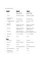
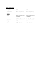
SERVICE MANUAL
ULD - 15 / 18
edited by Michael Sands from word document supplied by Velodyne 20140123
System Specifications:
Amplifier:
ULD - 18
Type:
Power:
Input Sensitivity/
Impedance:
Frequency Response:
-3dB
Crossover:
High Pass
Low Pass
Protection:
ULD - 15
High efficiency
Discreet Class B
High Efficiency
Discreet Class B
400 Watts cont. RMS
400 Watts cont. RMS
300mv/20k ohms
300mv/20k ohms
18 - 85Hz, +/-3dB
13 Hz
18 - 85 Hz, +/-3dB
14 Hz
Modular Active 85Hz;
12dB Per Octave
Modular Active 85Hz;
12dB Per Octave
Modular Active 85Hz;
12dB Per Octave
Modular Active 85Hz;
12dB Per Octave
Open / Short Circuit
Open / Short Circuit
Excessive Signal, Low Line.
Excessive Signal, Low Line.
Dimensions:
17 x 12 x 4 (LWH)
17 x 12 x 4 (LWH)
Weight:
15 lbs.
15 lbs.
Linear Travel:
3/4 inches
5/8 inches
Voice Coil:
Edgewound Copper 3” Edgewound Copper 3”
Magnet:
216 Oz.
216 Oz.
Cone:
Resin Impregnated Fiber.
Resin Impregnated Fiber.
Driver Resonant Freq. :
< 4 Hz
< 4 Hz
Max Distortion:
(20 Hz & 104 dB)
< .5 %
< .5 %
Driver:
Servo Feedback Loop:
Loop Gain:
30dB
30dB
Accelerometer:
Piezo w/ integral amp.
Piezo w/integral amp.
Finish:
Black Wood Grain, Oak
and Walnut.
Black Wood Grain, Oak
and Walnut.
Dimensions:
31” x 23 1/2” x 21 1/ 2” 22 1/2” x 17” x 18 1/2”
Weight:
105 lbs.
90 lbs.
Volume:
9976 cubic inches.
4313 cubic inches.
Cabinet:
System Operation
The ULD - 15 / 18 Subwoofer system is a 2 piece downward firing subwoofer system consisting
of a separate servo controller / amplifier and a sealed cabinet which houses the 15 or 18 inch
driver and servo interface. The system is designed to operate with line level inputs, which can be
made to either a pre-amp, tape loop, line level crossover, or signal line level outputs. The
connections to and from the ULD servo controller can be made with any shielded phono cables,
with connection back to the main system being required in order to provide the output of the
internal high pass filter to the main system amplifier. The connection to the Velodyne driver can
be made with the same quality cable that would normally be used for any standard speaker hookup. The servo connection between the Velodyne amp and driver is made with a single RCA
cable. The Velodyne will reproduce those frequencies below the set low-pass crossover point and
will pass all frequencies above the set high-pass point out to the satellite speakers. The factory
set default frequency for the crossover high and low-pass is 85 Hz. The level control on the ULD
servo controller is a sensitivity adjustment used to set a relative level between the satellite
speakers and the Velodyne unit, once this level is properly set very little if any adjustment
should be required. The only notable exception to this rule occurs is when the servo controller is
connected to the system via the tape monitor loop, in which case the level control on the servocontroller will need to be adjusted every time the system volume is adjusted; this occurs because
the tape loop level is fixed and unaffected by changes in the overall system level.
Component Removal
Amp: Access to the amplifier assembly is gained by removing the ten screws which secure the
top cover of the unit. The main PC board of the amplifier is secured to the chassis by three
screws which run through the back of the unit, along with three plastic standoffs that protrude
through the the bottom of the chassis. Prior to removing the mother board the two molex
connectors processor located at the rear of the board must be removed along with the red & black
speaker leads as well as the transformer leads. The volume pot is removed by pulling the knob
off and then removing the captive nut and star washer which secure the pot to the chassis.
Service technicians should pay special attention to the location of all the transformer leads and
mark them since some mother boards are not marked or color coded.
Driver: Access to the driver and sender board can be gained by removing the eight screws
around the perimeter of the driver and the four screws around the terminal plate. In some
instances it may be necessary to pry the driver out of the cabinet with a screwdriver; the driver
and the terminal plate will then come out as a unit with the wires connected between them. Do
not under any circumstances cut these wires in order to remove these components.
Board identification
Sender board: The sender board is the board that resides within the subwoofer cabinet at the
point where the servo and speaker wires from the servo controller connect. This board is
responsible for amplifying the accelerometer signal from the driver and transmitting it to the
amplifier via the servo cable.
Output boards: The output boards are the boards that are attached to the heat sink assemblies
at either side of the amplifier assembly. The output boards provide final signal amplification of
the output signal prior to the driver. The aluminum bracket that the power transistors are bolted
to is isolated from chassis ground via a layer of thermal compound and a thin sheet of nonconductive paper. The red and black wires attached to the boards designate the polarity of the
output signal, red is positive (+65Vdc), black is negative (-65Vdc).
Preamp board: The preamp board is located on the left side of the mother board and can be
identified by the four transistors that are at the top rear edge of the board. Each of the transistors
has a large machine screw that runs through it for heat sinking. The preamp board is responsible
for setting the bias current to the output transistors, splitting the signal into its positive and
negative components, and sending the signal to the output boards.
Crossover board: The crossover board is the board located on the rear of the amp mother
board, parallel to the front and rear panel. The crossover board is the one that has the volume pot
and crossover module attached to it. It is responsible for setting the low and high pass crossover
points as well as the level of the incoming signal. The crossover board is the only circuit that the
signal out of the Velodyne controller passes through, service technicians can safely assume that
any noise detected at the satellite speakers can be eliminated through the repair of this board.
Refer to the inserts on the modification of the ULD crossover for information on selecting the
proper resistor values to alter the high and low pass crossover frequencies.
Gain compressor board: The gain compressor board is located on the extreme left edge of the
mother board. It is easily identified by the two adjustable pots located at the top of the board.
These two pot VR1 & VR2 are responsible for setting the maximum gain at 20Hz and 100Hz
respectively.
Loop board: The loop board is the next board in from the gain compressor board. It is
responsible for amplifying the signal and summing the feedback signal with the incoming signal.
Comparitor board: The comparator board is the second board in from the gain compressor
board. It can be identified by the transistor that is located at the top rear edge of the board close
to the crossover board. The comparator board is responsible for changing the current signal from
the accelerometer into an AC voltage signal and for turning on the amplifier. This board monitors
several signals and when all these signals are present it then energizes the bias circuit for the
output transistors on the preamp board.
Schematic Overview
Signals enter the ULD amplifier through the RCA input jacks located on the rear panel. The
signal goes directly to the Crossover Board where it is crossed over and the higher frequencies
are routed back out to the satellite speakers via the power amp.
From the crossover board the low frequency signal is routed to the Loop Board where it is
amplified by the first op amp of IC U7 (LM348).
The output of that circuit is routed to the Gain Compressor Board where it is evaluated and sets
IC U3 (NE572, a programmable analog compander) which acts as a variable feedback resistor
for the following gain stage on the Loop Board.
The third op amp on the Loop Board is a filter and the fourth op amp is the summing point for
the music signal and the accelerometer signal. The resulting signal when summed is what
provides the error correction necessary to make the driver accurately reproduce the input signal.
The accelerometer signal originates at the Piezo Element which is mounted on the driver voice
coil. The signal starts as an AC signal and is routed from the driver out to the Sender Board via
the 4 conductor black ribbon cable.
Once at the Sender Board IC U1(NE5534) and TR2 (2N3904) combine to change the signal from
an analog AC signal into modulated current, which is then transmitted through the RCA cable up
to the amplifier.
Once in the amplifier this signal is routed to the Comparator Board where it passes through IC
U8 (NE5534) and is converted back to an AC signal. It is at that point that the signal is routed to
the loop board via pin J7-1 and onto IC U7 pin 9 (inverting input of the fourth op amp).
The summed signal travels out of the Loop Board and on to the Preamp Board via a twisted pair
wire set. Once the signal arrives at the Preamp Board it gets split into its positive and negative
components and sent out to the Output Boards, where it gets amplified and passed out to the
driver via the banana plugs on the rear.
One additional function of the Comparator Board is to provide the turn on circuit for the
amplifier. It accomplishes this by controlling the transistor bias circuit located on the Preamp
Board. By monitoring various voltages with IC’s U5 & U6 (Lm339’s) the Comparator Board is
capable of preventing the amp from turning on when any of the required inputs is missing.
System Calibration
Proper calibration of the amp and driver is essential to ensure correct operation of the system.
Calibration of the system involves setting the accelerometer feedback level to the amplifier and
the setting of the gain compression circuits in the amp. Driver or accelerometer calibration is
performed by adjusting the pot located on the sender board. The pot is accessed through the
large screw in the metal terminal plate on the underside of the subwoofer cabinet, just to the
right of the servo RCA jack. To calibrate the unit, set the signal generator output to 100 HZ at a
level of .8 Vrms. Turn the two pots on the Gain Compressor Board VR1 & VR2 fully
clockwise. Turn the amplifier Volume Pot unit you have 20V P-P output at the banana plugs on
the rear of the amplifier. Measure the feedback signal from the accelerometer at Pin J6 - 5 on the
Comparator Board, verify .40 V peak to peak. If this signal measures less than .40V p-p readjust the sender board pot until the proper signal level is achieved. Repeat this operation until
the proper levels are achieved throughout. The driver must be sealed in the cabinet during this
entire process.
System Test Points
All test point values are measured using a .8 Vrms, 100 Hz input signal into either of the Line
level input jacks. The speaker must be connected to the amp and installed into a sealed cabinet,
calibrated and both Gain Compressor Board pots turned completely clockwise. Any distortion
heard is actually the Gain Compression circuit activating to prevent the driver from bottoming
out.
Test Point
Location
Value
TP1
TP2
TP3
TP4
TP5
TP6
TP7
TP8
TP9
TP10
TP11
TP12
TP13
TP14
TP15
TP16
TP17
TP18
J6 - 1 Comp Pcb.
J6 - 6 Comp Pcb.
J6 - 4 Comp Pcb.
J5 - 2 Comp Pcb.
J5 - 1 Comp Pcb.
IC U5 Pin 14, Comp Pcb.
IC U8 Pin 6, Comp Pcb.
J6 - 5 Comp Pcb.
IC U7 Pin 1, Loop Pcb.
IC U7 Pin 7, Loop Pcb.
IC U7 Pin 8, Loop Pcb.
Left Heatsink
Right Heatsink
Pin 1, Red Output Brd.
Pin 2, Red Output Brd.
Pin 1, Blk. Output Brd.
Pin 2, Blk. Output Brd.
Red Spkr. Output
62 Vdc
12 Vdc
29 Vdc
.1 Vdc
0 Vdc
12 Vdc
0 Vdc
1V p-p @ 17.5 Vdc
1V p-p max
4.4 V p-p max
4 V p-p max
.3 V p-p max
-30 Vdc
30 Vdc
30 Vdc
65 Vdc
-30 Vdc
-65 Vdc
50 V p-p @ 20Hz*
60 V p-p @ 100Hz*
* Levels at TP18 are adjustable via Gain Compressor Board pots VR1 and VR2 respectively.
Troubleshooting
Common Problems
Symptom
Cure
No power
Make sure RCA cable is good.
Check all five fuses to make sure they
are all good.
Check that transformer is not open.
Make sure there is actually no power
and not just a bad or unplugged LED
by checking both the voltage and the
LED connection inside the amp.
Symptom
Cure
Driver makes a big
slow oscillation.
Check cabinet for air leaks around the
driver and sender board. Tighten the
hardware around both if an air leak is
detected. If leaks persists reseal with new
gasket material.
Unit pops every 3-5
seconds repeatedly.
Check output transistors on both output
stages for shorted devices. Usually means
there’s DC at the output binding posts.
Always attempt to isolate problems to the
defective piece by using the suspect piece
with a known good unit.
Installation of components
Driver: Make sure the gasket material surrounding the driver opening in not torn and in
otherwise good shape prior to the reinstallation of the driver. If that is not the case replace the
gasket with new gasket material, and or weather stripping for the ULD - 18. Insert the sender
board into the cabinet so that it can be reached through the sender board hole. Reach in and
grab the sender board and screw it into place, using the four machine screws. When installing
the sender board make sure the red and black terminals match the indicators on the warning lable
that is afixed to the cabinet. Place the driver into the driver hole making sure to rotate it so as to
eliminate any excessive slack in the interconnect wires running between the driver and sender
board; now re-secure the driver using the eight machine screws. If the gasket material for a ULD
- 18 has been replaced it may be necessary to punch holes into the weather stripping in order to
install the screws without interference. Tighten down the screws in a clockwise manner working
your way around the driver until all the screws are secured.
Amplifier Mother Board: Place mother board into the chassis assembly so that the RCA jacks
and fuse holders fit into their respective holes in the rear panel. Screw the amp board into the
chassis with the three machine screws, and align the teflon standoffs on the mother board with
the holes on the chassis bottom. Reconnect all transformer wires to the appropriate standoffs
following the color markings on the board and reconnect the red and black speaker connectors
from the rear panel binding posts; making sure all the connections are tight and secure.
Reconnect the Molex connectors from the positive and negative output boards to the main board,
all terminals on the mother board are marked to identify the proper color and orientation. Be
sure all connections are pushed completely onto the board. Secure the amplifier lid with the ten
screws.
Final Checks
Turn on the unit and feed in a 20Hz signal. Check around the perimeter of the driver for air leaks
and ticking. When properly calibrated the unit should turn itself off when the volume of the
amplifier is turned up beyond the 3 O’clock position, after shutoff return amplifier volume
setting to minimum. Change the input signal frequency to 100 Hz and turn the amplifier volume
level to full. When properly calibrated the unit should play without clipping or distortion. If the
unit fails to do so the unit calibration and gain compressor setting need to be checked and
readjusted.
Modification of High and Low Pass Frequencies in the ULD - 15/18
This information is applicable to all ULD - 15/18 controllers with serial numbers prior to
51161007; this includes all units with four digit serial numbers that utilize a single RCA servo
connector.
The unit comes equipped with default crossover frequencies of 85 Hz. The High and Low pass
frequencies can be altered from the default values by removing a resistor pack from the 14 pin
socket on the Crossover Board, and replacing the resistor pack with an IC header which has the
resistors that correspond to the desired crossover frequencies soldered to it. Please refer to the
following illustration and text to determine the correct resistor values.
Low Pass
High Pass
High Pass
High Pass
High Pass
1
2
3
4
5
6
7
o - - o 14
o
o 13
o - L - o 12
o - H - o 11
o - H - o 10
o-H-o 9
o-H-o 8
Shorting Bar
Open
75K Ohm (Default)
47K Ohm (Default)
47K Ohm (Default)
47K Ohm (Default)
47K Ohm (Default)
The above illustration represents the IC header as seen from above. The shorting bar at the top
of the header is for inverting phase, if a 180 degree phase inversion is desired the shorting bar
should be placed between pins 2 and 13. Do not short both pins 1 and 14 and pins 2 and 13 at
the same time. Such action will result in damage to the crossover board along with lack of
output from the subwoofer. The shorting bar should remain unchanged regardless of the
crossover frequency.
Determining the resistor values for the remaining five positions on the header can be done by
using the following formulas. The Low Pass frequency can be altered by changing the resistor
value across pins 3 and 12, the formula for the Low Pass is as follows: R = 6375 / F. In the
formula R is the value of the resistor measured in K Ohms, and F is the desired crossover
frequency. The High Pass frequency can be altered by changing the remaining four resistors on
the IC header, the formula for determining the High Pass is as follows: R = 4000 / F. Once again
in the formula R is the value of the resistor measured in K Ohms, and F is the desired crossover
frequency.
As an example if someone desired a crossover of 40 Hz installed in their subwoofer it would be
obtained by by using a 160K Ohm resistor for the Low Pass , “L” position along with four 100 K
Ohm resistors in the remaining High Pass, “H” positions.
All four resistors must be changed in order to adjust the High Pass; only the one resistor needs to
be changed in order to alter the Low Pass frequency. The High and Low Pass are user definable
and can be set to leave either a gap between them or an overlap if room characteristics make that
desirable.
Modification of High and Low Pass Frequencies in the ULD - 15/18
This information is applicable to all ULD - 15/18 Series II controllers with serial numbers that
are later than 51161007.
The unit comes equipped with default crossover frequencies of 85 Hz. The High and Low pass
frequencies can be altered from the default values by removing a resistor pack from the 14 pin
socket on the Crossover Board, and replacing the resistor pack with an IC header which has the
resistors that correspond to the desired crossover frequencies soldered to it.
Please refer to the following illustration and text to determine the correct resistor values.
Low Pass
High Pass
High Pass
High Pass
High Pass
1
2
3
4
5
6
7
o
o 14
o
o 13
o -L -o 12
o -H- o 11
o -H- o 10
o -H- o 9
o -H- o 8
47K Ohm
Open
47K Ohm (Default)
47K Ohm (Default)
47K Ohm (Default)
47K Ohm (Default)
47K Ohm (Default)
The above illustration represents the IC header as seen from above. The 47K Ohm resistor at the
top of the header replaces resistor R - 72 which was omitted from all later revision crossover
boards. As with the earlier version of the crossover module the top two rows of pins are for
inverting phase. Do not short both pins 1 and 14 and pins 2 and 13 at the same time. Such action
will result in damage to the crossover board along with lack of output from the subwoofer. If a
180 degree phase invertion is desired the 47K Ohm resistor should be placed between pins 2 and
13. The value of resistance should remain unchanged regardless of the crossover frequency.
Determining the resistor value for the remaining five positions can be calculated by using the
following formula: R = 4000 / F. In the formula R is the value of the resistor measured in K
Ohm, and F is the desired crossover frequency. As an example if someone desired a crossover of
40 Hz installed in their subwoofer it would be obtained by using 100K Ohm resistors in all five
positions (Pins 3-12, 4-11, 5-10, 6-9, 7-8).
All four resistors must be changed in order to adjust the High Pass; only the one resistor needs to
be changed in order to alter the Low Pass frequency. The High and Low Pass are user definable
and can be set to leave either a gap between them or an overlap if room characteristics make that
desirable.
Eliminating the Low Pass Filter
When one of your customers wants to use a Velodyne ULD -15/18 with an external crossover,
the Low - Pass should be raised to value a minimum of 1 octave above the Low Pass frequency
employed by the external unit. As an example if someone desired to use a subwoofer output with
a 100 Hz Low Pass the Low pass within the Velodyne should be change to 200 Hz by installing a
20K Ohm resistor.
Modification of the ULD - 18 for THX operation.
The model ULD -18 Subwoofer is available in a THX certified version for use with other THX
certified components. The THX certified version of the ULD - 18 differs from the Non - THX
version in two ways. The THX version has no volume pot on the amplifier / controller but is
designed to operate at a fixed output level supplied via the subwoofer output port of a THX
certified preamp. In addition the THX amplifier is supplied with a modified crossover module
(P/N-84-0003)which plugs into the 14 pin socket normally reserved for the default 85 Hz
crossover chip. Any ULD - 18 Series II controller can thus be modified to THX specification by
the addition of the THX module and omission of the volume pot or vice versa. The function of
the THX crossover module is to raise the Low Pass frequency to 200 Hz while maintaining the
default 85 Hz High Pass level, while at the same time boosting the signal level at 35 Hz.