1
Remeha Gas 110 Eco
EN
Gas fired condensing boiler
Gas 110 Eco 115 / 65
Rem eha
Installation, User and
Service Manual
300014883-001-K
Declaration of conformity 1
C002718-B
The appliance complies with the standard model described in
declaration of compliance 1. It is manufactured and distributed
pursuant to the requirements of european directives. The original of
the declaration of compliance is available from the manufacturer.
2
Gas 110 Eco 115 / 65
25/01/2011 - 300014883-001-K
Contents
1
Used symbols . . . . . . . . . . . . . . . . . . . . . . . . . . . . . . . . . . . . . . . . . . . . . . . . . . . . . . . . . . . . . . . . . . . . . . . . . . .5
2
Important recommendations . . . . . . . . . . . . . . . . . . . . . . . . . . . . . . . . . . . . . . . . . . . . . . . . . . . . . . . . . . . . . . .5
3
Description. . . . . . . . . . . . . . . . . . . . . . . . . . . . . . . . . . . . . . . . . . . . . . . . . . . . . . . . . . . . . . . . . . . . . . . . . . . . . .6
3.1
3.2
General. . . . . . . . . . . . . . . . . . . . . . . . . . . . . . . . . . . . . . . . . . . . . . . . . . . . . . . . . . . . . . . . . . . . . . . . . . . . . . . . . . . . . . . . . . . . . . . .6
Homologations . . . . . . . . . . . . . . . . . . . . . . . . . . . . . . . . . . . . . . . . . . . . . . . . . . . . . . . . . . . . . . . . . . . . . . . . . . . . . . . . . . . . . . . . . .6
3.2.1
General instructions . . . . . . . . . . . . . . . . . . . . . . . . . . . . . . . . . . . . . . . . . . . . . . . . . . . . . . . . . . . . . . . . . . . . . . . . . . . . . . . .6
3.2.2
Gas categories . . . . . . . . . . . . . . . . . . . . . . . . . . . . . . . . . . . . . . . . . . . . . . . . . . . . . . . . . . . . . . . . . . . . . . . . . . . . . . . . . . . .6
3.3 Main parts. . . . . . . . . . . . . . . . . . . . . . . . . . . . . . . . . . . . . . . . . . . . . . . . . . . . . . . . . . . . . . . . . . . . . . . . . . . . . . . . . . . . . . . . . . . . . .7
3.4 Technical characteristics . . . . . . . . . . . . . . . . . . . . . . . . . . . . . . . . . . . . . . . . . . . . . . . . . . . . . . . . . . . . . . . . . . . . . . . . . . . . . . . . . .9
3.4.1
Boiler . . . . . . . . . . . . . . . . . . . . . . . . . . . . . . . . . . . . . . . . . . . . . . . . . . . . . . . . . . . . . . . . . . . . . . . . . . . . . . . . . . . . . . . . . . .9
3.4.2
Control panel . . . . . . . . . . . . . . . . . . . . . . . . . . . . . . . . . . . . . . . . . . . . . . . . . . . . . . . . . . . . . . . . . . . . . . . . . . . . . . . . . . . . .9
3.5 Technical data . . . . . . . . . . . . . . . . . . . . . . . . . . . . . . . . . . . . . . . . . . . . . . . . . . . . . . . . . . . . . . . . . . . . . . . . . . . . . . . . . . . . . . . . .10
3.6 Main dimensions. . . . . . . . . . . . . . . . . . . . . . . . . . . . . . . . . . . . . . . . . . . . . . . . . . . . . . . . . . . . . . . . . . . . . . . . . . . . . . . . . . . . . . . .11
3.6.1
Boiler self-standing. . . . . . . . . . . . . . . . . . . . . . . . . . . . . . . . . . . . . . . . . . . . . . . . . . . . . . . . . . . . . . . . . . . . . . . . . . . . . . . .11
3.6.2
Boiler installed . . . . . . . . . . . . . . . . . . . . . . . . . . . . . . . . . . . . . . . . . . . . . . . . . . . . . . . . . . . . . . . . . . . . . . . . . . . . . . . . . . .12
3.7 Hydraulic specifications . . . . . . . . . . . . . . . . . . . . . . . . . . . . . . . . . . . . . . . . . . . . . . . . . . . . . . . . . . . . . . . . . . . . . . . . . . . . . . . . . .13
4
Control and safety equipment . . . . . . . . . . . . . . . . . . . . . . . . . . . . . . . . . . . . . . . . . . . . . . . . . . . . . . . . . . . . .14
4.1
Control panel . . . . . . . . . . . . . . . . . . . . . . . . . . . . . . . . . . . . . . . . . . . . . . . . . . . . . . . . . . . . . . . . . . . . . . . . . . . . . . . . . . . . . . . . . .14
4.1.1
General . . . . . . . . . . . . . . . . . . . . . . . . . . . . . . . . . . . . . . . . . . . . . . . . . . . . . . . . . . . . . . . . . . . . . . . . . . . . . . . . . . . . . . . .14
4.1.2
Layout of the control panel. . . . . . . . . . . . . . . . . . . . . . . . . . . . . . . . . . . . . . . . . . . . . . . . . . . . . . . . . . . . . . . . . . . . . . . . . .14
4.1.3
Combined key functions (in operating mode only) . . . . . . . . . . . . . . . . . . . . . . . . . . . . . . . . . . . . . . . . . . . . . . . . . . . . . . . .15
4.1.4
Display of values with more than two digits . . . . . . . . . . . . . . . . . . . . . . . . . . . . . . . . . . . . . . . . . . . . . . . . . . . . . . . . . . . . .15
4.2 Flow diagram control system . . . . . . . . . . . . . . . . . . . . . . . . . . . . . . . . . . . . . . . . . . . . . . . . . . . . . . . . . . . . . . . . . . . . . . . . . . . . . .16
4.3 Operating mode (N>>) . . . . . . . . . . . . . . . . . . . . . . . . . . . . . . . . . . . . . . . . . . . . . . . . . . . . . . . . . . . . . . . . . . . . . . . . . . . . . . .17
4.4 Shut-off mode (B<<) . . . . . . . . . . . . . . . . . . . . . . . . . . . . . . . . . . . . . . . . . . . . . . . . . . . . . . . . . . . . . . . . . . . . . . . . . . . . . . . . .18
4.5 Setting mode user level (<>>). . . . . . . . . . . . . . . . . . . . . . . . . . . . . . . . . . . . . . . . . . . . . . . . . . . . . . . . . . . . . . . . . . . . . . . . . .18
4.5.1
Flow temperature set point (). . . . . . . . . . . . . . . . . . . . . . . . . . . . . . . . . . . . . . . . . . . . . . . . . . . . . . . . . . . . . . . . . . . . . .19
4.5.2
Pump run on time HTG ()) . . . . . . . . . . . . . . . . . . . . . . . . . . . . . . . . . . . . . . . . . . . . . . . . . . . . . . . . . . . . . . . . . . . . . . . .19
4.5.3
DHW temperature set-point ( ) . . . . . . . . . . . . . . . . . . . . . . . . . . . . . . . . . . . . . . . . . . . . . . . . . . . . . . . . . . . . . . . . . . . . .20
4.5.4
Boiler control setting (*). . . . . . . . . . . . . . . . . . . . . . . . . . . . . . . . . . . . . . . . . . . . . . . . . . . . . . . . . . . . . . . . . . . . . . . . . . .20
4.6 Setting mode service level (<) . . . . . . . . . . . . . . . . . . . . . . . . . . . . . . . . . . . . . . . . . . . . . . . . . . . . . . . . . . . . . . . . . . . . . . .21
4.6.1
Flow temperature set point during forced part load () . . . . . . . . . . . . . . . . . . . . . . . . . . . . . . . . . . . . . . . . . . . . . . . . . . .22
4.6.2
High limit thermostat () . . . . . . . . . . . . . . . . . . . . . . . . . . . . . . . . . . . . . . . . . . . . . . . . . . . . . . . . . . . . . . . . . . . . . . . . . .22
4.6.3
Fan speed at full load HTG (?) . . . . . . . . . . . . . . . . . . . . . . . . . . . . . . . . . . . . . . . . . . . . . . . . . . . . . . . . . . . . . . . . . . . . .22
4.6.4
Fan speed at part load (HTG and DHW - ) . . . . . . . . . . . . . . . . . . . . . . . . . . . . . . . . . . . . . . . . . . . . . . . . . . . . . . . . . . .22
4.6.5
Starting point modulation () . . . . . . . . . . . . . . . . . . . . . . . . . . . . . . . . . . . . . . . . . . . . . . . . . . . . . . . . . . . . . . . . . . . . . . .22
4.6.6
Interface selection () . . . . . . . . . . . . . . . . . . . . . . . . . . . . . . . . . . . . . . . . . . . . . . . . . . . . . . . . . . . . . . . . . . . . . . . . . . . .22
4.6.7
DHW cut-in temperature (+) . . . . . . . . . . . . . . . . . . . . . . . . . . . . . . . . . . . . . . . . . . . . . . . . . . . . . . . . . . . . . . . . . . . . . . .23
4.6.8
Fan Speed at DHW full load (0). . . . . . . . . . . . . . . . . . . . . . . . . . . . . . . . . . . . . . . . . . . . . . . . . . . . . . . . . . . . . . . . . . . . .23
4.6.9
Forced part load time after start (HTG only - /). . . . . . . . . . . . . . . . . . . . . . . . . . . . . . . . . . . . . . . . . . . . . . . . . . . . . . . . .23
4.6.10 DHW control stop set point (2) . . . . . . . . . . . . . . . . . . . . . . . . . . . . . . . . . . . . . . . . . . . . . . . . . . . . . . . . . . . . . . . . . . . . .23
4.6.11 DHW control option (3) . . . . . . . . . . . . . . . . . . . . . . . . . . . . . . . . . . . . . . . . . . . . . . . . . . . . . . . . . . . . . . . . . . . . . . . . . . .23
4.6.12 HTG cut in temp (5) . . . . . . . . . . . . . . . . . . . . . . . . . . . . . . . . . . . . . . . . . . . . . . . . . . . . . . . . . . . . . . . . . . . . . . . . . . . . . .23
4.6.13 Boiler type (7) . . . . . . . . . . . . . . . . . . . . . . . . . . . . . . . . . . . . . . . . . . . . . . . . . . . . . . . . . . . . . . . . . . . . . . . . . . . . . . . . . .23
4.6.14 Maximum delay time (;) . . . . . . . . . . . . . . . . . . . . . . . . . . . . . . . . . . . . . . . . . . . . . . . . . . . . . . . . . . . . . . . . . . . . . . . . . .24
4.6.15 Start and end point analog signal ( and =) . . . . . . . . . . . . . . . . . . . . . . . . . . . . . . . . . . . . . . . . . . . . . . . . . . . . . . . . . .24
4.7 Read-out mode (<) . . . . . . . . . . . . . . . . . . . . . . . . . . . . . . . . . . . . . . . . . . . . . . . . . . . . . . . . . . . . . . . . . . . . . . . . . . . . . . . .25
4.8 Fan speed mode (') . . . . . . . . . . . . . . . . . . . . . . . . . . . . . . . . . . . . . . . . . . . . . . . . . . . . . . . . . . . . . . . . . . . . . . . . . . . . . . .25
4.9 Failure mode (N) . . . . . . . . . . . . . . . . . . . . . . . . . . . . . . . . . . . . . . . . . . . . . . . . . . . . . . . . . . . . . . . . . . . . . . . . . . . . . . . . . .25
5
Installation . . . . . . . . . . . . . . . . . . . . . . . . . . . . . . . . . . . . . . . . . . . . . . . . . . . . . . . . . . . . . . . . . . . . . . . . . . . . .26
5.1
Statutory terms and conditions of installation and maintenance. . . . . . . . . . . . . . . . . . . . . . . . . . . . . . . . . . . . . . . . . . . . . . . . . . . .26
25/01/2011 - 300014883-001-K
Gas 110 Eco 115 / 65
3
5.2
5.3
5.4
5.5
5.6
5.7
5.8
6
Important comments on the treatment of the heating circuit. . . . . . . . . . . . . . . . . . . . . . . . . . . . . . . . . . . . . . . . . . . . . . . . . . . . . . .27
Water discharge connection . . . . . . . . . . . . . . . . . . . . . . . . . . . . . . . . . . . . . . . . . . . . . . . . . . . . . . . . . . . . . . . . . . . . . . . . . . . . . . .29
Room sealed installations. . . . . . . . . . . . . . . . . . . . . . . . . . . . . . . . . . . . . . . . . . . . . . . . . . . . . . . . . . . . . . . . . . . . . . . . . . . . . . . . .29
Checking the gas inlet (Boiler only) . . . . . . . . . . . . . . . . . . . . . . . . . . . . . . . . . . . . . . . . . . . . . . . . . . . . . . . . . . . . . . . . . . . . . . . . .29
Reversal of the direction the control panel access door opens . . . . . . . . . . . . . . . . . . . . . . . . . . . . . . . . . . . . . . . . . . . . . . . . . . . .30
Levelling . . . . . . . . . . . . . . . . . . . . . . . . . . . . . . . . . . . . . . . . . . . . . . . . . . . . . . . . . . . . . . . . . . . . . . . . . . . . . . . . . . . . . . . . . . . . . .32
Handling the boiler . . . . . . . . . . . . . . . . . . . . . . . . . . . . . . . . . . . . . . . . . . . . . . . . . . . . . . . . . . . . . . . . . . . . . . . . . . . . . . . . . . . . . .32
Connecting the flue . . . . . . . . . . . . . . . . . . . . . . . . . . . . . . . . . . . . . . . . . . . . . . . . . . . . . . . . . . . . . . . . . . . . . .33
6.1
Flue pipe connections. . . . . . . . . . . . . . . . . . . . . . . . . . . . . . . . . . . . . . . . . . . . . . . . . . . . . . . . . . . . . . . . . . . . . . . . . . . . . . . . . . . .33
6.1.1
Classification . . . . . . . . . . . . . . . . . . . . . . . . . . . . . . . . . . . . . . . . . . . . . . . . . . . . . . . . . . . . . . . . . . . . . . . . . . . . . . . . . . . .34
6.1.2
Lengths of the air/flue gas pipes . . . . . . . . . . . . . . . . . . . . . . . . . . . . . . . . . . . . . . . . . . . . . . . . . . . . . . . . . . . . . . . . . . . . .35
6.2 Electrical connection. . . . . . . . . . . . . . . . . . . . . . . . . . . . . . . . . . . . . . . . . . . . . . . . . . . . . . . . . . . . . . . . . . . . . . . . . . . . . . . . . . . . .36
7
Start-up. . . . . . . . . . . . . . . . . . . . . . . . . . . . . . . . . . . . . . . . . . . . . . . . . . . . . . . . . . . . . . . . . . . . . . . . . . . . . . . .38
7.1
7.2
Filling the system . . . . . . . . . . . . . . . . . . . . . . . . . . . . . . . . . . . . . . . . . . . . . . . . . . . . . . . . . . . . . . . . . . . . . . . . . . . . . . . . . . . . . . .38
Check points before commissioning. . . . . . . . . . . . . . . . . . . . . . . . . . . . . . . . . . . . . . . . . . . . . . . . . . . . . . . . . . . . . . . . . . . . . . . . .38
7.2.1
Checking the gas supply pressure . . . . . . . . . . . . . . . . . . . . . . . . . . . . . . . . . . . . . . . . . . . . . . . . . . . . . . . . . . . . . . . . . . . .38
7.3 Putting the appliance into operation . . . . . . . . . . . . . . . . . . . . . . . . . . . . . . . . . . . . . . . . . . . . . . . . . . . . . . . . . . . . . . . . . . . . . . . . .39
7.3.1
Gas 110 Eco 65 . . . . . . . . . . . . . . . . . . . . . . . . . . . . . . . . . . . . . . . . . . . . . . . . . . . . . . . . . . . . . . . . . . . . . . . . . . . . . . . . . .40
7.3.2
Gas 110 Eco 115 . . . . . . . . . . . . . . . . . . . . . . . . . . . . . . . . . . . . . . . . . . . . . . . . . . . . . . . . . . . . . . . . . . . . . . . . . . . . . . . . .41
7.4 Programming boiler control . . . . . . . . . . . . . . . . . . . . . . . . . . . . . . . . . . . . . . . . . . . . . . . . . . . . . . . . . . . . . . . . . . . . . . . . . . . . . . .42
7.5 Instruct the user of the boiler . . . . . . . . . . . . . . . . . . . . . . . . . . . . . . . . . . . . . . . . . . . . . . . . . . . . . . . . . . . . . . . . . . . . . . . . . . . . . .42
7.6 Shut-down . . . . . . . . . . . . . . . . . . . . . . . . . . . . . . . . . . . . . . . . . . . . . . . . . . . . . . . . . . . . . . . . . . . . . . . . . . . . . . . . . . . . . . . . . . . .42
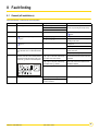
8
Fault finding . . . . . . . . . . . . . . . . . . . . . . . . . . . . . . . . . . . . . . . . . . . . . . . . . . . . . . . . . . . . . . . . . . . . . . . . . . . .43
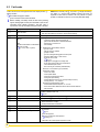
8.1
8.2
9
General (all installations) . . . . . . . . . . . . . . . . . . . . . . . . . . . . . . . . . . . . . . . . . . . . . . . . . . . . . . . . . . . . . . . . . . . . . . . . . . . . . . . . .43
Fault codes . . . . . . . . . . . . . . . . . . . . . . . . . . . . . . . . . . . . . . . . . . . . . . . . . . . . . . . . . . . . . . . . . . . . . . . . . . . . . . . . . . . . . . . . . . . .44
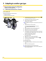
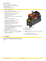
Adapting to another gas type. . . . . . . . . . . . . . . . . . . . . . . . . . . . . . . . . . . . . . . . . . . . . . . . . . . . . . . . . . . . . .46
9.1
9.2
Switching from Natural Gas to Propane . . . . . . . . . . . . . . . . . . . . . . . . . . . . . . . . . . . . . . . . . . . . . . . . . . . . . . . . . . . . . . . . . . . . . .46
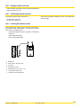
Gas type . . . . . . . . . . . . . . . . . . . . . . . . . . . . . . . . . . . . . . . . . . . . . . . . . . . . . . . . . . . . . . . . . . . . . . . . . . . . . . . . . . . . . . . . . . . . . .47
10 Maintenance. . . . . . . . . . . . . . . . . . . . . . . . . . . . . . . . . . . . . . . . . . . . . . . . . . . . . . . . . . . . . . . . . . . . . . . . . . . .48
10.1 General. . . . . . . . . . . . . . . . . . . . . . . . . . . . . . . . . . . . . . . . . . . . . . . . . . . . . . . . . . . . . . . . . . . . . . . . . . . . . . . . . . . . . . . . . . . . . . .48
10.2 Inspection . . . . . . . . . . . . . . . . . . . . . . . . . . . . . . . . . . . . . . . . . . . . . . . . . . . . . . . . . . . . . . . . . . . . . . . . . . . . . . . . . . . . . . . . . . . . .48
10.2.1 Checking the combustion in the boiler . . . . . . . . . . . . . . . . . . . . . . . . . . . . . . . . . . . . . . . . . . . . . . . . . . . . . . . . . . . . . . . . .48
10.2.2 Setting the ignition electrode . . . . . . . . . . . . . . . . . . . . . . . . . . . . . . . . . . . . . . . . . . . . . . . . . . . . . . . . . . . . . . . . . . . . . . . .49
10.2.3 Checking the hydraulic pressure . . . . . . . . . . . . . . . . . . . . . . . . . . . . . . . . . . . . . . . . . . . . . . . . . . . . . . . . . . . . . . . . . . . . .49
10.2.4 Checking the ionization current . . . . . . . . . . . . . . . . . . . . . . . . . . . . . . . . . . . . . . . . . . . . . . . . . . . . . . . . . . . . . . . . . . . . . .49
10.3 Cleaning and maintenance. . . . . . . . . . . . . . . . . . . . . . . . . . . . . . . . . . . . . . . . . . . . . . . . . . . . . . . . . . . . . . . . . . . . . . . . . . . . . . . .50
10.4 Maintenance of the air/flue gas drain connection flues . . . . . . . . . . . . . . . . . . . . . . . . . . . . . . . . . . . . . . . . . . . . . . . . . . . . . . . . . .53
10.5 Temperature sensor . . . . . . . . . . . . . . . . . . . . . . . . . . . . . . . . . . . . . . . . . . . . . . . . . . . . . . . . . . . . . . . . . . . . . . . . . . . . . . . . . . . . .53
11 Schematic diagrams . . . . . . . . . . . . . . . . . . . . . . . . . . . . . . . . . . . . . . . . . . . . . . . . . . . . . . . . . . . . . . . . . . . . .54
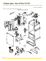
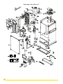
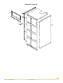
12 Spare parts - Gas 110 Eco 115 / 65 . . . . . . . . . . . . . . . . . . . . . . . . . . . . . . . . . . . . . . . . . . . . . . . . . . . . . . . . .56
4
Gas 110 Eco 115 / 65
25/01/2011 - 300014883-001-K
1 Used symbols
Caution danger
Reference
Risk
ZRefer
of injury and damage to equipment. Attention must be
to another manual or other pages in this instruction
paid to the warnings on safety of persons and equipment
manual
DHW: Domestic hot water
Important information
Information must be kept in mind to maintain comfort
Hi: Lower heating value LHV (Nett)
Hs: Higher heating value HHV (Gross)
2 Important recommendations
For a proper operating of the boiler, follow carefully the
instructions.
Any intervention on the appliance and heating equipment
must
be carried out by a qualified engineer.
The manufacturer is not liable for any improper use of the
appliance
or failure to maintain or install the unit correctly
Installation must be carried out in accordance with the prevailing
regulations, the codes of practice and the recommendations in these
instructions with the relevant certification ie: ACS, IEE regulations,
etc.
The first start-up is to be performed by your installation/
commissioning engineer.
Only original spare parts must be used.
(the user shall take care to ensure that the system is
installed by a qualified engineer).
Any work on the boiler unit is authorised only if carried out by a
qualified engineer.
Work on electrical equipment must be carried out by a
qualified
professional in compliance with the prevailing
Before commissioning, the factory settings of the appliance must be
compared with the local energy supply conditions. If the settings have
to be modified, this must be carried out by a qualified professional.
regulations.
Condensing boilers require a flue gas discharge system or a fresh air
inlet specially adapted to the method of operation. Its execution
depends on the place of installation and the building.
Keep to the polarity shown on the terminals: phase (L),
neutral
(N) and earth .
Compliance with a minimum distance between the flue gas
evacuation system in forced flue mode or the boiler with combustible
substances must comply with current regulations. At nominal output,
the temperature of the components does not exceed 85 °C.
Check that the appliance is properly set for the type of gas
used.
4
Check the seal on the gas and water pipe connections.
We shall not accept any responsibility for any damage and
disturbance arising from not following these instructions.
25/01/2011 - 300014883-001-K
Work on electrical equipment must be carried out by a
qualified
professional in compliance with the prevailing
regulations.
Installation and maintenance of the boiler must be carried out by a
qualified professional in compliance with prevailing local and national
regulations.
Gas 110 Eco 115 / 65
5
3 Description
3.1 General
Gas 100 Eco 115 / 65 boilers are floor standing gas-fired condensing
boilers fitted with an "Open Therm" control interface which enable
direct weather compensation using Remeha single and multi boilers
controls or the customer can choose to use external control options
supplied by others without affecting boiler performance.
See chapter 5.2 "Important comments on the treatment of the
Zheating
circuit".
Installation is recommended on low temperature heating installations
(Underfloor heating, radiators, ...).
They are designed for closed circuit hot water boiler rooms with a
maximum operating temperature of 90°C. However, open vented
systems can be accommodated.
3.2 Homologations
3.2.1
3.2.2
General instructions
Boiler
Gas 110 Eco 65 / Gas 110 Eco 115
No. CE
CE-0063BS3826
Type
B23 - C13 - C33 - C43 - C53 - C63 - C83 - C93
Flue gas discharge
Chimney / Flue gas outlet
Ignition
Automatic
Gas
Natural gas / Propane
Gas categories
Category
Type of gas used
Supply pressure (Gas pressure when the boiler
is not operating)
Maximum allowed on the gas valve
Gas 110 Eco 65
Gas 110 Eco 115
II2H3P
Category
Gas 110 Eco 65
Gas 110 Eco 115
6
II2H3P
Natural gas
40 mbar
Propane
60 mbar
Type of gas used
Working pressure
Minimum
Maximum
Natural gas
17 mbar
25 mbar
Propane
25 mbar
57.5 mbar
Gas 110 Eco 115 / 65
25/01/2011 - 300014883-001-K
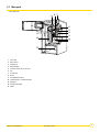
3.3 Main parts
•
Gas 110 Eco 65
7
9 8
6
5
4
3
10
11
12
C001484
2
1
13
1
Fan air inlet
2
Return sensor
3
Heating body
4
Heat exchanger
5
Combined venturi and gas valve unit
6
Fan
7
Control panel
8
Burner
9
Flow temperature sensor
10 Ignition electrode + Ionization electrode
11 Sight glass
12 Front plate exchanger
13 Siphon
25/01/2011 - 300014883-001-K
Gas 110 Eco 115 / 65
7
•
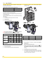
Gas 110 Eco 115
9
87
6
5
10
11
4
3
12
2
C001485
1
13
1
Fan air inlet
2
Return sensor
3
Heating body
4
Heat exchanger
5
Combined venturi and gas valve unit
6
Fan
7
Control panel
8
Burner
9
Flow temperature sensor
10 Ignition electrode + Ionization electrode
11 Sight glass
12 Front plate exchanger
13 Siphon
8
Gas 110 Eco 115 / 65
25/01/2011 - 300014883-001-K
3.4 Technical characteristics
3.4.1
Boiler
- For operation on Natural Gas or Propane (See "Switching from
Natural Gas to Propane")
- The boiler is preset in the factory to operate on natural gas G20,
20 mbar (minimum 17 mbar)
- The boiler is suitable for room sealed or open flue applications
- Single-unit heat exchanger in aluminium/silicium alloy
- Cylindrical premix burner covered in metal fibres
3.4.2
- Centrifugal fan with combustive air intake silencer for a low noise
level
- Compact gas line with zero pressure regulator, two valves and filter
- Water condensation siphon with run-off pipe
- Automatic air vent
- Mechanical manometer
- Soundproofed boiler body
- A documentation pack.
Control panel
Please read the following installation and commissioning
instructions carefully before operating your equipment. The
manufacturer shall not be liable for damage caused by the
failure to comply with these instructions and the warranty shall
no longer apply.
If work is carried out on the heating installation: assembly,
commissioning,
maintenance and repair work on the
appliance and on the heating installation must be carried
out only by a qualified heating professional.
Before installation: Ensure that the mains power supply is
isolated.
Before commissioning: Check the seal on the gas and
water pipe connections.
connection of the control panel must be carried out by
aThequalified
professional. For a proper operating of the
boiler, follow carefully the instructions.
- Power supply: 230 V (±10%) - 50 Hz
25/01/2011 - 300014883-001-K
Gas 110 Eco 115 / 65
9
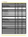
3.5 Technical data
Gas 110 Eco
65
115
CE identification no
****
Boiler specifications
Power input (Hi) - minimum/maximum G20
Power input (Hs) - minimum/maximum G20
Nominal output 50/30 °C - minimum/maximum G20
Nominal output 80/60 °C - minimum/maximum G20
kW
kW
kW
kW
12.2 - 62.0
13.5 - 68.8
13.3 - 65.0
12.0 - 61.0
17.2 - 110.2
19.1 - 122.3
18.4 - 114.0
16.6 - 107.0
m3/h
Kg/h
%
%
%
%
6.56
4.82
11.66
8.56
106
95.5
111
100
106
95.5
102.5
92.4
%
98.3
97.1
%
88.6
87.5
%
108.9
107.1
%
98.1
96.5
W
Kg/h
125
20.5/104
131
28.9/186
%
%
9.0
10.7
9.5
10.0
Pa
°C
mm
100
65
100/150
250
67.9
100/150
Gas flow rate at nominal output (15 °C - 1013 mbar)
Natural gas G20
Propane
Efficiency 75/60 °C (DIN 4702 T8) (Hi)
Efficiency 75/60 °C (DIN 4702 T8) (Hs)
Efficiency 40/30 °C (DIN 4702 T8) (Hi)
Efficiency 40/30 °C (DIN 4702 T8) (Hs)
Load and water temperature efficiency
(-100% Pn-Average temperature 70 °C) (Hi)
Load and water temperature efficiency
(-100% Pn-Average temperature 70 °C) (Hs)
Load and water temperature efficiency
(-30% Pn-Return temperature 30 °C) (Hi)
Load and water temperature efficiency
(-30% Pn-Return temperature 30 °C) (Hs)
Stand-by losses ∆T = 30K
Mass flue gas flow rate - minimum/maximum
CO2 level in flue gases
- Natural gas G20
- Propane
Available pressure at boiler outlet
Average flue gas temperature (75/60 °C)
Connection to a chimney (internal diameter)
Emission NOx (Natural gas G20) - dry 0% O2
CE-0063BS3826
mg/kWh
32
35
mg/kWh
°C
bar
mbar
mbar
21
5
90
4
175
580
31 (EN297A3)
5
90
4
230
830
Nominal water flow Pn to ∆T = 20K
m3/h
2.62
4.6
Nominal water flow Pn to ∆T = 11K
3
4.76
8.36
Emission CO (Natural gas G20) - DIN 4702 Teil 8
NOx classification
Maximum operating temperature
Maximum operating pressure
Water resistance (∆T = 20K)
Water resistance (∆T = 11K)
m /h
Water content
Flow and return connection (diameter)
Condensation water pH
Condensation water run-off (diameter)
Electrical specifications
Electrical connection
Power consumption
Degree of protection
Dimensions
Height
Width
Depth
Shipping weight
10
Gas 110 Eco 115 / 65
l
6.5
7.5
mm
1" 1/4 Male
3-5
25
1" 1/4 Male
3-5
25
V/Hz
W
DIN40050
230/50
88
IP 21
230/50
213
IP 21
mm
mm
mm
kg
1100
600
663
116
1322
600
663
133
25/01/2011 - 300014883-001-K
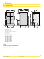
3.6 Main dimensions
3.6.1
•
Boiler self-standing
Gas 110 Eco 115 / 65
770
663
600
ØF
8
1
170
D
A
208
9
B
7
6
E
C
21
173
C001272
460
420
198
158 118
3
1
Heating outlet R 1 1/4 m
6
Heating return R 1 1/4 m
7
Condensates discharge (Ø 25 mm external)
8
Automatic air vent
9
Gas inlet R 3/4
A
Gas 110 Eco 65: 1100 mm
Gas 110 Eco 115: 1322 mm
B
Gas 110 Eco 65: 410 mm
Gas 110 Eco 115: 632 mm
C
Gas 110 Eco 65: 124 mm
Gas 110 Eco 115: 346 mm
D
Gas 110 Eco 65: 968 mm
Gas 110 Eco 115: 1190 mm
E
Gas 110 Eco 65: 152 mm
Gas 110 Eco 115: 374 mm
ØF
Forced flue connection Ø 100/150 mm
R = Thread
G = Exterior cylindrical threading, sealed by sheet gasket
(1) Basic dimension 21 mm
adjustment possible: 21 to 40 mm
25/01/2011 - 300014883-001-K
Gas 110 Eco 115 / 65
11
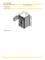
3.6.2
Boiler installed
Clear space should be left around the boiler:
- 2.5 cm each side of the boiler
(Facilitates removal of the casing)
- 70 cm in front of the boiler
- 40 cm above the boiler
•
Gas 110 Eco 115 / 65
60
1
0
3
26
C001486
A
A. Gas 110 Eco 65 = 1100
Gas 110 Eco 115 = 1322
12
Gas 110 Eco 115 / 65
25/01/2011 - 300014883-001-K
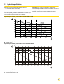
3.7 Hydraulic specifications
Depending on the flow, the following diagrams represent:
For example: Gas 110 Eco 65 with UPS 25-70 130 pump:
- the manometric heights of the heating
- loss of load in the boiler.
manometric height available at 2.61 m3/h = 4.6 mWG - 1.6 mWG = 3
mWG (i.e. 3 mbar)
For a fixed flow, the manometric height available at the boiler outlet
is obtained by taking the difference between the manometric height
of the circulator pump and the loss of load in the boiler.
2.61 m3/h corresponds to a load of 61 kW and a ∆t of 20 K
Optional 3-speed circulator pump for Gas 110 Eco 65 - UPS 25-70 130
A. Rated net head (mWG)
B.
C. Loss of load Gas 110 Eco 65
Flow rate (m3/h)
Optional 3-speed circulator pump for Gas 110 Eco 115 - UPS 25-80 130
9
C001242
A
8
7
III
T=20K
II
6
5
I
4
3
2
1
C
0
0,0
0,5
1,0
1,5
2,0
2,5
3,0
3,5
4,0
4,5
5,0
5,5
B
A. Rated net head (mWG)
B. Flow rate (m3/h)
C. Loss of load Gas 110 Eco 115
25/01/2011 - 300014883-001-K
Gas 110 Eco 115 / 65
13
4 Control and safety equipment
4.1 Control panel
4.1.1
General
The boiler is supplied with a standard set of defaults pre-programmed
for normal operation but can be tailored by the Engineer to suit most
site conditions. These values are set and read using the built in
control panel or with a notebook computer (with an interface and
software available on request).
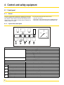
4.1.2
For security the control has three levels of access:
- User level - free access
- Service level - access with service code by qualified personnel
- Factory level - access by PC with factory code (Remeha only).
Layout of the control panel
"code"-display
Indicates on user level:
Operating mode: only one digit Setting mode: digit with dot Read-out mode: digit with flashing dot Shut-off mode: letter B
Forced full load: letter G
Forced part load: letter H
Additional indication on service level:
Fan speed mode: alternate half digit '
Indicates:
Temperatures, settings, fault codes (flashing digits), shut-off codes (flashing dots)
x-display
Failure mode: flashing digit reset-key:
To reset after a lockout condition
Key "r":
Program function: key to select the required mode
Key "w":
Program function: key to select the required program within the selected mode
14
Key w + Symbol v:
Key "l":
Switch function: burner switch HTG (manual override)
Program function: key to save the settings
Key "l" + Symbol q
Switch function: burner switch DHW (manual override)
Key [+]:
Program function: to select a higher setting
Key [+] + Symbol u
Key [-]:
Key [-] + Symbol n:
Switch function: pump manual override
Program function: to select a lower setting
Switch function: manual override (hand/auto)
Gas 110 Eco 115 / 65
25/01/2011 - 300014883-001-K
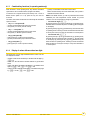
4.1.3
Combined key functions (in operating mode only)
When the boiler is in the operating mode, keys with the illuminated
symbols above have a double function (Program and Switch).
To use them for a Program function press the key once - and for a
Switch function (either on or off) press the key and hold for
5 seconds.
The status of the switch function will be confirmed by the illuminated
symbol as follows:
- (symbol) not illuminated: HTG under normal control.
Manual override will stay active until deactivated, even if power is
switched off and then restored.
NOTE: In the Switch function, (in order to protect the boiler and the
installation) the flow temperature cannot exceed it’s pre-set
maximum. It is also not possible to change any parameters.
• Key "w" and symbol v:
- (symbol) not illuminated: HTG under normal control
- red (symbol) on: HTG off (manual override)
• Forced mode "high" (G>>)
By pressing the keys "r" and [+] simultaneously in operating mode,
the boiler will burn at maximum power. The letter G will now appear
on the display.
• Key "l" and symbol q:
- (symbol) not illuminated: DHW under normal control
- red (symbol) on: DHW off (manual override)
By pressing the keys [+] and [-] simultaneously, the boiler will return
to operating mode. Following a manual override the boiler will return
to normal (auto control) if no keys are used within a 15 minute period.
• Key [+] and symbol u:
- green (symbol) on: continuous pump operation
- (symbol) not illuminated: pump under boiler control
• Forced mode "low" (H>>)
By pressing the keys "r" and [-] simultaneously in operating mode,
the boiler will burn at minimum power. The letter H will now appear
on the display. By pressing the keys [+] and [-] simultaneously, the
boiler will return to operating mode. Following a manual override the
boiler will return to normal (auto control) if no keys are used within a
15 minute period.
• Key [-] and symbol n:
- green (symbol) on: HTG on (manual override)
4.1.4
Display of values with more than two digits
The display has only two digits available therefore values over this
are displayed as follows:
- negative values will be indicated by a dot behind the last digit e.g.
= -10
- values from 00 to 99 will be indicated without any punctuation
marks
- values from 100 to 199 will be indicated by a dot between both
digits e.g. = 100, = 110, & = 199.
- values from 200 to 299 will be indicated by a dot behind every digit
e.g. = for 200, = 210, = 299.
25/01/2011 - 300014883-001-K
Gas 110 Eco 115 / 65
15
4.2 Flow diagram control system
Press the "r"-key for the menu
Press the "w"-key for the menu
"code"-display
Operating mode
Z§ 4.3
Setting mode, user level
Z§ 4.5
Only digit or letter
- &,G,H,B
Flow temperature or shut-off code
Digit or letter with fixed dot
Flow temperature set-point
)
Pump run on time HTG
DHW temperature set-point
*
Boiler control setting
M
Setting mode, service level
Z§ 4.6
Base point internal compensation slope
Service engineer level only:
?
+
0
-
.
/
1
2
3
4
5
6
7
;
8
=
@
16
x-display
Flow temperature set-point during forced part load
High limit temperature set-point
Fan speed at full load (HTG)
Fan speed at part load (HTG and DHW)
Modulation start point ∆T (F/R)
Interface selection (control option)
DHW cut-in ∆T
Fan speed at full load (DHW)
Intern
N/a
N/a
Forced part load time after start (HTG)
Fan speed at start
DHW control stop or boiler modulation set point (based on parameter )
DHW control mode
N/a
HTG cut-in ∆T (based on return)
N/a
Boiler type
Intern
Maximum delay time
Start point for 0 V analog signal
End point for 10 V analog signal
Intern
Gas 110 Eco 115 / 65
25/01/2011 - 300014883-001-K
Read-out mode
Digit or letter with flashing dot
Z§ 4.7
Actual flow temperature
)
Actual return temperature
Actual DHW temperature (with sensor)
Actual outdoor temperature (only if outdoor sensor fitted)
N/a
?
Flow temperature (set point)
Actual heat demand status
Calculated HTG cut-in temperature
8
Actual flow temperature rise
*
N/a
Service engineer level only:
Speed mode
Alternate half digit '
Z§ 4.8
Failure mode
Fan speed
Flashing digit
Z§ 4.9
Failure code
Operating code during failure
Flow temperature during failure
!
Return temperature during failure
"
DHW temperature during failure
#
N/a
4.3 Operating mode (N>>)
During operation the "code"-display shows the status (position in
cycle) of the boiler, whilst the x-display indicates the actual flow
temperature.
Code
!
"
#
$
%
&
B
G
H
The digits or letters in the code-display have the following meaning:
Description
Standby: there is no heat demand from control system
Pre-purge: before start-up, the boiler is purged for 4.2 seconds
Post-purge: when the heat demand has been met, the fan continues to operate for another 10 seconds
Ignition: ignition is activated for 2.4 seconds while the gas valve is opened
HTG mode: the boiler operates in the HTG mode
DHW mode: the three way valve or DHW pump activated
Internal check
Normal control stop during HTG (flow temperature > set-point + 5 °C)
HTG pump run on
DHW pump run on or for three way valve option, HTG pump run on with valve open to DHW (max. 5 minutes)
Normal control stop during DHW (flow temperature > set point DHW + DHW control stop set point + 5 °C)
Shut-off mode
Forced full load
Forced part load
25/01/2011 - 300014883-001-K
Gas 110 Eco 115 / 65
17
4.4 Shut-off mode (B<<)
During shut-off mode condition the "code"-display will show a B,
whilst the x-display indicates the cause with two flashing dots.
Code
B)
B)+
B)
B)
B
B
Table below details cause of shut-off mode.
Description
Maximum acceptable flow temperature rise exceeded. The boiler will shut off for ten minutes, then restart. Should the flow
temperature conditions remain the same after 5 attempts, this code will be recorded as a shutdown failure. Boiler will not
lockout.
Contacts of the external interlock have opened during heat demand. The boiler will shut off for 120 seconds. Should the contacts close again during heat demand, the boiler will wait the remaining time from the 120 seconds before attempting a
restart.
Internal check on fan speed. After 5 attemps, the boiler will lockout. This code will be recorded.
Internal check on fan speed. After 5 attemps, the boiler will lockout. This code will be recorded.
Maximum temperature difference between flow and return exceeded. The boiler will shut off for 150 seconds, then restart.
Should the temperature difference conditions remain the same after 10 attemps, this code will be recorded as a shut-down
failure. Boiler will not lockout.
One or several adjusted parameters out of range including some factory defaults which should not have been changed.
Check and reset parameters:
- Press the "reset"-key immediately followed by pressing the "r"-key for about 12 seconds,
- "code"-display shows 7,
- use [+] and [-] -keys to enter correct boiler parameter
(7=! for Gas 110 Eco 115, 7=#! for Gas 110 Eco 65)
- press "l"-key to confirm settings,
- check parameter settings and change were needed or desired.
NOTE: Shut-off mode is a normal boiler operating function and does
not represent a boiler failure.
However, this may indicate a system problem, an internal boiler
check or an incorrect parameter setting.
4.5 Setting mode user level (<>>)
Code
)
*
;
Description
Flow temperature set point
Pump run on time HTG
Setting range
-& °C
= pump run on 10 seconds
-"= pump run on in minutes
DHW temperature set point
-$" °C (only with sensor)
Boiler control setting
Control mode (modulating-on/off etc.)
Base point internal compensation slope
N/a
NOTE: Changing code ) and code * should only be on design
engineers advice.
18
Gas 110 Eco 115 / 65
Preset
%
""
25/01/2011 - 300014883-001-K
4.5.1
Flow temperature set point ()
The required flow temperature is adjustable from 20 to 90 °C.
4.5.2
Pump run on time HTG ())
Pump run on time can be adjusted (Please refer to installation
contractor)
- Press the "r" -key until the digit (with dot) appears in the
"code"-display.
- Press the "w"-key until the digit ) (with dot) appears in the
"code"-display.
- Set the required value, using the [+] and [-] -keys.
Code
)
)
x
<N
25/01/2011 - 300014883-001-K
- Press the "l"-key to store the new value (value will flash twice).
- Press the "reset"-key to return to operating mode.
NOTE: For continuous pump operation use manual override,
ZSee chapter 4.1.3.
Description
Pump runs on for 10 seconds
Pump runs on for 1 to 15 minutes (NN= to ")
Gas 110 Eco 115 / 65
19
4.5.3
DHW temperature set-point ( )
The DHW temperature is adjustable from 20 to 75 °C (factory
default 55 °C). Only with DHW priority sensor.
- Press the "r" -key until the digit (with dot) appears in the
"code"-display.
- Press the "w"-key until the digit (with dot) appears in the
"code"-display.
- Set the required value, using the [+] and [-] -keys.
4.5.4
- Press the "l"-key to store the new value (value will flash twice).
- Press the "reset"-key to return to operating mode.
NOTE: there are further adjustments available on service level.
Please refer to your service engineer or contractor.
ZSee chapter 4.6.7.
Boiler control setting (*)
The boiler is factory set to option (HTG modulating or on/off
with DHW on).
To change the control option:
- Press the "r" -key until the digit (with dot) appears in the
"code"-display.
- Press the "w"-key until the digit * (with dot) appears in the
"code"-display.
- Set the required X and Y values as listed below in using the
[+] and [-] -keys.
- Press the "l"-key to store the new value (value will flash twice).
- Press the "reset"-key to return to operating mode.
x-display
First segment N>
!
"
Second segment >O
"With the ""code""- display showing * - the x-display will indicate
the method of boiler control in the first segment N> and the option
to turn the HTG and DHW on or off in the second segment >O". By
using codes from the table below a series of control options are
available.
Example: NO
- Boiler enabled internal modulation with booster on * - HTG
and DHW on (as default)
! - Analog signal 0 -10 V on temperature - HTG on and DHW
off
- Boiler high/low - HTG off and DHW on
Description
Boiler control option
Boiler enabled internal modulation with booster on *
Boiler high/low
Boiler enabled internal modulation with booster off *
Analog signal 0 - 10 V on temperature
Analog signal 0 - 10 V on output %
Operation mode
HTG and DHW off
HTG and DHW on
HTG on and DHW off
HTG off and DHW on
* NOTE: boiler setting * and
20
have the same function
Gas 110 Eco 115 / 65
25/01/2011 - 300014883-001-K
4.6 Setting mode service level (<)
(only for the qualified service engineer with product knowledge).
To prevent accidental, unauthorised access by non-qualified persons
the control system requires an input code to gain access to the
second level of boiler control.
- Press the "r" - and "w"-keys simultaneously and hold. The
"code"-display now shows a letter C with a random number in the
x-display.
- While holding both keys pressed, set the x-display to ,
using the [+] or [-] - keys and press the "l"-key.
Code
+
- The display will flash twice confirming acceptance of the access
code.
- Release the keys and C will disappear from the display.
You are now in the service mode.
WARNING: changing factory defaults without reference to the tables
contained in this manual may result in incorrect operation.
- To delete the service code press the "reset"-key once
- If no keys are pressed over a 15 minute period the service code will
delete automatically.
Preset
Description
Setting range
Flow temperature set point during
forced part load
-& °C
$&
&-(= 110 °C)
(= 100)* (= 100)*
Gas 110 Eco 65: -# hundreds
Gas 110 Eco 115: -$ hundreds
"
$
"
"
"
"
$
"
"
High limit temperature set point
Fan speed at full load (HTG)
Fan speed at part load (HTG and
DHW)
Gas 110 Eco 65 Gas 110 Eco 115
-$ hundreds
Modulation start point ∆T (F/R)
"-
°C
Interface selection (control option)
external interface
internal (Modulating controls only)
-"read 1 - 5 °C
#read 10 °C
$read 15 °C
%read 20 °C
+
DHW cut-in ∆T
0
Fan speed at full load (DHW)
Gas 110 Eco 65: -# hundreds
Gas 110 Eco 115: -$ hundreds
-
Intern
May not be changed!
N/a
.
/
N/a
$&
(= 100)* (= 100)*
Forced part load time after start
(HTG)
-" minutes
Fan speed at start
May not be changed!
"
"
2
DHW control stop or boiler
modulation set point (based on
parameter )
-
3
DHW control option
4
= Three way valve (port A = HTG, port B = DHW)
= DHW pump
= inverted three way valve (port A = DHW, port B = HTG)
Variable speed pump
N/a
6
N/a
1
5
7
;
8
=
@
HTG cut-in ∆T
°C
(= -10 °C) - °C
Boiler type
May not be changed!
Intern
May not be changed!
Maximum delay time
Start point for 0 V analog signal
End point for 10 V analog signal
-&& minutes
" (= -50 °C) - " °C
"-(= 299) °C
Intern
#!
"
(= 103)*
(= 103)*
!
"
(= 100)* (= 100)*
* NOTE:
ZSee chapter 4.1.4 for values over two digits
25/01/2011 - 300014883-001-K
Gas 110 Eco 115 / 65
21
4.6.1
Flow temperature set point during forced part load ()
Adjustable from 20 °C to 90 °C.
4.6.2
This value will prevent the flow temperature exceeding this
temperature during the part load time.
High limit thermostat ()
Adjustable from 90 °C to 110 °C ().
This value sets the high limit temperature at which the boiler will shut
down in a lock out condition requiring manual intervention.
4.6.3
* NOTE: this parameter will have an effect on the minimum flow rate
requirement
ZSee chapter 5.3.
Fan speed at full load HTG (?)
Adjustable from 18% to 100% output (= approx. 1300 to 7000 rpm for
the 115 and 1200 to 6000 for the 65). This value sets the maximum
output of the boiler.
4.6.4
Fan speed at part load (HTG and DHW - )
Adjustable from 18% to 100% output (= approx. 1300 to 7000 rpm for
the 115 and 1200 to 6000 for the 65). This value sets the minimum
output of the boiler.
4.6.5
Starting point modulation ()
Adjustable from 5 °C to 30 °C.
This value sets the flow/return ∆T point at which the control
modulation begins. If the ∆T continues to rise, at 40 °C the boiler will
be at minimum output (parameter ), at 45 °C the boiler will shut off
(code #)
ZSee chapter 4.4.
4.6.6
The factory default should be correct for most installations. Changing
this value should only be carried out on advice from the service
engineer. Do not change the factory default for the minimum output
(parameter ), in cases of minimal flow.
NOTE: Installations with low flow problems would benefit by reducing
this set point to force modulation to begin sooner and minimise boiler
off time.
Interface selection ()
Adjustable or .
This value sets the control option.
for standard external control.
for Open Therm option.
22
Gas 110 Eco 115 / 65
25/01/2011 - 300014883-001-K
4.6.7
DHW cut-in temperature (+)
Adjustable from °C to °C (8 steps).
- The thermostat determines the DHW demand.
ZSee chapter 4.6. Table
Boiler modulation during continuing DHW demand
DHW demand
Sensor and thermostat:
With sensor:
- The boiler will modulate when the flow temp equals the DHW set
point + DHW control stop set point (parameter 2) i.e. 55 + 20 =
75.
- The boiler carries out a control stop at a flow temp of 80 °C
(modulation point + 5 °C), the display initially shows &%,
reducing to &$".
- The DHW cut-in temperature sets the below this control stop.
Cut-in temperature =
DHW set point (55) + DHW control stop set point (parameter 2) +
5 - parameter + (5), i.e. 55 + 20 + 5 - 5 = 75
- The DHW demand is satisfied when the DHW temperature equals
the DHW set point temp (parameter ) + 5 °C.
- The DHW cut-in temperature sets the ∆T below this end point for
DHW demand.
Cut-in temperature =
DHW set point (55) + 5 - parameter + (5), i.e. 55 + 5 - 5 = 55 °C.
With thermostat:
4.6.8
Fan Speed at DHW full load (0)
Adjustable from 18% to 100% output (= approx. 1300 to 7000 rpm for
the 115 and 1200 to 6000 for the 65).
Parameters , - - - and . are factory set and must not be
changed
This value sets the maximum output of the boiler.
4.6.9
Forced part load time after start (HTG only - /)
Adjustable from to " minutes.
This value sets the period of time the boiler will stay on part load at
start up during which time the flow temp is limited by part load temp
set point (Parameter )
Changing the factory default should only be carried out on advice
from the service engineer.
NOTE: When using an external analog (0 -10 V) or 2 wire modulation
input, the factory default should be changed to .
Parameter 1 factory set must not be changed
4.6.10 DHW control stop set point (2)
Adjustable from °C to
°C.
ZSee chapter 4.6.7.
4.6.11 DHW control option (3)
This value sets the DHW control option.
Three way diverting valve (port A - HTG and port B - DHW)
DHW pump
Inverted three way diverting valve (port B - HTG and port A
- DHW)
Parameter 4 not applicable
4.6.12 HTG cut in temp (5)
Adjustable from (-10) °C to °C.
i.e. 60 - 3 = 57 °C
This value sets the ∆T below actual return temp at the moment of
control stop during HTG demand.
A control stop occurs when the flow temp equals the flow temp set
point +5 °C.
If this takes longer than the maximum delay time (parameter ;), the
boiler will restart (unless flow temperature exceeds flow temperature
set point).
Parameter 6 not applicable
HTG cut in temperature = actual return temperature at the moment of
control stop (e.g. 60) - parameter 5 (3)
4.6.13 Boiler type (7)
Factory default must not be changed.
ZSee chapter 4.4 Shut-off mode, B
25/01/2011 - 300014883-001-K
Parameter : factory set must not be changed
Gas 110 Eco 115 / 65
23
4.6.14 Maximum delay time (;)
Adjustable from to && minutes.
This value sets the maximum off time following a control stop. The
minimum off time is preset to a fixed value (150 seconds).
A combination of both values is used to prevent hunting taking place.
4.6.15 Start and end point analog signal ( and =)
Start point (0 V): adjustable between " (-50) °C and +" °C.
This value sets the required flow temp at 0 V signal input (restricted
by the minimum flow set point).
End point (10 V): adjustable between + " °C and (+299)
°C.
This value sets the required flow temp at 10 V signal input (restricted
by the maximum flow set point).
NOTE: These settings are only applicable when boiler control
operation parameter (*) has the N value set to !.
24
Gas 110 Eco 115 / 65
25/01/2011 - 300014883-001-K
4.7 Read-out mode (<)
To check boiler set points and values.
Using the "r" - key, press repeatedly until (flashing dot) appears
in the "code"-display. Then select the required code ), or etc. using the "w"-key.
Code
)
?
Description
Read-out (example)
%
Actual flow temperature
$
Actual return temperature
N/a
%
Flow temperature (set point)
N= demand
N= no demand
Actual heat demand status
Calculated HTG cut-in temperature
*
"
Actual outdoor temperature (only with sensor connected)
"%
Actual DHW temperature (only with sensor connected)
#$
Actual flow temperature rise [0.1 °C/sec]
N/a
4.8 Fan speed mode (')
Using the "r" - key, press repeatedly until "code"-display shows
alternate flashing half digits.
Code
(
Description
Fan speed
Fan speed
The value in the x-display shows the actual fan speed using two
alternate double digits as table:
Example 7000 r/m
$ hundreds
units
4.9 Failure mode (N)
To check the latest failure with the accompanying operating codes
and relevant temperatures.
Using the "r" - key, press repeatedly until (flashing digit) appears
in the "code"-display.
Code
!
"
#
x
$
Then select the required code ,
key and read off the relevant value.
or ! etc. using the "w"-
Description
Display of failure code
§ 8.2
Z
Operating mode during failure
"
!
#
Flow temperature during failure
Return temperature during failure
DHW temperature during failure
N/a
Example as above:
Failure code $ indicates the return temperature sensor failed
during HTG operation ( ), at a flow temperature of 53 °C, a
return temperature of 40 °C and DHW temperature of 60 °C.
25/01/2011 - 300014883-001-K
Gas 110 Eco 115 / 65
25
5 Installation
5.1 Statutory terms and conditions of installation and maintenance
The complete installation must comply with the current editions of
relevant British Standards and codes of practice, including the latest
local and national regulations for this type of equipment.
All gas appliances must, by law, be installed by a competent qualified
engineer holding the relevant qualifications and certificates (for
example ACS and IEE regulations.)
IMPORTANT:
The Broag-Remeha 110 is a CE certified appliance and must not
therefore be modified or installed in any way contrary to these
"Installation and Maintenance Instructions". These manufacturer's
instructions must NOT be taken as overriding statutory obligations.
Failure to install this appliance correctly could result in an unsafe
condition which can lead to prosecution. It is your own interest and
that of safety to ensure that the law is complied with.
26
Gas 110 Eco 115 / 65
25/01/2011 - 300014883-001-K
5.2 Important comments on the treatment of the heating circuit
Water treatment
-
Use untreated tap water only to fill the central heating system.
The pH value of the system water must be between 6 and 9.
Chloride content <20 mg/l
Conductivity <500 µS/cm at 25 °C
In case inhibitors are being used, please follow the instructions
given.
If used correctly water treatment can improve the boilers efficiency
and increase the anticipated life expectancy of the boiler. For further
information a special document "Remeha water quality regulations"
is available on request. The regulations mentioned in this document
must be followed.
BETZ DEARNORN Ltd
Sentinal
Foundry Lane
Widnes
Cheshire WA8 8UD
Tel.: 0151 424 5351
Fax.: 0151 420 5447
Cold feed and expansion tank height for open
vented systems
As most systems contain a variety of metals, it is considered good
practice to provide some form of water treatment in order to prevent
or reduce the following:
We recommend the boiler is installed on a closed (pressurised)
system wherever possible with a minimum operating pressure of
0.8 bar However, open vented systems can be accomodated as
follows: the cold feed and expansion tank heights for all open vented
systems must comply with the requirements laid down in the Health
and Safety Executive publication (latest edition).
-
The Gas 110 Eco 115 / 65 series boilers require a minimum static
head of:
- 5 m for Gas 110 Eco 115,
- 3 m for Gas 110 Eco 65.
metallic corrosion
formation of scale and sludge
microbiological contamination
chemical changes in the untreated system water.
All scale deposists, however small, will reduce
efficiency
of the boiler and should be prevented.
the
Suitable chemicals and their use should be discussed with a
specialist water treatment company prior to carrying out any work
(environmental aspects, health aspects). The specification of the
system and manufacturers recommendations must be taken into
account, along with the age and condition of the system.
New systems should be flushed thoroughly to BS 7593 (1992) to
remove all traces of flux, debris, grease and metal swarf generated
during installation. Care to be taken with old systems to ensure any
black metallic iron oxide sludge and other corrosive residues are
removed, again by flushing, ensuring that the system is drained
completely from all low points.
Please ensure that the new boiler plant is not in circuit when the
flushing takes place, especially if cleansing chemicals are used
to assist the process.
It is important to check the inhibitor concentration after installation,
system modifications, filling the system and every service in
accordance with these instructions.
For the correct dosage and the suitability of inhibitors for use with our
boilers and for further information on water treatment or system
cleaning we advise direct contact with either of the following
companies:
FERNOX, Cookson Electronics or WESTERN ENVIRONMENTAL
Forsyth Road
Western House
Sheerwater
Britonwood Trading Est
Woking
Knowsley
Surrey GU21 5RZ
Merseyside
Tel.: 0870 6015000
L33 7YP
Fax.: 01799 522280
Tel.: 0151 546 5777
@ fernox.com
Email.: sales :
Web site.: www.fernox.com
or
25/01/2011 - 300014883-001-K
For operation in open vented systems:
- parameter (flow temperature set-point) must be set to 75,
- parameter (boiler modulation start point) must be set to 15,
- parameter (high limit temperature set-point) must be set to 95.
Safety valve
A safety valve should be fitted in accordance with the relevant British
Standard.
System pump
The boiler must be installed on a fully pumped system.
Installing the boiler in existing installations
- Remove sludge from the installation,
- Clean the installation with a universal cleaner to eliminate debris
from the appliance,
- Thoroughly flush the installation until the water runs clear and
shows no impurities,
- Protect the installation against corrosion and frost with an inhibitor
and an anti-freeze.
The boiler must be used only in closed circuit heating installations. If
you have underfloor heating, the installer must install a safety
thermostat with manual reset to prevent overheating. For an
underfloor heating circuit without system insulation, only oxygen tight
heating pipes must be used. If the plastic pipe manufacturer
recommends a chemical additive, it is necessary to be particularly
careful that there are no adverse effects on the aluminum or
aluminum alloy content of components. For floor heating systems
with pipes that are not oxygen tight, the system must be insulated
(heat exchanger). In this case, the floor circuit must be protected
separately (Expansion vessel, Safety valve).
A minimum water level safety device is not necessary. Protection is
ensured by the control unit.
Gas 110 Eco 115 / 65
27
Minimum water flow
The maximum temperature difference between flow and return, and
the maximum rate of rise of the flow temperature and boiler block
temperature are limited by the boiler modulating controls, as a result,
the boiler is virtually unaffected by low water flow, however for a
continuous supply of heat the boiler requires a minimum flow of
30% of the nominal flow at the relevant design.
Otherwise, the minimum required flow is:
- 240 l/h for Gas 110 Eco 65,
- 350 l/h for Gas 110 Eco 115.
In the event of excessive pump noise
Run-off noise may occur on installations with a direct heating circuit,
fitted with thermostatic valves, under certain conditions of use when
the hydraulic systems are not perfectly balanced.
If this is the case, we recommend fitting a preset differential valve (200-250 mbar) between the out pipe and the return pipe on the
heating installation.
Location of the installation
Gas 110 Eco 115 / 65 boilers must be installed in a frost-free
environment.
In order to avoid damage to the boiler, it is necessary to
prevent
the contamination of combustion air by chlorine
and/or fluoride compounds, which are particularly
corrosive. These compounds are present, for example, in
aerosol sprays, paints, solvents, cleaning products,
washing products, detergents, glues, snow clearing salts,
etc.
Therefore:
- Do not pull in air evacuated from premises using such
products: hairdressing salons, dry cleaners, industrial
premises (solvents), premises containing refrigeration
systems (risk of refrigerant leakage), etc.
- Do not stock such products close to the boilers.
If the boiler and/or peripheral equipment are corroded by
such chloride or fluoride compounds, the contractual
guarantee cannot be applied.
The warranty does not apply to damage to the boiler caused by these
instances. If the heating device is installed in residential premises
where people are present all the time, it is necessary to use a
concentric ambient air inlet / combustion gas evacuation installation.
When installing the boiler, it is necessary to comply with degree of
protection IP21.
These actions must be carried out by a qualified engineer
holding
the relevant qualifications and certificates (for
example ACS and IEE regulations).
C001243
Installation must be carried out in accordance with the prevailing
regulations, the codes of practice and the recommendations in these
instructions.
Poor adjustment of the differential valve may cause a
continuous
increase in the return of water to the boiler.
If there are particular requirments for silent running, it is a good idea
to fit a differential pressure regulator (setting 100 -150 mbar).
: Radiator
28
The gas shut off valve should be located on the back of the boiler.
Pipe diameters must be defined in accordance with the current
editions of relevant British Standards and codes of practice, including
the latest local and national regulations for this type of equipment.
To prevent damage caused by overpressure on the gas valve, the
gas supply valve must be closed before carrying out the pressure test
on the gas supply pipe. Decompress before reopening the valve.
In old gas networks, we recommend fitting a gas filter with a large
surface area.
Gas 110 Eco 115 / 65
25/01/2011 - 300014883-001-K
5.3 Water discharge connection
Discharge condensation water directly into the main drain. Given the
degree of acidity (pH 2-5), use only plastic materials to make the
connection. Make the connection to the main drain with a visible flow
connection.
The discharge duct must have a minimum gradient of 50 mm/m. The
discharge of condensation water via the gutter is not authorised, given
the risk of frost and the damage to the materials usually used for gutters.
5.4 Room sealed installations
It is unnecessary to provide separate combustion air to the room/
compartment as this is supplied direct to the boiler via the concentric
or eccentric system and the room sealed horizontal or vertical
terminal unit.
Additional ventilation will be required to the room/compartment in
accordance with the British Standards (compartment ventilation).
For maximum flue/air inlet length
ZSee chapter 6.1.2
For the United Kingdom: Comply with latest British standards.
Ref BS 5440 - 2: Specification for installation and maintenance
of ventilation for gas appliances not exceeding 70kW (1st, 2nd
and 3rd family gases).
Ref BS 5440 - 1: Specification for installation of gas appliances
to chimneys and for maintenance of chimneys not exceeding
70kW (1st, 2nd and 3rd family gases).
Ref BS 6644: Specification for installation of gas-fired hot water
boilers of rated inputs between 70kW to 1.8 kW (net) (2nd and
3rd family gases).
Ref IGE/UP/10: Installation of flued gas appliances in industrial
and commercial premises.
For installations where supply and discharge points are in two
different pressure zones (eccentric only), please contact Broag
Technical Dept. for further details and advice.
ZSee chapter 6.1.1
NOTE: the boilers can be installed on a flue dilution system, but must
have a total flue break to avoid boiler controls being affected by the
dilution fan pressures. For full details, please contact Broag.
5.5 Checking the gas inlet (Boiler only)
These actions must be carried out by a qualified engineer.
`
Check the leak tightness of the gas inlet, including the gas
valves.
`
Open all the stop valves on the gas inlet.
`
Empty the gas inlet.
Maximum authorised pressure on the gas valve: 60 mbar. In the
event of higher control pressures, disconnect the boiler from the
gas inlet at the threaded connection to the gas stop valve.
Closing the gas stop valve is not sufficient.
25/01/2011 - 300014883-001-K
Gas 110 Eco 115 / 65
29
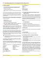
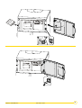
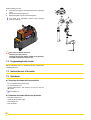
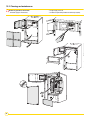
5.6 Reversal of the direction the control panel access door opens
As standard, the control panel access door opens to the left. To open
the control panel access door to the right, proceed as follows:
2
3
4
2
C001494
1
•
Modify the direction of the door handle
C001
250
7
5
7
5
30
6
Gas 110 Eco 115 / 65
25/01/2011 - 300014883-001-K
1
2
C001496
C001495
3
25/01/2011 - 300014883-001-K
Gas 110 Eco 115 / 65
31
C001497
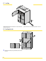
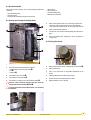
5.7 Levelling
Level the boiler by turning the adjustable feet. To adjust, take the load
off the foot using a lever.
(1) Basic dimension 21 mm. adjustment possible: 21 to 40 mm.
5.8 Handling the boiler
2
C001254
1
32
The boiler can be lifted by using 2 tubes Ø3/4" placed as shown
in the view.
Gas 110 Eco 115 / 65
25/01/2011 - 300014883-001-K
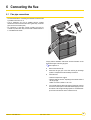
6 Connecting the flue
6.1 Flue pipe connections
C001488
- The horizontal sections on the flue gas side will be constructed with
a gradient to the boiler of 3 %.
- Type C appliances can only be installed with the systems
mentioned in these technical instructions (particularly concentric
pipes, terminal connection parts).
- As connections of type B23 chimney conduits and type C53
conduits are pressurised, they must be either installed outside or
in a ventilated brick sheath.
Comply with the installation instructions and the information on the
authorised lengths of the flue gas pipes.
ZSee chapter 6.1.2
`
Remove the anti-dust cap.
`
Mount the flue gas pipe or the fresh air/flue gas discharge
system in compliance with the assembly instructions.
`
Check the seal.
- Static test overpressure: 1000 Pa
- Maximum leak rate: 50 l/hm2 depending on the internal surface of
the flue gas pipe
AØ80 = 0.25 m2/m, AØ100 = 0.31 m2/m
`
25/01/2011 - 300014883-001-K
On concentric flue gas discharge systems (forced flue), the C02
level in the annular space in the measurement piping can also
be checked. The flue gas discharge system is considered leakproof if the measured CO2 level is lower than 0.2%.
Gas 110 Eco 115 / 65
33
6.1.1
Classification
2
1
5
6
3
7
4
7
1
Flue type C13:
Air/flue gas connection by means of concentric pipes to a horizontal
terminal (so-called forced flue)
2
Flue type C33:
Air/flue gas connection by means of concentric pipes to a vertical
terminal (roof outlet)
3
Flue type C93:
Air/flue gas connection by concentric pipes in the boiler room and
single pipes in the chimney (combustive air in counter current in the
chimney)
- Only factory components are authorised for connecting
the boiler and the terminal.
- The clear section must comply with the standard.
- The chimney must be swept before the installation of the
evacuation conduit.
2
C001246
2
Flue type B23P:
Cascade installation
Optional accessories:
Flue damper (depending on flue design)
For information about the connection to the electrical terminal block,
refer to the instructions delivered with package AM3
34
4
Flue type C93:
Air/flue gas connection by concentric pipes in the boiler room and
single "flex" in the chimney (combustive air in counter current in the
chimney)
5
Flue type C53:
Air and flue gas connection separated by means of a bi-flow adapter
and single pipes (combustive air taken from outside)
6
Flue type B23P:
Chimney connection (combustive air taken from the boiler room)
Gas 110 Eco 115 / 65
25/01/2011 - 300014883-001-K
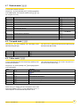
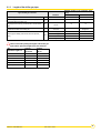
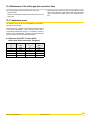
6.1.2
Lengths of the air/flue gas pipes
Maximum length of the connection pipes
(metre)
Type of air/flue gas connection
Diameter
Gas 110 Eco 65
Gas 110 Eco 115
Concentric pipes connected to a horizontal terminal (Alu)
C13
100/150 mm
9
5.9
Concentric pipes connected to a vertical terminal (Alu)
C33
100/150 mm
11.5
9.4
Concentric pipes in the boiler room
Single pipes in the chimney (combustive air in counter current)
(Alu)
C93
110/150 mm
110 mm
16
10
Bi-flow adapter + Separate single air/flue gas pipes
(combustive air taken from outside) (Alu)
C53
100/150 mm on
2x100 mm
23
Air: 11
flue gases: 5
80 mm (rigid)
23.5
23.5
Chimney (rigid or flexible) (combustive air taken in the premises)
(PPS)
B23P
110 mm (rigid)
-
-
80 mm (Flexible)
21
21
110 mm (Flexible)
-
-
Lmax is measured by adding the lengths of the air/flue gas
pipes
and the equivalent lengths of the other elements:
Alu
Equivalent length in m
Diameter
Diameter
100/150 mm
100 mm
Elbow 87°
1.9
5.0
Elbow 45°
1.2
1.2
Elbow 30°
/
/
Elbow 15°
/
/
Inspection T
3.3
5.3
Right inspection tube
0.5
0.5
25/01/2011 - 300014883-001-K
Gas 110 Eco 115 / 65
35
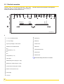
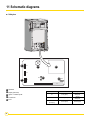
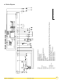
6.2 Electrical connection
T
T
T
L L1
N 230V
230V
N
L
L
15 16 17 18 19 20 21 22 23 24 25 26 27
Extn
Sensor
System
Pump
7 8 9 10 11 12 13 14
Internal
Sensor
5 6
Flow
Sensor
3 4
DHW
Sensor
1 2
Outside
Sensor
A
N
Fuse 6.3AT
BUS
GND +
The earth connection shall comply with current regulations.
DHW
pump/ Valve
The Gas 110 Eco 115 / 65 must have a fixed 230V - 50Hz single
phase mains supply. It must be powered by a circuit containing a
double pole switch with an opening distance 3 mm.
N L L NN
1 2 3 4 5 6 7 8 9 10111213141516171819
202122232425262728293031323334353637
B
300014906-001- C
A.
1
2
3
4
5
6
7
8
9
B. Optional Rematic connectors
0 - 10 V or modulating controller
On / Off (1st stage)
High / low (2nd stage) or outdoor sensor
DHW sensor or volt free thermostat
N.A.
15
16
17
18
20
21
22
23
24
10 Safety interlock (10 - 14)
25
11 N.A.
34
12
35
13
N.A.
14 Safety interlock (10 - 14)
15
16 230 V Signal
17
18
19
20
21
22
23
24
36
37
System pump
DHW pump
Outdoor sensor
DHW sensor
Flow temperature sensor
Internal sensor
Extension timer
ZSee Rematic fittings instructions for full details.
DHW diverting valve or pump (max. 1 Amp)
Boiler pump or system pump (max. 1 Amp)
Common alarm volt free (opens on failure)
Boiler run volt free (closes on run)
25
26 Power supply
27
F3 6.3 A fuse
36
Gas 110 Eco 115 / 65
25/01/2011 - 300014883-001-K
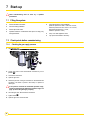
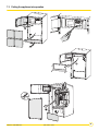
Access to the electrical connections
4
3
1
C001489
2
`
Open the panel flap.
`
Unscrew the 2 mounting screws at the back of the top panel.
Lift and tilt the back of the top panel.
`
Unscrew the 2 mounting screws from the screen. Remove
the wiring cover.
`
Pass the sensor cables through the opening in the rear
panel.
`
Pass the 230V cable through the opening in the rear panel.
`
Attach the cables to the cable clamps provided for this purpose.
`
Connect external wiring to the relevant terminal numbers.
`
Follow in reverse order for re-assembly.
Check on the path of the cables when replacing the wiring
cover.
25/01/2011 - 300014883-001-K
Gas 110 Eco 115 / 65
37
7 Start-up
Initial commissioning
professional.
must be done by a qualified
7.1 Filling the system
`
Fill the installation with water.
`
Vent the heating installation.
`
Fill the siphon with water.
`
Operation while the condensation water siphon is empty may
damage the boiler.
`
Check the pressure of the installation:
(Minimum pressure for Gas 110 Eco 65 = 0.3 bar,
Minimum pressure for Gas 110 Eco 115 = 0.5 bar ;
Recommended pressure = 1.5 bar ;
Maximum pressure = 4 bar).
`
Carry out a water tightness check.
`
Top up with more water if necessary.
7.2 Check points before commissioning
7.2.1
Checking the gas supply pressure
C001248
1. Close the gas valve.
1
2. Loosen the screw on the measurement connection by 2 turn
(Marker ).
3. Connect the manometer.
4. Open the gas valve.
5. Check the pressure of the gas connection on the measurement
connection. The boiler is preset in the factory to operate on
natural gas.
If the pressure exceeds the authorised pressure range,
suspend
commissioning (Authorised pressure range, see
page: 6). Inform the gas supply company.
6. Close the gas valve. Disconnect the manometer.
7. Tighten screw .
8. Open the gas valve. Check the seal.
38
Gas 110 Eco 115 / 65
25/01/2011 - 300014883-001-K
7.3 Putting the appliance into operation
4
4
C001491-B
1
C001490-B
2
3
6
7
25/01/2011 - 300014883-001-K
Gas 110 Eco 115 / 65
C001493-B
C001492-B
5
39
7.3.1
Gas 110 Eco 65
The boiler is preset in the factory to operate on natural gas G20.
Connection pressure 20 mbar.
`
Check the CO2 and O2 level in the flue gases using the
measuring device.
Maximum power of the burner (Factory setting in kW)
Gas 110 Eco 65
Heating mode (100 %)
62.0 (net input)
Domestic hot water mode (100%)
62.0 (net input)
C001488
Boilers
The burner is set exclusively by checking the CO2 and O2 level in the
flue gases at maximum and minimum output.
Compare the information on the appliance's rating plate with the type
of gas available in situ.
If this is natural gas, the boiler can be commissioned without making
other settings.
Re-establish power supply to burner and controls.
`
Start the burner.
`
Check the supply pressure.
C001248
`
C000925-B
1
The pressure measured on is the supply pressure
reduced
by the pressure drop of internal gas pipe.
Gas 110 ECO 65
P min (1) P nom (2) P max (3)
Natural gas
(20 mbar)
Working pressure
17
20
25
Pressure 14.5
17.5
22.5
Propane
(37 mbar)
Working pressure
25
37
45
Pressure 24
36
44
Propane
(50 mbar)
Working pressure
42.5
50
57.5
Pressure 41.5
49
56.5
(1) Minimum pressure
(2) Nominal pressure
(3) Maximum pressure
Take the boiler up to maximum power.
`
Remove the top panel.
`
Remove the plastic cap from the measurement tube.
40
CO2 content (%)
O2 content (%)
Natural gas H (G20)
9.0
4.8
Propane
10.7
4.8
Correct the burner setting to ±0.3% CO2; ±0.5% O2.
`
Run the boiler at full-load by pressing "r" and [+]-keys
simultaneously.
G = Maximum power of the burner.
`
Set the "max output" gas flow with the setting screw until
the required CO2 and O2 content is reached. Turn the screw
anti-clockwise to increase the CO2 and clockwise to decrease
the CO2.
`
Check the CO2 and O2 level in the flue gases.
`
Check the flame via the flame inspection window. It must not go
out. The flame must be stable and blue in colour with orange
particles around the edge of the burner.
Gas 110 Eco 115 / 65
25/01/2011 - 300014883-001-K
`
Set the burner output to minimum using the "r" and [-]-keys
simultaneously.
H : Minimum output.
`
Measure the CO2 or O2 level in the flue gases.
`
Modify the "min output" setting with the setting screw . Turn
the screw clockwise to increase the CO2 and anti-clockwise to
decrease the O2.
`
Check the output delivered again.
7.3.2
`
Adjust if necessary.
When the setting is correct:
`
Press the [+] and [-]-keys simultaneously to return in operating
mode.
`
Remove the measuring equipment.
`
Replace the plastic cap onto the measuring tube.
Only make small adjustments 1/8 turns when adjusting max
and min outputs (3 and 2).
`
Check the CO2 and O2 level in the flue gases using the
measuring device.
Gas 110 Eco 115
The boiler is preset in the factory to operate on natural gas G20.
Connection pressure 20 mbar.
Maximum power of the burner (Factory setting in kW)
Gas 110 Eco 115
Heating mode (100 %)
111 (net input)
Domestic hot water mode (100%)
111 (net input)
C001488
Boilers
The burner is set exclusively by checking the CO2 or O2 level in the
flue gases at minimum output.
Compare the information on the appliance's rating plate with the type
of gas available in situ.
If natural gas G20 is being used, this boiler can be commissioned
without making any other preliminary settings.
`
Start the burner.
`
Check the supply pressure
C001248
`
`
1
G
Take the boiler up to maximum power.
Press key "r" and [+] simultaneously for 2 seconds
G = Maximum power of the burner.
CO2 content (%)
O2 content (%)
Natural gas G20
9
4.8
Propane
10
5.7
Check the burner setting to ±0.3% CO2; ±0.5% O2.
Gas 110 ECO 115
P min (1) P nom (2) P max (3)
`
Set the burner output to minimum using the "r" and [-] keys.
H : Minimum output.
Natural gas
(20 mbar)
Working pressure
17
20
25
Pressure 13.1
16.1
21.1
H
Propane
(37 mbar)
Working pressure
25
37
45
Pressure Natural gas G20
9.5
3.9
23.4
35.4
43.4
Propane
10.5
4.9
Propane
(50 mbar)
Working pressure
42.5
50
57.5
Pressure 40.9
48.4
55.9
(1) Minimum pressure
(2) Nominal pressure
(3) Maximum pressure
`
Remove the top panel.
`
Remove the plastic cap from the measurement tube.
O2 content
(%)
Correct the burner setting to ±0.1% CO2; ±0.2% O2.
`
`
`
25/01/2011 - 300014883-001-K
CO2 content
(%)
Measure the CO2 or O2 level in the flue gases.
If necessary:
Modify the "min output" setting with the setting screw (The
adjustment screw is protected by a plug, Torx type screw and
plug).
Turn the screw clockwise to increase the CO2 and anticlockwise to decrease the CO2.
Check the CO2 and O2 content again at maximum output.
Gas 110 Eco 115 / 65
41
When the setting is correct:
` Press the [+] and [-]-keys simultaneously to return in operating
mode.
` Remove the measuring equipment.
` Replace the plastic cap onto the measuring tube.
Only make small adjustments 1/8 turns when adjusting
minimum outputs (4).
If the values exceed the tolerances:
Check
the gas input pressure.
Check that the restrictor fitted is suitable for the gas being
used (G20 = Diameter 8.6, Propane = 6.7).
7.4 Programming boiler control
Set the integrated control in compliance with the corresponding
operating instructions.
7.5 Instruct the user of the boiler
7.6 Shut-down
Temporary shut-down with frost protection
- Do not isolate the electric power supply.
- Do not close the gas cock.
- Use the switch function - sets controls to off: use w-key and
v-symbol.
ZSee chapter 4.1.3
-
42
Permanent shut-down without frost protection
Set system controls to off.
Isolate the electric power supply.
Close the gas cock.
Drain the system.
Gas 110 Eco 115 / 65
25/01/2011 - 300014883-001-K
8 Fault finding
8.1 General (all installations)
Check the following, in sequence (by service engineer).
Step
Signs
Check points
Actions
1
Boiler display is blank
The mains voltage 230 V
Replace fuse if necessary, but check what
circuit it was protecting and rectify if faulty.
Fuse F3 on electric connector
The control box fuses
2
Boiler display shows a fault code
For flashing digits
3
Boiler display shows operating code
(no heat demand)
4
Z
§ 4.3
Use boiler manual override
Z
to &$G$H$B
Does the boiler start up?
§ 4.1.3
Override external controls by fitting a link
Does boiler start up?
across terminals 3 and 4 of the boiler terminal
strip
6
With the Celcia MC4 or another OpenTherm
controller: Check the communication between
controller and boiler with the aid of the "code"
window and x window on the control panel
Investigate boiler settings and wiring
§ 8.2
Z
Go to point 4.
Try to find the cause of the fault, using
operating mode shown.
Yes, check external control and wiring, or
go to point 6.
No, go to point 5.
5
7
If yes, follow instructions in the table
Yes, check boiler parameters. If all OK, then
replace control box.
No, repeat point 3, or go to point 6.
Under the normal operating condition, press Communication (connection) with the
the "r" - key for 2 seconds: does the top
control unit is not in order or the control unit
part not flash in the code window?
is defective.
Under the normal operating condition, press Communication with the controller is not in
the "r" - key for 2 seconds: does the top
order or the control unit is defective or the
part not flash in the x window?
controller is defective.
Is nothing flashing?
Replace the control unit.
Check the parameter settings of the boiler
If all is correct, replace the control box.
Check the wiring on the boiler terminal strip
and to the control box
25/01/2011 - 300014883-001-K
Gas 110 Eco 115 / 65
43
8.2 Fault codes
In the event of an error message, both the "code"-display and the xdisplay will flash.
next page for details.
Z§See4.9Table
for readout of the most recent faults.
NOTE: Shut-off mode (code B, only dots in x-display are flashing,
not digits) is a normal boiler operating function and does not
represent a boiler failure. However, this may indicate a system
problem, an internal fan check or an incorrect parameter setting.
Before resetting, accurately record the fault code (including
figures, flashing digits and dots) and remember to pass on this
information when seeking assistance. The fault code is
important for correctly and rapidly tracing the nature of the fault.
Code
)
Description
Cause/check points and remedy
Flame simulation
- Gas valve shuts but burner surface continues to glow due to incorrect combustion.
- Gas valve off but leaking on shut-down - burner flame continuing.
Short circuit 24 V
Check wiring.
No flame or no ionisation (after 5 start
attemps)
a. No ignition spark, check:
-
connection of ignition cable and spark plug cap
ignition cable and electrode for insulation breakdown
electrode gap ; must be 3-4 mm
earth continuity
Note:
Ionisation measurement in Volts between
terminal 4 and earth
b. Ignition spark, but no flame, check if:
§ 10.2.4 (1 VDC ≡ 1µA dc)
- gas cock is open
- inlet gas pressure is sufficient
- gas pipe is vented
- gas valve is energised during ignition and also opens
- electrode is fitted properly, is clean and set
- the gas/air ratio is correct
§ 7.2.2
- the gas pipe is not clogged or incorrectly sized
- the air supply and flue outlet is free of obstructions
- if the condensate siphon is clear
- there is no flue gas recirculation (internal/external)
Z
Z
c. Flame, but no or insufficient (<2 µA) ionisation,
Visual check of flame:
- is flame core visible?
- is flame pattern stable?
- check CO2 at both part and full flame
- check ignition probe earthing
- check temperature sensors for loss current (humidity on sensors)
- is analog control (0 - 10 V) volt free?
Visual check of ignition/ionisation probes:
- check distance between both probes, i.e. 3 to 4 mm
- remove ceramic fibers between the burner and the ionisation electrode
- clean if required
Voltage failure after lock out condition (original lock out cause will not be displayed) check read
out table for additional fault code
§ 4.9
Z
External influence
Failure of internal communication bus
- Short circuit in flat cable: replace flat cable
- Water/condensation on display
- Possibly external EMC contamination
Safety interlock
- Fuse F2 of the Comfort Master is defective
Flow temperature too high
Check:
- the waterflow
§ 5.3
Setting failure
Return temperature too high
Power or control supply affected by external EMC - check for EMC conformity
Check parameter ,(second digit must be )
Z
- system for trapped air
- sensors for resistance at set temperature
Table § 10.5
Z
- if the boiler is full of water (minimum pressure 0.8 bar)
44
Gas 110 Eco 115 / 65
25/01/2011 - 300014883-001-K
Return temp > flow temp
- Flow sensor badly installed
- Pump operating in wrong direction or flow and return connections crossed
Fan not running
- Fan or motor failed
- Supply and/or signal control cable - poor connections or failed
)
Fan runs continuously or speed signal not - Check control cable connections and for continuity
correct
- Fan defective
- Flue draft conditions too high
Temperature sensor failure
Return temperature sensor short circuit
Outside temperature sensor short circuit
?
Flow temperature sensor not connected or open circuit
!
$
Other codes
Flow temperature sensor short circuit
Return temperature sensor not connected or open circuit
Setting failure
Check parameter ,
Ionisation failure during boiler operation
After 4 restarts during one heat demand
- flue gas recirculation (internal/external)
- insufficient air flow - check fan or air inlet/flue outlet for obstruction
- insufficient gas flow
- incorrect combustion
Control box failure
- Press the "reset"-key
- If fault returns, check wiring for short circuits
- If faults still return, replace the control box
Shut-off codes
§ 4.4
Z
25/01/2011 - 300014883-001-K
Gas 110 Eco 115 / 65
45
9 Adapting to another gas type
These actions must be carried out by a qualified engineer
holding
the relevant qualifications and certificates (for
example ACS and IEE regulations).
9.1 Switching from Natural Gas to Propane
Gas 110 Eco 65
Changing from Natural Gas to Propane requires:
- the setting of the burner,
- the setting of the maximum fan speed.
`
Isolate main power supply.
`
`
`
Preset the burner by turning the "max output" setting screw :
- by 4 turns to the right: Gas 110 Eco 65
Re-establish power supply to burner and controls.
Set the maximum fan speed to a value of:
- 4600 rpm: Gas 110 Eco 65
See chapter 4.6.3 and § 4.6.4 for speed at full load HTG and
ZDHW
C000925-B
`
Take the boiler up to maximum power.
- Press key "r" and [+] simultaneously for 2 seconds.
G : Maximum power of the burner
`
Remove the plastic cap from the measurement tube.
`
Measure the CO2 or O2 level in the flue gases.
`
Set: CO2 to 10.7 ±0.3% or O2 to 4.8 ±0.2%.
`
Check the flame via the flame inspection window. It must not go
out. The flame must be stable and blue in colour with orange
particles around the edge of the burner.
`
Press "r" and [-]-keys simultaneously.
H : Minimum output.
`
Measure the CO2 or O2 level in the flue gases.
`
Modify the "min output" setting with the setting screw .
`
Check the output delivered again.
`
Adjust if necessary.
When the setting is correct:
46
`
Press the [+] and [-]-keys simultaneously to return in operating
mode.
`
Remove the measuring equipment.
`
Replace the plastic cap onto the measuring tube.
Only make small adjustments 1/8 turns when adjusting max
and min outputs (3 and 2).
Gas 110 Eco 115 / 65
25/01/2011 - 300014883-001-K
Gas 110 Eco 115
Changing from Natural Gas to Propane requires:
- Installing the conversion kit (fitting instructions in kit),
- the setting of the burner,
- the setting of the maximum fan speed.
`
Isolate main power supply.
`
Put the gas block and restrictor in place
ZSee Assembly instructions, Propane conversion kit.
`
`
Re-establish power supply to burner and controls.
Set the maximum fan speed to a value of:
- 6700 rpm: Gas 110 Eco 115
Z
See chapter 4.6.3 and § 4.6.4 for speed at full load HTG
and DHW
`
Take the boiler up to maximum power.
- Press key "r" and [+] simultaneously for 2 seconds.
G: Maximum power of the burner
`
Remove the plastic cap from the measurement tube.
`
Measure the CO2 or O2 level in the flue gases.
ZSee table on page 40
`
Check the flame via the flame inspection window. It must not go
out. The flame must be stable and blue in colour with orange
particles around the edge of the burner.
`
Press "r" and [-]-keys simultaneously.
H: Minimum output.
`
`
`
Check the output delivered again.
`
Adjust if necessary.
When the setting is correct:
Measure the CO2 or O2 level in the flue gases.
Modify the "min output" setting with the setting screw .
ZSee table on page 40
`
Press the [+] and [-]-keys simultaneously to return in operating
mode.
`
Remove the measuring equipment.
`
Replace the plastic cap onto the measuring tube.
9.2 Gas type
Affix the adjusted for sticker which can be found in the LPG
conversion pack and indicate for which type of gas the boiler is fitted
and set to.
25/01/2011 - 300014883-001-K
Gas 110 Eco 115 / 65
47
10 Maintenance
10.1 General
The boiler requires little maintenance if it is correctly set. The boiler
only requires an annual check and cleaning if necessary.
10.2 Inspection
The annual inspection of the boiler can be restricted to the following
operations:
- Measure the combustion and check the operation
- Clean the siphon
- Checking condensates discharge
- Checking the ignition electrode and the ionization sensor
- Set the gap between the ignition electrodes: 3 to 4 mm
- Check the general condition of the flue
- Checking the hydraulic pressure
(minimum 0.3 bar for Gas 110 Eco 65,
minimum 0.5 bar for Gas 110 Eco 115).
Add water to the installation if necessary (Recommended pressure:
1.5 mbar)
- Check the ionization current: 4 to 9 µA.
10.2.1 Checking the combustion in the boiler
This check can be carried out by measuring the CO2/O2 content of
the combusted gas at the measurement point.
Bring the boiler to maximum output up to a water temperature of
around 70°C.
Fan speed
Boilers
Natural gas G20
rpm
Maximum output
Start-up output
Propane
O2
CO2
O2
CO2
%
%
%
%
Natural gas
Propane
Minimum
output
Natural gas
Propane
Gas 110 Eco
65
approx. 5200
approx. 4600
approx. 1200
2500
2500
4.8 ± 0.2
9.0 ± 0.3
4.8 ± 0.2
10.7 ± 0.3
Gas 110 Eco
115
approx. 7000
approx. 6700
approx. 1300
2500
2000
4.8 ± 0.2
9.0 ± 0.3
5.7 ± 1
10 ± 0.7
Correct the burner setting to ±0.3% CO2; ±0.2% O2.
The temperature of the combusted gases can also be measured at the
measurement point in the evacuation pipe. The temperature of the
combusted gas must not exceed the temperature of the return water by
more than 30 °C. If it turns out that boiler combustion has not been
optimised after this check, clean the installation.
48
Gas 110 Eco 115 / 65
25/01/2011 - 300014883-001-K
10.2.2 Setting the ignition electrode
- Check the setting of the ignition electrode. Set the gap between the
ignition electrodes: 3 to 4 mm.
10.2.3 Checking the hydraulic pressure
We recommend filling the installation to around 1.5 bars higher than
the static height.
The hydraulic pressure must be a minimum of:
- 0.3 bar for Gas 110 Eco 65,
- 0.5 bar for Gas 110 Eco 115.
10.2.4 Checking the ionization current
Check ionisation level, minimum 4 µA dc (ionisation measurement in
Volts between terminal 4 and earthing, 1 V dc ≡1µA dc). If ionisation
level < 2µA dc or not present, check:
- Is flame shape stable and colour as described in commissioning
instructions
- Check ignition probe earthing
- Check or replace ignition probe.
1
DHW sensor
2
Outdoor sensor / B2 (or high / low)
3
B1 (On/Off)
4
Modulating room control
5
Measuring range V (≡) (1 VDC = 1µA)
6
To terminal 4 of terminal strip
7
To earth clamp in instrument panel
25/01/2011 - 300014883-001-K
Gas 110 Eco 115 / 65
49
10.3 Cleaning and maintenance
any operation, ensure that:
- Before
The mains supply is disconnected,
- The gas supply is shut off,
- The boiler is hydraulically isolated and drained (if required).
4
4
C001491-B
1
S RET
VG
3
S DEP
C001490-B
2
BA
GKV
BA
10
4
θ°C
5 4
5
3
θ°C
2
BA
2
8
6
7
50
Gas 110 Eco 115 / 65
C001493-B
C001492-B
C001492-B
C001492
BA
1
1
3
25/01/2011 - 300014883-001-K
Operational mode
If the boiler requires cleaning, carry out the following maintenance
operations:
- Open the heating body,
- Clean the burner,
- Clean the heat exchanger using the tool provided,
-
Clean the fan,
Clean the siphon,
Close the heating body,
Measure the combustion.
Opening and closing the heating body
`
2
1
Remove the inspection hatch, fan, burner and gas block unit.
- Tilt the top of the unit until the burner comes out completely,
- Then remove the inspection hatch, the fan and the gas valve unit.
`
Carry out the cleaning operation.
`
Connect the rear connector before putting the hatch back in
place.
`
Close the heating body following the above procedure in
reverse order.
3
4
Cleaning the burner
6
5
C000680
Remove the front panel of the casing.
`
`
Disconnect the following electrical connections:
- Ionization probe Ht lead and earth cable ,
- Fan ,
- Gas block .
`
Remove the 3 screws and the 3 holding lugs on the burner .
`
Remove the burner.
`
Carry out a visual check on the general appearance of the
burner.
`
Unscrew the gas valve joint .
`
Carefully clean the burner with compressed air.
`
Take out the air inlet silencer .
`
Put the burner and its fastenings back in place.
`
Unscrew the 13 holding nuts on the inspection hatch .
`
Replace radiation cover if required.
There is a 230 V electricity supply at the back of the fan
which
must be disconnected (Marker ).
inspection hatch seal remains stuck, it is necessary
toIf the
replace it.
7
25/01/2011 - 300014883-001-K
Gas 110 Eco 115 / 65
51
Cleaning the heat exchanger
Specific tools: Cleaning tool
See chapter Spare parts
Gas 110 Eco 65: Ref. 83, Reference: 52484,
Gas 110 Eco 115: Ref. 483, Reference: 58286.
Cleaning the siphon
C000684
1
Z
2
`
Clean inside the exchanger using the specific tool.
`
Remove the residues from the bottom of the exchanger.
`
Rinse with water jet until the water in the siphon runs clean.
`
`
Check that there are no residues in the bottom of the
exchanger.
`
Cleaning the fan
`
1
C001601
Gas 110 Eco 65:
Unscrew the nut on the siphon from underneath the boiler .
Turn the siphon 90° to the front to dislodge it from the support
lug.
Gas 110 Eco 115:
Unscrew the siphon from the siphon body from underneath the
boiler .
`
Turn the siphon 90° to the front to dislodge it from the support
lug.
`
Put the siphon back in place on the support lug.
`
Carefully remove the siphon under the boiler (Danger of
splashing).
`
Clean the siphon with water.
`
Fill the siphon with water.
`
Re-assemble the siphon.
`
Put the siphon back in place on the support lug.
The siphon must always be filled with water
(Risk
of damage to the boiler).
`
Unscrew the 2 screws at the bottom of the fan .
`
Remove the venturi.
`
Clean the fan with a nylon brush (do not disturb balancing clips).
`
Check that the openings are clear and that the impellers turn
easily.
`
Re-assemble the fan.
52
C001278
Setting the burner
See chapter Mise en service ou redémarrage après un arrêt
Zprolongé,
Putting the appliance into operation.
Gas 110 Eco 115 / 65
25/01/2011 - 300014883-001-K
10.4 Maintenance of the air/flue gas drain connection flues
The connection pipes must be checked at least once a year.
- Check the seals.
- Check the condensates evacuation pump in the boiler and on the
pipe if used.
- Replace the leakproof seals and sections of pipe if these no longer
offer a perfect guarantee of leak tightness after being dismantled
during a maintenance operation (only for the visible part of the
flue).
10.5 Temperature sensor
The resistance values at the various temperatures are indicated in
the tables on the next page.
If a defective sensor is detected, it is possible to check the resistance
at the various temperatures using a measuring device with a
corresponding measurement range (e.g. a multimeter). In order to
obviate incorrect measurements, the sensor must be disconnected
from the connector bar in the boiler distribution panel.
Resistance of the NTC 12 sensor kOhm
(boiler water, boiler return water, flue gases)
Temperature
°C
Resistance
ohm
Temperature
°C
Resistance
ohm
10
22800
60
3250
20
14770
70
2340
30
9800
80
1710
40
6650
90
1270
50
4610
25/01/2011 - 300014883-001-K
Gas 110 Eco 115 / 65
53
11 Schematic diagrams
Safety box
C001602
1
X7
3
4
X4
5
4AT
2
X8
X3
Operation
Display (Not used)
Ignitor + Ionization probe
Transformer
Fuse
54
5
F2
2AF
F1
X2
X1
Fuse
Protection
Function protected
F1
2 AF (quick)
230 Volt
Safety box
F2
4 AT (slow)
24 Volt
Safety box
F3
(Euro plug)
6.3 AT (slow)
Power supply
Gas 110 Eco 115 / 65
25/01/2011 - 300014883-001-K
25/01/2011 - 300014883-001-K
L
N
27
BA2
26
BA2
MCBA
2
X1
X21
X24
SPL2
Gas 110 Eco 115 / 65
2
5
VN
18
1
4
1
K1
1
X18
3
K1
X18
3
AM3
AM4
BA
BA 2
DISPLAY
K 1, K 2
MCBA
S DEP
S RET
VG
VN
X 1, X 2, X 7
X 3, X 4, X7A
X 18, X 19, X 19 A
X 20, X 20 A
X 21
X 24
1
2
BA
BA
16
SPL4
5
BA
X20
19
3
BA
20
4
1
2
4
BA
3
14
6
BA
10
BA
3
BA
4
SPL1
8
9
10
VG
3
GKV
1
11
1/14
12
X3
X7
AM3
AM4
X7
θ°C
2
1
1
θ°C
2
1
2
x3
BA
1
2
8
SPL3
3
1
2
1
2
3
x2
x1
1 2 3 4 5 6
5
7
BA
3
BA
BA
5
X4
6
4
BA
1
1
2
X20
X19A(B,N)
1
6
5
3
4
12
X20 A
2
2
SPL4
INTERFACE PCB / FAILURE SIGNALS
INTERFACE PCB 0 - 10V
CONNECTING BOARD
CONNECTING BOARD 2
DISPLAY
CONNECTOR WEATHER COMPENSATOR
SAFETY CONTROL BOX
FLOW SENSOR
SENSOR
GAS VALVE
FAN
CONNECTOR WEATHER COMPENSATOR, TERMINAL STRIP TEM-INTERFACE TERMINAL STRIP OPERATION/FAILURE SIGNALS
CONNECTOR PRINT BOARD CIRCUIT CONTROL BOX
CONNECTOR TEM – INTERFACE
CONNECTOR OPERATION / FAILURE SIGNALS
CONNECTOR FLUE FAN 24 V
CONNECTOR FLUE FAN 230 V
1
X2
DISPLAY
PC SERVICE
X7 A
S DEP
1 / 14
PRINCIPLE DIAGRAM GAS 110 ECO
S RET
17
24
23
22
21
BA
X7
X19
BA
X19A (V,N) 1
1
1
1
K2
2
2
BA
2
Plan n°: 300014872-001-D
1 / 14
2
K2
Skeleton Diagrams
55
12 Spare parts - Gas 110 Eco 115 / 65
26/10/2010 - 300014883-002-E
To order a spare part, give the reference number shown on the list.
Boiler body - Gas 110 Eco 65
89
C0
56
Gas 110 Eco 115 / 65
01
51
0-B
25/01/2011 - 300014883-001-K
Casing - Gas 110 Eco 65
101
103
100
105
105
104
106
107
108
102
108
110
109
C0
25/01/2011 - 300014883-001-K
Gas 110 Eco 115 / 65
01
1
51
57
Boiler body - Gas 110 Eco 115
C0
01
51
3-C
492
58
Gas 110 Eco 115 / 65
25/01/2011 - 300014883-001-K
Casing - Gas 110 Eco 115
501
503
500
505
505
504
506
507
508
502
508
508
C00
509
25/01/2011 - 300014883-001-K
Gas 110 Eco 115 / 65
151
4
59
Mark.
60
Mark.
Reference
Boiler body - Gas 110 Eco 65
59
S14510
Fuse 4 AT (slow) 24 V MCBA
Complete sealed air box
59
S6778
Fuse 6,3 AT (slow) Power supply
Reference
Description
Description
1
200010067
2
S46850
Non-return valve
61
95770696
Screw SIM 3.9x25 3.9X25
3
S55994
Flue gas outlet pipe - Diameter 100 mm
62
300012504
Gas inlet pipe
4
S57163
Measurement device cap
63
54797
Control panel front plate
6
S54781
Complete adapter DN 100
63
59443
Control panel cover
7
200009361
Complete base frame
63
56087
Box
9
S62288
Pipe feed flue gas sensor
64
300013121
10
97860646
Adjustable foot M10x35
66
S63316
AM3 board
11
200009369
Complete box door
67
S55443
AM4 board
13
S44698
Temperature sensor ELMWOOD NTC
68
S54800
Front panel
14
300013770
Water flow pipe
69
56940
Display PCB door
15
300012503
Return pipe
70
85000023
3/8 automatic air bleed valve
16
200002325
Boiler screw bag
71
97939290
Pipe feed
17
S55924
Ignition cable
72
200010256
Gas valve cable
18
S59527
Ignition electrode + Ionization electrode + Gasket
77
S54761
19
S53489
Electrode gasket
78
300013190
Return connector 1"1/4
20
S54822
Flame inspection window support
82
300014960
Sheeting 14 pts
21
S53324
Heat exchanger
83
52484
22
S45004
Flame inspection window diameter 32x32x3 mm +
Gasket
85
200002326
Seal bag
86
95800227
M5 nut
23
S35458
Flame inspection window gasket
87
S21473
Brace for ignition electrode
24
S53477
Exchanger inspection hatch + Gasket + Insulation
88
S55409
Grommet
26
S54731
Exchanger inspection hatch insulation
89
S51103
Leakproof seal
27
S54754
Burner
90
57475
Silencer attachment
28
S55915
Flue gas outlet gasket DN 100
91
200013781
31
300013105
33
54798
Hinge pin
34
S59167
Fan MVLRG148/1200-3633 + Gaskets
35
S56151
Fan gasket / Exchanger
36
S57241
Exchanger inspection hatch gasket
37
S54777
Gasket Venturi-Fan
38
54766
Venturi
40
54768
Gas block seal / Venturi
41
S54771
O-ring 15.1x2.7
46
200009275
Card supports
47
200009276
Board guard
48
S54767
Gas valve VK125V1036B + Gaskets
49
S62185
Screw KB30x8
51
95320187
Cable clamp
52
54802
Display PCB
53
54794
Safety control box attachment
54
S59402
Safety box MCBA
58
57238
Air silencer
59
S43563
Fuse 2 AF (quick) 230 V MCBA
Gasket box pipe
TG330.70X5.51A manometer
Siphon
Cleaning tool
Holding bracket
Casing - Gas 110 Eco 65
100
200009374
Complete top panel
101
200009367
Complete left panel
102
200009366
Complete right panel
103
200011864
Panel cover
104
300014192
Complete flap
105
300012374
Hinge
106
94820110
Catch
107
94820120
Pin
108
300014870
Complete front panel
109
200009378
Complete lower front panel
Boiler body - Gas 110 Eco 115
401
200010101
402
S46850
Non-return valve
403
S55994
Flue gas discharge pipe Diameter 100 mm
404
S57163
Measurement device cap
406
S54781
Complete adapter DN 150
407
200009361
409
S62288
Gas 110 Eco 115 / 65
Complete sealed air box
Complete base frame
Pipe feed flue gas sensor
25/01/2011 - 300014883-001-K
Mark.
Reference
410
97860646
411
200009369
413
S44698
414
Description
Mark.
Reference
Adjustable foot M10x35
459
S43563
Complete box door
461
95770696
Screw SIM 3.9X25
Temperature sensor ELMWOOD NTC
462
300013080
Gas inlet pipe
300013081
Heating flow pipe
463
54797
Control panel front plate
415
300012503
Heating return pipe
463
59443
Control panel cover
416
200002325
Boiler screw bag
463
56087
Box
417
S55924
Ignition cable
464
300013121
418
S54339
Ignition electrode + Ionization electrode + Gasket
465
S57470
Siphon gasket
419
S53489
Electrode gasket
466
S63316
AM3 board
420
S54822
Flame inspection window support
467
S55443
AM4 board
421
S100196
Heat exchanger
468
S54800
Front panel
422
S45004
Flame inspection window + Gasket
469
56940
Display PCB door
423
S35458
Flame inspection window gasket
470
85000023
Automatic air bleed 3/8"
424
S53477
Exchanger inspection hatch + Gasket + Insulation
471
97939290
Pipe feed
425
S100082
Diaphragm Natural gas H
472
200010257
Gas valve cable
426
S54731
Exchanger inspection hatch insulation
477
S100041
Complete siphon
427
S57477
Burner
478
300013190
Return connector 1"1/4
428
S55915
Flue gas outlet gasket DN100
482
300013129
Sheeting 14,MCBA pts length 1650
429
S100053
Special screw M4x16
483
58286
430
S100066
Gasket kit
485
200002326
Seal bag
431
300013105
Gasket box pipe
486
95800227
M5 nut
432
97550181
Neoprene gasket Diameter 44x32x2 mm
487
S21473
Brace for ignition electrode
433
54798
Hinge pin
488
S55409
Grommet
434
S100036
Fan RG 148 1200-3633-010202
489
S51103
Leakproof seal
435
S56151
Fan gasket / Exchanger
490
S100058
O-ring 70x3 Fan - Venturi
436
S57241
Exchanger inspection hatch gasket
491
200013781
437
S100046
Gasket Diameter 60 mm Venturi - Silencer
492
S100215
438
S100037
Venturi
440
S100059
O-ring 23.47x2.62
500
200009374
Complete top panel
441
S100363
Gasket 33x2 Gas flange
501
200010105
Complete left panel
442
95013074
Sheet gasket diameter 30x21x2 mm
502
200010104
Complete right panel
443
95013060
Green joint diameter 24x17x2 mm
503
200011864
Panel cover
444
S100364
Gas valve flange
504
300014192
Complete flap
445
97550196
Gasket 27x20x2.5
505
300012374
Hinge
446
200009275
Card supports
506
94820110
Catch
447
200009276
Board guard
507
94820120
Pin
448
S100065
Gas valve VR 8615 VB 1002
508
300014870
Complete front panel
449
S62185
Screw KB30x8
509
200010107
Complete lower front panel
451
95320187
Cable clamps
452
54802
Display PCB
453
S54794
Safety control box attachment
454
S1000040
MCBA safety box
458
S100045
Air silencer
459
S6778
Fuse 6.3 AT (slow) Power supply
459
S14510
Fuse 4AT (slow) 24 V MCBA
25/01/2011 - 300014883-001-K
Description
Fuse 2 AF (quick) 230 V MCBA
TG330.70x5.51A manometer
Cleaning tool
Holding bracket
Propane conversion kit
Casing - Gas 110 Eco 115
Gas 110 Eco 115 / 65
61
62
Gas 110 Eco 115 / 65
25/01/2011 - 300014883-001-K
25/01/2011 - 300014883-001-K
Gas 110 Eco 115 / 65
63
Broag Ltd.
Remeha House
Molly Millars Lane
RG41 2QP WOKINGHAM, Berks.
Tel: +44 118 9783434
Fax: +44 118 9786977
Internet: uk.remeha.com
E-mail: boilers @ broag-remeha.com
© Copyright
All technical and technological information contained in these technical instructions, as well as any
drawings and technical descriptions supplied, remain our property and shall not be multiplied
without our prior consent in writing.
Subject to alterations.
25/01/2011