1
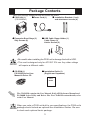
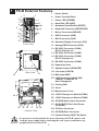
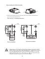
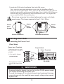
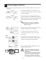
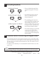
PS-2000B Series Installation Guide WARNINGS Follow the instructions given below to ensure the correct and safe use of the PS2000B Series unit, hereafter referred to as the “PS-B”. • To prevent an electrical shock, be sure to connect the power cord to the PS-B before connecting it to the main power supply. • A fire or electrical shock may result if voltages are used with the PS-B that are beyond the specified range. Be sure to only use the specified voltage. • Before opening the PS-B’s protective cover, be sure to turn the unit’s power OFF. This is because the PS-B’s internal parts carry high voltages. • If metal particles, water or other types of liquids contact any of the PS-B’s internal parts, immediately turn the unit’s power OFF, unplug the power cord, and contact your local PS-B distributor. • Read and understand Chapter 4 “Installation and Wiring” thoroughly in order to select an appropriate installation location for the PS-B. • Before either plugging in or unplugging an expansion board or interface connector, be sure to turn the PS-B’s power OFF. • To prevent a possible explosion, do not install the PS-B in areas containing flammable gases. • The PS-B is not appropriate for use with aircraft control devices, aerospace equipment, central trunk data transmission (communication) devices, nuclear power control devices, or medical life support equipment, due to these devices’ inherent requirements of extremely high levels of safety and reliability. • When using the PS-B with transportation vehicles (trains, cars and ships), disaster and crime prevention devices, various types of safety equipment, non-life support related medical devices, etc. redundant and/or failsafe system designs should be used to ensure the proper degree of reliability and safety. To Prevent Accidents Follow the instructions given below to ensure the correct and safe use of the PS-B. • If the screen becomes dirty or smudged, moisten a soft cloth with diluted neutral detergent, wring the cloth well, and wipe the display. Do not use thinner or organic solvents. • Avoid storing and operating the PS-B in direct sunlight, high temperatures and humidity, and in areas where excessive dust and vibration will occur. • Avoid using the PS-B in areas where sudden, extreme changes in temperature can occur. This may cause condensation to form inside the unit, possibly leading to an accident. • To prevent the PS-B from overheating, be sure its air circulation vents are clear and clean, and keep the unit’s operation area well-ventilated. • Avoid operating or storing the PS-B near chemicals, or where chemicals can come into contact with the unit. • The Digital Electronics Corporation cannot be held responsible or provide any compensation for damage(s) caused by the loss of data stored in the PS-B unit’s hard disk drive (HDD). It is therefore strongly suggested that all important data and software be backed up regularly to an external data backup device. • After turning OFF the PS-B's power, wait until the internal HDD stops spinning before turning the power ON again (approx. 5 seconds). 1 UL/c-UL (CSA) Application Notes The PS2000B-41 units are UL/c-UL 60950 recognized products. (UL File No. E171486). Please pay special attention to the following instructions when applying for UL/c-UL (CSA) approval for machinery which includes any of these PS-B units. The PS-B conforms as a component to the following standards: UL 60950, Third Edition (Standard for Safety of Information Technology Equipment, including Electrical Business Equipment) CSA-C22.2 No. 950-95 (Standard for Safety of Information Technology Equipment, including Electrical Business Equipment) PS2000B-41 (UL Registration Model No.: 3080005-01) - Equipment with a PS-B mounted in it requires UL/c-UL (CSA) evaluation for the combination of the PS-B and the equipment. - The PS-B must be used as a built-in component of an end-use product. - Use the PS-B indoors only. - When connecting the PS-B’s power cord, be sure to use a cord that is appropriate for the current and voltage used and that has conductive wires that are 0.75 mm2 or larger. - When using the PS-B in an end-use product, be sure to install the PS-B unit's power cut-off switch where the operator can easily reach it. - Danger of explosion if backup battery is incorrectly replaced. The PS-B unit’s battery should be replaced only with same or equivalent type recommended by the manufacturer. Dispose of used batteries according to the manufacturer’s instructions. - Be sure the unit the PS-B is built into uses a UL60950 compatible equipment structure. CE Marking Notes The PS2000B-41 units are CE marked, EMC compliant products. <Complies with the following Standards> • Safety EN60950 • EMI EN55011 (Group1 Class A), EN61000-3-2, EN61000-3-3 • EMS (EN61000-6-2) EN61000-4-2, EN61000-4-3, EN61000-4-4, EN61000-4-5, EN61000-4-6, EN61000-4-8, EN61000-4-11 If the following requirements are not met, the PS-B may fail to meet EN60950 standard requirements. • Equipment with a PS-B mounted in it requires UL/c-UL (CSA) evaluation for the combination of the PS-B and the equipment. • The PS-B must be used as a built-in component of an end-use product. • Use the PS-B indoors only. • When connecting the PS-B’s power cord, be sure to use a cord that is appropriate for the current and voltage used and that has conductive wires that are 0.75 mm2 or larger. • When using the PS-B in an end-use product, be sure to install the PS-B unit's power cut-off switch where the operator can easily reach it. • There is a danger of explosion if the backup battery is incorrectly replaced. The PS-B unit’s battery should be replaced only with the same or equivalent type recommended by the manufacturer. Dispose of used batteries according to the manufacturer’s instructions. • Be sure the PS-B unit's enclosure is an EN60950 approved sheet steel structure. 2 Package Contents The PS-B package should include the following items: PS-B Unit (1) (PS-2000B-41) Power Cord (1) Expansion Boad Stays (3) Stay Screws (6) Installation Brackets (1 set) and attachment screws (4) USB Cable Clamp Holder (1) Cable Clamp (2) Holder Screws (2) • Be careful when installing the PS-B not to damage the built-in HDD. • This cord is designed only for AC100/115V use. Any other voltage will require a different cable. CD-ROM (1) PS-2000B Series User Manual & Driver CD Installation Guide (1) (English and Japanese) This Guide The CD-ROM contains the User Manual, RAS-API Reference Manual and PS-2000B Series Utility and Driver files. For CD-ROM content details, refer to the User Manual. When you order a PS-B unit built to your specifications, the PS-B unit’s package should include an optional item Installation Guides. Be sure to check each optional item’s package. 3 About The Manual The PS-B unit’s CD-ROM contains the following PDF manual files. - PS-2000B Series User Manual - PS-2000B Series RAS-API Reference Manual Reading a PDF file requires installation of the Adobe Corporation’s Acrobat® Reader. Acrobat® Reader Installation: To install the Acrobat® Reader software, follow the steps given below. 1) This software, in the form of a self-extracting file, is located in this CD-ROM in the folder titled [reader]. Use the Explorer software to find the file [Reader\Eng\ar505enu.exe], and double-click on the file icon to begin the Reader installation. 2) After installation begins, follow the instructions given. Viewing the PDF manual: To view the PDF manual contained in this CD-ROM, follow the steps given below. 1) Use the Explorer software to locate the file [Manual\Eng\ps2000be.pdf or psbapie.pdf] in the folder titled [Manual]. 2) Double-click on the PDF file's icon. Acrobat® Reader will automatically start and the first page of the PDF manual will appear. 4 1 PS-B External Features 1 : Power Switch 4 5 3 2 2 : Power Terminal Block 3 : Power LED (POWER) 1 6 7 4 : Hard Disk LED (HDD) 21 8 20 19 9 10 17 11 5 : Hardware Reset Switch (RESET) 18 6 : Keyboard Connector (KEYBOARD) 7 : Mouse Connector (MOUSE) 16 12 13 14 15 8 : USB Connector (USB) 9 : RAS Connector (RAS) 10: Standard Display Connector (DVI) Front View 11 : Analog RGB Connector (VGA) 12: RS-232C Connector (COM1) RI/+5V Changeover 13: RS-232C Connector (COM2) 14: RS-232C Connector (COM3) RI/+5V Changeover 15: RS-232C Connector (COM4) 16: Expansion Slots 17: Speaker Output (SPEAKER) 18: Line Input (LINE IN) Side View 23 22 19: Mike Input (MIC) 20: LAN Connector (LAN1/LAN2) 10BASE-T/100BASE-TX Auto Changeover 21: Cooling FAN 22: Cover 23: Maintenance Cover 24: +5V/RI Changeover Switch (COM1) 30 25: +5V/RI Changeover Switch (COM3) 26: CD-ROM Sound Input Connector 24 25 26 27 27: CD-ROM/FDD Drive Unit Power Connector 28 29 28: FD Drive Connector Internal View 29: CD-ROM Drive Connector 30: Standard Display ON/OFF Dip Switch • To prevent an electrical shock, be sure to disconnect the PS-B’s power cord from the power supply before connecting the cord’s power terminals or any peripheral devices to the PS-B. 5 PS-B Dimensions (Unit: mm [in.]- excluding projections) Top View 39 [1.54] 118 [4.65] 260[10.24] 265 [10.43] 2 Front View Side View Dimensions including option units (CD-ROM/FD Drive Unit, RS-232C/RS-485 Conversion Unit), see “PS-2000B Series User Manual” 6 3 General Specifications Electrical Rated Voltage Allowable Voltage Range Rated Frequency AC 100V/AC 240V AC 85V to AC 265V 50/60Hz 1 cycle or less Allowable Voltage Drop (however, pause occurrences must be more than 1 second apart) Power Consumption 110VA or less AC 1500V at 20mA for 1 minute Voltage Endurance (between charging and FG terminals) 10M Ω or higher at DC 500V Insulation Resistance (between charging and FG terminals) Environmental Ambient Operating Temperature (Cabinet Interior) Storage Temperature Ambient Humidity Air Purity Level Pollution Degree Atmosphere o o o o 5 C to 50 C (With HDD attached) 0 C to 50 C (Without HDD) o o -10 C to 60 C 10% RH to 85% RH o (Non condensing, wet blub temperature : 29 C) Free of dust Pollution Degree 2 Free of corrosive gas 2 Vibration Resistance Noise Endurance (Impulse Noise) Electrostatic Discharge Immunity Noise Immunity (First transient burst noise) 9.8m/s at 10Hz to 25Hz in X, Y, Z directions for 30 minutes With HDD attached : 4.9m/s 2 Noise Voltage: 1500V Pulse Duration: 50ns, 500ns, 1µs Rise Time : 1ns (via noise simulator) 6kV IEC 61000-4-2 Power Line : 2kV IEC 61000-4-4 COM Port : 1kV IEC6100-4-4 7 Structural Grounding Installation Method Cooling Method Weight External Dimensions Dimensions Including CD-ROM/FD Drive Unit Dimensions Including RS-232C/RS-485 Conversion Unit Exclusive grounding only. Less than 100Ω , or your country’s applicable standard. Inside a solid via main unit fan or CPU fan Less than 4.5 kg (9.9 lb) (excluding projections) W118 mm [4.65 in.] x H265 mm [10.43 in.] x D299 mm [11.77 in.] (excluding projections) W159 mm [6.26 in.] x H265 mm [10.43 in.] x D299mm [11.77 in.] (excluding projections) W139.5 mm [5.49 in.] x H265 mm [10.43 in.] x D299 mm [11.77 in.] (excluding projections and cable) 8 4 Interface Specifications RS-232C Interface (COM1/COM2/COM3/COM4) Dsub 9 pin (Male) 1 2 6 3 7 4 8 Pin No. 5 1 2 3 4 5 9 Screw Size: (4-40): Inch Type Signal Name CD RXD TXD DT R GND Pin No. 6 7 8 9 Signal Name DSR RT S CT S RI/+5V • The GND terminal is the signal ground. Be sure to connect the PL unit’s GND terminal to the other unit’s SG (signal ground). • FG and SG terminals are internally connected in the PS-B. When connecting to another device, be sure to create an SG shorting loop in your system. Changing number 9 pin’s [+5V/RI] can only be done for COM1, or COM3. With COM2 and COM4, only [RI] is available. To change the COM1 or COM3 [+5V/RI] setting, remove the PS-B unit’s cover and locate the changeover switch on the side of the main circuit board. The factory setting is to [RI]. PS-2000B Series User Manual 1.4.1 RS-232C Interface • Be sure to confirm what settings will be used by the other device and set the dip switches accordingly. Failure to do so can result in a unit malfunction or damage. • Whenever changing the PS-B changeover switches, be sure to first turn the PS-B’s power supply OFF. Failure to do so can cause a PS-B malfunction. 9 RAS Interface Pin No. Signal Name Pin No. Signal Name 1 GND 14 GND 2 +5V (MAX. 100mA) 15 +5V 3 +12V (MAX. 100mA) 16 DIN3 (+) 4 NC 17 DIN3 (-) 5 DIN2 (+) 18 RST (+) 6 DIN 0 (+) 19 DOUT1 (-) 7 DOUT2 (-) 20 DOUT1 (+) 8 DOUT2 (+) 21 DOUT3 (-) 9 DOUT0 (-) 22 DOUT3 (+) 10 DOUT0 (+) 23 RST (-) 11 DIN2 (-) 24 DIN1 (-) 12 DIN 0 (-) 25 NC 13 DIN 1 (+) Dsub 25 pin (Male) 1 2 3 4 5 6 7 8 9 10 11 12 13 14 15 16 17 18 19 20 21 22 23 24 25 Screw Size: (4-40): Inch Type When using No.2 (+5V) and No.3 (+12V) External Power Output, be sure to use only the designated level of current. Not doing so could couse a damage or a unit malfunction. External Input Signal (Dual use of DIN, RST Input Port) Input Voltage Input Current Operating Voltage Isolation Method DC12V to DC24V 7mA ON voltage: 9V (min), OFF voltage:3V (max) Via photocoupler (Interface Circuit) (Connection Example) +5V 1.8kΩ 1/10W R No polarity - for Sink/ Source input 1.8kΩ 1/10W DIN0(+), DIN1(+) DIN2(+), DIN3(+) RST(+) Cable R DC12V to DC24V DIN0(-), DIN1(-) DIN2(-), DIN3(-) RST(-) PC357 D-sub 25 pin Connector switch or switching device • General Purpose Input (DIN)’s input level must be 1.5 seconds or longer to be detected. • Be sure the voltage value between terminals is controlled via the input voltage, so that the PS-B is operated within its recommended range. If the input voltage exceeds this range, a malfunction or PS-B damage may occur. • With Sink/Source input, even if DIN(-), and RST(-) are positive, and DIN(+), RST(+) are negative, no problems are created. Be sure to operate the unit within the recommended voltage range. 10 External Output Signal (DOUT Port) Rated Load Voltage DC12V to DC24V 100mA/point Maximum Load Current Maximum Voltage Drop between Terminals 1.5V (at 100mA load current) Isolation Method Via photocoupler (Interface Circuit) (Connection Example) +5V DOUT0(+), DOUT1(+) DOUT2(+), DOUT3(+) R Load *1 Cable SSTA06 PC357 DC12 to DC24V 4.7kΩ DOUT0(-), DOUT1(-) DOUT2(-), DOUT3(-) D-sub 25 pin Connector Be sure to operate the unit within its maximum load current. If the maximum load current exceeds this range, a malfunction or PS-B damage may occur. 5 Installing the PS-B Use the following procedures to install the PS-B into a solid panel. 1) Use the four (4) attachment screws included in the PS-B’s packing box to attach the mounting brackets to the PS-B main unit. Be careful that each bracket is attached to the correct side. When Installing the PS-B vertically 11 When Installing the PS-B horizontally 2) Drill the attachment holes in the panel. Be sure to follow the dimensions given for the attachment holes. (Unit : mm [in.] - excluding projections) 137+0.5 [5.39+0.02] (55[2.17]) (118[4.65]) 170+0.5 [6.69+0.02] 4-M4 260[10.24] 170+0.5 [6.69+0.02] (55[2.17]) 260[10.24] 4-M4 (265[10.43]) 284+0.5[11.18+0.02] (302[11.89]) (155[6.10]) Horizontal Installation Vertical Installation • Depending on the panel’s material and design, the panel’s installation surface may need to be strengthened. If high levels of vibration are expected and the PS-B’s installation surface (i.e. an operation panel’s door, etc.) can move (i.e. open or close) due consideration should be given to the PS-B’s weight. 12 3) Attach the PS-B to the Installation Panel with M4 screws. First, insert the main unit attachment screws into the Installation Panel’s holes, but do not tighten them. Then, place the PS-B main unit on the panel so that the bracket holes and the screw heads align. Next, slide the PS-B down so that the main unit is supported by these attachment screws. Last, tighten the screws until the PS-B is secured in place. Do not use excessive force when tightening the main unit attachment screws. The torque required is from 1.0 to 1.2N•m. Attachment Screws Attachment Screws Attachment Screws Horizontal Installation Vertical Installation 6 Wiring the PS-B Connecting the Power Cord (Front View) Power Input Terminals Power Switch Connecting these two terminals provides AC100V/ AC240V. L= Live and N= Neutral (screw size: M3) Power Terminals L N FG PS-2000B This terminal is connected to the PS-B’s frame (chassis). WARNINGS • To prevent electric shocks, be sure to turn the PS-B's power supply OFF before connecting the power cord. • To avoid the dangers of fire, electric hazards and equipment damage, be sure to use only the specified power supply voltage when operating the PS-B. 13 Use the following steps when connecting the power cord to the PS-B’s power terminals. 1) Confirm that the PS-B unit’s power supply is turned OFF. 2) Use a screwdriver to remove the Power Input Terminal Block’s clear plastic cover. 3) Unscrew the screws from the middle three(3) terminals, align the Ring Terminals*1 and reattach the screws. φ 3.2 mm or larger Black L Max. 6.0 mm N FG White Green/ Yellow • Confirm that the wires are connected correctly. • The torque required to tighten these screws is 0.5N•m. • To prevent the possibility of a Ring Terminal short, use a Ring Terminal that has an insulating sleeve. 4) Replace the Power Input Terminal Block’s clear plastic cover. *1 Suggested Ring Terminal : RAV1.25-3 <made by JST> 14 7 Power Supply Cautions When connecting the PS-B unit’s AC power terminals, please be aware of the following: Constant voltage transformer Insulating transformer Twisted-pair cord PS-B FG Twisted-pair cord PS-B FG • If voltage fluctuations are expected to vary beyond the specified range, connect a constant voltage transformer. • Use a low-noise power supply both between the lines and between the PS-B and its ground. If there is still excess noise, connect an insulating transformer (noise-prevention type) . Be sure any constant or insulating transformer used has a capacity of 200VA or more. AC100V PS-B PS-B power source Main power source I/O power source I/O device Main power source AC 200V PS-B PS-B power T1 source T2 • Wire the power cords of the PS-B, I/O devices, and power supply devices separately. • To improve noise immunity, Pro-face is recommends attaching a ferrite core to the power cord. • Isolate the main circuit (high voltage, large current) line, I/O signal lines, and power cord, and do not bind or group them together. I/O device I/O power source I/O device Power device Main circuit power source • To prevent damage from lightning, connect a lightning surge absorber. • Ground the lightning surge absorber (E1) and the PS-B (E2) separately. • Select a lightning surge absorber which will not exceed the allowable circuit voltage, even when the voltage rises to the maximum. PS-B AC FG Twisted-pair cable E2 E1 Lightning surge absorber 15 8 Grouding Cautions (a) Dedicated Ground PS-B • Set up a dedicated ground when using the front panel’s FG terminal. Other device • If a dedicated ground is not possible, use a shared ground, as shown in figure (b). (b) Shared Ground - allowed PS-B Other device (c) Shared ground - not allowed PS-B Other device • The grounding point must be as close to the PS-B as possible, and the grounding wires must be as short as possible. If the wires must be long, use thick, insulated wires and run them through conduits. • FG and SG terminals are internally connected in the PS-B. When connecting to another device, be sure to create an SG shorting loop in your system. 9 Cautions When Connecting I/O Signal Lines • I/O signal lines must be wired separately from the power circuit cable. If the power cord needs to be wired together with the input/output (I/O) signal lines for any reason, use shielded cord and ground one end of the shield to the PSB’s FG terminal. • To improve noise immunity, it is recommended to attach a ferrite core to the power cord. Note Be aware that the Digital Electronics Corporation shall not be held liable for any real or estimated damages or losses, or third party claims resulting from the use of this product. © 2002 Digital Electronics Corporation. All rights reserved. 057470H .PS2000B-MT01-BTHE 16 2002.10. JM/A