1
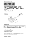
Owner's Manual
BN°
TI ETLL
UAL OTATI
iT
TI ES
900 Series
17 Inch Tine Width
Model No.
917.299081
• EspaSol,
p. 23
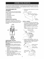
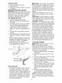
This product has a low emission
engine which operates
differently
from previously built engines. Before you start the
engine, read and understand
this Owner's Manual.
IMPORTANT:
Read and follow all Safety
Rules and Instructions before
operating
this equipment.
Sears, Roebuck
Visit our Craftsman
and Co., Hoffman
website:www.sears.com/craftsman
428422 Rev. 1
Estates,
IL 60179
U.S.A.
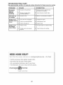
Warranty ................................................
Safety Rules ..........................................
Product Specifications
.........................
Assembly/Pre-Operation
.......................
Operation ...............................................
Maintenance
Schedule ........................
LIMITED TWO YEAR WARRANTY
Maintenance
2
2
4
6
8
14
.......................................
14
Service and Adjustments
.....................
16
Storage ................................................
20
Troubleshooting
...................................
21
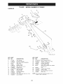
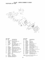
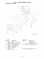
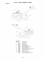
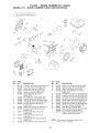
Illustrated
Parts List .............................
44
Sears Service ........................
Back Cover
ON CRAFTSMAN
TILLER
For two (2) years from date of purchase,
when this Craftsman
Tiller is maintained,
lubricated,
and tuned up according
to the operating
and maintenance
instructions
in the
owner's manual, Sears will repair free of charge any defect in material or workmanship.
This Warranty
• Expendable
air cleaners
does not cover:
items which become
and belts.
worn during
normal
use, such as tines,
spark
plugs,
• Repairs necessary
because of operator abuse or negligence,
including bent crankshafts and the failure to maintain the equipment
according
to the instructions
contained in the owner's manual.
• If this Craftsman
Tiller is used for commercial
or rental
plies for only thirty (30) days from the date of purchase.
purposes,
this Warranty
ap-
Warranty
service is available by returning the craftsman
power mower to the nearest
sears service center/department
in the united states. This warranty applies only while
this product is in use in the united states.
This Warranty
gives you specific
vary from state to state.
SEARS,
ROEBUCKAND
legal rights,
CO., D/817WA,
and you may also have other
HOFFMAN
ESTATES,
IL 60179
rights
which
U.S.A.
IMPORTANT:
This cutting machine is capable of amputating
hands and feet and throwing objects. Failure to observe the following
safety instructions
could result in serious
injury or death.
TRAINING
• Disengage
all clutches and shift into
neutral before starting the engine (motor).
• Do not operate the equipment
without
wearing adequate
outer garments.
Wear
footwear that will improve footing on
slippery surfaces.
• Handle fuel with care; it is highly flammable.
• Read the Owner's Manual carefully.
Be
thoroughly
familiar with the controls and
the proper use of the equipment.
Know
how to stop the unit and disengage
the
controls quickly.
• Never allow children to operate the
equipment.
Never allow adults to operate the equipment
without proper
instruction.
• Keep the area of operation
persons, particularly
small
pets.
• Use an approved fuel container.
• Never add fuel to a running engine
hot engine.
• Fill fue! tank outdoors with extreme
care. Never fill fuel tank indoors.
clear of all
children,
and
PREPARATION
•
• Thoroughly
inspect the area where the
equipment
is to be used and remove all
foreign objects.
2
or
Replace gasoline cap securely and
clean up spilled fuel before restarting.
• Use extension
cords and receptacles
as specified
by the manufacturer
for all
units with electric drive motors or elec-
• Never operate the machine at high
speeds on slippery surfaces.
Look behind and use care when backing.
• Never allow bystanders
near the unit.
• Use only attachments
and accessories
approved
by the manufacturer
of the
tiller.
tric starting motors.
• Never attempt to make any adjustments
while the engine (motor) is running (except where specifically
recommended
by manufacturer).
• Never operate the tiller without good
visibility or light.
• Be careful when tilling in hard ground.
The tines may catch in the ground and
propel the tiller forward.
If this occurs,
let go of the handlebars
and do not
restrain the machine.
OPERATION
• Do not put hands or feet near or under
rotating parts.
• Exercise extreme caution when operating on or crossing gravel drives, walks,
or roads. Stay alert for hidden hazards
or traffic. Do not carry passengers.
• After striking a foreign object, stop the
engine (motor), remove the wire from
the spark plug, thoroughly
inspect the
tiller for any damage,
and repair the
damage before restarting
and operating
the tiller.
• Exercise caution
ing.
• If the unit should
to avoid
slipping
start to vibrate
MAINTENANCE
AND STORAGE
• Keep machine,
attachments,
and accessories in safe working condition.
• Check shear pins, engine mounting
bolts, and other bolts at frequent
intervals for proper tightness
to be sure the
equipment
is in safe working condition.
• Never store the machine with fuel in the
or fall-
fuel tank inside a building where ignition
sources are present, such as hot water
and space heaters, clothes dryers, and
the like. Allow the engine to cool before
storing in any enclosure.
• Always refer to the operator's
guide instructions for important
details if the tiller
is to be stored for an extended
period.
_Look
for this symbol to point out
ab-
normally, stop the engine (motor) and
check immediately
for the cause. Vibration is generally
a warning of trouble.
• Stop the engine (motor) when leaving
the operating
position.
• Take all possible precautions
when
leaving the machine
unattended.
Disengage the tines, shift into neutral, and
stop the engine.
• Before cleaning,
repairing, or inspecting,
shut off the engine and make certain all
moving parts have stopped. Disconnect
the spark plug wire, and keep the wire
away from the plug to prevent accidental starting. Disconnect
the cord on
electric motors.
important safety precautions.
It means
CAUTION!!!
BECOME
ALERT!!!
YOUR
SAFETY IS INVOLVED.
,JI_CAUTION:
Always
disconnect
spark
plug wire and place wire where it cannot
contact spark plug in order to prevent accidental starting when setting up, transporting, adjusting
or making repairs.
• LWARNING:
Engine exhaust, some of its
constituents,
and certain vehicle components contain or emit chemicals
known to
the State of California
to cause cancer and
• Do not run the engine indoors; exhaust
fumes are dangerous.
• Never operate the tiller without proper
guards, plates, or other safety protective
devices in place.
• Keep children and pets away.
• Do not overload the machine capacity
by attempting
to till too deep at too fast
a rate.
birth defects
3
or other
reproductive
harm.
PRODUCT
Gasoline
SPECIFICATIONS
Capacity:
In the state of California
SAE 30 (Above 32°F)
SAE 5W-30 (Below 32°F)
Spark Plug:
(Gap: .030"/0.76mm)
NGK-BPR6ES
TOROH-F6RTC
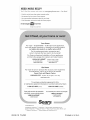
REPAIR PROTECTION
AGREEMENTS
Congratulations
on making a smart purchase. Your new Craftsman@ product is
designed and manufactured
for years of
dependable
operation. But like all products,
it may require repair from time to time. That's
when having a Repair Protection Agreement
can save you money and aggravation.
Purchase
a Repair Protection
Agreement
now and protect yourseff from unexpected
hassle and expense.
Here's what's included in the Agreement:
•
Expert service by our 12,000 profesional repair specialists.
•
Unlimited
service and no charge for
parts and labor on all covered repairs.
•
Product replacement
if your covered
product can't be fixed.
•
Discount of 10% from regular price of
service and service-related
parts not
covered by the agreement;
also, 10%
off regular price of preventive
maintenance check.
•
Fast help by phonephone support
from a Sears technician
on products
requiring in-home repair, plus convenient repair scheduling.
Once you purchase
the Agreement,
a
simple phone call is all that it takes for you
to schedule
service. You can call anytime
day or night, or schedule
a service appointment
online.
Sears has over 12,000 professional
repair
specialists,
who have access to over 4.5
million quality parts and accessories.
That's the kind of professionalism
you can
count on to help prolong the life of your
new purchase
for years to come. Purchase your Repair Protection
Agreement
today!
Some limitations
and exclusions
apply.
For prices and additional
information
call 1-800=827=6655.
CONGRATULATIONS
on your purchase
of a Sears Tiller. It has been designed,
engineered
and manufactured
to give you
the best possible dependability
and performance.
Should you experience
any problems you
cannot easily remedy, please contact a
Sears or other qualified Service Center.
We have competent,
well-trained
technicians and the proper tools to service or
repair this unit.
Please read and retain this manual. The
instructions
will enable you to assemble
and maintain your tiller properly. Always
observe the "SAFETY
RULES".
Your new tiller has been assembled
at the
factory with exception
of those parts left
unassembled
for shipping purposes.
To
ensure safe and proper operation
of your
tiller all parts and hardware
you assemble
must be tightened
securely. Use the correct tools as necessary
to insure proper
tightness.
CUSTOMER
RESPONSIBILITIES
• Read and observe the safety
• Follow a regular schedule
in
ing, caring for and using your
• Follow the instructions
under
is
required
by law (Section 4442 of the
California
Public Resources
Code).
Other
states may have similar laws. Federal
laws apply on federal lands. A spark atrester for the muffler is available through
your nearest Sears service center
(See
REPAIR PARTS section of this manual).
3 Quarts (2.8L)
Unleaded Regular
Oil (API-SG-SL):
(Capacity:20oz./0.6L)
the above
rules.
maintaintiller.
the "Main-
tenance"
and "Storage" sections of this
_Owner's
Manual.
WARNING:
This unit is equipped
with
an internal combustion
engine and should
not be used on or near any unimproved
forest-covered,
brush-covered
or grass
covered land unless the engine's
exhaust
system is equipped with a spark arrester
meeting applicable
local or state laws (if
any). If a spark arrester is used, it should
be maintained
in effective working order
by the operator.
SEARS
INSTALLATION
SERVICE
For Sears professional
installation
of
home appliances,
garage door openers,
water heaters, and other major home
items, in the U.S.A. call 1-800-4-MYHOME@
4
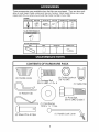
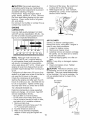
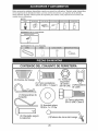
These accessories
able at most Sears
repair
were available when the tiller was purchased.
They are also availRetail outlets and Service Centers.
Most Sears Stores can order
parts for you when
you provide
the model
number
of your tiller.
ENGINE
SPARK
TILLER
PLUG
MUFFLER
AiR FILTER
GAS CAN
ENGINE OiL
STABiLiZER
PERFORMANCE
FURROW
OPENER
¢
TILLER
MAINTENANCE
BELT
TINES
SHEAR
PiN
HAiRPiN
CLIP
O
CONTENTS OF HARDWARE PACK
Q
(2) Handle Locks
(1) Carriage Bolt
3/8-16 UNC x 1 Gr. 5
(1) Center Locknut
3/8-16 UNC
(1) Cable Clip
D
(1) Hairpin Clip
(1) Pivot Bolt
3/8-16 UNC Grade 5
(1) Flat Washer
13/32xlx11Ga,
©
(1) Handle Lock Lever
(2) Shear Pins & Clips
5
Your new tiller has been assembled
at the factory with the exception
of those parts left
unassembled
for shipping purposes.
To ensure safe and proper operation
of your tiller
all parts and hardware you assemble
must be tightened
securely.
Use the correct tools
as necessary
to insure proper tightness.
TOOLS REQUIRED
ASSEMBLY
A socket wrench
easier. Standard
(1)
(1)
(1)
(1)
(1)
(1)
Utility knife
Wire cutter
Tire pressure
Screwdriver
Pair of pliers
9/16" wrench
OPERATOR'S
FOR
.
Remove packing material from handle
assembly.
set will make assembly
wrench sizes are listed.
Shift Rod
gauge
Handle
Assembly
POSITION
When right or left hand is mentioned
in
this manual, it means when you are in the
operating
position (standing behind tiller
handles).
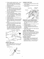
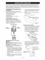
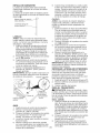
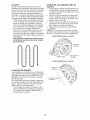
INSTALL
.
FRONT
LEFT
Insert one handle lock (with teeth facing outward)
in gearcase
notch. (Apply
grease on smooth side of handle lock
to aid in keeping lock in place until
handle assembly
is lowered into position.)
VIEWED FROM R.H. SIDE OF TILLER
_.
RIGHT
HANDLE
Handle Assembly
Gearcase Notch
/
OPERATOR'S
POSITION
UNPACKING
2.
4.
handle
assembly.
Hold
in "up"
position. Be sure handle lock remains
in gearcase notch. Slide handle assembly into position.
CARTON
_ILCAUTION:
Be careful of exposed
staples when handling or disposing
of cartoning material.
IMPORTANT:
When unpacking
and assembling tiller, be careful not to stretch or
kink cables.
1. While holding handle assembly, cut
cable ties securing handle assembly
to
top frame.
Let handle assembly
rest
on tiller.
2.
3.
Grasp
H/andle Lock
"_')!'_:
Loosen Handle
Lock Lever to
Move
Remove top frame of carton.
Slowly ease handle assembly
up and
place on top of carton.
Cut down right hand front and right
hand rear corners of carton.
Lay side
carton wall down.
6
'
Handle Assembly
Position
3.
Rotate handle assembly
down.
Insert
rear carriage bolt first, with head of
bolt on LH. side of tiller and loosely
assemble
Iocknut.
4.
Insert pivot bolt in front part of plate
and tighten.
Cut down left hand rear corner of car-
5.
6.
7.
8.
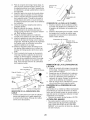
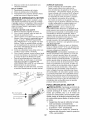
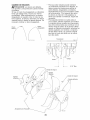
CONNECT SHIFT ROD
1. Insert end of shift rod into hole of shift
lever indicator.
2. Insert hairpin clip through hole of shift
rod to secure.
Hairpin Clip
ton. Lay rear carton wall down, which
will remove the protective
cardboard
flap from leveling shield.
Cut down remaining
corners of carton
and lay panels flat.
Lower the handle assembly.
Tighten
nut on carriage bolt so handle moves
with some resistance.
This will allow
for easier adjustment.
Place flat washer on threaded
handle lock lever.
Shift Lever
Indicator
Shift Rod
end of
9.
Insert handle lock lever through handle
base and gearcase.
Screw in handle
lock lever just enough to hold lever in
place.
10. Insert second handle lock (with teeth
inward) in the slot of the handle base
(just inside of washer).
11 .With handle assembly
in lowest position, securely tighten handle lock lever
by rotating clockwise.
Leaving handle
assembly
in lowest position will make it
easier to remove tiller from carton.
Flat Washer
Handle Lock
REMOVE
1. Adjust handle assemby to lowest position. Be sure lock lever is tightened
securely.
2. Make sure shift lever indicator is in "N"
3.
4.
Handle Lock
Lever
(neutral) position.
Tilt tiller forward by lifting handle.
Separate cardboard
cover from leveling shield.
Rotate tiller handle to the right and pull
tiller out of carton.
CHECK
Rear
Slot
HANDLE
_(_
Pivot Bolt
Adjustments
Handle Base
CABLE
CLiP
• Insert plastic cable clip into hole on the
back of handle column.
Push cables
into clip.
Handle Column
\
Cable Clip
handles
HEIGHT
Handle height may be adjusted to better suit operator.
(See "TO ADJUST
HANDLE
HEIGHT"
in the Service and
Locknut j
INSERT
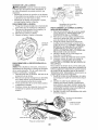
TIRE PRESSURE
The tires on your unit were overinflated
at
the factory for shipping purposes.
Correct
and equal tire pressure
is important for
best tilling performance.
• Reduce tire pressure to 20 PSI.
\
Cartridge
Bolt
TILLER FROM CRATE
14
7
section
of this manual).
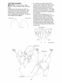
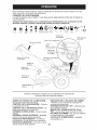
These symbols
may appear on your Tiller
Learn and understand
their meaning.
or in literature
supplied
with the product.
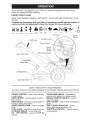
KNOW YOUR TILLER
READ THIS OWNER'S MANUAL AND SAFETY RULES BEFORE OPERATING YOUR
TILLER.
Compare the illustrations with your tiller to familiarize yourself with the location of
various controls and adjustments.
Save this manual for future reference.
."
t\t
CAUTION
TILLING
TILLING
FORWARD
NEUTRAL
REVERSE
ENGINE
OR WARNING
ENGINE
ON
FAST
SLOW
CHOKE
SToPO
I
FUEL
OIL
OFF
Fuel Valve
Shift Lever
On/Off
Switch
Throttle
Choke
Recoil
Starter
Handle
Drive Control Bar
Shift Lever Indicator
Drag
Depth Stake
Leveling Shield
Outer Side Shield
MEETS ANSI SAFETY
Our tillers conform to the safety standards
CHOKE CONTROL
- Used when starting
a cold engine
DEPTH STAKE - Controls depth at which
tiller will dig.
DRAG STAKE - Controls forward speed in
forward rotating till position.
DRIVE CONTROL
BAR - Used to engage
tines.
FUEL VALVE = Used to turn fuel off and on.
LEVELING
SHIELD - Levels tilled soil.
ON / OFF SWITCH
- used to STOP the
engine.
REQUIREMENTS
of the American
National Standards
Institute.
OUTER SIDE SHIELD - Adjustable
to
protect small plants from being buried.
RECOIL STARTER
HANDLE
- Used to
start the engine.
SHIFT LEVER - Used to shift transmission
gears.
SHIFT
LEVER
INDICATOR
- Shows
which gear the transmission
is in.
THROTTLE
CONTROL
- Used to control
engine
8
speed.
The operation
of any tiller can result in foreign objects
which can result in severe eye damage.
Always wear
shields before starting your tiller and while tilling. We
safety glasses or a wide vision safety mask worn over
HOW TO USE YOUR TILLER
Know how to operate all controls
adding fuel and oil or attempting
engine.
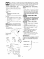
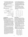
TINE OPERATION
DRIVE
before
to start
TINES
Release drive control
movement.
bar to stop
2. Move shift lever to "N" (neutral)
ENGINE
position.
FORWARD
STOPPED
2. Move throttle control to "SLOW" position and allow the engine to run slowly
for cool down.
3. Turn the engine switch to the "OFF"
Position.
4. Turn the fuel valve lever to the "OFF"
Position.
NOTE: Never use choke to stop engine.
IMPORTANT: To stop engine in an emergency, turn the engine switch to the OFF
position.
Drive Control Bar
"ENGAGED"
- WITH WHEEL
• Always release drive control bar before
moving shift lever into another position.
• Tine movement
is achieved
by moving
shift lever to either the counter rotating
(_) till position or the forward rotating
(_) till position and engaging
drive control bar.
STOPPING
1.
thrown into the eyes,
safety glasses or eye
recommend
standard
spectacles.
- WHEELS
ONLY/TINES
• Release drive control bar and move shift
lever indicator to "F" (forward) position.
Engage drive control bar and tiller will
move forward.
REVERSE - WHEELS ONLY/TINES
STOPPED
1.
DO NOT STAND DIRECTLY
BEHIND
TILLER.
2. Release the drive control bar.
3. Move throttle control to "SLOW" position.
4. Move shift lever indicator to "R" (reverse) position.
5. Hold drive control bar against the
handle to start tiller movement.
HARD TO SHIFT GEARS
Shift Lever
• Briefly engage drive control bar and
release or rock tiller forward and backward until are able to shift gears.
Drive Control Bar
"DISENGAGED"
Position
DEPTH STAKE
Throttle
Control
Engine
Switch
The depth stake can be raised or lowered
to allow you more versatile tilling and cultivating, or to more easily transport your
tiller.
Fuel
Valve
Shallowest Tilling -..._.
-" Transport Position
Deepest Tilling
Depth Stake
Engine
Switch
9
DRAG
STAKE
.
5.
The drag stake should be raised when
tilling the counter rotating (_) till position.
The drag stake should be lowered when
tilling in the forward rotating (_) till position.
.
Lift handle to raise tines out of ground.
Swing the handle in the opposite direction you wish to turn, being careful to
keep feet and legs away from tines.
When you have completed
your turnaround, release the drive control bar
and lower handle.
Place shift lever in
(till) position and move throttle control
to desired speed.
To begin tilling, hold
drive control bar against the handle.
Lowered ----"-(Forward Rotating till)
CULTIVATING
Raised
(Counter rotating till)
NOTE: Use the forward rotating tine drive
when cultivating,
tilling soft ground or tilling pre-tilled soil.
1. Release the depth and drag stake
pins. Lower drag stake. Pull the depth
stake up for increased
tilling depth.
Place proper pin in hole of depth stake
or drag stake to lock in position.
2. Place shift lever indicator
in forward
TILLING
NOTE: Use the counter rotating tine drive
when tilling hard or rockey soil, virgin
ground or sod.
1. Release depth stake and drag stake
pins. Pull the depth stake up for
increased tilling depth.
Raise the drag
stake. Place proper pin in hole of depth
stake or drag stake to lock in position.
2. Place shift lever indicator in counter
3.
3.
rotating (_) till position.
Hold the drive control bar against the
handle to start tilling movement.
Tines
and wheels will both turn.
4.
Move throttle control "FAST" position
for deep tilling. To cultivate, throttle
control can be set at any desired
speed, depending
on how fast or slow
you wish to cultivate.
OUTER
SIDE SHIELDS
rotating
(_,) till position.
Hold the drive control bar against the
handle to start tilling movement.
Tines
and wheels will both turn.
The back edges of the outer side shields
are slotted so that the shields can be
4.
Move throttle control to "FAST" position
for deep tilling.
IMPORTANT:
Always release drive control
bar before moving shift lever into another
position.
"Locked" Position
raised for deep tilling and lowered for
shallow tilling to protect small plants from
being buried.
1. Loosen nut '_' in slot and nut "B".
2.
3.
\
Move shield to desired
sides).
Retighten
nuts.
position
(both
TO TRANSPORT
_CAUTION:
Before lifting or transporting,
allow tiller engine and muffler to cool. Disconnect spark plug wire. Drain gasoline
from fuel tank.
AROUND
THE YARD
Depth or Drag
Pin
1.
Position
Nut
Outer Side
Shield
TURNING
2.
1.
Release
the drive control
2.
Move throttle
tion.
3.
Place shift lever indicator in "F" (forward) position.
Tines will not turn.
control
bar.
to "SLOW"
3.
posi-
4.
10
Release the depth stake pin. Move
the depth stake down to the top hole
for transporting
the tiller. Place depth
stake pin in hole of depth stake to lock
in position.
This prevents tines from
scuffing the ground.
Place shift lever indicator
in "F" (forward) position for transporting.
Hold the drive control bar against the
handle to start tiller movement.
Tines
will not turn.
Move throttle control to desired speed.
AROUND
TOWN
1.
2.
Disconnect
spark
Drain fuel tank.
3.
Transport in upright
oil leakage.
BEFORE
AI_,CAUTION:
Fill to within 1/2 inch of top
of fuel tank to prevent spills and to allow
for fuel expansion.
If gasoline is accidentally spilled, move machine away from
area of spill. Avoid creating any source of
ignition until gasoline vapors have disappeared.
Wipe off any spilled oil or fuel. Do not
store, spill or use gasoline near an open
flame.
plug wire.
position
STARTING
to prevent
ENGINE
IMPORTANT:
Be very careful not to allow
dirt to enter the engine when checking or
adding oil or fuel. Use clean oil and fuel
and store in approved,
clean, covered
containers,
use clean fill funnels.
FILL ENGINE WITH OIL
1.
2.
3.
4.
IMPORTANT:
When operating
in temperatures below32°F(0°C),
use fresh, clean
winter grade gasoline to help insure good
cold weather starting.
CAUTION:
Alcohol blended fuels (called
gasohol or using ethanol or methanol)
can
attract moisture which leads to separation
and formation
of acids during storage.
Acidic gas can damage the fuel system
of an engine while in storage.
To avoid
engine problems,
the fuel system should
be emptied before storage of 30 days
or longer. Drain the gas tank, start the
engine and let it run until the fuel lines
and carburetor
are empty.
Use fresh fuel
next season.
See Storage Instructions
for
additional
information.
Never use engine
or carburetor
cleaner products in the fuel
tank or permanent
damage may occur.
Remove hangtag from engine.
With engine level, remove engine oil
filler plug.
Fill engine with oil to point of overflowing. For approximate
capacity see
"PRODUCT
SPECIFICATIONS"
on
page 4 of this manual. All oil must
meet A.RI. Service
Classification
SGSL.
Tilt tiller back on its wheels and then
re-level.
5.
With engine level, refill to point of overflowing if necessary.
Replace oil filler
plug.
• For cold weather operation
you should
change oil for easier starting (See "OIL
VISCOSITY
CHART" in the Maintenance section of this manual).
• To change engine oil, see the Maintenance section of this manual.
TO START ENGINE
,ACAUTION:
Keep tine control in "OFF"
position when starting engine.
When starting engine for the first time or
if engine has run out of fuel, it will take
extra pulls of the recoil starter to move fuel
from the tank to the engine.
1. Make sure spark plug wire is properly
connected.
2.
3.
Min Lower Level }_
ADD GASOLINE
of filler neck.
the fuel valve
to the "ON"
posi-
To start a cold engine, move the choke
lever to the "ON" position.
4. Move the throttle lever away from the
"SLOW" position, about 1/3 of the way
toward the "FAST" position.
5. Turn the engine switch to the "ON" position. Pull rope out slowly until engine
reaches start of compression
cycle
(rope will pull slightly harder at this
point).
6. Pull recoil starter handle quickly.
Do not let starter handle snap back
against starter.
Repeat if necessary.
NOTE: If engine fires but does not start,
move choke control to half choke position. Pull recoil starter handle until engine
starts.
Max Upper Level
Fill fuel tank to bottom
Place
tion.
Do
not overfill.
Use fresh, clean, regular
unleaded
gasoline with a minimum
of
87 octane.
(Use of leaded gasoline will
increase carbon and lead oxide deposits and reduce valve life). Do not mix oil
with gasoline.
Purchase
fuel in quantities that can be used within 30 days to
assure fuel freshness.
11
7.
If the choke
lever has been
moved
to
• You will find tilling much easier if you
leave a row untilled between passes.
Then go back between tilled rows.There
are two reasons for doing this. First,
wide turns are much easier to negotiate than about-faces.
Second, the tiller
won't be pulling
itself, and you, toward
the row next to it.
• Do not lean on handle.
This takes
the "ON" position to start the engine,
gradually
move it to the opposite position as the engine warms up.
NOTE:
A warm engine requires less
choking to start.
8. Move throttle control to desired running
position.
9. Allow engine to warm up for a few
minutes before engaging
tines.
NOTE:
If engine does
troubleshooting
points.
weight off the wheels and reduces
traction.
To get through a really tough
section of sod or hard ground, apply
upward pressure
on handle or lower the
depth stake.
not start, see
Fuel Valve
Spark
Throttle
7/
//
//
/z
//
//
//
//
Control
Choke, "_
//
//
//
//
/z
/
Recoil Starter
Engine
Switch
TILLING
CULTIVATING
HINTS
Cultivating
is destroying
the weeds between rows to prevent them from robbing
nourishment
and moisture from the plants.
At the same time, breaking up the upper
layer of soil crust will help retain moisture
in the soil. Best digging depth is 1" to 3"
(2.5-7.5 cm). Lower the outer side shields
to protect small plants from being buried.
• Cultivate
up and down the rows at a
speed which will allow tines to uproot
weeds and leave the ground in rough
condition,
promoting
no further growth
of weeds and grass.
• Do not lean on handle, this takes weight
off the wheels, reduces traction, and
may cause the tiller to skip over the
ground.
, Always
lower the drag stake when
using the forward
rotating
tine drive.
_CAUTION:
Until you are accustomed
to handling your tiller, start actual field
use with throttle in slow position (mid-way
between "FAST" and "1DLE").
• Tilling is digging into, turning over, and
breaking up packed soil before planting.
Loose, unpacked
soil helps root growth.
Best tilling depth is 4" to 6". A tiller will
also clear the soil of unwanted
vegetation. The decomposition
of this vegetable matter enriches the soil. Depending
on the climate (rainfall and wind), it may
be advisable to till the soil at the end of
the growing
the soil.
season
to further
condition
• Soil conditions
are important for proper
tilling. Tines will not readily penetrate
dry, hard soil which may contribute to
excessive
bounce and difficult handling
of your tiller. Hard soil should be moistened before tilling; however, extremely
wet soil will "ball-up" or clump during
tilling. Wait until the soil is less wet in
order to achieve the best results. When
S ¸ _
tilling in the fall, remove vines and long
grass to prevent them from wrapping
around the tine shaft and slowing your
tilling operation.
\_
r _
f,
12
TINE SHEAR PINS
The tine assemblies
on your tiller are
secured to the tine shaft with shear pins
(See "TINE REPLACEMENT"
in the
Service and Adjustments
section of this
manual).
If the tiller is unusually
overloaded
or
jammed, the shear pins are designed to
break before internal damage occurs to
the transmission.
• If shear pin(s) break, replace only with
those shown in the Repair Parts section
of this manual.
ADJUST
WHEELS
FOR
CULTIVATING
1.
2.
3.
4.
Place blocks under right hand side of
tiller and remove hairpin clip and clevis
pin from right hand wheel.
Move wheel outward approximately
1
inch until hole in inner wheel hub lines
up with inner hole in axle.
Replace clevis pin and hairpin clip on
inside of wheel and remove blocks.
Repeat
side.
preceding
steps on left hand
NOTE:
In extremely
rough conditions
and
while cultivating,
the wheels should be
moved outward on the axle for increased
stability.
OUTER VIEW OF TIRE
Clevis
Pin
Hairpin Cllip
INNER VIEW OF TIRE
Clevis
Pin
Hairpin
tire2
13
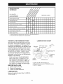
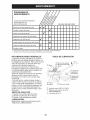
MAI.'rE.A.CE
/ / / / /
sc. ou,
/JSZ oZ#/
SERVICE
REGULAR
SERVICE
_'
Check Engine 0il Level
q/
q/
DATES
q/
tf
Change Engine Oil
_1,2
0il Pivot Points
Inspect Spark Arrester / Muffler
Inspect Air Screen
1_
If
Clean or Replace Air Cleaner Cartridge
Clean Engine Cylinder Fins
6/2
if
Replace Spark Plug
If
1 - Change more often when operating under a heavy load or in high ambient temperatures.
2 - Service more often when operating in dirty or dusty conditions.
GENERAL
RECOMMENDATIONS
LUBRICATION
The warranty on this tiller does not cover
items that have been subjected
to operator abuse or negligence.
To receive full
value from the warranty, the operator must
maintain tiller as instructed
in this manual.
QEngine
CHART
®RH Gear Case
Grease Fitting
Some adjustments
will need to be made
periodically
to properly maintain your tiller.
At least once a season, check to see if
you should make any of the adjustments
described
in the Service and Adjustments
section of this manual.
Stake Pin
@Leveling
Shield
Hinges
• Once a year you should replace the
spark plug, clean or replace air filter,
and check tines and belts for wear. A
Oldler
Bracket
new spark plug and clean air filter assure proper air-fuel mixture and help
your engine run better and last longer.
BEFORE
1.
2.
3.
Check
Check
Check
Hub
O SAE 30 OR 10W-30 Motor Oil
@ Refer to Maintenance "ENGINE"
@ EP #1 Grease
EACH USE
engine oil level.
tine operation.
for loose fasteners.
LUBRICATION
Keep unit well lubricated
TION CHART").
OWheel
(See "LUBRICA-
14
section
_kCAUTION:
Disconnect spark plug
wire before performing any maintenance
(except carburetor adjustment) to prevent
accidental starting of engine.
Prevent fires! Keep the engine free of
grass, leaves, spilled oil, or fuel. Remove
fue! from tank before tipping unit for maintenance. Clean muffler area of all grass,
dirt, and debris.
Do not touch hot muffler or cylinder fins as
contact may cause burns.
4.
5.
ENGINE
Remove oil filler plug. Be careful not
to allow dirt to enter the engine.
Refill engine with oil. See "CHECK
ENGINE OIL LEVEE' in the Operation
section of this manual.
Oil drain
Plug
LUBRICATION
Use only high quality detergent oil rated
with API service classification SG-SL Select the oil's SAE viscosity grade according to your expected temperature.
SAE ViSCOSiTY
=20
0
20
GRADES
40
AIR CLEANER
60
80
L
J
l
J
_
1
=30
=20
=10
0
10
20
TEMPERATURE
RANGE ANTICIPATED
Oil Fill Plug
BEFORE
Service
air cleaner cartridge
every
twenty-five
hours, more often if engine
used in very dusty conditions.
1. Loosen air cleaner screw.
2. Remove air cleaner cover.
100°F
]
30
J
3.
Carefully remove air cleaner cartridge.
Be careful. Do not allow dirt or debris
to fall into carburetor.
4.
Clean
face.
40 ° C
NEXT OiL CHANGE
NOTE: Although multi-viscosity oils
(5W-30, 10W-30, etc.) improve starting
in cold weather, these multi-viscosity oils
will result in increased oil consumption
when used above 40°F (4°C). Check your
engine oil level more frequently to avoid
possible engine damage from running low
on oil.
Change the oil after every 50 hours of operation or at least once a year if the tiller is
not used for 50 hours in one year.
Check the crankcase oil level before
starting the engine and after each five (5)
hours of continuous use. Add SAE 30 motor oil or equivalent. Tighten oil filler plug
securely each time you check the oil level.
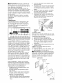
TO CHANGE ENGINE OIL
Determine temperature range expected
before oil change. All oil must meet API
service classification SG-SL
• Be sure tiller is on level surface.
• Oil will drain more freely when warm.
• Use a funnel to prevent oil spill on tiller,
and catch oil in a suitable container.
1. Remove drain plug.
For easier removal of plug use 7/1612 Pt. socket with extension.
2. Tip tiller forward to drain oil.
3. After oil has drained completely,
replace oil drain plug and tighten securely.
is
by tapping
gently
on a flat sur-
NOTE: If very dirty or damaged,
replace
cartridge.
5. Clean and replace cover. Tighten
screw securely.
,_,CAUTION:
Petroleum
solvents, such
as kerosene,
are not to be used to clean
cartridge.
They may cause deterioration
of the cartridge.
Do not oil cartridge.
Do
not use pressurized
air to clean or dry
cartridge.
Air Cleaner
Cartridge
Pre-Cleaner
Cover
15
Air Cleaner
Screws
COOLING
SYSTEM
SPARK PLUG
Your engine is air cooled.
For proper engine performance
and long life keep your
engine clean.
• Clean air screen
frequently
using a
stiff-bristled
brush.
Replace spark plugs at the beginning
of
each tilling season or after every 25 hours
of use, whichever
comes first. Spark plug
type and gap setting are shown in "PRODUCT SPECIFICATIONS"
on page 4 of this
manual.
TRANSMISSION
• Remove blower housing and clean as
necessary.
• Keep cylinder fins free of dirt and chaff.
Your transmission
is sealed
require
unless
lubrication
and will not
serviced.
CLEANING
Do not clean your tiller when the engine
and transmission
are hot. We do not recommend
using pressurized
water (garden
hose, etc.) to clean your unit unless the
gasket area around the transmission
and
the engine muffler, air filter and carburetor
are covered to keep water out. Water in
engine will shorten the useful life of your
tiller.
Air Screen
• Clean engine, wheels, finish, etc. of all
foreign matter.
• Keep finished surfaces
and wheels free
of all gasoline, oil, etc.
• Protect painted surfaces with automotive type wax.
BIo_ver
Housing
MUFFLER
Do not operate tiller without muffler. Do
not tamper with exhaust system. Damaged mufflers or spark arresters could
create a fire hazard. Inspect periodically
and replace if necessary.
If your engine is
equipped
with a spark arrester screen assembly, remove every 50 hours for cleaning and inspection.
Replace if damaged.
,_CAUTION:
Disconnect
spark plug wire
from spark plug and place wire where it
cannot come into contact with plug.
(High) Position
TILLER
TO ADJUST
HANDLE
Handle Lock Lever
HEIGHT
Select handle height best suited for your
tilling conditions.
Handle height will be
different when tiller digs into soil.
1. First loosen handle lock lever.
2.
3.
Handle (Low)
Position
Handle can be positioned
at different
settings between "HIGH" and "LOW"
positions.
Retighten
handle lock lever securely
after adjusting.
16
TIRE
Belt Guard
CARE
_CAUTION:
When mounting
beads are seated, overinflation
Hex
tires, unless
can cause
and
Washer
(Located
Behind
Tire)
an explosion.
• Maintain 20 pounds of tire pressure.
If
tire pressures
are not equal, tiller will
pull to one side.
• Keep tires free of gasoline or oil which
can damage rubber.
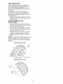
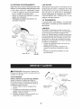
TO REMOVE
WHEEL
1.
Place
blocks
under
transmission
3.
keep tiller from tipping.
Remove hairpin clip and clevis
wheel.
Remove wheel and tire.
4.
Repair
2.
Hairpin Clip and Clevis Pin
to
TO REPLACE
pin from
tire and reassemble.
2.
Remove old belt by slipping off engine
pulley first then remove from transmission pulley.
Place new belt in groove of transmission pulley and into engine pulley.
BELT MUST BE IN GROOVE
ON TOP
OF IDLER PULLEY,
NOTE POSITION
OF BELT TO GUIDES.
4.
Check
below.
BELT
belt adjustment
5.
6.
Replace belt guard.
Reposition
wheel and replace
pin and hairpin clip.
DRIVE
in
as described
clevis
BELT ADJUSTMENT
For proper belt tension, the extension
spring should have about 5/8 inch stretch
when drive control bar is in "ENGAGED"
Hairpin Clip
TO REMOVE
BELT
Remove belt guard as described
"TO REMOVE
BELT GUARD".
GROUND
tire_
DRIVE
1.
3.
evis Pin
GROUND
GUARD
NOTE: For ease of removal, remove hairpin clip and clevis pin from left wheel. Pull
wheel out from tiller about 1 inch.
1. Remove two (2) screws from side of
belt guard.
2. Remove hex nut and washer from
bottom of belt guard (located behind
wheel).
3. Pull belt guard out and away from unit.
4. Replace belt guard by reversing above
procedure.
position.
follows:
1.
2.
3.
This tension
can be attained
as
Loosen cable clip screw securing the
drive control cable.
Slide cable forward for less tension
and rearward for more tension until
about
5/8 inch stretch is obtained while the
drive control bar is engaged.
Tighten cable clip screw securely.
Clip Screw
Engine Pulley
Drive Control Cable
More Tension
Idler Pulley
Extension Spring
Transmission
Pulley
17
TINE
REPLACEMENT
,_CAUT[ON:
gloves
tines.
or other
Tines
are sharp.
protection
when
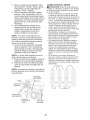
To maintain the superb
mance of this machine
Wear
be checked for sharpness,
wear, and
bending, particularly
the tines which
are next to the transmission.
If the gap
between the tines exceeds 3-1/2 inches
handling
A badly worn tine causes your tiller to
work harder and dig more shallow.
Most
important, worn tines cannot chop and
shred organic matter as effectively
nor
bury it as deeply as good tines. A tine this
worn needs to be replaced.
New Tine
tilling perforthe tines should
they should be replaced or straightened
as necessary.
For tines that are slightly worn, the
bolted tine and hub assemblies
can be
switched
between sides to continue
Worn Tine
tilling in the same tilling mode if tilling
in a different mode is desired then the
bolted tine and hub assemblies
should
be switched
back to their original side
so that the tine edge with the least wear
will be used.
Transmission
,
Tine
'
i
i
--4
3-1/2" MAX
Sharp
Edges
Sharp
Edges
Sharp
Edges
Hairpin Clip
/
20
18
ENGINE
TO ADJUST
Maintenance,
repair, or replacement
of
the emission control devices and systems,
which are being done at the customers
expense, may be performed
by any non-road
engine repair establishment
or individual.
Warranty
repairs must be performed
by an
authorized
engine manufacturer's
service
outlet.
IMPORTANT:
Never tamper with the
engine governor, which is factory set for
proper engine speed.
Overspeeding
the engine above the factory high speed
setting can be dangerous.
If you think
the engine-governed
high speed needs
adjusting,
contact your nearest sears or
other qualified service center which has
the proper equipment
and experience
to
make any necessary
adjustments.
The carburetor has been preset at the
factory and adjustment should not be
necessary. However, engine performance
can be affected by differences in fuel, temperature, altitude or load. If the carburetor
does need adjustment, contact your nearest authorized service center/department
IMPORTANT:
Never tamper with the
engine governor, which is factory set for
proper engine speed. Overspeeding
the engine above the factory high speed
setting can be dangerous. If you think
the engine-governed
high speed needs
adjusting, contact your nearest sears or
other qualified service center which has
the proper equipment and experience to
make any necessary adjustments.
19
CARBURETOR
Immediately
prepare your tiller for storage
at the end of the season or if the unit will
NOTE:
Fuel stabilizer is an acceptable
alternative
in minimizing
the formation
of
fuel gum deposits during storage.
Add
stabilizer to gasoline in fuel tank or storage container.
Always follow the mix ratio
found on stabilizer container.
Run engine
at least 10 minutes after adding stabilizer
to allow the stabilizer to reach the carbure-
not be used for 30 days or more.
_Warning:
Never store the tiller with gasoline in the tank inside a building where
fumes may reach an open flame or spark.
Allow the engine to cool before storing in
any enclosure.
tor. Do not empty the gas tank and carburetor if using fuel stabilizer.
ENGINE OIL
TILLER
1.
2.
3.
4.
5.
Clean entire tiller (See "CLEANING"
in the Maintenance
section of this
Drain oil (with engine warm) and replace
with clean oil. (See "ENGINE"
in the
Maintenance
section of this manual).
CYLINDER
manual).
Inspect and replace belts, if necessary
(See belt replacement
instructions
in
the Service and Adjustments
section of
this manual).
Lubricate as shown in the Maintenance
section of this manual.
1.
2.
3.
Be sure that all nuts, bolts and screws
are securely fastened.
Inspect moving
parts for damage,
breakage
and wear.
Replace if necessary.
Touch up all rusted or chipped paint
surfaces;
sand lightly before painting.
4.
Remove spark plug.
Pour 1 ounce (29 ml) of oil through
spark plug hole into cylinder.
Pull starter handle slowly several times
to distribute oil.
Replace with new spark plug.
OTHER
• Do not store
to another.
ENGINE
gasoline
from one season
•
Replace your gasoline can if your can
starts to rust. Rust and/or dirt in your
gasoline will cause problems.
• If possible, store your unit indoors and
cover it to give protection
from dust and
dirt.
FUEL SYSTEM
IMPORTANT:
It is important
to prevent
gum deposits from forming in essential
fuel system parts such as the carburetor,
fuel filter, fuel hose, or tank during storage. Also, alcohol blended fuels (called
gasohol or using ethanol or methanol)
can
attract moisture which leads to separation
and formation
of acids during storage.
Acidic gas can damage the fuel system of
an engine while in storage.
• Empty the fuel tank by starting the engine and letting it run until the fuel lines
and carburetor
are empty.
• Never use engine or carburetor
cleaner
products in the fuel tank or permanent
damage may occur.
• Use fresh fuel next season.
• Cover your unit with a suitable protective cover that does not retain moisture.
Do not use plastic.
Plastic cannot
breathe which allows condensation
to
form and will cause your unit to rust.
IMPORTANT:
Never cover tiller while engine and exhaust
20
areas
are still warm.
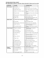
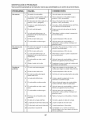
TROUBLESHOOTING CHART:
See appropriate section in manual unless directed to Sears service center
PROBLEM
Will not start
Hard to start
Loss of power
Engine
overheats
CAUSE
CORRECTION
1
Out of fuel.
1
Fill fuel tank.
2
Fuel valve "OFF"
2
Turn fuel valve to the "ON" position.
3
Engine Switch "OFF"
3
Turn engine switch to the "ON" position.
4
Engine not "CHOKED"
4
See "TO START ENGINE"
section.
5
Engine flooded.
5
Wait several minutes before attempting
to start.
6
Bad spark plug or improper gap.
6
Replace spark plug or adjust gap.
7
Dirty air filter.
7
Clean/replace
8
Water in fuel.
8
Empty fuel tank and carburetor,
tank with fresh gasoline.
1
Throttle control not set properly.
1
See "To Start Engine" in Operations
section.
2
Dirty air filter.
2
Clean/replace
3
Bad spark plug or improper gap.
3
Replace spark plug or adjust gap.
4
Stale or dirty fuel.
4
Empty fuel tank and refill tank with
fresh, clean gasoline.
5
Loose spark plug wire.
5
Make sure spark plug wire is seated
properly.
1
Engine is overloaded
1
Set depth stake and wheels for
shallower tilling.
2
Dirty air cleaner
2
Clean/replace
3
Low oil level/dirty
3
Check oil level/change
4
Faulty spark plug.
4
Clean and regap or change spark plug.
5
Oil in fuel
5
Empty and clean fuel tank and refill,
and clean carburetor.
6
Stale or dirty fuel.
6
Empty fuel tank and refill tank with
fresh, clean gasoline.
7
Water in fuel.
7
Empty fuel tank and carburetor,
tank with fresh gasoline.
8
Clogged fuel tank.
8
Remove fuel tank and clean.
9
Spark plug wire loose.
9
Connect and tighten spark plug wire.
10
Dirty engine air screen.
10
Clean engine air screen.
11
Dirty/clogged
11
Clean/replace
12
Poor Compression
12
Contact a Sears or other qualified
service center.
1
Low oil level/dirty
2
properly.
oil.
muffler.
oil.
in Operation
air filter.
air filter.
air filter.
oil.
refill
muffler.
1
Check oil level/change
Dirty engine air screen.
2
Clean engine air screen.
3
Dirty engine.
3
Clean cylinder fins, airscreen,
area
4
Partially plugged muffler
4
Remove and clean muffler.
21
refill
oil.
muffler
TROUBLESHOOTING CHART:
See appropriate section in manual unless directed to Sears service center
PROBLEM
CAUSE
CORRECTION
1
Ground too dry and hard.
1
Moisten ground or wait for more
favorable soil conditions
2
Wheels and depth stake
incorrectly adjusted.
2
Adjust wheels and depth stake.
Soil bails up
or clumps
1
Ground too wet.
1
Wait for more favorable
Engineruns
1
Tine control is not engaged.
1
Engage tine control
2
V-belt not correctly adjusted.
2
Inspect/adjust
3
V-belt is off pulley (s).
3
Inspect V-belt.
Engine runs
but labors
1
Tilling too deep.
1
Set depth stake for shallower
when tilling
2
Throttle control not properly
adjusted.
2
Check throttle control setting.
Excessive
bounce/
difficult
handling
buttiller
won't
move
22
conditions.
V-belt.
tilling
Garantia .......................................................
Reglas de Seguridad ...................................
Especificaciones del producto .....................
Montaje/Pre-Operaci6n
...............................
Operaci6n ....................................................
Programa de Mantenimiento .......................
GARANTIA
23
23
25
27
29
35
Mantenimiento .............................................
35
Servicio y Ajustes .......................................
37
AImacenamiento ..........................................
41
Identificaci6n de Problemas ........................ 42
Vea el Manual Ingles ............ Ingles del Dueflo
LIMITADA DE DOS ANOS PARA LA CULTIVADORA
CRAFTSMAN
Por dos (2) aflos, a partir de la fecha de compra, cuando esta Cultivadora Craftsman se mantenga,
lubrique y afine segOn las instrucciones para la operaci6n y el mantenimiento en el manual del
dueflo, Sears reparara, gratis, todo defecto en el material y la mano de obra.
Esta Garantia no cubre:
• Articulos que se desgastan durante el uso normal tales como los brazos, las bujias, los filtros de
aire y las correas.
• Reparaciones necesarias debido al abuso o a la negligencia del operador, incluyendose a los
cigOeflales doblados y a la falta de mantenimiento del equipo seg0n las instrucciones que se
incluyen en el manual del dueflo.
• Si la Cultivadora Craftsman se usa para fines de arriendo, esta garanfia se aplica solamente por
treinta (30) treintadias a partir de la fecha de compra.
El Servicio de Garantia esta disponible al devolver la cultivadora
de servicio Sears m_,s cercano en los estados unidos.
Craftsman al centro/departamento
Esta Garantia se aplica solamente mientras el producto este en uso en los estados unidos. Esta
Garantia le otorga derechos legales especificos, y puede que tambien tenga otros derechos que
varian de estado a estado.
SEARS, ROEBUCK AND CO., D/817WA, HOFFMAN
ESTATES, IL 60179
U.S.A.
IMPORTANTE: Esta Maquina cortadora es capaz de amputar las manosy los pies y de lanzar
objetos, si no se observan las instrucciones de seguridad siguientes se pueden producir lesiones
graves o la muerte.
• Nunca aflada combustible a un motor en
funcionamiento o caliente.
• Llene el estanque de combustible afuera con
mucho cuidado. Nunca Ilene el estanque de
combustible en un recinto cerrado.
• Vuelva a colocar la tapa del dep6sito de
gasolina en forma segura y limpie el combustible derramado antes de volver a arrancar.
• Use cordones de extensi6n y receptaculos,
seg0n las especificaciones del fabricante,
para todas las unidades con motores de impulsi6n o con motores de arranque electrico.
• Nunca trate de hacer ningOn ajuste mientras
que el motor este funcionando (excepto en
los casos especificamente recomendados
por el fabricante).
ENTRENAMIENTO
• Lea el Manual del Dueflo cuidadosamente.
Familiaricese completamente con los
controles y con el uso adecuado del equipo.
Sepa c6mo parar la unidad y desenganchar
los controles rapidamente.
• Nunca permita que los niflos operen el equipo. Nunca permita que los adultos operen el
equipo sin los conocimientos adecuados.
• Mantenga el area de operaci6n despejada de
personas, especialmente niflos pequeflos y
animales domesticos.
PREPARACION
• Inspeccione cuidadosamente el &rea en
donde se va usar el equipo y remueva los
objetos extraflos.
• Desenganche todos los embragues y cambie
a neutro antes de hacer arrancar el motor.
• No opere el equipo sin usar ropa exterior
adecuada. Use zapatos que mejoren el equilibrio en superficies resbalosas.
• Maneje el combustible con cuidado pues es
muy inflamable.
• Use un envase de combustible aprobado.
OPERACION
• No ponga ni las manos ni los pies cerca o
debajo de las piezas rotatorias.
• Tenga mucho cuidado cuando opere o cruce
entradas para autom6viles de ripio, senderos
o caminos. Este alerta en Io que se refiere a
los peligros escondidos o al trafico. No Ileve
pasajeros.
23
MANTENIMIENTO
• Despues de pegarle a un objeto extraflo,
pare el motor, remueva el alambre de la
bujia, inspeccione la cultivadora cuidadosamente, para verificar si hay daflos, y repare
el daflo antes de volver a arrancar y operar
la cultivadora.
• Tenga cuidado para evitar resbalarse o
caerse.
• Si la unidad empieza a vibrar anormalmente,
pare el motor y revisela inmediatamente para
verificar la causa. La vibraci6n normalmente
es un aviso de problemas.
• Pare el motor cuando abandone la posici6n
de operaci6n.
• Tome todas las precauciones posibles
cuando deje la m&quina desatendida. Desenganche los brazos, cambie a neutro y pare el
motor.
• Antes de limpiar, reparar e inspeccionar,
apague el motor y asegQrese que todas
las partes en movimiento se han detenido.
Desconecte el alambre de la bujia, y mantengalo alejado de esta para evitar el arranque
pot accidente. Desconecte el cord6n en los
motores electricos.
• No haga funcionar el motor en recintos cerrados; los gases de escape son peligrosos.
• Nunca opere la cultivadora sin las protecciones, y las planchas adecuadas y sin los
demas dispositivos de seguridad en su lugar.
• Mantenga a los niflos y a los animales domesticos alejados.
• No sobrecargue la capacidad de la maquina,
tratando de cultivar a mucha profundidad,
muy rapido.
• Nunca opere la maquina a altas velocidades
en superficies resbalosas. Mire hacia atras y
tenga cuidado cuando retroceda.
• Nunca permita la presencia de espectadores
cerca de la unidad.
• Use solamente accesorios y aditamentos
para la cultivadora aprobados por el fabricante.
• Nunca opere la cultivadora sin buena visibilidad o luz.
• Tenga cuidado al cultivar en terreno duro.
Los brazos pueden quedarse agarrados en
el suelo e impulsar a la cultivadora hacia
adelante. Si esto sucede, suelte los mangos
y no restrinja la m&quina.
Y ALMACENAIVIIENTO
• Mantenga los accesorios y aditamentos de
la m&quina en buenas condiciones para el
funcionamiento.
• Revise las clavijas de seguro, los pernos
de montaje del motor y otros pernos, a
intervalos frecuentes, para verificar si estan
apretados en forma segura y asegurarse que
el equipo este en buenas condiciones de
funcionamiento.
• Nunca guarde la maquina con combustible
en el estanque de combustible dentro de un
edificio en donde hay fuentes de ignici6n
presentes, tales como calentadores de agua
o del ambiente, secadoras de ropa u otros
artefactos parecidos. Permita que se enfrie
el motor antes de guardarlo en algQn lugar
cerrado.
• Siempre refierase alas instrucciones en la
guia del operador para vet los detalles de importancia si la cultivadora va a ser guardada
por un periodo de tiempo largo.
Ai_Busque este simbolo que seflala las precauciones de segqridad de importancia. Quiere
decir - iiiATENCION!!!
iiiESTE ALERTO!!! SU
SEGURIDAD ESTA COMPROMETIDA.
_i_PREOAUCI6N:
Siempre desconecte el
alambre de la bujia y p6ngalo donde no pueda
entrar en contacto con la bujia, para evitar el
arranque pot accidente, durante la preparaci6n,
el transporte, el ajuste o cuando se hacen
reparaciones.
_DVERTENCIA:
El tubo de escape del
motor, algunos de sus constituyentes y algunos
componentes del vehiculo contienen o desprenden productos quimicos conocidos en el
Estado de California como causa de c&ncer y
defectos al nacimiento u otros daflos reproductivos.
24
ESPECIFICACIONES
DEL
PRODUCTO
Capacidad de gasotina:
3 Cuartos (2.8L)
Sin ptomo, regular
Aceite (API-SG-SL):
(Capacidad:20 oz./0.6L)
SAE 30 (Sobre 32°F)
SAE 5W-30
(Debajo 32°F)
Bujia:
(Abertura: .030"/0.76mm)
NGK-BPR6ES
TORCH-F6RTC
ACUERDOS
DE PROTECCION
PARA
LA REPARACION
Congratulaciones
por su buena compra.
Su nuevo producto Craftsman® est& diseflado
y fabricado para funcionar de modo fiable por
muchos aflos. Pero como todos los productos,
puede necesitar alguna reparaci6n de tanto
en tanto. En este caso tenet un Acuerdo de
Protecci6n para la Reparaci6n puede hacerles
ahorrar dinero y fastidios.
Compre ahora un Acuerdo de Protecci6n para
la Reparaci6n y protegese de molestias y gastos inesperados.
Un Acuerdo incluye los puntos siguientes:
• Servicio experto de nuestros 12.000 especialistas profesionales en la reparaci6n.
• Servicio ilimitado sin cargo alguno para
las partes y la mano de obra sobre todas las
reparaciones garantizadas.
• Sustituci6n del producto si su producto
garantizado no puede set arreglado.
• Descuento del 10% sobre el precio corriente
del servicio y de las partes relativas al servicio no cubiertas pot el acuerdo; tambien el
10% menos sobre el precio corriente de un
control de mantenimiento preventivo.
• Ayuda r_pida pot telefono - soporte
telef6nico por parte de un tecnico Sears
sobre productos que requieren un arreglo en
casa, y adem&s una programaci6n sobre los
arreglos m&s convenientes.
Cuando se ha comprado el Acuerdo, basta con
una Ilamada telef6nica para programar el servicio. Puede Ilamar cuando quiera, dia y noche o
fijar en linea una cita para obtener el servicio.
Sears tiene m&s de 12.000 especialistas
profesionales en la reparaci6n, que tienen
acceso a mas de 4.5 millones de partes y
accesorios de calidad.
Este es el tipo de profesionalidad con que
puede contar para ayudar a alargar la vida del
producto que acaba de comprar, por muchos
aflos, iCompre hoy su Acuerdo de Protecci6n
para la Reparaci6n!
Se aplican algunas limitaciones y exclusiones. Para conocer los precios y tenet
rn_s Inforrnaci6n,
Ilame al 1=800=827=6655.
SERVlClO
DE INSTALAClON
SEARS
FELIClTAClONES
pot la compra de su Cultivadora Sears. Ha sido diseflada, planificada y
fabricada para darle la mejor confiabilidad y el
mejor rendimiento posible.
En el caso de que se encuentre con cualquier
problema que no pueda solucionar f&cilmente,
haga el favor de ponerse en contacto con un
centro de servicio Sears o con un otto centro
de servicio cualificado. Cuenta con tecnicos
bien capacitados y competentes con herramientas adecuadas para darle servicio o para
reparar su unidad.
Haga el favor de leer y de guardar este manual.
Estas instrucciones le permitir&n montar y
mantener su cultivadora en forma adecuada.
Siempre observe las "REGLAS DE SEGURIDAD."
RESPONSABILIDADES
DEL CLIENTE
• Lea y observe las reglas de seguridad.
• Siga un programa regular de mantenimiento,
cuidado y uso de su cultivadora.
• Siga las instrucciones descritas en las secciones "Mantenimiento" y '_,lmacenamiento"
de este Manual del Dueflo.
_,DVERTENCIA:
Esta unidad viene equipada con un motor de combusti6n interno y no se
debe usar sobre, o cerca, de un terreno no desarrollado cubierto de bosques, de arbustos o
de cesped, a menos que el sistema de escape
del motor venga equipado con un amortiguador
de chispas que cumpla con las leyes locales o
estatales (si existen). Si se usa un amortiguador de chispas, el operador debe mantenerlo
en condiciones de trabajo eficientes.
En el estado de California, la ley exige Io anterior (Secci6n 4442 del "California Public Resources Code" [Decreto de Recursos PQblicos
de California]). Otros estados pueden contar
con otras leyes parecidas. Las leyes federales
se aplican en las tierras federales. Su centro
de Servicio m&s cercano tiene disponible amortiguadores de chispas para el silenciador. (Vea
la secci6n de Partes de Repuesto en el manual
Ingles del dueflo.)
Para la instalacidn profesional Sears de aparatos de casa, puertas de garaje, calentadores de
agua y otros importantes
articulos para la casa, en U.S.A Ilamar a
1=800=4=MY=HOME®
25
Estos accesorios estaban disponibles cuando se compr6 la cultivadora. Tambien estan disponibles
en la mayoria de las tiendas de Sears yen los centros de servicio. La mayoria de las tiendas
Sears tambien pueden ordenar partes de repuesto para usted, si les proporciona el nOmero del
modelo de su cultivadora.
MOTOR
BUJOA
StLENCtADOR
RENDIMIENTO
ABRIDOR
FILTRO
DE AIRE
LATA
DE GASOLINA
ACEITE
DEL
MOTOR
ESTABtLIZADOR
DE LA CULTIVADORA
DE SURCOS
MANTENIMIENTO
DE LA CULTIVADORA
CORREA
BRAZOS
CONTENIDO
(2) Cierres del mango
/__
' (1) Abrazaderas
CLAVIJA
DE SEGURO
ABRAZADERA
DE HORQUILLA
DEL CONJUNTO DE FERRETER|A
G LI
(1) Tuerca de
seguridad
(1) Perno portadores
de centro
3/8-16
UNC (1)Abrazadera
3/8-16 UNC x 1 clase 5
de cable
de
/
_"_
/
(1) Perno articulado
3/8-16 UNC Clase 5
horquilla
(1) Arandela plana
13/32xlx11Ga.
°1
(2) Clavijade
& retencion
seguro
©
(1)Palanca
26
de cierre del mango
Su cultivadora nueva ha sido montada en la f_tbrica, con la excepci6n de aquellas partes que se
dejaron sin montar por razones de envio. Para asegurarse que la cultivadora operara en forma
segura y adecuada, todas las partes y los articulos de ferreteria que monte tienen que estar apretados en forma segura. Use las herramientas correctas, segQn sea necesario, para asegurarse de
que queden apretadas en forma segura.
HERRAMIENTAS
NECESARIAS
PARA
EL MONTAJE
Se le facilitar& el montaje si cuenta con un
juego de Ilaves de tubo. Se han enumerado los
tama_os estandar de las Ilaves.
(1) Cuchillo para todo uso
(1) Cortador de alambres
(1) Destornillador
(1) Medidor de presi6n de las Ilantas
(1) Par de alicates
(1) Llave de 9/16"
POSICl6N DEL OPERADOR
Cuando en este manual se mencionan los
terminos "lado derecho" o "lado izquierdo"
se refiere a cuando usted se encuentra en la
posici6n de operaci6n (parado/a detras de los
mangos de la cultivadora).
4.
5.
Varilla de Cambio
\
Oonjunto del
Mango
PARTE DELANTERA
INSTALACION DEL MANGO
1. Inserte un cierre del mango (con los dientes
mirando hacia afuera) en la muesca de la
caja de cambio. (Aplique grasa en el lado
liso del cierre del mango para ayudar a
mantenerlo en su lugar hasta que el conjunto del mango se baje a su posici6n.)
LADO
DERECHO
LADO
IZQUIERDO
Corte la esquina del lado derecho delantera
y la trasera de la caja de cart6n. Tienda
en el suelo la pared lateral de la caja de
cart6n.
Remueva el material de empaque del conjunto del mango.
VISTA DESDE EL LADO DERECHO DE LA
CULTIVADORA
Conjunto del Mango
esca de la Caja de Cambio
\
Oierre det Mango
POSICI6N DEL
OPERADOR
DESEMPAQUE
CARTON
DE LA CAJA DE
,
AI_,PRECAUCI6N: Tenga cuidado con las grapas expuestas cuando maneje o deseche los
materiales de la caja de cart6n.
IMPORTANTE:
Cuando desempaque y monte
la cultivadora, tenga cuidado de no estirar o
enredar los cables.
1. AI mismo tiempo que se sujeta el conjunto
del mango, corte las ligaduras del cable que
aseguran el conjunto del mango al bastidor
superior y a la estaca de profundidad. Permita que el conjunto del mango descanse
en la cultivadora.
2. Remueva el bastidor superior de la caja de
cart6n.
3. Lentamente, saque el conjunto de! mango
hacia arriba y p6ngalo en la parte superior
de la caja de cart6n.
Agarre el conjunto del mango. Mantengalo
en la posici6n "arriba." AsegQrese que el
cierre del mango permanezca en la muesca
de la caja de cambio. Deslice el conjunto
del mango a su posici6n.
Oonjunto det mango
posoci6n 'Arriba"
Apriete la palanca de
cierre det mango para
etarla
Suette la patanca de
cierre del mango para
moverla
27
3.
Rote el conjunto del mango hacia abajo. Inserte el perno portador trasero primero, con
la cabeza del perno en el lado izquierdo de
la cultivadora y ponga sueltamente la tuerca
de seguridad.
4. Inserte el perno de pivote de la parte delantera de la placa y apriete en forma segura.
5. Corte la esquina del lado izquierdo trasera
de la caja de cart6n. Tienda en el suelo la
pared trasera del cart6n, la cual removera
la solapa protectora de cart6n de la defensa
de nivelaci6n.
6. Corte las esquinas restantes del cart6n y
p6ngalas planas.
7. Baje el conjunto de mango. Apriete la
tuerca del perno de acarreo para que e!
mango pueda moverse con alguna resistencia. Esto facilitara el ajuste.
8. Ponga la arandela plana en el extremo
roscado de la palanca de cierre del mango.
9. Inserte la palanca de cierre del mango a
traves de la base del mango y de la caja de
engranaje. Atornille la palanca de seguridad
del mango, justo Io suficiente como para
sujetar la palanca en su lugar.
10. Inserte el segundo cierre del mango (con
los dientes hacia adentro) en la ranura en
la base del mango (justo dentro de la arandela).
11. Con el conjunto del mango en la posici6n
mas baja, apriete la palanca de cierre del
mango, en forma segura, rotandola en el
sentido de las manillas del reloj. Si se deja
el conjunto del mango en la posici6n mgts
baja, sergt mas fgtcil remover la cultivadora
de la caja de cart6n.
Cotumna det
Mango
Cables
&brazadera del
Cable
handles
CONEXION DE LA VARILLA DE CAMBIO
1. Inserte el extremo de la varilla de cambio
que est& mgts alejado de la dobladura, en
el agujero del indicador de la palanca de
cambio.
2. Inserta la abrazadera de horquilla a traves
del agujero de la varilla de cambio para
asegurarla con la junta de la abrazadera
sobre el lado derecho.
Abrazadera de Horquilla
Indicador de la
de Cambio
Varilla de Cambio
REMOCION
DE LA CULTIVADORA
DE
LA CAJA
1. Ajuste el conjunto del mango a la posici6n
la mas baja. AsegOrese que el mango de
cierre este bien seguro.
2. AsegOrese que el indicador de la palanca
de cambio este en la posici6n neutro "N".
3. Incline la cultivadora hacia adelante levantando el mango. Separe la cubierta de
cart6n de la defensa de nivelaci6n.
4. Rote el mango de la cultivadora a la derecha y tirela fuera de la caja de cart6n.
REVISION
DE LA PRESlON
DE LAS
LLANTAS
Las Ilantas en su unidad se inflaron demasiado
en la fgtbrica por razones de envio. Es importante que las Ilantas tengan la misma presi6n y
que esta sea la correcta para obtener el mejor
rendimiento en el labrado.
• Reduzca la presi6n de las Ilantas a 20 PSI.
ALTURA
DEL MANGO
• Se puede ajustar la altura del mango en la
mejor forma que le acomode al operador.
(Vea "PARA AJUSTAR LA ALTURA DEL
MANGO" en la secci6n de Servicio y Ajustes
de este manual.)
Arandeta Plana
Cierre delNMango
Caja de Cambio
Palanca de
Cierre det Mango
Perno portador
trasero
Base del Mango
14
Bouton de
" _)
pivot
Tuercas de Seguridad
INSERClON DE LA ABRAZADERA
DEL
CABLE
• Inserte la abrazadera del cable de pl&stico
dentro del agujero en la parte trasera de
la columna del mango. Empuje los cables
dentro de la abrazadera.
28
Estos simbolos pueden apareser sobre su cultivadora
ducto, aprenda y comprenda sus significados.
CONOZCA
en la literature proporcionada
con el pro-
SU CULTIVADORA
LEA ESTE MANUAL DEL DUENO Y LAS REGLAS
CULTWADORA
DE SEGURIDAD
ANTES DE OPERAR SU
Compare las ilustraciones con su cultivadora para familiarizarse
con la ubicaci6n
diversos controles y ajustes. Guarde este manual para futura referencia.
de los
MARCHA
N
LABOREO
LABOREO
MARCHA
HACIA
NEUTRO
ATTENO,0NOMOTOR
MOTOR
REVES
ADVERTENCIA
ENCENDIDO
APAGADO
I
ESTRANOOMO AOE,TE
RETEN O
LACION
BUSTIBLE
V&tvuta de
combustible
Control de la aceleraci6n
Interruptorde
ON/OFF
Patanca de cambio
control
de la
estrangutaciOn
Mango del
de cutateo
Barra de control de
la imputsi6n
Indicador de la palanca
Estaca de
Estaca de
Defensa de
nivelaci6n "--_
Defensa latera
exterior
Nuestras cultivadoras cumplen con los est&ndares de seguridad del
American National Standards Institute.
BARRA DE CONTROL
DE LA IMPULSION
=
Se usa para enganchar los brazos.
CONTROL DE LA ACELERACION
= Controla
la velocidad del motor.
CONTROL DE LA ESTRANGULACION
= Utilizado para arrancar con motor frio.
DEFENSA DE NIVELACION = Nivela el suelo
labrado.
DEFENSA LATERAL EXTERIOR = Ajustable
para no enterrar las plantas pequeSas.
ESTACA DE PROFUNDIDAD = Controla la
profundidad a la cual excavar& la cultivadora.
ESTACA DE ARRASTRE = Controla la velocidad de marcha hacia adelante.
INDICADOR DE LA PALANCA DE CAMBIO
= Muestra en que cambio de engranaje se
encuentra la transmisi6n.
INTERRUPTOR DE ON / OFF = Utilizado para
parar (STOP) el motor.
MANGO DEL ARRANCADOR
DE CULATEO = Se usa para hacer arrancar el motor.
PALANCA DE CAMBIO = Se usa para cambiar
los engranajes de la transmisi6n.
Vh, LVULA DE COMBUSTIBLE = Apagaba
combustible yen.
29
SEGURIDAD
La operaci6n de cualquier cultivadora puede hacer que salten objetos extraflos dentro de sus ojos, Io que puede producir daflos graves en estos. Siempre use anteojos
de seguridad o protecciones para los ojos antes de hacer arrancar su cultivadora o
mientras este labrando con ella. Recomendamos gafas de seguridad o una m&scara de visi6n amplia de seguridad usada sobre las gafas.
COMO UTILIZAR
LA CULTIVADORA
OPERACION DE LOS BRAZOS - CON
IMPULSION DE RUEDAS
Sepa c6mo utilizar todos los controles antes
de agregar combustible
y aceite, o antes de
intentar arrancar el motor.
DETENCION DE LA MAQUINA
• Siempre suelte la barra de control de la impulsi6n antes de mover la palanca de cambio
a otra posici6n.
• El movimiento de los dientes se Iogra al
mover la palanca de cambio cualquiera de la
contra rotaci6n (_) posici6n para segar y enganchando la barra de control de mando. (_)
posici6n para segar o la posici6n de rotaci6n
hacia delante.
MARCHA HAClA ADELANTE - RUEDAS SO=
LAMENTE/BRAZOS
PARADOS
• Suelte la barra de control de la impulsi6n y
mueva el indicador de la palanca de cambio
a la posici6n "F" (marcha hacia adelante).
Enganche la barra de control de la impulsi6n
y la cultivadora se mover& hacia adelante.
MARCHA ATRAS - RUEDAS SOLA MENTE/
BRAZOS PARADOS
1. NO SE PARE DIRECTAMENTE DETRAS
DE LA CULTIVADORA.
2. Suelte la barra de control de la impulsi6n.
3. Mueva el control de la aceleraci6n a la
posici6n de "LENTO" (SLOW).
4. Mueva el indicador de la palanca de cambio
a la posici6n de "R" (marcha atr&s).
5. Sujete la barra de control de la impulsi6n en
contra del mango para hacer arrancar en
movimiento a la cultivadora.
ES DIFiCIL CAMBIAR LAS MARCHAS
• Enganche lentamente la barra de control de
la transmisi6n y suelte o bascule la
cultivadora hacia adelante y hacia atr&s hasta que
sea posible cambiar las marchas.
LOS DIENTES
1. Suelte la barra de control de la impulsi6n
para parar el movimiento.
2. Mueva la palanca de cambio a la posici6n
de neutro ("N").
EL MOTOR
2. Mueva el control del regulador hasta la
posici6n <_SLOW>_(lento) y deje que el motor
funcione lentamente para que se enfrie.
3. Gire el interruptor del motor hasta la posici6n
<_OFF>_(apagado).
4. Gire la palanca de la v&lvula de combustible
hasta la posici6n <_OFF>>(apagado).
NOTA: nunca utilice el obturador para detener
el motor.
IMPORTANTE: para detener el motor en caso
de emergencia, gire el interruptor del motor
hasta la posici6n de APAGADO.
Barra de control de la
imputsi6n en la posici6n
"Eng_
Patanca de
cambio
Barra de control de la
imputsi6n en la posici6n
"Disenganchada"
Control del
regulador
Interruptor
del motor
V&lvula de
combustible
ESTACA
DE PROFUNDIDAD
La estaca de profundidad puede levantarse o
bajarse para permitirle un labrado m&s vers&til
o para facilitar el transporte de su cultivadora.
Labrado menos
profundo
(Cultivating)
Control del
reg
Posici6n de
Transporte
Labrado M&s
profundo /
_ Estaca de profundidad
V&lvula de
combustible
V&lvula de
combustible
30
ESTACA
DE ARRASTRE
La estaca de arrastre debe estar levantada
cuando este cultivando en el modo de contra
rotaci6n (_).
La estaca de arrastre debe set bajada cuando
se esta cultivando en el modo de rotaci6n hecia
delante (_,).
.
Bajada (Sega de rota_
hacia delante)_
Levantada (Sega de
contra rotaci6n)_--____._
LABRADO
AVlSO: Utilice el control de transmisi6n de
contra rotaci6n cuando este cultivando fuertemente, o el terreno sea montahoso, o la tierra
sea virgen, o sea cesped.
1. Suelte la clavija de la estaca de profundidad. Tire la estaca de profundidad hacia
arriba para aumentar la profundidad del
labrado. Ponga la clavija de la estaca de
profundidad en el agujero de la estaca de
profundidad para cerrarla en su posici6n.
2. Ponga _,indicador de la palanca de cambio
en la (_) posici6n.
3. Sujete la barra de control de la impulsi6n
en contra del mango para empezar con el
movimiento de labraci6n. Tanto los brazos
como las ruedas van a girar.
4. Mueva el control de la aceleraci6n a la
posici6n de "R,_PIDO" (FAST) para un
labrado profundo.
IMPORTANTE: Siempre suelte la barra de control de la impulsi6n antes de mover la palanca
de cambio a otra posici6n.
Posici6n "Oerrada"
Defensa lat_
exterior
Clavija de
ta estaca de
_rofundidad
en la posici6n
"Suelta"
GIRO
1. Suelte la barra de control de la impulsi6n.
2. Mueva el control de la aceleraci6n a la
posici6n de "LENTO" (SLOW).
3. Ponga el indicador de la palanca de cambio
en la posici6n de "F" (marcha hacia adelante). Los brazos no van a girar.
4. Levante el mango para levantar los brazos
fuera del suelo.
5. Mueva el mango en la direcci6n opuesta
en la que desea girar, con cuidado de mantenet los pies y las piernas alejados de los
brazos de la cultivadora.
31
Cuando haya completado su vuelta, suelte
la barra de control de la impulsi6n y baje el
mango. Ponga la palanca de cambio en la
posici6n labrado y mueva el control de la
aceleraci6n a la velocidad deseada. Para
empezar a cultivar, sujete la barra de control de la impulsi6n en contra del mango.
CULTIVO
AVlSO: Use el diente de rotaci6n delantera
cuando este cultivando, cultivando terreno
mullido o cultivando terreno preparado a la
cultivaci6n.
1. Suelte el pasador de staca de profundidad.
Tire de la estaca de profundidad para aumentar la profundidad del cultivo. Levantar
la estaca de arrastre. Ponga el pasador de
la estaca de profundidad en el agujero de
la estaca o de la estaca de arrastre, para
cerrar en posici6n.
2. Ponga el indicador de la palanca de cambio
en la ('_) posici6n.
3. Sujete la barra de control de la impulsi6n
en contra del mango para empezar con el
movimiento de labraci6n. Tanto los brazos
como las ruedas van a girar.
4. Mueva el control de la aceleraci6n a la
posici6n de "RAPIDO" (FAST) para un labrado profundo. Para cultivar, el control de la
aceleraci6n puede set ajustado a cualquier
velocidad deseada, dependiendo de cu&n
r&pido o cu&n lento desee hacer el cultivo.
IMPORTANTE: Baje siempre la estaca de arrastre antes de utilizar el mando de diente de
rotaci6n hacia adelante.
DEFENSAS
LATERALES
EXTERIORES
Los bordes trasero de las defensas laterales
exteriores son rasurados de modo que estas
se puedan levantar para hacer un labrado
profundo y bajar para uno poco profundo, para
evitar enterrar las plantas pequehas.
1. Suelte latuerca'_' en la ranuray latuerca"B".
2. Mueva la defensa a la posici6n deseada (en
ambos lados).
3. Vuelva a apretar las tuercas.
PARA EL TRANSPORTE
_PRECAUCl6N:
Antes de levantarla o transportarla, permita que el motor de la cultivadora
y el silenciador se enfrien. Desconecte el alambre de la bujia. Drene la gasolina del estanque
de combustible.
EN EL JARDiN
1. Suelte la clavija de la estaca de profundidad. Mueva la estaca de profundidad hacia
abajo, al agujero superior, para transportar
la cultivadora. Ponga la clavija de la estaca
de profundidad en el agujero de la estaca
de profundidad para asegurarla en su lugar.
Esto impide que los brazos se arrastren por
el suelo.
2. Ponga el indicador de la palanca de cambio
en la posici6n de "F" (marcha hacia adelante) para el transporte.
3. Sujete la barra de control de la impulsi6n
en contra del mango para empezar con el
movimiento de la cultivadora. Los brazos no
van a girar.
4. Muevael controlde laaceleraci6na la
velocidaddeseada.
ENLA ClUDAD
1. Desconecte
el alambrede labujia.
2. Dreneel estanquedecombustible.
3. Transp6rtela
en la posici6nderechahacia
arribaparaevitarlafugadelaceite.
ANTES
DE ARRANCAR
AGREGUE GASOLINA
• Llene el estanque de combustible. Llene
hasta la parte inferior del cuello de relleno del estanque de gasolina. No Io Ilene
demasiado. Use gasolina regular, sin plomo,
nueva y limpia con el minimo de 87 octanos.
(El uso de gasolina con plomo aumentar&
los dep6sitos de 6xido de plomo y carbono
y se reducir& la duraci6n de la v&lvula).
No mezcle el aceite con la gasolina. Para
asegurar que la gasolina utilizada sea fresca
compre estanques los cuales puedan ser
utilizados durante los primeros 30 dias.
_PRECAUCION:
Llene el estanque de
combustible hasta dentro de 1/2 pulgada de la
parte superior para evitar los derrames y para
permitir que se expanda el combustible. Si por
casualidad se derrama la gasolina, aleje la
m&quina del &tea del derrame. Evite crear cualquiera fuente de ignici6n hasta que se hayan
desaparecido los gases de la gasolina.
Limpie el aceite o el combustible derramado.
No almacene, derrame o use gasolina cerca de
una llama expuesta.
IMPORTANTE: Cuando se opere en temperaturas por debajo de 32°F (0°C) use gasolina de
invierno limpia y nueva para auedar a asegurar
un buen arranque en clima frio.
PRECAUClON: Combustibles mezclados con
alcohol (conocidos como gasohol, o el uso de
etanol o metanol) pueden atraer la humedad,
la que conduce a la separaci6n y formaci6n de
&cidos durante el almacenamiento. La gasolina
acidica puede dahar el sistema del combustible
de un motor durante el almacenamiento.
Para
evitar los problemas con el motor, se debe vaciar el sistema de combustible antes de guardarlo por un periodo de 30 dias o m&s. Vacie
el estanque de combustible, haga arrancar el
motor y h&galo funcionar hasta que las lineas
del combustible y el carburador queden vacios.
La pr6xima temporada use combustible nuevo.
Vea las Instrucciones para el Almacenamiento
para m&s informaci6n. Nunca use productos de
limpieza para el motor o para el carburador en
el estanque del combustible pues se pueden
producir dahos permanentes.
EL MOTOR
IMPORTANTE: tenga mucho cuidado y evite
que ingrese suciedad en el motor al controlar
o agregar aceite o combustible. Utilice aceite y
combustible limpios, y almacenelos en recipientes con tapa, limpios y aprobados. Utilice
embudos limpios.
LLENE EL MOTOR CON ACEITE
1. Retire la etiqueta colgante del motor.
2. Con el motor nivelado, retire el tap6n de
Ilenado de aceite del motor.
3. Llene el motor con aceite hasta el punto de
rebose. Para conocer la capacidad aproximada, consulte ,,ESPECIFICACIONES
DEL PRODUCTO,_ en la p&gina 4 de este
manual. Todos los aceites deben cumplir
con la Clasificaci6n de servicio del Instituto
Americano del Petr61eo (American Petroleum Institute, API) SG-SL.
4. Incline la cultivadora hacia atr&s sobre sus
ruedas y luego vuelva a nivelarla.
5. Con el motor nivelado, vuelva a Ilenar hasta
el punto de rebose si es necesario. Vuelva
a colocar el tap6n de Ilenado de aceite.
•
Para el funcionamiento en climas frios,
debe cambiar el aceite para un arranque
m&s f&cil (consulte el _,CUADRO DE
VlSCOSIDAD DEL ACEITE,_ en la secci6n
Mantenimiento de este manual).
•
Para cambiar el aceite del motor, consulte
la secci6n Mantenimiento de este manual.
Nivet det
aceite
Tap6n de
deposito de
relleno de
aceite
PARA ARRANCAR
_ILPRECAUCI6N:
mantenga
e! control de
los dientes en la posici6n ,,OFF_ (apagado)
cuando
arranque
el motor. A! arrancar
el
motor por primera
vez o si el motor se
qued6 sin combustible,
ser& necesario
jalar
varias veces el arranque
manual para que
el combustible
pase desde el tanque hacia
el motor.
M_ix. nivel superior
Min. nivel inferior
EL MOTOR
It,
1. AsegOrese
de que el cable de la bujia
este conectado
correctamente.
2.
3.
32
Coloque la v&lvula de combustible
en
la posici6n
,,ON,_ (encendido).
Para arrancar un motor frio, mueva la
palanca del obturador
hasta la posici6n
,,ON,_ (encendido).
4.
5.
6.
CONSEJOS
PARA LABRAR
,_PRECAUCl6N:
Antes de acostumbrarse a
manejar su cultivadora, empiece el uso de esta
en el terreno con la aceleraci6n en la posici6n
de "lento" (SLOW).
• El labrar quiere decir el excavar, dar vuelta
y romper el suelo duro antes de plantar. El
suelo suelto y blando permite el desarrollo de
las raices. La mejor profundidad de labrar es
4" a 6". La cultivadora tambien puede despejar el suelo de las malezas indeseables. La
descomposici6n de estas malezas enriquece
el suelo. Dependiendo del clima (lluvia o
viento), puede set recomendable labrar el
suelo a fines de la temporada de cultivo para
acondicionar el suelo aOn mgts.
• Para facilitar el manejo de su cultivadora,
deje alrededor de 8 pulgadas de terreno sin
labrar entre la primera y la segunda pasada
para el labrar. La tercera pasada se hace
entre la primera y la segunda.
• Va a descrubrir que el labrado se facilita si
deja una ilia sin labrar entre las pasadas.
Entonces vuelva de nuevo entre las filas de
cultivo. Hay dos razones para hacer esto.
Primero, las vueltas amplias se pueden
realizar con mas facilidad que las cerradas.
Segundo, la cultivadora no estara empuj&ndose a si misma y a usted hacia la pr6xima
hilera.
• No se afirme en el mango. Esto saca el
peso de la ruedas y reduce la tracci6n. Para
atravesar una secci6n muy dificil de tierra
herbosa o de suelo duro, aplique una presi6n
hacia arriba en el mango o baje la estaca de
profundidad.
Mueve la palanca del regulador
lejos
de la posici6n ,,SLOW,,
(lento), aproximadamente
1/3 de vuelta hacia la
posici6n
,_FAST_ (rapido).
Gire el interruptor
del motor hasta la
posici6n
,<ON,_ (encendido).
Jale la
cuerda lentamente
hacia afuera hasta
que el motor Ilegue al inicio del ciclo de
compresi6n
(la cuerda se debera jalar
ligeramente
con mas fuerza en este
momento).
Jale rapidamente
la manija del arranque manual. No permita que la
manija del arranque
se coloque a
presi6n nuevamente
contra el arranque. Repita si es necesario.
NOTA: si el motor enciende
pero no
arranca, mueva el control del obturador
hasta la mitad de la posici6n de! obturadot. Jale la manija del arranque
manual
hasta que e! motor arranque.
7. Si se movi6 la palanca del obturador
hasta la posici6n ,_ON>_ (encendida)
para arrancar el motor, muevala gradualmente
hasta la posici6n opuesta
mientras el motor se calienta.
NOTA: un motor tibio requiere que se Io
cebe menos para que arranque.
8. Mueva el control del regulador
hasta la
posici6n de funcionamiento
deseada.
9. Deje que el motor se caliente durante
unos minutos antes de enganchar
los
dientes.
NOTA: si el motor no arranca,
puntos descritos
en la secci6n
de problemas.
consulte los
de soluci6n
//
//
//
//
//
//
Valvula de
combustible
//
//
//
//
//
/./
//
BujiE
//
Control del
regulador
//
//
5
//
//
2
Control de la
estrangulaci6n
Mango det
arrancador de
cutateo
Interruptor
del motor
33
CULTIVO
AJUSTE DE LAS RUEDAS
CULTIVO
El cultivo quiere decir la destrucci6n de las
malezas entre las hileras, para evitar que estas
le roben la nutrici6n y la humedad alas plantas.
AI mismo tiempo, si se rompe la capa superior
de la costra del suelo, este puede retener la
humedad. La mejor profundidad de excavaci6n
es de 1" a 3". Baje las defensas laterales exteriores para evitar enterrar las plantas pequeflas.
• Cultive hacia arriba y hacia abajo las hileras
a una velocidad que le permita a los brazos
sacar las raices de las malezas y dejar el
suelo en condiciones asperas, para desalentar el desarrollo de las malezas y el cesped.
• No se afirme en el mango. Esto saca el
peso de la ruedas y reduce la tracci6n. Para
atravesar usa secci6n muy dificil de tierra
hervosa o de suelo duro, aplique una presi6n
hacia arriba en el mango o baje la estaca de
profundidad.
• Baje siempre la estaea de arrastre antes
de utilizar el mando de diente de rotaci6n
hacia adelante,
PARA EL
1.
Ponga bloques debajo del lado derecho de
la cultivadora y remueva la abrazadera de
horqui!la y la clavija de horquilla de la rueda
del lado derecho.
2. Mueva la rueda hacia afuera, aproximadamente 1 pulgada, hasta que el agujero en
el cubo de la rueda interior se alinee con el
agujero interior en el eje.
3. Vuelva a colocar la clavija de horquilla y la
abrazadera de horquilla en la parte interior
de la rueda y remueva los bloques.
4. Repita los pasos anteriores para el lado
izquierdo.
AVlSO: En condiciones muy dificiles cuando
se cultiva, las ruedas tienen que moverse hacia
afuera en el eje para aumentar la estabilidad.
VISTA EXTERIOR
DE LA LLANTA
Horquilla
_
lavija de
de
Horquitla
VISTA INTERIOR DE LA LLANTA
Clavija de
Horc
CLAVIJAS
DE SEGURO
Los conjuntos de los brazos de su cultivadora
estan afirmados en eje de los brazos por medio
de clavijas de seguro (vea "CAMBIO DE LOS
BRAZOS" en la secci6n de Servicio y Ajustes
de este manual).
Si la cultivadora esta muy cargada o atascada,
las clavijas de seguro han sido disefladas para
que se quiebren antes de que se produzcan
daflos internos en la transmisi6n.
• Si las clavijas de seguro se quiebran, cambielas solamente por aquellas que aparecen
en la secci6n de Partes de Repuesto en el
manual Ingles del dueflo.
Horq
_tire
34
2
/o////
MANTENIMIENTO
/-_l
LLENE LAS FECHAS DE MEDIDA
QUEC
oM LESU
-E
/
/_X_OX_--_'7_od
IUo lo /o i /
SERVICIO REGULAR
_
Revisar et nivet del aceite del motor
O
O
O
_
FECHAS
DE SERVICIO
tf
Cambiar et aceite del motor
Aceitar los puntos de pivote
Inspeccionar et supresor del sitenciador
Inspeccionar la rejitta de aire
Limpiar/cambiar
V#
el cartucho del fittro de aire
Limpiar las aletas del citindro del motor
If
t/
Cambiar la bujia
1- Cambiar rnAs menudo cuando se opere bajo carga pesada o en ambientes con altas temperaturas.
2- Dar servicio mas a menudo cuando se opere en condiciones sucias o polvorosas
RECOMENDACIONES
TABLA
GENERALES
La garantia de esta cultivadora no cubre los
articulos que han estado sujetos al abuso o a
la negligencia del operador. Para recibir todo el
valor de la garantia, el operador tiene que
mantener la cultivadora segOn las
instrucciones descritas en este manual.
Hay algunos ajustes que se tienen que hacer
en forma peri6dica para poder mantener su
cultivadora adecuadamente.
Todos los ajustes en la secci6n de Servicio y
Ajustes de este manual tienen que set
revisados por Io menos una vez por cada
temporada.
• Una vez al aflo, cambie la bujfa, Nmpie o
cambie el filtro de aire y revise si los brazos
y las correas est_.n desgastadas. Una bujia
nueva y un filtro de aire limpio aseguran una
mezcla de aire-combustible adecuada y le
ayuda a que su motor funcione mejor y que
dure m&s.
ANTES
(_) Motor
DE LUBRICACI6N
(3) Raccord de graisse
du c6te droit de la bofte
de vitesse
Ctavija de
la estaca de
profundidad
Bisagra de
la defensa de
nivelaci6n
(_) Puntat
de la guia
O Cubo de la rueda
O Aceite de motor SAE 30 O 5W-30
(_) Refi@ase a la secci6n del motor,
"MANTENIMIENTO"
Q Lubricante de EP #1
DE CADA USO
1. Revise el nivel del aceite del motor.
2. Revise la operaci6n de los brazos.
3. Revise si hay sujetadores sueltos.
LUBRICACION
Mantenga la unidad bien lubricada (vea la
"TABLA DE LUBRICACION").
35
2.
,_PRECAUCl6N:Desconecte
el alambre de
la bujia antes de dar mantenimiento (excepto
pot el ajuste del carburador) para evitar que el
motor arranque pot accidente.
lEvite los incendios! Mantenga el motor sin
cesped, hojas, aceite o combustible derramado.
Remueva el combustible del estanque antes
de inclinar la unidad para darle mantenimiento.
Limpie el cesped, la mugre y la basura del &tea
del silenciador.
No toque el silenciador caliente o las aletas
del cilindro, pues el contacto puede producir
quemaduras.
MOTOR
LUBRICACION
Use solamente aceite de detergente de alta
calidad clasificado con la clasificaci6n SGSL de servicio API. Seleccione la calidad de
viscosidad SAE segOn su temperatura de
operaci6n esperada.
CALIDADES
DE VISCOSIDAD
3.
4.
5.
DE SAE
FILTRO DE AIRE
Dele servicio al cartucho del filtro de aire cada
50 horas y m&s a menudo si el motor se usa en
condiciones muy polvorosas.
1. Suelte los tornillo del filtro de aire.
2. Remueva la cubierta del filtro de aire.
3. Cuidadosamente, remueva el cartucho del
filtro de aire. Tenga cuidado. No permita
que mugre o basura caigan dentro del
carburador.
4. Limpielo golpe&ndolo suavemente en una
superficie plana.
AVlSO: Si el cartucho esta muy sucio o
dafiado, reempl&celo.
5. Limpie y vuelva a colocar la cubierta. Apriete los tornillo en forma segura.
_IbPRECALICl0N:
Los solventes de petr61eo,
tales como el kerosene, no deben set utilizado
para limpiar el cartucho. Pueden ocasionar el
deterioro de este. No aceite el cartucho. No
use aire a presi6n para limpiarlo o secarlo.
Cartucho
Cartucho det
filtero de aire
Prefiltro de
Espuma
!
=20
GAMA
0
20
40
60
80
IO0°F
L
J
J
J
•
[
J
-30
-20
-10
0
10
20
30
40 ° C
PROXIMO
CAMBIO
DE ACEITE
DE TEMPERATURAANTICIPADAANTES
DEL
i
AVlSO: A pesar de que los aceites de multiviscosidad (5W-30, 10W-30, etc.) mejoran el arranque en clima frio, estos aceites de multiviscosidad van a aumentar el consumo de aceite
cuando se usan en temperaturas sobre 40°F
(4°C). Revise el nivel del aceite del motor m&s
a menudo, para evitar un posible dafio en el
motor, debido a que no tiene suficiente aceite.
Cambie el aceite despues de 50 horas de operaci6n o por Io menos una vez al afio si el tiller
se utiliza menos 50 horas el afio.
Revise el nivel del aceite del c&rter antes de
hacer arrancar el motor y despues de cada
cinco (5) horas de uso continuado. Agregue
aceite de motor SAE 30 o su equivalente. Apriete el tap6n del dep6sito de relleno del aceite
en forma segura cada vez que revise el nivel
del aceite.
PARA CAMBIAR
Incline la cultivadora hacia adelante para
drenar el aceite.
Despues de que el aceite se haya drenado
completamente, vuelva a colocar el tap6n
del drenaje del aceite y aprietelo en forma
segura.
Remueva el tap6n del dep6sito de relleno
de aceite. Tenga cuidado de no permitir
que la mugre entre al motor.
Vuelva a Ilenar el motor con aceite. Vea
"REVISION DEL NIVEL DEL ACEITE DEL
MOTOR CON ACEITE" en la secci6n de
Operaci6n de ese manual.
EL ACEITE DEL MOTOR
Determine la gama de temperatura esperada
antes del cambio del aceite. Todos los aceites
deben cumplir con los requisitos de la
clasificaci6n de servicio API SG-SL.
• AsegQrese que la cultivadora este en una
superficie nivelada.
• El aceite drenar& m&s f&cilmente cuando
est& caliente.
• Utilice un embudo para impedir el derrame
de aceite sobre la cultivadora, y recoja el
aceite en un envase adecuado.
1. Remueva el tap6n del drenaje.
Para poder quitar el tap6n m&s f&cilmente,
utilice un casquillo con extensi6n de 7/1612 pt.
Cubierta
36
Tornillo det
filtro de aire
EL SISTEMA
DE ENFRIAMIENTO
LAS
Este motor es un motor enfriado por aire. Para
obtener un rendimiento
adecuado del motor
y una mayor
vida
Qtil, mant6ngalo
BUJIAS
Reemplace
las bujias al comienzo
de la
temporada
de arado o despues
de cada
25 horas de uso, Io que ocurra primero. El
tipo de bujfa y el ajuste de la separaci6n
de los electrodos
se muestran
en ,,ESPECIFICACIONES
DEL PRODUCTO_
en la
limpio.
• Limpie la rejilla de aire frecuentemente
con un cepillo de cerdas duras.
• Retire la cubierta del soplador y limpie
segQn sea necesario.
• Mantenga
las aletas del cilindro sin
suciedad
ni granza.
p&gina 4 de este manual.
LA TRANSMISION
La transmisi6n
est& sellada y no requerir&
lubricaci6n
a menos que se le realice mantenimiento.
UMPIEZA
No limpie su cultivadora cuando el motor y la
transmisi6n esten calientes. No recomendamos
el uso de agua presurizada (manguera del
jardin, etc.) para limpiar su unidad a menos que
el &rea de la junta alrededor de la transmisi6n y
del silenciador del motor, del filtro de aire y del
carburador se cubran ara protejerlos del agua.
El agua en la transmisi6n y/o el motor acortara
la vida de su cultivadora.
• Limpie todo material extraho del motor, las
ruedas, el pulido, etc.
• Mantenga las superficies pulidas y las
ruedas sin derrames de gasolina, aceite,
etc.
• Proteja las superficies pintadas con cera
tipo automotriz.
cilindor
Rejilla de aire
Oa a det
ventitador
_IPRECAUCI6N:
Desconecte el alambre de
la bujia y p6ngalo en donde no pueda entrar en
contacto con la bujia.
, Mango-Posici6n
'Alto" (high)
CU_IVADORA
PARA AJUSTAR LA ALTURA DEL MANGO
Ajuste el mango a la altura que mejor se
acomode para sus condiciones de labraci6n.
La altura del mango ser& diferente cuando la
cultivadora excave el suelo.
1. Primero afloje la tuerca hexagonal del
mango.
2. El mango se puede poner en distintos
ajustes entre las posici6nes de 'ALTO"
(HIGH) y "BAJO" (LOW).
3. Despues de ajustar, vuelva a apretar con
seguridad la tuerca hexagonal.
Patanca de
cierre det mango
Mango-Posici6n
"Bajo" (low)
37
CUIDADO
DE LAS LLANTAS
Protecci6n de la correa
Tuerca
Hexagonal
arandeta
(Ubicadas
detras de la
Ilanta)
,_PRECAUCI6N:
Cuando monte las Ilantas,
a menos que los talones esten asentados, si
se inflan demasiado se puede producir una
explosi6n.
• Mantenga 20 libras de presi6n en las Ilantas.
Si la presi6n de las Ilantas no es la misma, la
cultivadora va a tirar hacia un lado.
• Mantenga las Ilantas sin gasolina o aceite,
porque pueden dahar el caucho.
PARA REMOVER LA RUEDA
1. Ponga los bloques debajo de la transmisi6n
para evitar que se vuelque la cultivadora.
2. Remueva la abrazadera de horquilla y la
clavija de horquilla de la rueda.
3. Remueva la rueda y la Ilanta.
4. Repare la Ilanta y vuelva a colocarla.
Tuerca de
cabeza y
arandela
Abrazadera de horrquitla y
clavija de horquilla
PARA CAMBIAR LA CORREA DE IMPULSION DE REOORRIDO
1. Remueva la protecci6n de la correa segOn
se ha descrito en "PARA REMOVER LA
PROTECCION DE LA CORREA."
2. Remueva la correa antigua desliz&ndola
fuera de la polea del motor primero y remueva la polea de la transmisi6n.
3. Ponga la correa nueva en la ranura de
la polea de la transmisi6n y dentro de la
polea del motor. LA CORREA TIENE QUE
ESTAR EN LA RANURA EN LA PARTE
SUPERIOR DE LA POLEA DE GUIA.
NOTA LA POSICION DE L,,ACORREA EN
RELACION CON LAS GUIAS.
4. Revise el ajuste de la correa segOn se
describe a continuaci6n.
5. Vuelva a colocar la protecci6n de la correa.
6. Vuelva a colocar la rueda y la clavija de
horquilla y la abrazadera de horquilla.
AJUSTE DE LA CORREA DE IMPULSION DE
RECORRIDO
Para obtener la tensi6n de la correa adecuada,
el resorte de extensi6n debe tener alrededor de
5/8 de pulgada de estiramiento cuando la barra
de control de la impulsi6n est& en la posici6n
"ENGANCHADO"
(ENGAGED). Esta tensi6n se
puede Iograr de la forma siguiente:
1. Suelte el tornillo de la abrazadera del cable
que asegura el cable de control de la impulsi6n.
2. Deslice el cable hacia adelante para
obtener una menor tensi6n y hacia atras
para obtener una mayor tensi6n hasta que
se obtenga alrededor de 5/8 de pulgada de
estiramiento cuando la barra de control de
la impulsi6n este enganchada.
3. Apriete el tornillo de la abrazadera del cable
en forma segura.
Clavija de
,/_rquitla
Abrazadera
de Horquilla
PARA REMOVER LA PROTECCK)N DE LA
CORREA
AVlSO: Para facilitar la remoci6n, remueva la
abrazadera de horquilla y la clavija de horquilla
de la rueda izquierda. Tire la rueda hacia afuera de la cultivadora 1 pulgada.
1. Remueva las dos (2) tornillos del lado de la
protecciSn de la correa.
2. Remueva la tuerca hexagonal y la arandela
de la parte inferior de la protecci6n de la
correa (ubicada detr&s de la rueda).
3. Tire la protecci6n de la correa hacia afuera
y alejela de la unidad.
4. Vuelva a colocar la protecci6n de la correa
invirtiendo los pasos del procedimiento
anterior.
de la abrazadera
det cable
Potea det Motor
\
de control
de la imputsi6n
Tensi6n
Polea de Guia
Resorte de
extensi6n
Potea de la transmisi6n
38
M_.s Tensi6n
CAMBIO
DE BRAZOS
_IPRECAUCl6N:
Los brazos son afilados.
Use guantes u otra protecci6n cuando maneje
los brazos.
Si hay un brazo muy desgastado su cultivadora
tiene que trabajar m&s y excava con menos
profundidad. M&s importante a_n, los brazos
desgastados no pueden cortar ni moler la materia org&nica, ni tampoco enterrarla, tan efectivamente como Io hacen los brazos buenos. Es
necesario cambiar un brazo desgastado.
Brazo
Para que esta m&quina pueda mantener
un rendimiento excelente en el labrado, se
deben revisar los brazos para verificar si
est&n afilados, desgastados o doblados,
especialmente los que se encuentran al lado
de la transmisi6n. Si el espacio libre entre
los brazos es m&s de 3-1/2 pulgadas, se
tienen que cambiar o enderezar, segQn sea
necesario.
Para aquellos dientes los cuales esta un
poco usados, dientes sujetados con tornillos
o conjuntos del eje, pueden set intercambiados entre ambos lados para continuar con el
mismo modo de culitco. Si se quiere cultivar
usando un fiferente movimiento, entonces los
dientes sujetados con tornillos o conjuntos
del eje deben volver a su posici6n original
para que el vorde del diente con el menos
suo dea usado.
tado
Transmisi6n
\
tine
i
Br
19
Brazo
1
i
i
i
3-1/2"
Max
,Otavija de seguro
Bordes
afilados
Bordes
afilados,
Ctavija de seguro
Bordes afilados
/
U
Abrazadera de H_
2O
39
PARA AJUSTAR EL CARBURADOR
El carburador tiene un chorro de alta velocidad
y ha sido preajustado en la f&brica y no deberia
necesitar ajustes. Sin embargo, se pueden
necesitar ajustes de menor importancia para
compensar por las diferencias en el combustible, temperatura, altura o carga. Si el carburador necesita ajustes, pongase en contacto con
su centro/departamento
de servicio autorizado
m&s cercano.
IMPORTANTE: Nunca manipule el regulador
del motor el que ha sido ajusta do en la fabrica
para la velocidad del motor adecuada puede
set peligroso hacer funcionar el motor a una
velocidad por sobre elajuste de lata velocidad
de la fabrica. Si cree que la velocidad alta
regulada del motor necesita ajuste, p6ngase en
contacto con su centro de servicio cualificado,
el cual cuenta con el equipoa decuado y la
experiencia para hacer los ajustes necesarios.
EL MOTOR
El mantenimiento,
la reparaci6n
o el
reemplazo
de los sistemas y dispositivos
de control de emisi6n, Io cual se realiza
por cuenta de los clientes, pueden estar
a cargo de cualquier
individuo o establecimiento especializado
en la reparaci6n
de
motores que no se utilizan en carreteras.
Las reparaciones
cubiertas
por la garantia
deben ser realizadas
por una empresa de
servicio t6cnico del fabricante
autorizado
del motor.
IMPORTANTE:
nunca modifique
el
regulador
de! motor, el cual se regula en
fAbrica para la velocidad
adecuada
del
motor. Utilizar el motor a una velocidad
excesiva que supere la regulaci6n
de
alta velocidad
de f&brica puede resultar
peligroso.
Si cree que es necesario
ajustar
la ve!ocidad alta de! regulador
del motor,
contactese
con el centro de servicio tecnico Sears m&s cercano o con otro centro
de servicio t6cnico calificado que cuente
con la experiencia
y el equipo adecuados
para realizar los ajustes necesarios.
40
AVlSO: El estabilizador de combustible es una
alternativa aceptable para reducir a un minimo
la formaci6n de dep6sitos de goma en e! combustible durante el periodo de almacenamiento.
Agregue estabilizador a la gasolina en el
estanque de combustible o en el envase para
el almacenamiento. Siempre siga la proporci6n
de mezcla que se encuentra en el envase
del estabilizador. Haga funcionar el motor pot
Io menos 10 minutos despues de agregar el
estabilizador, para permitir que este Ilegue al
carburador. No vaciar la gasolina del estanque
de gasolina y el carburador si se est& usando
estabilizador de combustible.
ACEITE DEL MOTOR
Drene el aceite (con el motor caliente) y
c&mbielo con aceite de motor limpio. (Vea "MOTOR" en la secci6n de Mantenimiento de este
manual.)
Inmediatamente prepare su cultivadora para el
almacenamiento al final de la temporada o si la
unidad no se va a usar por 30 dias o m&s.
_,PRECAUCl6N:
Nunca almacene la cultivadora con gasolina en el estanque dentro de un
edificio en donde los gases pueden alcanzar
una llama expuesta o una chispa. Permita que
el motor se enfrie antes de almacenarlo en
cualquier recinto privado.
CU LTIVADO RA
1. Limpie toda la cultivadora (vea "LIMPIEZA'
en la secci6n de Mantenimiento en este
manual).
2. Inspeccione y cambie las correas, si es
necesario (vea las instrucciones para el
cambio de la correa en la secci6n de Servicio y Ajustes de este manual).
3. Lubriquela segOn se muestra en la secci6n
de Mantenimiento en este manual.
4. AsegOrese que todas las tuercas, pernos y
tornillos esten apretados en forma segura.
Inspeccione las partes movibles para verificar si est&n dafladas, rotas o desgastadas.
C&mbielas si es necesario.
5. Retoque todas las superficies pintadas
que esten oxidadas o picadas; use una lija
suavemente antes de pintar.
MOTOR
CILINDRO(S)
1. Remueva la bujia.
2. Vacie una onza de aceite a traves del agujero de la bujia en e! cilindro.
3. Tire el mango del arrancador, lentamente,
varias veces para distribuir el aceite.
4. Cambie por una bujia nueva.
OTROS
• No guarde la gasolina de una temporada a la
otra.
• Cambie el envase de la gasolina si se empieza a oxidar. La oxidaci6n y/o la mugre en
su gasolina producir&n problemas.
• Si es posible, guarde su unidad en un recinto
cerrado y cObrala para protegerla contra el
polvo y la mugre.
• Cubra su unidad con un forro protector
adecuado que no retenga la humedad. No
use pl&stico. El pl&stico no puede respirar, Io
que permite la formaci6n de condensaci6n,
Io que producir& la oxidaci6n de su unidad.
IMPORTANTE: Nunca cubra la cultivadora
mientras el motor y las areas de escape todavia estan calientes.
SISTEMA DE COMBUSTIBLE
IMPORTANTE: Es importante evitar que se
formen dep6sitos de goma en partes fundamentales del sistema de combustible tales
como el carburador, el filtro del combustible,
la manguera del combustible o en el estanque
durante el almacenamiento. La experiencia
tambien indica que los combustibles mezclados
con alcohol (conocido como gasohol o que
tienen etanol o metanol) pueden atraer humedad, Io que conduce a la separaci6n de acidos
durante el almacenamiento. La gasolina acidica
puede daflar el sistema de combustible de un
motor durante el periodo de almacenamiento.
• Vaciar el dep6sito del carburante poniendo
en marcha el motor y dejandolo funcionar
hasta que el carburante termine el carburador este vacio.
• Nunca use los productos para limpieza del
carburador o del motor en el estanque de
combustible pues se pueden producir daflos
permanentes.
• Use combustible nuevo la pr6xima temporada.
41
IDENTIFICACION
Yea la secci6n
DE PROBLEMAS:
apropiada
PROBLEMA
No arranca
No arranca
facilidad
P_rdida de
potencia
con
en el manual a menos que este dirigido
a un centro de servicio
Sears.
CORRECCION
CAUSA
1
Se acab6 el combustible.
1
Llene el tanque de combustible.
2
La v&tvuta de combustible est& en
la posici6n -OFF,, (apagado)
2
Gire ta v&tvuta de combustible hasta la
posici6n-ON>, (encendido).
3
El interruptor del motor est& en la
posici6n -OFF,, (apagado)
3
Gire et interruptor det motor hasta la
posici6n-ON>, (encendido).
4
El motor no est& debidamente
-CEBADO,,.
4
Consutte -PARAARRANCAR
en la secci6n Funcionamiento.
5
Et motor est& ahogado.
5
Espere varios minutos antes de intentar
arrancarlo.
6
La bujia est& defectuosa o ta
separaci6n de los electrodos es
inadecuada.
6
Reemplace la bujia o ajuste la separaci6n
de los electrodos.
7
Et filtro de aire est& sucio.
7
Limpie/reemptace
8
Et combustible contiene agua.
8
Vacie el tanque de combustible y el
carburador; vuetva a Ilenar el tanque con
gasotina nueva.
1
El control det regutador no est& en
la posici6n correcta,
1
Consutte -Para arrancar el motop, en la
secci6n Funcionamiento.
2
Et filtro de aire est& sucio.
2
Limpie/reemptace
3
La bujia est& defectuosa o ta
separaci6n de los electrodos es
inadecuada.
3
Reemplace la bujia o ajuste la separaci6n
de los electrodos.
4
Et combustible es viejo o est&
sucio.
4
Vacie el tanque de combustible y vuelva a
Ilenarlo con gasolina nueva y limpia.
5
Afloje el cable de la bujia.
5
AsegOrese de que et cable de la bujia este
asentado correctamente.
1
Et motor est& sobrecargado
1
Regute las estacas de profundidad y las
ruedas para Iograr un arado m&s profundo.
2
Et filtro de aire est& sucio
2
Limpie/reemptace
3
El nivet de aceite est& bajo/el
aceite est& sucio.
3
Controle el nivel de aceite/cambie
4
La bujia est& defectuosa.
4
Limpie y ajuste la separaci6n de los
electrodos o cambie la bujia.
5
Et combustible contiene aceite
5
Vacie y limpie et tanque de combustible y
vuelva a Ilenarlo; limpie et carburador.
6
El combustible es viejo o est&
sucio.
6
Vacie et tanque de combustible y vuetva a
Ilenarlo con gasotina nueva y limpia.
7
Et combustible contiene agua.
7
Vacie el tanque de combustible y el
carburador; vuetva a Ilenar el tanque con
gasotina nueva.
El tanque de combustible
obstruido.
8
Retire el tanque de combustible
est&
EL MOTOR>,
et filtro de aire.
el filtro de aire.
et filtro de aire.
el aceite.
y limpielo.
9
Et cable de la bujia est& flojo.
9
Oonecte y ajuste et cable de la bujia.
10
La rejilla de aire del motor est&sucia.
10
Limpie la rejilla de aire del motor.
11
Et silenciador est& sucio/obstruido.
11
Limpie/reemplace
12
Compresi6n
12
Cont&ctese con un centro de servicio
tecnico Sears o con otto centro de servicio
tecnico calificado.
insuficiente
42
el silenciador.
IDENTIFICACION
Yea la secci6n
DE PROBLEMAS:
apropiada
PROBLEMA
El nivet de aceite esta bajo/el
aceJte esta sucio.
1
Controte el nivel de aceite/cambie
2
La rejilla de aire del motor esta
sucia.
2
Limpie la rejilla de aire del motor.
3
Et motor esta sucio.
3
Limpie las atetas det cilindro, la rejilla de aire
y el Area del silenciador
El sitenciador esta parcialmente
tapado
4
Retire el silenciador y limpielo.
El terreno esta demasiado seco
2
Las ruedas y la estaca de
profundidad estan regutadas de
manera incorrecta.
2
Regute las ruedas y la estaca de
profundidad.
1
El terreno esta demasiado
hOmedo.
1
Espere hasta que las condiciones sean mas
favorables.
1
El control de los dientes no esta
1
Enganche el control de los dientes
La correa trapezoidal no esta
ajustada correctamente.
2
Inspeccione/ajuste
La correa trapezoidal esta fuera
de la o las poteas.
3
Inspeccione la correa trapezoidal.
1
Et arado es demasiado profundo.
1
Cotoque la estaca de profundidad para
Iograr un arado mas profundo
2
El control det regutador no esta
ajustado correctamente,
2
Controte ta posici6n del control del
regutador.
o
m U eve
El motor
funciona pero se
ahoga al afar
el aceite.
Humedezca et terreno o espere hasta
que las condiciones del sueto sean mas
favorables
y duro.
funciona pero la
cultivadora
no se
Sears.
1
Rebote excesivo/
manipulaci6n
dificultosa
El motor
a un centro de servicio
CORRECCION
CAUSA
El motor
recalienta
El suelo forma
acumulaciones
terroRes
en el manual a menos que este dirigido
enganchado.
2
43
la correa trapezoidal.
TILLER
- - MODEL NUMBER
917.299081
HANDLES
4
/
27
\
26
24
21
2O
KEY PART
NO. NO.
DESCRIPTION
2
3
4
5
6
7
9
10
11
12
13
14
15
16
17
Grip, Handle
Grommet, Handle
Bar, Drive Control Assembly
Cap, Vinyl
Panel, Control
Bushing, Split
Bolt, 5/16-18 x 2-1/2
Handle, Grip
Retainer Spring
Bolt, Shoulder
Handle, Shift
Grommet, Rubber
Rod, Shift
Bolt, Rdhd Sqnk 3/8-16 x 1 Gr. 5
Lock, Handle
141406
110673X
127254X
6712J
189347
110641X
72010520
110646X
STD624004
81328
187497
109313X
110702X
STD533710
109229X
19
18
KEY PART
NO. NO.
18
19
20
21
22
23
STD541437
19131611
109228X
420524
165197
86777
24
25
26
27
31
9484R
73970500
110675X
73900400
150696
NOTE:
44
DESCRIPTION
Nut, Crowntock 3/8-16
Washer 13/32xlx11
Ga.
Lever, Lock, Handle
Handle, Assemble
Clip, Plastic, Cable
Screw, Hex, Washer Hd, Slotted
#10-24 x 1/2
Clip
Locknut, Hex, Flange
Clutch, Cable
Nut, Hex Flange 1/4-20 unc
Bolt, Pivot
All component dimensions
inches. 1 inch = 25.4 mm
given in U.S.
TILLER
MAINFRAME, LEFT SIDE
- - MODEL NUMBER
917.299081
7
6
9
..............
I_ /
65
68
68
-÷!.
4
38
37
67
31
:_69
30
23
40
26
15
mainframe
KEY PART
NO. NO.
3
4
5
6
7
8
9
STD541037
432420
164329
162756
72110404
161530
86777
10
12
13
14
15
16
19
21
22
23
9484R
73510400
23230506
110652X
STD551031
145102
12000028
156117
74770508
428353
183122X613
795R
126875X
STD624008
165501X428
24
25
26
DESCRIPTION
Nut, Hex 3/8-16
Shield, Inner Belt Guard
Pin, Shift Lever
Lever, Shift
Bolt, Carriage 1/4-20 x 1/2 Gr. 5
Plate, Shift Indicator
Screw, Hex, Washer Head,
Slotted #10-24 x 1/2
Clip
Nut, Keps Hex 1/4-20 unc
Screw, Set, 5/16-18 x 3/8
Spacer, Split .327 x .42 x 2.09
Washer 11/32 x 11/16 x 16 Ga.
Sheave, Transmission
Ring, Retainer
Spacer, Split .327 x .42 x 1.220
Bolt, Fin Hex 5/16-24 x 1/2
Tire
Rim
Tire Valve
Rivet, Drilled
Retainer Spring
Guard, Belt
left
25
KEY
NO.
PART
NO.
DESCRIPTION
27
28
29
3O
31
32
33
34
36
37
38
39
4O
44
65
66
67
68
69
132801
104679X
12000032
159229
102384X
102141X
STD523710
102383X
102331X
130812
74760544
140062
170488
STD541431
73970500
19131312
74760524
73510600
164173
Belt, V
Pulley, Idler
Ring, Klip
Bracket, Idler
Bolt, Hex 5/16-16 x 12
Shaft, Idler Arm
Bolt, Hex 3/8-16 x 1
Counterweight, LH.
Bracket, Reinforcement, LH.
Sheave, Engine
Bolt, Fin Hex 5/16-18 x 2-3/4
Cap, Plunger
Screw Hex Wsh. Sit #10-24 x .50
Nut, Lock 5/16-18
Nut, Lock Hex Flange
Washer 13/32 x 13/16 x 12 Ga.
Bolt 5/16-18 x 1-1/2
Nut Keps Hex 3/8-16 unc
Keeper Belt Engine
NOTE: All component dimensions given in U.S.
inches. 1 inch = 25.4 mm
45
TILLER
MAINFRAME, RIGHT SIDE
- - MODEL NUMBER
917.299081
15
/
/
13
/
12
I
22
11
KEY PART
NO. NO.
1
2
3
4
5
7
lO
11
12
13
185190
73970500
STD551031
74760512
102332X
102173X
74760524
STD624008
126875X
428353
183122X613
795R
mainframe
KEY PART
NO. NO.
15
DESCRIPTION
Bumper
Locknut, Hex, Flange 5/16-18
Washer 11/32x11/16x16Ga.
Bolt, Hex 5/16-18 x 3/4
Bracket, Reinforcement RH
Counter Weight, R.H.
Bolt, Hex 5/16-18 x 1-1/2
Retainer Spring
Rivet, Drilled
Tire
Rim
Tire Valve
22
44
NOTE:
46
74760528
73510600
righLLCT
2
DESCRIPTION
Engine, (See Breakdown)
LOT Model No.
PLM HK14600124P-BPQE2
Bolt, Fin Hex 5/16-18 unc x 1-3/4
Nut Keps Hex 3/8-16 unc
Atlcomponentdimensions
inches. 1 inch = 25.4mm
gwenin
U.S.
TILLER
- - MODEL NUMBER
917.299081
TRANSMISSION
12
9
11
6O
lO
48
9
14
6
5
/_
52
25
24
51
transmission
58
7
KEY
NO.
PART
NO.
1
188240
2
188220
3
4
5
6
7
8
9
10
11
12
13
14
15
16
18
19
20
161963
5020J
1370H
161520
161518
4895H
154467
7392M
100371K
106160X
142145
8353J
12000039
161516
4358J
12000040
102114X
21
22
23
24
25
27
28
29
30
31
102115X
6803J
161527
STD551143
STD541143
143009
106390X
102134X
150737
143008
DESCRIPTION
Transmission Assembly (Includes
Key Nos. 2-52)
Gearcase, L.H. w/Bearing
(Includes Key No. 4)
Gasket, Gearcase
Bearing, Needle
Washer, Thrust 5/8 x 1.10 x 1/32
Pinion, Input
Shaft, Input
Bearing, Needle
Washer, Seal
Ball, Steel
Spring, Shift, Fork
O- Ring
Arm, Shift
Fork, Shift
Ring, Klip
Shaft, Shift
Washer
Ring, Klip
Gear, Assembly, Reverse Idler
(Includes Key Nos. 21 and 22)
Gear, Reverse Idler
Bearing, Needle
Shaft, Reverse Idler
Washer, Lock 7/16
Nut, Hex 7/16-20
Bearing, Shaft, Ground Drive L.H.
Spacer 0.765 x 1.125 x 1.23
Chain #35-50 Pitch
Ground Shaft Assembly
Bearing, Shaft, Ground Drive R.H.
KEY
NO.
PART
NO.
32
33
34
35
36
106388X
102121X
102112X
102101X
161524
37
38
39
40
41
42
43
44
48
100413K
161525
161526
105346X
161523
4220R
106146X
155236
188235
49
50
51
52
53
54
132688
106147X
17720408
73220500
165140
161528
55
56
57
58
60
- -
3400R
161529
165889
179520
183226
6066J
DESCRIPTION
Spacer 0.70 x 1.00 x 1.150
Sprocket and Gear Assembly
Shaft, Reduction (2nd)
Screw, Whiz, Lock 5/16-18 x 3-1/2
Sprocket Assembly w/Bearing
(Includes Key Nos. 37 and 38)
Bearing, Needle
Sprocket, Tine
Gear, Cluster, Red 1st & 2nd
Gear, Reverse
Shaft, Reduction (1st)
Washer, Thrust
Spacer 1.01x1.75 x 0.760
Seat Asm. Oil
Gearcase, R.H. w/Bearing
(Includes Key No. 8)
Shaft, Tine
Chain, Roller #50-50 Pitch
Screw 1/4-20 x 1/2
Nut, Hex 5/16-18
Bearing Kit, Tine Shaft
Gear, DRT Idler w/Bearing
(Includes Key No. 55)
Bearing, Needle
Gear, DRT Idler
Spacer, Split .52 x .64 x 1.04
Screw 1/4-20 x .875
Fitting Grease
Grease, Ptastilube #1
NOTE: All component dimensions given in U.S.
inches. 1 inch = 25.4 mm
47
TILLER
TINE
- - MODEL NUMBER
917.299081
SHIELD
8
1L
/
/
/
6
/
29
4
3
9
\.\
c\\
16
!1
1
27 i
38
26
29
15
31
22
tine shield 24 in rl
KEY
NO.
PART
NO.
DESCRIPTION
1
2
3
4
5
6
7
8
9
13
14
15
16
17
18
19
20
21
73900500
161415X428
8393J
12000035
180847
8394J
8392J
109230X
188862X428
72110510
124343X
161414X428
73900400
162175
STD532512
102701X
STD541037
102156X
Nut, Lock Hex Flange 5/16-18 unc
Shield, Side, Outer L H.
Pin, Stake, Depth
Ring, Klip
Bolt Rdhd Sqnk 5/16-18 x 3/4
Spring
Bracket, Latch
Spring, Depth Stake
Shield, Tine
Bolt, Carriage 5/16-18 x 1-1/4
Bracket, Shield Tine
Shield, Side, Outer R.H.
Nut, Hex Flange 1/4-20
Nut, Wing Forged 5/16-18
Bolt, Carriage 1/4-20 x 1-1/4 Gr. 5
Grip
Nut, Hex 3/8-16
Stake, Depth
KEY
NO.
PART
NO.
DESCRIPTION
22
23
24
25
26
27
28
29
30
31
32
33
38
74930632
4440J
72140404
6712J
109227X
102695X428
120588X
197761X428
73970500
163498X613
73220400
STD551125
73510500
Bolt, Hex 3/8-16 x 2
Hinge
Bolt, Carriage 1/4-20 x 1/2
Cap, Vinyl
Pad, Idler
Shield, Leveling
Pin, Hinge
Shield, Side
Nut Lock Flange
Stake, Drag
Nut, Fin, Hex 1/4-20 unc
Washer Lock Hvy Helical 1/4
Nut Keps Hex 5/16-18 unc
NOTE:
48
All component dimensions
inches. 1 inch = 25.4 mm
given in U.S.
TILLER
- - MODEL NUMBER
917.299081
TINE ASSEMBLY
16
16
16
//I
)
/
f
/
//
16
16
16
\
,6
\
16
KEY
NO.
PART
NO.
DESCRIPTION
2
4
5
6
7
132673
3146R
188845
73610600
STD551137
Pin, Shear
Clip, Hairpin
Tine Assembly
Nut, Hex 3/8-24
Washer, Lock 3/8
KEY
NO.
PART
NO.
DESCRIPTION
8
16
17
74610616
163499
163500
Bolt, Hex 3/8-24 x 1
Tine, Spade
Tine, Cleaning
NOTE: All component dimensions given in U.S.
inches. 1 inch = 25.4 mm
49
TILLER
- - MODEL NUMBER
917.299081
DECALS
/
2
12
6
7
13
KEY PART
NO. NO.
DESCRIPTION
1
2
3
4
5
6
7
8
9
10
12
13
14
--
Decal Console
Decal Logo
Decal Belt Guard
Decal Tine Shield
Decal Caution, Drive Control
Decal Hand Placement
Decal Shift Indicator
Decal Tine, Shield, Dual Rotating Tines
Decal Warning, DRT
Decal Tine Shield DRT FOR.
Decal AC
Decal Tine Shield Rev
Decal Console Control
Manual, Owner's (English/Spanish)
423798
423790
423786
418557
137538
120431X
166202
166188
177568
418559
423884
418558
419743
428422
50
TILLER - - MODEL NUMBER 917. 299081
ENGINE, LCT -- MODEL NUMBER PLMHK14600124P-BPQE2
208cc SERVICE KIT BREAKDOWN
14
16
10
15
21
34
28
4
29
13
KEY
NO.
PART
NO.
1
2
3
4
5
6
420578
420579
420580
420581
420582
420583
7
8
9
10
11
420584
420585
420586
420587
420588
12
13
420589
420590
14
420591
15
420592
16
420593
17
420594
DESCRIPTION
Cylinder Head Service Kit Sk208-1000
Push Rod Service Kit Sk208-1001
Valve Cover Service Kit Sk4500
Cylinder Service Kit Sk208-1300
Piston Service Kit Sk208-1400
Connecting Rod Service Kit
Sk208-1500
Camshaft Service Kit Sk208-1600
Flywheel Service Kit Sk208-1700
Cooling Fan Service Kit Sk208-4000
Crankshaft Service Kit Sk208-1800
Air Filter Assembly Service Kit
Sk208-2002
Paper Filter Service Kit Sk208-2120
49 State Fuel Muffler Service Kit
Sk208-2100
49 State Fuel Tank Service Kit
Sk208-2200
Fuel Tank Petcock Service Kit
Sk208-2220
49 State Fuel Tank Cap Service Kit
Sk208-2300
Carburetor Service Kit Sk208-2400
KEY
NO.
PART
NO.
18
19
20
21
420595
420596
420597
420598
24
25
26
27
28
29
30
31
32
34
420599
420600
420601
420602
420603
420604
420605
420606
420607
420608
420638
420614
DESCRIPTION
ignition Coil Service Kit Sk208-2500
Ignition Module Service Kit Sk2750
Spark Plug Service Kit Sk1500
Engine On/off Switch Service Kit
Sk208-2600
Throttle Control Service Kit Sk208-2800
Governor Gear Service Kit Sk208-2900
Governor Arm Service Kit Sk208-3000
Governor Crank Service Kit Sk208-3100
Recoil Starter Service Kit Sk208-3200
Starter Cup Service Kit Sk208-3300
Blower Housing Service Kit Sk208-3400
Pto Cover Service Kit Sk208-3600
Seal Service Kit Sk208-3900
Spark Plug Boot Service Kit Sk208-3800
1/4" fuel hose kit Sk208-6000
Engine Replacement Service Kit
PLMHK14600124P-BPQE2
NOTE: All component dimensions given in U.S.
inches. 1 inch = 25.4 mm
51
NEED HORE HELP?
_ouql find the answer and mo_e on _a_agemyhomeoCOm
_ [or [ree!
o Find this and aLLyour other product manuals online.
o 6et answers from our team of home experts.
o 6et a personalized
o Find information
maintenance
plan for your home.
and tools to help with home projects.
to you by Sears
brought
Your
Home
For repair - in your home - of all major brand appliances,
lawn and garden equipment, or heating and cooling systems,
no matter who made it, no matter who sold it!
For the replacement parts, accessories and
owner's manuals that you need to do-it-yourself.
For Sears professional installation of home appliances
and items like garage door openers and water heaters.
1-800-4-MY-HOME ®
(1-800-469-4663)
Anytime, day or night
(U.S.A. and Canada)
www.sears.com
www.sears.ca
Our Home
For repair of carry-in products like vacuums, lawn equipment,
and electronics, call or go on-line for the nearest
Sears Parts and Repair Center.
1-800-488-1222
Anytime, day or night (U.S.A. only)
www.sears.com
To purchase a protection agreement (U.S.A.)
or maintenance agreement (Canada) on a product serviced by Sears:
1-800-827-6655 (U.S.A.)
Para pedir servicio de reparaci6n
a domicilio, y para ordenar piezas:
1-888-SU-HOGAR ®
1-800-361-6665 (Canada)
Au Canada pour service en frangais:
1-800-LE-FOYER Mc
(1-888-784-6427)
(1-800-533-6937)
www.sears.ca
S@ IFs
© Sears Brands, LLC
® Registered Trademark / TMTrademark / SMService Mark of Sears Brands, LLC
® Marca Registrada / TMMarca de F_brica / SMMama de Servicio de Sears Brands,
MC Marque de commerce / MDMarque depos6e de Sears Brands, LLC
02.02.10
TH/SR
LLC
Printed in U.S.A.