1
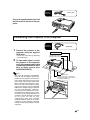
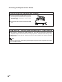
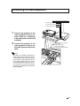
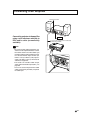
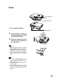
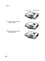
Connections and Setup
Connections and Setup
Connecting the Projector to Other Devices
Before Connecting
Note
! Before connecting, make sure the power cord of the projector from the AC outlet is unplugged, and that the
devices to be connected are turned off. After making all connections, turn on the projector and then the other
devices.
When connecting a computer, ensure that it is the last device to be turned on after all the connections are
made.
! Ensure that you have read the operation manuals of the devices to be connected before making connections.
This projector can be connected to:
A computer using:
■ An RGB cable and a computer audio cable (commercially available) (See page 17.)
■ A DIN-D-sub RS-232C adaptor and an RS-232C serial control
cable (commercially available) (See page 22.)
Component video or audio-visual equipment:
■ A VCR, Laser disc player or other audio-visual equipment
(See page 19.)
■ A DVD player or DTV* decoder (See page 20.)
*DTV is the umbrella term used to describe the new digital television
system in the United States.
An amplifier or audio components using:
■ An audio cable (commercially available) (See page 21.)
A monitor using:
■ An RGB cable (See page 23.)
■ A computer RGB cable (commercially available)
(See page 23.)
-16
Connecting the Power
Cord
Supplied
accessory
Power code
Plug in the supplied power cord into
the AC socket on the rear of the projector.
Connections and Setup
Connecting the Projector to a Computer
Connecting to a Computer
Using the RGB Cable
1
Connect the projector to the
computer using the supplied
RGB cable.
! Secure the connectors by tightening
the thumbscrews.
2
Supplied
accessory
RGB cable
Notebook computer
To RGB output terminal
To audio output terminal
To input audio signal, connect
the projector to the computer
using the computer audio cable
(commercially available or available as Sharp service part
QCNWGA038WJPZ).
Note
! See page 93 “Computer Compatibility
Chart” for a list of computer signals compatible with the projector. Use with computer signals other than those listed may
cause some of the functions not to work.
! When connecting the projector to a computer in this way, select “RGB” for “Signal
Type” in the “Picture” menu. See page 46.
! A Macintosh® adaptor may be required for
use with some Macintosh ® computers.
Contact your nearest Macintosh® Dealer.
! Depending on the computer you are using,
an image may not be projected unless the
computer’s external output port is switched
on. (e.g. Press “Fn” and “F5” keys
simultaneously when using a SHARP
notebook computer). Refer to the specific
instructions in your computer’s operation
manual to enable your computer’s external
output port.
1 RGB cable
2 Computer audio cable (commercially
available or available as Sharp service
part QCNWGA038WJPZ)
-17
Connecting the Projector to Other Devices
Connecting the thumbscrew cables
■ Connect the thumbscrew cable making sure that it
fits correctly into the terminal. Then, firmly secure
the connectors by tightening the screws on both
sides of the plug.
■ Do not remove the ferrite core attached to the RGB
cable.
Ferrite core
“Plug and Play” function (when connecting to a 15-pin terminal)
■ This projector is compatible with VESA-standard DDC 1/DDC 2B. The projector and a VESA DDC
compatible computer will communicate their setting requirements, allowing for quick and easy setup.
■ Before using the “Plug and Play” function, be sure to turn on the projector first and the connected
computer last.
Note
! The DDC “Plug and Play” function of this projector operates only when used in conjunction with a VESA
DDC compatible computer.
-18
Connecting to Video Equipment
Connecting to Video
Equipment Using an
S-video, a Composite
Video or an Audio Cable
1
2
To S-video output terminal
To video output terminal
To audio output terminal
Connections and Setup
Using an S-video, video, or audio cable, a VCR,
laser disc player or other audio-visual equipment can be connected to INPUT 3, INPUT 4
and AUDIO (L/R) input terminals.
VCR or other audio-visual equipment
Connect the projector to the
video equipment using an Svideo cable or a composite
video cable (both commercially
available).
Connect the projector to the
video equipment using an audio cable (commercially available).
2 Audio cable (commercially
available)
1 Composite video cable
(commercially available)
1 S-video cable (commercially available)
Note
! The INPUT 4 (S-VIDEO) terminal uses a
video signal system in which the picture
is separated into color and luminance signals to realize a higher-quality image. To
view a higher-quality image, use a commercially available S-video cable to connect the INPUT 4 terminal on the projector and the S-video output terminal on the
video equipment.
-19
Connecting the Projector to Other Devices
Connecting to
Component Video
Equipment
Use a 3 RCA to 15-pin D-sub cable when connecting to the INPUT 1 or 2 terminal, component video equipment such as DVD players
and DTV* decoders.
Optional
cable
3RCA to 15-pin D-sub cable
AN-C3CP2
(9'10" (3.0 m))
To analog component
output terminal
To audio output terminal
DVD player or
DTV* decoder
*DTV is the umbrella term used to describe
the new digital television system in the United
States.
1
2
Connect the projector to the
video equipment using the 3
RCA to 15-pin D-sub cable
(sold separately).
D-sub cable (sold separately)
2 ø3.5 mm stereo minijack to RCA audio cable
Connect the projector to the
video equipment using a ø3.5
mm stereo minijack to RCA audio cable (commercially available).
Note
! When connecting the projector to the
video equipment in this way, select “Component” for “Signal Type” in the “Picture”
menu. See page 46.
! A ø3.5 mm stereo minijack to RCA audio
cable (commercially available) is required
for audio input.
-20
1 3 RCA to 15-pin
(commercially available)
Connecting to an Amplifier
Connecting to an
Amplifier or Other Audio
Components
Audio input terminal
Connect the projector to theamplifier
using a ø3.5 mm stereo minijack to
RCA audio cable (commercially
available).
Connections and Setup
Using a ø3.5 mm stereo minijack to RCA audio cable, an amplifier or other audio components can be connected to the AUDIO OUTPUT terminal.
Amplifier
ø3.5 mm stereo minijack to RCA audio cable
(commercially available)
Info
! By using external audio components, the
volume can be amplified for better sound.
! The AUDIO OUTPUT terminal allows you
to output audio to audio components from
the selected AUDIO input terminal (for
INPUT 1 and 2) or AUDIO (L/R) input terminals (for INPUT 3 and 4) connected to
audiovisual equipment.
! For details on Variable Audio Output
(VAO) and Fixed Audio Output (FAO), see
page 63.
! A ø3.5 mm stereo minijack to RCA audio
cable (commercially available) is required
for audio input.
-21
Connecting the Projector to Other Devices
Controlling the Projector by a Computer
Connecting to a
Computer Using a DIND-sub RS-232C Adaptor
and an RS-232C Serial
Control Cable
When the RS-232C terminal on the projector
is connected to a computer with a DIN-D-sub
RS-232C adaptor and an RS-232C serial control cable (cross type, commercially available),
the computer can be used to control the projector and check the status of the projector.
See page 89 for details.
1
2
Connect the supplied DIN-Dsub RS-232C adaptor to an RS232C serial control cable (commercially available).
Supplied
accessory
Optional
cable
DIN-D-sub
RS-232C adaptor
RS-232C terminal
Desktop computer
DIN-D-sub
RS-232C adaptor
RS-232C serial control cable
(commercially available)
Use the above cables to connect the projector and the computer.
Note
! Do not connect or disconnect an RS-232C
serial control cable to or from the computer while it is on. This may damage your
computer.
! The RS-232C function may not operate if
your computer terminal is not correctly set
up. Refer to the operation manual of the
computer for details.
! See page 88 for connection of an RS232C serial control cable.
-22
XGC58X_C68X_E_PDF_p019_024.p65
22
05.6.9, 5:33 PM
Connecting to a Monitor
Watching Images on
Both the Projector and
a Monitor
1
2
Connect the projector to the
computer and monitor using
RGB cables (one is supplied, the
other is commercially available).
Optional
cable
RGB cable
To RGB input terminal
RGB cable
(commercially available)
Monitor
Desktop computer
RGB cable
(supplied)
To RGB output terminal
In the “Options(1)” menu, select “Economy Mode”, “Mntr.
out/RS232” and then “ON”.
(see page 69.)
Note
! Analog RGB signals as well as Component
signals can be output to the monitor.
Using as a Wired Remote Control
Connecting the Remote
Control to the Projector
When the remote control cannot be used due to
the range or positioning of the projector (rear projection, etc.), connect a ø3.5 mm stereo or mono
minijack cable (commercially available or available
as Sharp service part QCNWGA038WJPZ) from the
WIRED R/C JACK on the top of the remote control
to the WIRED REMOTE control input terminal.
Note
! FORWARD/BACK presentation control cannot be used when the remote control is wired
to the projector. To utilize this feature, disconnect the cable from the remote control.
WIRED REMOTE control input terminal
To WIRED R/C JACK
ø3.5 mm stereo or mono
minijack cable
(commercially available or
available as Sharp service
part QCNWGA038WJPZ)
-23
Connections and Setup
You can display computer images on both the
projector and a separate monitor using two
sets of an RGB cable. An RGB cable is supplied with this projector. You need to buy another RGB cable for connecting the projector
to a monitor.
Supplied
accessory
Connecting the Projector to Other Devices
Using the Wireless Presentation Function of the
Remote Control
The Wireless Presentation function on the projector works the same as the [Page Up] and
[Page Down] keys on a computer keyboard. It can also be used to move forward or backward
when viewing images of presentation software such as Microsoft® PowerPoint®.
Using the Wireless Presentation Function
1
Supplied
accessory
Connect the projector to the
computer using the supplied
USB cable.
USB cable
Computer
USB terminal
Note
! This function only works with the
Microsoft® Windows® OS and Mac®
OS. However, this function does not
work with the following operation
systems that do not support USB.
! Versions earlier than Windows ®
95.
! Versions earlier than Windows ®
NT4.0.
! Versions earlier than Mac® OS 8.5.
2
-24
Press
or
while using
presentation software on your
computer.
! Press
to move the page up.
! Press
to move the page down.
USB cable
BACK
button
FORWARD
button
Setup
Using the Adjustment
Feet
HEIGHT ADJUST
button
The height of the projector can be adjusted
using the adjustment feet at the front and back
of the projector when the surface the projector is placed on is uneven or when the screen
is slanted.
The projection of the image can be made
higher by adjusting the projector when it is in
a location lower than the screen.
Connections and Setup
1
Adjustment foot
Press HEIGHT ADJUST.
Adjustment feet
2
3
Lift the projector to adjust its
height and remove your finger
from HEIGHT ADJUST.
Rotate the adjustment feet at
the back of the projector for
fine adjustment.
Up
Down
Note
! When returning the projector to its original
position, hold the projector firmly, press
HEIGHT ADJUST and then gently lower it.
! The projector is adjustable up to approximately 12 degrees on the front and 3
degrees on the back from the standard position.
Info
! Do not press HEIGHT ADJUST when the
adjustment foot is extended without firmly
holding the projector.
! Do not hold the lens when lifting or lowering the projector.
! When lowering the projector, be careful
not to get your finger caught in the area
between the adjustment foot and the
projector.
-25
Setup
Adjusting the Lens
Focus ring
Zoom knob
The image is focused and adjusted to the
desired size using the focus ring or zoom
knob on the projector.
1
2
The focus is adjusted by rotating the focus ring.
Zooming is adjusted by moving the zoom knob.
ut
mo
Zoo
m in
Zoo
-26