1
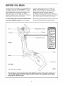
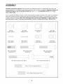
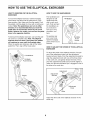
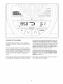
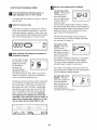
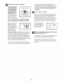
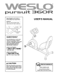
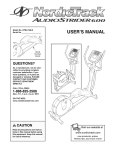
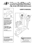
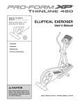
Model No. 831.28643.0
Serial No.
ELLIPTICAL
EXERCISER
User's Manual
Serial
Number
Decal
• Assembly
• Operation
• Maintenance
• Part List and Drawing
CAUTION
Read all precautions and instructions in this manual before using
this equipment. Keep this manual for future reference.
Sears, Roebuck and Co., Hoffman Estates, IL 60179
TABLE OF CONTENTS
IMPORTANT PRECAUTIONS
................................................................
BEFORE YOU BEGIN ......................................................................
ASSEMBLY ...............................................................................
HOW TO USE THE ELLIPTICAL EXERCISER ...................................................
MAINTENANCE AND TROUBLESHOOTING
...................................................
CONDITIONING GUIDELINES ...............................................................
PART LIST ..............................................................................
EXPLODED DRAWING ....................................................................
HOW TO ORDER REPLACEMENT PARTS .............................................
90 DAY FULL WARRANTY
..........................................................
2
3
4
8
15
16
17
18
Back Cover
Back Cover
IMPORTANT PRECAUTIONS
'_
WARNING:
To reduce the risk of serious injury, read the following
important precau-
tions before using the elliptical exerciser.
1. Read all instructions in this manual and all
warnings on the elliptical exerciser before
using the elliptical exerciser. Use the elliptical exercise only as described in this
manual.
7. The elliptical exerciser should not be used
by persons weighing more than 250 pounds.
8.
2. It is the responsibility of the owner to ensure
that all users of the elliptical exerciser are
adequately informed of all precautions.
9. Hold the handgrip pulse sensor or the handlebars when mounting, dismounting, or
sing the elliptical exerciser.
3. The elliptical exerciser is intended for
home use only. Do not use the elliptical
exerciser in a commercial, rental, or institutional setting.
4.
Wear appropriate exercise clothes when
using the elliptical exerciser. Always wear
athletic shoes for foot protection while exercising.
10. The pulse sensor is not a medical device.
Various factors may affect the accuracy of
heart rate readings. The pulse sensor is
intended only as an exercise aid in determining heart rate trends in general.
Keep the elliptical exerciser indoors, away
from moisture and dust. Place the elliptical
exerciser on a level surface, with a mat
beneath it to protect the floor or carpet.
Make sure that there is enough clearance
around the elliptical exerciser to mount, dismount, and use it.
11. Keep your back straight while using the elliptical exerciser; do not arch your back.
12. If you feel pain or dizziness while exercising,
stop immediately and cool down.
5. Inspect and properly tighten all parts regularly. Replace any worn parts immediately.
13. When you stop exercising, allow the pedals
to slowly come to a stop.
6. Keep children under 12 and pets away from
the elliptical exerciser at all times.
_
WARNING:
Before beginning this or any exercise program, consult your physician.
This is especially important for persons over the age of 35 or persons with pre-existing health problems. Read all instructions before using. Sears assumes no responsibility for personal injury or
property damage sustained by or through the use of this product.
2
BEFORE YOU BEGIN
Congratulations for selecting the new PROFORM ®XP
115 elliptical exerciser. The PROFORM XP 115 is an
incredibly smooth exerciser that moves your feet in a
natural elliptical path, minimizing the impact on your
knees and ankles. The unique XP 115 features
adjustable resistance and a state-of-the-art console to
help you get the most from your exercise.
tions after reading this manual, call 1-800-4-MYHOME _ (1-800-469-4663). To help us assist you,
please note the product model number and serial
number before calling. The model number is
831.28643.0. The serial number can be found on a
decal attached to the elliptical exerciser (see the front
cover of this manual for the location of the decal).
For your benefit, read this manual carefully before
you use the elliptical exerciser. If you have ques-
Before reading further, please familiarize yourself with
the parts that are labeled in the drawing below.
Fan
Handlebal
Handgrip Pulse Sensor
Console
=Misuse of this machine
may result in serious
injury.
• Read user's manua_
prior to use and follow
all warnings and
instructions.
• Do not allow children
on or around machine.
Water Bottle Holder*
, Pedals continue to
spin when you stop
pedaling.
=Spinning pedals can
cause injury.
FRONT
° Reduce pedal speed
in a controlledmanner.
, User weight must not
exceed 250 pounds.
• Replace label if
damaged, illegible, or
removed.
Pedal
Wheel
Pedal Disk
LEFT SIDE
*No water bottle is included
BACK
The decal shown above has been placed on the elliptical exerciser. If the decal is missing, or if
it is not legible, please call toll-free 1-888-533-1333 and order a free replacement decal. Apply
the decal in the location shown.
ASSEMBLY
Assembly requires two persons. Place all parts of the elliptical exerciser in a cleared area and remove the
packing materials. Do not dispose of the packing materials until assembly is completed. Assembly requires the
included hex keys as well as a phillips screwdriver _-__,
an adjustable wrench
and a rubber mallet _
............... 3 •
As you assemble the elliptical exerciser, use the drawings below to identify small parts. The number in parentheses
below each drawing is the key number of the part, from the PART LIST on page 17. The second number is the
quantity needed for assembly. Note: Some small parts may have been pre-assembled.
If a part is not in the
parts bag, check to see if it has been pre-assembled. If a part is missing, call toll-free 1-888-533-1333.
\
\.
M8 Split
Washer (100)-4
MIO Split
Washer (70)-2
Wave Washer
(95)-2
M8 Large
Washer (53)-10
M4 x 22mm
Screw (91)-2
M8 Nylon
Locknut (46)-8
M10 Nylon
Locknut (29)-4
=,
M4 x 16mm
Screw (66)-4
M8 x 25mm Patch
Screw (22)-2
M8 x 45mm Button
Bolt (50)-4
M8 x 65mm Button Screw (99)-4
M8 x 50mm Button
Screw (89)-4
M10 x 52mm Bolt Set (27)-2
4
Identify the Front Stabilizer (3). While another person
lifts the front of the Frame (1), attach the Front
Stabilizer to the Frame with two M10 x 112mm
1.
1
32
34
Carriage Bolts (34) and two M10 Nylon Locknuts (29).
Make sure that the Front Stabilizer is turned so the
Wheels (32) are not touching
the floor.
3
29
While another person lifts the back of the Frame (1),
attach the Rear Stabilizer (4) to the Frame with two
M10 x 112mm Carriage Bolts (34) and two M10 Nylon
Locknuts (29).
2,
.
29
While another person holds the Upright (2) in the position shown, connect the Upper Wire Harness (86) to
the Lower Wire Harness (87). Carefully pull the
upper end of the Upper Wire Harness to remove
any slack, While holding the upper end of the
Upper Wire Harness, insert the Upright into the
Frame (1). Do not pinch the Wire Harnesses.
Avoid pinching
or damaging the
wire harnesses
during this step.
Slide an M10 Split Washer (70) and a Frame Spacer
(83) onto each of the two M10 x 88mm Button Screws
(63). Insert the Button Screws into the Frame (1) and
the Upright (2). Make sure that the concave ends of
the Frame Spacers are facing the Frame. Do not
tighten the Button Screws yet.
Attach the Water Bottle Holder (105) to the Upright (2)
with two M4 x 22mm Screws (91).
4
86
70 83
4. The Console (5) requires four 1.5V "D" batteries (not
included); alkaline batteries are recommended.
Remove the battery cover from the Console. Next,
insert four batteries into the battery compartments.
Make sure that the batteries are oriented as shown
by the diagrams inside the battery compartments.
Then, replace the battery cover.
Battery
Cover
Batteries
5. WhileanotherpersonholdstheConsole(5)nearthe
Upright(2),connectthewireharnessontheConsole
to theUpperWireHarness(86).Inserttheexcess
wireharnessintothe Upright.Next,attachthe
Consoletothe UprightwithfourM4x 16mmScrews
(66).Be carefulto avoidpinchingthe wireharnesses.
66
86
Wire
Harness
6. Identify the Left Handlebar (9), which is marked with a
sticker. Insert the Left Handlebar into one of the
Handlebar Legs (79); make sure that the Handlebar
Leg is turned so the hexagonal holes are oriented as
indicated. Attach the Left Handlebar to the Handlebar
Leg with two M8 x 45mm Button Bolts (50) and two M8
Nylon Locknuts (46). Make sure that the Nylon
Locknuts are set inside the hexagonal holes. Do not
tighten the Button Bolts yet,
Apply a generous amount of the included grease to the
Pivot Axle (97) and to two M8 Large Washers (53). Next,
insert the Pivot Axle into the Upright (2) and center it.
Apply more grease to both ends of the Pivot Axle.
Grease
Slide a Handlebar Spacer (25) onto the short tube on the
Left Handlebar (9), and rotate the Handlebar Spacer so
the small arrow is pointing toward the floor. Next, slide the
Left Handlebar onto the left end of the Pivot Axle (97).
Finger tighten an M8 x 25mm Patch Screw (22) with an
M8 Large Washer (53) and a Wave Washer (95) into the
end of the Pivot Axle. Then, attach a Handlebar Cap (23)
by pressing its small tabs into the Handlebar Spacer.
23
53
2--_,_i
5o !
Hexagonal
Holes
Assemble the Right Handlebar (not shown) and the other
Handlebar Leg (not shown) in the same way.
Now, tighten both M8 x 25mm Patch Screws (22) at the
same time.
7. Apply a thin film of grease to the shaft of an
M10 x 52mm Bolt Set (27) and to the surfaces of the
two Leg Bushings (28) in the left Handlebar Leg (79).
Next, attach the left Handlebar Leg (79) to the Left
Pedal Arm (14) with the M10 x 52mm Bolt Set (27). Do
not overtighten the Bolt Set; the left Handlebar Leg
must be able to pivot freely.
Attach the right Handlebar Leg (79) to the Right Pedal
Arm (103) in the same way.
See step 3. Tighten the M10 x 88mm Button Screws
(63). See step 6. Tighten the M8 x 45mm Button
Bolts (50) in the Handlebar Legs (79),
6
103
27
14
8. Attach a Pedal Bracket (16) to the Left Pedal Arm (14)
with two M8 x 65mm Button Screws (99), two M8 Large
Washers (53), and two M8 Nylon Locknuts (46).
8
103
12
Identify the Left Pedal (13). Attach the Left Pedal to the
Left Pedal Arm (14) with two M8 x 50mm Button
Screws (89), two M8 Split Washers (100) and two M8
Large Washers (53).
Attach the other Pedal Bracket (not shown) and the
Right Pedal (12) to the Right Pedal Arm (103) in the
same way.
99
89
9. Make sure that all parts of the elliptical exerciser are properly tightened, Note: Some hardware may be
left over after assembly is completed. To protect the floor or carpet from damage, place a mat under the elliptical exerciser.
7
HOW TO USE THE ELLIPTICAL
HOW TO EXERCISE ON THE ELLIPTICAL
EXERCISER
EXERCISER
HOW TO USE THE HANDLEBARS
The handlebars are
To mount the elliptical exerciser, hold the handgrip
pulse sensor and step onto the pedal that is in the
lower position. Next, step onto the other pedal. Push
the pedals until they begin to move with a continuous
motion. Note: The pedal discs can turn in either
direction. It is recommended that you move the
pedal discs in the direction shown by the arrow
below; however, for variety, you can turn the pedal
discs in the opposite direction.
To dismount the elliptical exerciser, wait until the pedals come to a complete stop. Note: The elliptical
exerciser does not have a free wheel; the pedals
will continue to move until the flywheel stops.
When the pedals are stationary, step off the higher
pedal first. Then, step off the lower pedal.
"Handgrip
Pulse Sensor
Pedals
designed to add
upper-body exercise to your workouts. Push and pull
the handlebars as
you exercise to
work your arms,
shoulders, and
back.
Handlebars
To exercise only
your lower body,
hold the handgrip
pulse sensor as you
exercise.
HOW TO ADJUST THE STRIDE OF THE ELLIPTICAL
EXERCISER
To adjust the stride of the elliptical exerciser, first pull
one of the adjustment knobs until the adjustment
bracket will pivot freely. Pivot the adjustment bracket to
align the adjustment knob with one of the three holes
in the crank arm, and gently release the knob. Then,
pivot the adjustment bracket back and forth slightly to
make sure that the adjustment pin is engaged in one of
the holes in the crank arm.
Adjustment
Bracket
Adjustment
Pin
Crank
Pedal
Holes
Adjust the other side of the elliptical exerciser in the
same way.
PULSE CONTROL
PROGRAMS
........................
TIME
RESISTANCE
& RPM
PROGRAMS
RPM
RESISTANCE
FAN
PROGRAMS
FEATURES OF THE CONSOLE
each pulse control program automatically controls the
resistance of the pedals and prompts you to increase
or decrease your pedaling pace to keep your heart rate
near a target heart rate setting. Each resistance & rpm
program automatically changes the resistance of the
pedals and prompts you to vary your pedaling pace as
it guides you through an effective workout.
The advanced console offers an array of features
designed to make your workouts more effective and
enjoyable.
When the manual mode of the console is selected,
you can change the resistance of the pedals with the
touch of a button. As you exercise, the console will
provide continuous exercise feedback. You can even
monitor your heart rate using the handgrip pulse
sensor.
To use the manual mode of the console, follow the
steps beginning on page 10. To use a pulse control
program, see page 12. To use a resistance & rpm
program, see page 14.
The console also offers two pulse control programs and
four resistance & rpm programs. During your workout,
Note: If there is a sheet of clear plastic on the face of
the console, remove the plastic.
9
HOW TO USE THE MANUAL MODE
D
B
ress the
Resistance
button or
begin
pedaling
to turn decrease
on the console.
Select the manual mode,
Each time the console is turned on, the manual
mode will be selected automatically. If you have
previously selected a program, return to the manual mode by pressing the Programs button repeatedly until the display appears as shown below.
U 'LJ L.!
B
The left side of the display will also show your
heart rate when you use the handgrip pulse sensor (see step 5 on page 11).
The center of the
U
t=l
egin
pedaling
and change the resistance
the
pedals
as desired.
display--When the
manual mode is
of
I t",m
[_:>"
i "3
L_
_ _Q_
_
<::-J
"==""'=
_]
TOO
ml
an
,==,==,="
you exercise, indicators will appear in succession
around the track until the entire track appears.
The track will then disappear and the indicators
will again begin to appear in succession.
The center of the display will also show the resistance setting of the pedals for a few seconds each
time the resistance setting changes.
The right side of the
display--The right
side of the display will
show the distance
(total revolutions) you
have pedaled and
your pedaling pace
(revolutions per minute [rpm]).
During your workout, the Pace Coach will prompt
you to maintain a target pace of 50 revolutions
per minute (rpm). If you choose, increase your
pace when one of the "Too Stow" arrows lights
and decrease your pace when one of the "Too
Fast" arrows lights. When the center indicator
lights, maintain your current pace. Important:
The target pace is intended only to provide
motivation, Your actual pace may be slower or
faster than the target pace, Make sure to exercise at a pace that is comfortable
for you.
SLOW
_'="="='
selected, the center of
the display will show a
track that represents
640 revolutions. As
As you pedal, change
the resistance of the
pedals by pressing
the Resistance
increase and
decrease buttons
repeatedly. There are
ten resistance levels. Note: After you press the
buttons, it will take a moment for the pedals to
reach the selected resistance level.
TOO
with the display.
The left side of the
display--The
left side
of the display will
show the elapsed
time, the approximate
number of grams of
carbs you have
burned, and the approximate number of calories
you have burned. Note: When a preset program is
selected (except for pulse control program 2), the
display will show the time remaining in the program instead of the elapsed time.
A moment after the console is turned on, the display will light.
la
Monitor your progress
I|
FAST
£'3 "3
10
ol
E"
RPM
0
Measure your heart rate if desired.
If there are sheets
of clear plastic on
the metal contacts
I
I
ful not to move your hands excessively or to
squeeze the metal contacts too tightly. For optimal performance, clean the metal contacts using
a soft cloth; never use alcohol, abrasives, or
chemicals.
Metal Contacts
on the handgrip
pulse sensor, peel
off the plastic, To
measure your heart
rate, hold the handgrip pulse sensor,
with your palms resting on the metal contacts. Avoid moving your
hands or gripping the contacts too tightly.
r,t
Turn on the fan if desired.
To turn on the fan at low speed, press the Fan
button. To turn on the fan at high speed, press
the button a second time. To turn off the fan,
press the button a third time. Note: tf the pedals
are not moved for a few minutes, the fan will
automatically turn off to conserve the batteries.
Pivot the thumb tab
on the right side of
the fan to adjust the
angle of the fan.
When your pulse is
detected, a heartshaped
symbol
will
flash
in the
left side
-tgB
of the display each
PULSE
time your heart
beats, one or two
dashes will appear, and then your heart rate will
be shown. For the most accurate heart rate read-
B
ing, hold the contacts for at least 15 seconds.
Note: If you continue to hold the handgrip pulse
sensor, the display will show your heart rate for
up to 30 seconds. The display will then show your
heart rate along with the other modes.
Thumb
Tab
hen
you are finished
exercising, the console
will
automatically
turn off.
If the pedals are not moved for several seconds, a
tone will sound and the console will pause.
If the pedals are not moved for about five minutes, the console will turn off and the display will
be reset.
If your heart rate is not shown, make sure that
your hands are positioned as described. Be care-
11
If pulse control program 2 is selected, the target heart rate setting for the program will flash in
the display, tf desired, press the Resistance
increase and decrease buttons to change the target heart rate setting (see EXERCISE INTENSITY on page 16).
HOW TO USE A PULSE CONTROL PROGRAM
_1
Press
Resistance
button or
begin the
pedaling
to turn decrease
on the console.
A moment after the console is turned on, the display will light.
B
B
It is not necessary to hold the handgrip pulse
sensor continuously during a pulse control program; however, you should hold the handgrip
pulse sensor frequently for the program to operate properly. Each time you hold the handgrip
pulse sensor, keep your hands on the metal
contacts for at least 30 seconds.
Select one of the pulse control programs.
Press the Programs
button repeatedly
until "P 1" or "P 2"
appears in the right
side of the display.
If pulse control program 1 is selected,
a profile of the target
heart rate settings
for the program will
scroll across the
center of the display.
-.P
Hold the handgrip pulse sensor.
I
O
Begin pedaling
to start the program.
Pulse control program 1 is divided into 30 oneminute segments. One target heart rate setting is
programmed for each segment. Note: The same
target heart rate setting may be programmed for
two or more consecutive segments.
ID --P
mmmmllll_l
IIl_ilmll
r
The target heart rate
setting for the first
segment will be
shown in the flashing
Current Segment column in the center of
If pulse control program 2 is selected,
a pulse symbol will
appear in the center
of the display. Each
time a heartbeat is
detected while you
are using the handgrip pulse sensor, the pulse
symbol will reappear.
the display. The target
heart rate settings for the next four segments will
be shown in the columns to the right.
When only three seconds remain in the first segment of the program, both the Current Segment
column and the column to the right will flash, a
series of tones will sound, and all target heart
rate settings will move one column to the left.
The target heart rate setting for the second segment will then be shown in the flashing Current
Segment column.
Enter a target heart rate setting.
If pulse control program 1 is selected,
the maximum target
_
(( r'_
heart rate setting of
_
_ LJ
the program will
PULSE
flash in the display. If
desired, press the
Resistance increase and decrease buttons to
change the maximum target heart rate setting
(see EXERCISE INTENSITY on page 16). If you
change the maximum target heart rate setting,
the intensity level of the entire program will
change.
Pulse control program 2 is divided into 40 oneminute segments. The same target heart rate setting is programmed for all segments. Note: For a
shorter workout, stop exercising or select a different program before the program ends.
12
During both pulse control programs, the console will regularly compare your heart rate to the
target heart rate setting. If your heart rate is too
far below or above the target heart rate setting,
the resistance of the pedals will automatically
increase or decrease to bring your heart rate
closer to the target heart rate setting.
Note: During the program, you can manually override the resistance setting for the current segment, if desired, by pressing the increase and
decrease buttons. However, when the console
compares your heart rate to the target heart rate
setting, the resistance of the pedals may automatically increase or decrease to bring your heart
rate closer to the target heart rate setting.
After the first minute of the program, the Pace
Coach will prompt you to maintain a consistent
pedaling pace. When one of the "Too Slow"
arrows lights, increase your pace. When one of
the "Too Fast" arrows lights, decrease your pace.
When the center indicator lights, maintain your
current pace.
If you stop pedaling for several seconds, a tone
will sound and the program will pause. To restart
the program, simply resume pedaling.
0
Monitor your progress with the display.
See step 4 on page 10.
B
Turn on the fan if desired.
See step 6 on page 11.
When
you are finished
exercising, the console
will automatically
turn off.
Important: The target heart rate settings are
intended only to provide motivation. Your
actual heart rate may be slower than the target heart rate settings. Make sure to exercise
at a pace that is comfortable for you.
See step 7 on page 11.
13
HOW TO USE A RESISTANCE
B
Important: The pace settings are intended
only to provide motivation. Your actual pace
may be slower than the pace settings. Make
sure to exercise at a pace that is comfortable
for you.
& RPM PROGRAM
ress the
Resistance
button or
begin
pedaling
to turn decrease
on the console.
When only three seconds remain in the first segment of the program, both the Current Segment
column and the column to the right will flash, a
series of tones will sound, and all resistance settings will move one column to the left. The resistance setting for the second segment will then be
shown in the flashing Current Segment column,
and the resistance of the pedals will change to the
resistance setting for the second segment. Note: If
all of the indicators in the Current Segment column
are lit after the resistance settings have moved to
the left, the resistance settings may move downward so only the highest indicators appear in the
matrix.
A moment after the console is turned on, the display will light.
la
Select one of the resistance & rpm programs.
Press the Programs
button repeatedly until
"P 3," "P 4," "P 5," or
"P 6" appears in the
right side of the display. When a resistance & rpm program
is selected, a profile of the resistance settings of
the program will scroll across the center of the
display. The left side of the display will show how
long the program will last.
D
Begin pedaling
The program will continue until the resistance setting for the last segment is shown in the Current
Segment column and the last segment ends.
to start the program.
Each program is divided into several one-minute
segments. One resistance setting and one pace
setting are programmed for each segment. Note:
The same resistance setting and/or pace setting
may be programmed for two or more consecutive
segments.
Note: During the program, you can override the
resistance setting for the current segment, if
desired, by pressing the increase or decrease button. However, when the next segment begins, the
resistance will change if a different resistance setting is programmed for the next segment.
The resistance setting
Current Segment
for the first segment
will be shown in the
flashing Current
Segment column in
the center of the display. (Note: The pace
settings are not shown in the display.) The resistance settings for the next four segments will be
shown in the columns to the right.
If you stop pedaling for several seconds, a tone
will sound and the program will pause. To restart
the program, simply resume pedaling.
L.-.
B
onitor your progress
with the display.
See step 4 on page 10.
[_"."_Measure your heart rate if desired.
See step 5 on page 11.
As you exercise, the Pace Coach will prompt you
to keep your pedaling pace near the pace setting
for the current segment. When one of the "Too
Slow" arrows lights, increase your pace. When
one of the "Too Fast" arrows lights, decrease your
pace. When the center indicator lights, maintain
your current pace.
r_Turn
on the fan if desired.
See step 6 on page 11.
B
hen
you are finished
exercising, the console
will
automatically
turn off.
See step 7 on page 11.
14
MAINTENANCE
AND TROUBLESHOOTING
HANDGRIP PULSE SENSOR TROUBLESHOOTING
Inspect and tighten all parts of the elliptical exerciser
regularly. Replace any worn parts immediately.
• Avoid moving your hands while using the handgrip
pulse sensor. Excessive movement may interfere
with heart rate readings.
To clean the elliptical exerciser, use a damp cloth and
a small amount of mild soap. Important: To avoid
damaging the console, keep liquids away from the
console and keep the console out of direct sunlight.
• Do not hold the metal contacts too tightly; doing so
may interfere with heart rate readings.
BATTERY REPLACEMENT
• For the most accurate heart rate reading, hold the
metal contacts for about 30 seconds.
If the console displays become dim, the batteries
should be replaced; most console problems are the
result of low batteries. See assembly step 4 on page
5 for replacement instructions.
For optimal performance of the handgrip pulse sensor, keep the metal contacts clean. The contacts
can be cleaned with a soft cloth--never use alcohol,
abrasives, or chemicals.
HOW TO LEVEL THE ELLIPTICAL EXERCISER
After moving the
elliptical exerciser to the location
- , _._&?_,_-_ _,--. --_.
where it will be
used, make sure
that the ends of
both stabilizers
are touching the
Leveil ng Foot
",_
floor. If the elliptical exerciser
rocks slightly
during use, turn one or both of the leveling feet under
the front stabilizer until the rocking motion is eliminated.
15
CONDITIONING
GUIDELINES
During the first few minutes of exercise, your body
uses easily accessible carbohydrate calories for energy. Only after the first few minutes of exercise does
your body begin to use stored fat calories for energy.
If your goal is to burn fat, adjust the intensity of your
exercise until your heart rate is near the lowest number in your training zone as you exercise.
_WARNING:
Before beginning th is or any exercise program, consult your physician. This is especially important for persons over the age of 35
or persons with pre-existing health problems.
The pulse sensor is not a medical device.
Various factors may affect the accuracy of
heart rate readings. The pulse sensor is
intended only as an exercise aid in determining heart rate trends in general.
For maximum fat burning, adjust the intensity of your
exercise until your heart rate is near the middle number in your training zone as you exercise.
Aerobic Exercise
If your goal is to strengthen your cardiovascular system, your exercise must be "aerobic." Aerobic exercise is activity that requires large amounts of oxygen
for prolonged periods of time. This increases the
demand on the heart to pump blood to the muscles,
and on the lungs to oxygenate the blood. For aerobic
exercise, adjust the intensity of your exercise until
your heart rate is near the highest number in your
training zone as you exercise.
The following guidelines will help you to plan your
exercise program. Remember that proper nutrition
and adequate rest are essential for successful results.
EXERCISE INTENSITY
Whether your goat is to burn fat or to strengthen your
cardiovascular system, the key to achieving the
desired results is to exercise with the proper intensity.
The proper intensity level can be found by using your
heart rate as a guide. The chart below shows recommended heart rates for fat burning, maximum fat
burning, and cardiovascular (aerobic) exercise.
165
155
145
140
130 125
115
_
145 138
130
125
118 110
103
C,_?
125
120
115
110
105
95
90
20
30
40
50
60
70
80
WORKOUT
GUIDELINES
Each workout should include the following three parts:
A warm-up, consisting of 5 to 10 minutes of stretching
and light exercise. A proper warm-up increases your
body temperature, heart rate, and circulation in preparation for exercise.
Training zone exercise, consisting of 20 to 30 minutes of exercising with your heart rate in your training
zone. Note: During the first few weeks of your exercise program, do not keep your heart rate in your
training zone for longer than 20 minutes.
To find the proper heart rate for you, first find your age
at the bottom of the chart (ages are rounded off to the
nearest ten years). Next, find the three numbers above
your age. The three numbers are your "training zone."
The lower two numbers are recommended heart rates
for fat burning; the highest number is the recommended heart rate for aerobic exercise.
A cool-down, with 5 to 10 minutes of stretching. This
will increase the flexibility of your muscles and will
help to prevent post-exercise problems.
EXERCISE FREQUENCY
To maintain or improve your condition, complete three
workouts each week, with at least one day of rest
between workouts. After a few months of regular exercise, you may complete up to five workouts each week
if desired. The key to success is to make exercise a
regular and enjoyable part of your everyday life.
Fat Burning
To burn fat effectively, you must exercise at a relatively low intensity level for a sustained period of time.
16
PART LIST--Model
Key No.
Qty.
1
2
3
4
5
6
7
8
9
10
11
12
13
14
15
16
17
18
19
20
21
22
23
24
25
26
27
28
29
30
31
32
33
34
35
36
37
38
39
40
41
42
43
44
45
46
47
48
49
50
51
52
53
54
1
1
1
1
1
1
1
2
1
1
2
1
1
1
2
2
2
4
2
2
2
2
2
6
2
2
2
4
4
1
1
2
2
4
2
1
1
1
1
2
1
2
1
1
2
11
2
2
1
4
4
1
10
1
No. 831.28643.0
Description
ROBO6A
Key No.
Qty.
55
56
57
58
59
60
61
62
63
64
65
66
67
68
69
70
71
72
73
74
75
76
77
78
79
80
81
82
83
84
85
86
87
88
89
90
91
92
93
94
95
96
97
98
99
100
101
102
103
104
105
#
#
#
1
1
2
4
4
4
4
4
2
2
2
6
4
1
1
2
2
2
1
8
2
1
1
1
2
1
1
8
2
4
1
1
1
2
4
4
2
2
3
4
2
2
1
8
4
4
4
2
1
2
1
2
1
1
Frame
Upright
Front Stabilizer
Rear Stabilizer
Console
Left Side Shield
Right Side Shield
Pedal Disc
Left Handlebar
Right Handlebar
Foam Grip
Right Pedal
Left Pedal
Left Pedal Arm
Pin Spacer
Pedal Bracket
Adjustment Pin
Pedal Arm Bushing
Adjustment Spring
Adjustment Bracket
Snap Ring
M8 x 25mm Patch Screw
Handlebar Cap
Handlebar Bushing
Handlebar Spacer
Upright Spacer
MIO x 52mm Bolt Set
Leg Bushing
MIO Nylon Locknut
Upright Bushing
Left Front Endcap
Wheel
M6 x 72mm Button Screw
M10 x 112mm Carriage Bolt
Rear Stabilizer Endcap
Left Crank Arm
Pulley
Right Crank Arm
Crank
Crank Bearing
Flywheel
Flywheel Bearing
Magnet
Flywheel Axle
Adjustment Knob
M8 Nylon Locknut
Crank Screw
Hub Cover
M6 x 25mm Bolt
M8 x 45mm Button Bolt
M6 x 18mm Button Bolt
"C" Magnet Bracket
M8 Large Washer
"C" Magnet
Description
Motor
Belt
Hub
Hub Spacer
M6 Nylon Locknut
M6 Nut
M5 Nylon Locknut
M5 x 12mm Bolt
MIO x 88mm Button Screw
M4 x 6mm Self-tapping Screw
Adjustment Bracket Screw
M4 x 16mm Screw
M4 x 25mm Screw
Right Front Endcap
Reed Switch Clamp
M10 Split Washer
Handlebar Endcap
Leveling Foot
M5 x 16mm Screw
M4 x 19mm Screw
M6 Eyebolt
Resistance Spring
Reed Switch
Reed Switch Bracket
Handlebar Leg
Side Shield Cover
"U" Bracket
Cover Screw
Frame Spacer
M4 x 12mm Round Head Screw
Resistance Cable
Upper Wire Harness
Lower Wire Harness
Pedal Arm Sleeve
M8 x 50mm Button Screw
Motor Washer
M4 x 22mm Screw
Inner Pedal Arm Sleeve
M6 Washer
Large Snap Ring
Wave Washer
M3 x 16mm Screw
Pivot Axle
M8 Jam Nut
M8 x 65mm Button Screw
M8 Split Washer
M8 x 45mm Button Screw
Pin Collar
Right Pedal Arm
M8 Washer
Water Bottle Holder
Hex Key
Grease
User's Manual
Note: "#" indicates a non-illustrated part. Specifications are subject to change without notice. If a part is missing, call toll-free 1-888-533-1333. See the back cover of this manual for information about replacement parts.
17
I"11
X
I'--
0
'_10
I"11
80
71
74
i
Q
24
I
24
97
74
L79
105
!
22
59
951
25
2_
51
/ 74
Z
0
27
23
28
i ,
67
27
I I
0')
4_
86
87
b
L_
_I _I
i
27
33
o
o0
o
o_
Ill
X
33
41
42
48 82
32
S
I"11
43
14 60
31
21 57
4O
39
63
!::I:1
101
I
29
¢0
47
13
53
m
58
46
98
Z
0
57
_4 45
82
34
48
103
92
4_
99
33
o
o0
o
o_
Your Home
For repair--in
or heating
your home--of
all major brand appliances, lawn and garden equipment,
and cooling systems, no matter who made it, no matter who sold it!
For the replacement
parts, accessories,
and user's manuals that you need to do-it-yourself.
For Sears professional
installation of home appliances
and items like garage door openers and water heaters.
1-800-4-MY-HOME
® (1-800-469-4663)
Call anytime, day or night (U.S.A. and Canada)
www.sears.com
www.sears.ca
Our Home
For repair of carry-in items like vacuums, lawn equipment,
and electronics, call or go on-line for the location of your nearest
Sears Parts & Repair Center.
1-800-488-1222
Call anytime, day or night (U.S.A. only)
www.sears.com
To purchase a protection agreement (U.S.A.)
or maintenance agreement (Canada) on a product serviced by Sears:
1-800-827-6655
(U.S.A.)
1-800-361-6665
(Canada)
Para pedir servicio de reparaci6n a domicilio, y para ordenar piezas:
1-888-SU-HOGAR
®(1-888-784-6427)
Sears
® Registered Trademark / TMTrademark / SMService Mark of Sears Brands, LLC
® Marca Registrada / TMMarca de Fabrica / SMMarca de Servicio de Sears Brands, LLC
f
90 DAY FULL WARRANTY
f
If this Sears Elliptical Exerciser fails due to a defect in material or workmanship within 90 days of the
date of purchase, call 1-800-4-MY-HOME ®(1-800-469-4663) to arrange for free repair (or replacement
if repair proves impossible). The frame is warranted for 5 years.
This warranty does not apply when the Elliptical Exerciser is used commercially or for rental purposes.
This warranty gives you specific legal rights, and you may also have other rights which vary from state
to state.
Sears, Roebuck
and Co., Hoffman
Estates, IL 60179
J
J
Part No. 238951 R0806A
Printed in China © 2006 ICON IP, Inc.