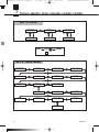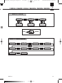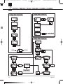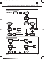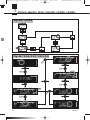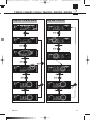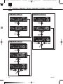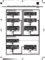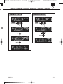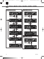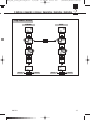
1
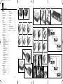
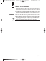
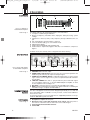
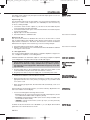
Umschlag_Klappe_grasl
01.03.2007
9:54 Uhr
Seite 2
Mikrofone · Kopfhörer · Drahtlosmikrofone · Drahtloskopfhörer · Kopfsprechgarnituren · Akustische Komponenten
Microphones · Headphones · Wireless Microphones · Wireless Headphones · Headsets · Electroacoustical Components
Microphones · Casques HiFi · Microphones sans fil · Casques sans fil · Micros-casques · Composants acoustiques
Microfoni · Cuffie HiFi · Microfoni senza filo · Cuffie senza filo · Cuffie-microfono · Componenti acustici
Micrófonos · Auriculares · Micrófonos inalámbricos · Auriculares inalámbricos · Auriculares con micrófono · Componentes acústicos
Microfones · Fones de ouvido · Microfones s/fios · Fones de ouvido s/fios · Microfones de cabeça · Componentes acústicos
AKG Acoustics GmbH
Lemböckgasse 21–25, A-1230 Vienna/AUSTRIA, phone: (+43-1) 86654-0*
e-mail: [email protected]
AKG Acoustics, U.S.
8500 Balboa Boulevard, Northridge, CA 91329, U.S.A, phone: (+1 818) 920-3212
e-mail: [email protected]
For other products and distributors worldwide visit www.akg.com
IVM 4
BEDIENUNGSANLEITUNG
. . . . . . . . . .
Bitte vor Inbetriebnahme des Gerätes lesen!
USER INSTRUCTIONS
. . . . . . . . . . . . . . .
Please read the manual before using the equipment!
MODE D’EMPLOI
. . . . . . . . . . . . . . . . . . . . .
Veuillez lire cette notice avant d’utiliser le système!
S. 2
p. 22
p. 42
ISTRUZIONI PER L’USO . . . . . . . . . . . . . p. 62
Prima di utilizzare l’apparecchio, leggere il manuale!
MODO DE EMPLEO . . . . . . . . . . . . . . . . . . . p. 82
Technische Änderungen vorbehalten. Specifications subject to change without notice. Ces caractéristiques sont susceptibles de modifications.
Ci riserviamo il diritto di effettuare modifiche tecniche. Nos reservamos el derecho de introducir modificaciones técnicas. Especificações sujeitas
a mudanças sem aviso prévio.
Printed in Austria on recycled paper.
03/07/9100 U 1229
¡Sirvase leer el manual antes de utilizar el equipo!
INSTRUÇÕES DE USO
. . . . . . . . . . . . . . .
Favor leia este manual antes de usar o equipamento!
S. 102
Umschlag_Klappe_grasl
01.03.2007
9:54 Uhr
Seite 1
Fig. 7
Inhaltsverzeichnis
Seite
Kurzanleitung . . . . . . . . . . . . . . . . . . . . . . . . . . . . . . 3
Symbole und Zeichensätze . . . . . . . . . . . . . . . . . . . 4
1 Sicherheit und Umwelt . . . . . . . . . . . . . . . . . . . . . 5
1.1 Sicherheit. . . . . . . . . . . . . . . . . . . . . . . . . . . . . 5
1.2 Hohe Lautstärke . . . . . . . . . . . . . . . . . . . . . . . 5
1.3 Umwelt. . . . . . . . . . . . . . . . . . . . . . . . . . . . . . . 6
2 Beschreibung . . . . . . . . . . . . . . . . . . . . . . . . . . . . . 7
2.1 Einleitung . . . . . . . . . . . . . . . . . . . . . . . . . . . . . 7
2.2 Lieferumfang . . . . . . . . . . . . . . . . . . . . . . . . . . 7
2.3 Optionales Zubehör . . . . . . . . . . . . . . . . . . . . . 7
2.4 Stationärer Stereo Sender SST 4 . . . . . . . . . . . 7
2.4.1 Frontplatte . . . . . . . . . . . . . . . . . . . . . . . 7
2.4.2 Display . . . . . . . . . . . . . . . . . . . . . . . . . . 8
2.4.3 Rückseite . . . . . . . . . . . . . . . . . . . . . . . . 8
2.5 Stereo Taschenempfänger SPR 4 . . . . . . . . . . 8
2.5.1 Bedienelemente . . . . . . . . . . . . . . . . . . . 8
2.5.2 Display . . . . . . . . . . . . . . . . . . . . . . . . . . 9
2.6 Ohrhörer IP 2 . . . . . . . . . . . . . . . . . . . . . . . . . . 9
1_2
2
Seite
5 Reinigung . . . . . . . . . . . . . . . . . . . . . . . . . . . . . . . 19
5.1 Sender und Empfänger . . . . . . . . . . . . . . . . . 19
5.2 Ohrhörer. . . . . . . . . . . . . . . . . . . . . . . . . . . . . 19
3_4_5
�
7 Technische Daten. . . . . . . . . . . . . . . . . . . . . . . . . 21
7.1 IVM 4 . . . . . . . . . . . . . . . . . . . . . . . . . . . . . . . 21
7.2 Sender SST 4 . . . . . . . . . . . . . . . . . . . . . . . . . 21
7.3 Empfänger SPR 4 . . . . . . . . . . . . . . . . . . . . . 21
7.4 Ohrhörer IP 2 . . . . . . . . . . . . . . . . . . . . . . . . . 21
7.5 Normen . . . . . . . . . . . . . . . . . . . . . . . . . . . . . 21
�
�
�
�
�
6 Fehlerbehebung . . . . . . . . . . . . . . . . . . . . . . . . . . 19
�
�
�
�
�
2
8_9
�
�
�
�
Fig. 13
1a
2
2a
2b
3
Fig. 7 bis 14 . . . . . . . . . . . . . . . . . . . . . Ausklappseiten
3
4
5
3
�
3a
Fig. 14
Fig. 12
�
1
2a
Fig. 9
1_2
�
�
�
�
�
4 Erweiterte Funktionen . . . . . . . . . . . . . . . . . . . . . 16
4.1 Sender . . . . . . . . . . . . . . . . . . . . . . . . . . . . . . 16
4.1.1 SOUND . . . . . . . . . . . . . . . . . . . . . . . . . 16
4.1.2 EXTRA. . . . . . . . . . . . . . . . . . . . . . . . . . 17
4.2 Empfänger . . . . . . . . . . . . . . . . . . . . . . . . . . . 17
4.2.1 Störfrequenzen suchen. . . . . . . . . . . . . 17
4.2.2 Squelch einstellen. . . . . . . . . . . . . . . . . 18
4.2.3 Gehörschutz-Limiter . . . . . . . . . . . . . . . 18
4.2.4 Balance . . . . . . . . . . . . . . . . . . . . . . . . . 18
4.2.5 Info . . . . . . . . . . . . . . . . . . . . . . . . . . . . 19
4
2b
�
AKG IVM 4
2c 2c
2d
�
�
�
Fig. 11
1
�
�
�
2a
�
�
�
�
Fig. 8
1
6_7
�
�
8 Anhang . . . . . . . . . . . . . . . . . . . . . . . . . . . . . . . . 122
Sender- und Empfängermenüs . . . . . . . . . . . . . 122
Grundfunktionen (Fig. A1 bis A8) . . . . . . . . . . . . 124
Erweiterte Funktionen (Fig. A9 bis A26) . . . . . . . 128
3 Inbetriebnahme . . . . . . . . . . . . . . . . . . . . . . . . . . 10
3.1 Farbcode austauschen . . . . . . . . . . . . . . . . . 10
3.1.1 Sender . . . . . . . . . . . . . . . . . . . . . . . . . 10
3.1.2 Empfänger . . . . . . . . . . . . . . . . . . . . . . 10
3.2 Sender positionieren . . . . . . . . . . . . . . . . . . . 10
3.3 Rackmontage des Senders . . . . . . . . . . . . . . 10
3.3.1 Einen Sender montieren . . . . . . . . . . . . 10
3.3.2 Zwei Sender nebeneinander montieren 10
3.4 Empfänger in Betrieb nehmen . . . . . . . . . . . . 11
3.4.1 Batterien einlegen . . . . . . . . . . . . . . . . . 11
3.4.2 Einschalten (LOCK/SETUP-Modus) . . . 11
3.4.3 Ausschalten . . . . . . . . . . . . . . . . . . . . . 11
3.4.4 Land wählen . . . . . . . . . . . . . . . . . . . . . 11
3.4.5 Frequenz automatisch wählen . . . . . . . 12
3.4.6 Frequenz manuell wählen . . . . . . . . . . . 12
3.4.7 Ohrhörer anschließen . . . . . . . . . . . . . . 12
3.5 Sender in Betrieb nehmen . . . . . . . . . . . . . . . 12
3.5.1 Antenne. . . . . . . . . . . . . . . . . . . . . . . . . 12
3.5.2 Audioverbindungen. . . . . . . . . . . . . . . . 12
3.5.3 Sender an das Netz anschließen. . . . . . 13
3.5.4 Einschalten (LOCK/ SETUP-Modus) . . . 13
3.5.5 Ausschalten . . . . . . . . . . . . . . . . . . . . . 14
3.5.6 Land wählen . . . . . . . . . . . . . . . . . . . . . 14
3.5.7 Frequenz einstellen (Preset-Menü) . . . . 14
3.5.8 Frequenz direkt einstellen . . . . . . . . . . . 14
3.5.9 Sendeleistung einstellen . . . . . . . . . . . . 14
3.5.10 Sender benennen . . . . . . . . . . . . . . . . 15
3.5.11 Eingangspegel einstellen . . . . . . . . . . 15
3.6 Mehrkanalanlagen . . . . . . . . . . . . . . . . . . . . . 15
2
Fig. 10
1
3_4
IVM4_Hex_final_XP7:Layout 1
2/27/07
11:25 AM
Seite 22
(Schwarz/Black Auszug)
Table of Contents
Page
FCC Statement.........................................................22
Getting Started Quickly ...........................................23
Symbols and Characters .........................................24
1 Safety and Environment .......................................25
1.1 Safety..............................................................25
1.2 High Volume....................................................25
1.3 Environment....................................................26
Page
4.2.1 Finding Interference Frequencies...........37
4.2.2 Setting the Squelch Threshold ...............38
4.2.3 Hearing Protection Limiter .....................38
4.2.4 Balance ..................................................38
4.2.5 Info .........................................................39
5 Cleaning.................................................................39
5.1 Transmitter and Receiver ................................39
5.2 Earbuds ..........................................................39
6 Troubleshooting ....................................................39
2 Description ............................................................27
2.1 Introduction ....................................................27
2.2 Unpacking ......................................................27
2.3 Optional Accessories......................................27
2.4 SST 4 Stationary Transmitter ..........................27
2.4.1 Front Panel.............................................27
2.4.2 Display ...................................................28
2.4.3 Rear Panel..............................................28
2.5 SPR 4 Stereo Bodypack Receiver ..................28
2.5.1 Controls .................................................28
2.5.2 Display ...................................................29
2.6 IP 2 Earbuds....................................................29
7 Specifications........................................................41
7.1 IVM 4...............................................................41
7.2 SST 4 Transmitter ...........................................41
7.3 SPR 4 Receiver ...............................................41
7.4 IP 2 Earbuds....................................................41
7.5 Standards .......................................................41
8 Appendix..............................................................122
Transmitter and Receiver Menus .........................122
Basic Functions (Figs. A1 to A8) ..........................124
Advanced Functions (Figs. A9 to A26).................128
3 Setting Up ..............................................................30
3.1 Color Coding...................................................30
3.1.1 Transmitter .............................................30
3.1.2 Receiver .................................................30
3.2 Placing the Transmitter ...................................30
3.3 Rack Mounting the Transmitter .......................30
3.3.1 Rack Mounting a Single Transmitter ......30
3.3.2 Rack Mounting Two Transmitters
Side by Side ...........................................30
3.4 Setting Up the Receiver ..................................31
3.4.1 Inserting Batteries ..................................31
3.4.2 Powering Up (LOCK/SETUP Modes) .....31
3.4.3 Powering Down......................................31
3.4.4 Selecting the Country Preset .................31
3.4.5 Automatic Frequency Selection .............32
3.4.6 Manual Frequency Selection..................32
3.4.7 Connecting Earbuds ..............................32
3.5 Setting Up the Transmitter ..............................32
3.5.1 Antenna..................................................32
3.5.2 Audio Connections ................................32
3.5.3 Connecting to Power .............................33
3.5.4 Powering Up (LOCK/SETUP Modes) .....33
3.5.5 Powering Down......................................34
3.5.6 Selecting the Country Preset .................34
3.5.7 Selecting Frequencies
from the Preset Screen...........................34
3.5.8 Selecting Frequencies
from the Frequency Screen ....................34
3.5.9 Setting RF Output ..................................34
3.5.10 Naming the Transmitter........................34
3.5.11 Setting Input Gain ................................34
3.6 Multichannel Systems.....................................35
Figs. 7 to 14 ...........................................Foldout Pages
4 Advanced Functions .............................................36
4.1 Transmitter......................................................36
4.1.1 SOUND ..................................................36
4.1.2 EXTRA....................................................37
4.2 Receiver..........................................................37
This device complies with Part 15 of the FCC Rules. Operation is subject to the following two conditions: (1) this
device may not cause harmful interference, and (2) this
device must accept any interference received, including
interference that may cause undesired operation.
22
FCC Statement
This equipment has been tested and found to comply
with the limits for a Class B digital device, pursuant to
Parts 74 and 15 of the FCC Rules. These limits are designed to provide reasonable protection against harmful
interference in a residential installation. This equipment generates, uses, and can radiate radio frequency
energy and, if not installed and used in accordance with
the instructions, may cause harmful interference to radio
communications. However, there is no guarantee that
interference will not occur in a particular installation. If
this equipment does cause harmful interference to radio
or television reception, which can be determined by
turning the equipment off and on, the user is encouraged to try to correct the interference by one or more of
the following measures:
• Reorient or relocate the receiving antenna.
• Increase the separation between the equipment and
the receiver.
• Connect the equipment into an outlet on a circuit different from that to which the receiver is connected.
• Consult the dealer or an experienced radio/TV technician for help.
Shielded cables and I/O cords must be used for this
equipment to comply with the relevant FCC regulations.
Changes or modifications not expressly approved in
writing by AKG Acoustics may void the user’s authority
to operate this equipment.
AKG IVM 4
IVM4_Hex_final_XP7:Layout 1
2/28/07
10:31 AM
Seite 23
(Schwarz/Black Auszug)
Getting Started Quickly
1
2
3
4
7
12
1.
2.
3.
4.
5.
Make all audio connections.
Connect the antenna to the transmitter.
Connect the transmitter to power.
Insert the supplied batteries into the SPR 4 receiver.
Switch power to the receiver on and select the code for the country where you
are going to operate your IVM 4 (section 3.4.4).
6. Select a clean frequency on the receiver ("AUTO" menu, section 3.4.5).
7. Connect the earbuds to the receiver.
8. Switch power to the transmitter on (section 3.5.4) and select the code for the
country where you are going to operate your IVM 4 (section 3.5.6).
9. Tune the transmitter to the same frequency you selected on the receiver (section 3.5.7).
10. Set RF output on the transmitter (section 3.5.9).
11. Set input gain on the transmitter (section 3.5.11).
12. Set the desired volume for the earbuds.
AKG IVM 4
23
IVM4_Hex_final_XP7:Layout 1
2/27/07
11:25 AM
Seite 24
(Schwarz/Black Auszug)
Symbols and Characters
Symbols Used
in the Manual
The following symbols are used in the menu diagrams Figs. A1 through A26 on
pages 121 to 136:
SETUP control
on SST 4 transmitter
2s
2s
Jog switch on SPR 4
receiver
Long push
(appropx. 2 secs.)
Short push
Turn all the way CW or
CCW
Turn all the way CCW
Turn all the way CW
Display Characters
24
SST 4 SPR 4
SST 4 SPR 4
SST 4 SPR 4
SST 4 SPR 4
Flashing character
AKG IVM 4
IVM4_Hex_final_XP7:Layout 1
2/27/07
11:25 AM
Seite 25
1 Safety and Environment
1. Do not spill any liquids on the equipment and do not drop any objects through
the ventilation slots in the equipment.
2. The equipment may be used in dry rooms only.
3. The equipment may be opened, serviced, and repaired by authorized personnel only. The equipment contains no user-serviceable parts.
4. Before connecting the equipment to power, check that the AC mains voltage
stated on the supplied power supply is identical to the AC mains voltage available where you will use the equipment.
5. Operate the equipment with the included power supply with an output voltage
of 12 VDC only. Using adapters with an AC output and/or a different output voltage may cause serious damage to the unit.
6. If any solid object or liquid penetrates into the equipment, shut down the sound
system immediately. Disconnect the power supply from the power outlet immediately and have the equipment checked by AKG service personnel.
7. If you will not use the equipment for a long period of time, disconnect the power
supply from the power outlet. Please note that the equipment will not be fully
isolated from power when you set the power switch to OFF.
8. Do not place the equipment near heat sources such as radiators, heating ducts,
or amplifiers, etc. and do not expose it to direct sunlight, excessive dust, moisture, rain, mechanical vibrations, or shock.
9. To avoid hum or interference, route all audio lines, particularly those connected
to the microphone inputs, away from power lines of any type. If you use cable
ducts, be sure to use separate ducts for the audio lines.
10. Clean the equipment with a moistened (not wet) cloth only. Be sure to disconnect the power supply cable from the power outlet before cleaning the equipment! Never use caustic or scouring cleaners or cleaning agents containing
alcohol or solvents since these may damage the enamel and plastic parts.
11. Use the equipment for the applications described in this manual only. AKG cannot accept any liability for damages resulting from improper handling or misuse.
12. In some countries, you may need a permit for operating your equipment. Be
sure to contact the respective authority of the country where you are going to
operate your equipment.
13. Any modifications made to the equipment without the express consent of AKG
may lead to violations of telecommunications legislation voicing the operating
permit.
Listening over headphones at excessive sound pressure levels, particularly
over extended periods of time, may damage your hearing! Therefore, always
set the volume as low as possible.
(Schwarz/Black Auszug)
!
L
1.1 Safety
!
L
1.2 High Volume
Important!
Table 1 is based on German research in occupational medicine and lists maximum
exposure times for high volume levels before hearing damage occurs. Please note
that local legislation where you will use your equipment may differ from the values
in Table 1. Basically, you can double the maximum exposure time without damaging your ears by reducing the sound pressure level by 3 dB.
Sound pressure
Maximum exposure
85 dB(A)
8 hours
88 dB(A)
4 hours
91 dB(A)
2 hours
94 dB(A)
1 hour
97 dB(A)
30 minutes
100 dB(A)
15 minutes
120 dB (A)
Threshold of pain
Table 1: Maximum exposure to sound pressure
levels
To protect your ears from damage, follow a few tips:
1. Set the volume just high enough to hear properly.
AKG IVM 4
25
IVM4_Hex_final_XP7:Layout 1
!
L
2/27/07
11:25 AM
Seite 26
(Schwarz/Black Auszug)
1 Safety and Environment
2. If you hear ringing or whistling sounds in your ears, fail to hear high notes (even
momentarily), or hear less clearly for a while after a concert, you have been exposed to excessive sound pressure levels for too long. Consult an audiologist
and use lower volume levels.
3. Have your ears checked by an audiologist on a regular basis.
4. To avoid infections, wipe the ear molds with a skin compatible antiseptic before
and after use. Stop using the earbuds if they are causing great discomfort or infection.
1.3 Environment
26
1. The power supply will draw a small amount of current even when the equipment is switched off. To save energy, disconnect the power cable from the
power outlet if you will leave the equipment unused for a long period of time.
2. When scrapping the equipment, separate the case, circuit boards, and cables,
and dispose of all components in accordance with local waste disposal rules.
3. The packaging of the equipment is recyclabe. Dispose of the packaging in an
appropriate container provided by the local waste collection/recycling entity and
observe all local legislation relating to waste disposal and recycling.
AKG IVM 4
IVM4_Hex_final_XP7:Layout 1
2/27/07
11:25 AM
Seite 27
(Schwarz/Black Auszug)
2 Description
Thank you for purchasing an AKG product. This Manual contains important instructions for setting up and operating your equipment. Please take a few minutes
to read the instructions below carefully before operating the equipment. Please
keep the Manual for future reference. Have fun and impress your audience!
2.1 Introduction
•
•
•
•
•
•
•
•
1 SST 4 stereo transmitter
1 SPR 4 bodypack stereo receiver
1 pair of IP 2 earbuds with 3 pairs of ear molds
1 rod antenna
1 rack mounting kit
1 power supply
2 AA size dry batteries
1 12-pc. color coding kit
2.2 Unpacking
•
Check that the packaging contains all of the items listed above. Should any of
these items be missing, please contact your AKG dealer.
•
•
•
•
•
•
•
•
•
•
SPC 4 wideband antenna combiner
SRA 2 W passive wideband directional antenna
RA 4000 W passive wideband omnidirectional antenna
HPA 4000 headphone amplifier
PSU 4000 central power supply
HUB 4000 Q network interface
MK PS antenna cables
Front panel mounting kit for supplied antenna
BP 4000 3-V rechargeable battery pack
CU 4000 charger for 2 receivers or BP 4000 battery packs
2.3 Optional
Accessories
The SST 4 is a stationary stereo transmitter designed to transmit a mono, stereo,
or dual-channel signal to the SPR 4 bodypack stereo receiver. It allows you to select one of 1200 frequencies within a 30-MHz band. In addition, it provides an integrated compressor, limiter, highpass filter, and a dedicated binaural room
simulator. You can use the transmitter as a standalone unit or install it in a 19" rack
using the supplied rack mounting kit.
2.4 SST 4
Stationary Transmitter
2.4.1 Front Panel
1
1
2
3
4
5
2
5
3
4
ON/OFF VOLUME: Combined on/off pushbutton switch and rotary volume control for the headphones output.
HP OUT: TRS ¼" jack for connecting a pair of headphones. The signal is identical to the audio signal fed to the RF section.
SETUP: Adjusts the transmitter parameters.
Color code: Replaceable ring for marking the transmitter.
Display: Refer to section 2.4.2 below.
AKG IVM 4
Fig. 1: Transmitter front
panel and display.
Refer to fig. 1.
27
IVM4_Hex_final_XP7:Layout 1
2/27/07
11:26 AM
Seite 28
(Schwarz/Black Auszug)
2 Description
2.4.2 Display
1
2
3
4
5
Fig. 2: LC display on
transmitter front panel.
Refer to fig. 2.
6
7
8
The display indicates all operating parameters of the transmitter:
1 Compressor and limiter gain reduction.
2 Menus for frequency, transmitter name, input gain, audio processing, system
settings.
3 Submenus for Preset (country code), Frequency Group, Subchannel, RF output.
4 OFF (red): Indicates the transmitter is off the air.
5 LOCK mode label (red): goes out in SETUP mode.
6 Alphanumeric display.
7 Audio input level bargraph and red PEAK LED
8 Audio functions: input mode, highpass filter, EQ, room simulation, compressor,
bypass.
In SETUP mode, the currently active setup parameter will be flashing.
2.4.3 Rear Panel
Fig. 3: Inputs and outputs
on transmitter rear panel.
Refer to fig. 3.
1
1
2
3
4
5
6
2.5 SPR 4 Bodypack
Receiver
2.5.1 Controls
Refer to fig. 4.
3
4
5
6
ANTENNA: BNC antenna output.
AUDIO LOOP L/CH1, R/CH2: These two jacks are connected in parallel to the
AUDIO IN jacks and carry the unprocessed input signal.
AUDIO IN L/CH1/MONO, R/CH2: Combined female XLR/1/4" jacks for feeding in a stereo or mono signal. The ¼" jacks accept both balanced and unbalanced cables.
LINE OUT STEREO: This TRS ¼" jack provides the processed audio signal.
You can feed this signal, e.g., to an HPA 4000 headphone amplifier, an extra
monitor amplifier for floor wedges, etc.
DC ONLY: Locking DC input for connecting the included power supply.
DATA: Interface for linking the transmitter to a HiQNet network for controlling the
transmitter using a computer and HUB 4000 Q.
The SPR 4 bodypack receiver has been designed specifically for use with the
SST 4 transmitter and IP 2 earbuds. You may, however, connect other earbuds to
the receiver as well.
To power the receiver you can use either the two supplied dry batteries or the optional BP 4000 battery pack from AKG.
1
2
3
4
28
2
Headphones output: TRS mini jack.
Detented rotary control with integrated on/off switch: Switches power to
the receiver on and OFF and sets the volume of the earbud signal.
Permanently attached flexible antenna.
Status LED
AKG IVM 4
IVM4_Hex_final_XP7:Layout 1
2/27/07
11:26 AM
Seite 29
(Schwarz/Black Auszug)
2 Description
1
3
2
4
7
8
5
6
5
6
7
8
Fig. 4: SPR 4 bodypack
receiver.
Battery compartment accepting two AA size dry batteries (included) or an optional BP 4000 battery pack.
Charging contacts for charging the BP 4000 battery pack using the optional
CU 4000 charger.
Jog switch: Sets the various parameters of the receiver.
Color code: Paper strip for identifying the receiver.
Refer to fig. 4.
2.5.2 Display
1
2
3
4
5
Fig. 5: Display on SPR 4
bodypack receiver.
The display indicates all operating parameters of the receiver:
1 Menus for Preset (country code), Frequency Group, Subchannel.
2 Alphanumeric display.
3 Menus for preset frequency, frequency in MHz, field scan, squelch.
4 RF level meter, limiter indicator, LOCK mode label.
5 Battery capacity, stereo and dual channel mode indicators.
Refer to fig. 5.
The IP 2 earbuds have been specifically
designed for generating very high sound
pressure levels. Their frequency range
from 12 Hz to 23.5 kHz ensures pristine,
high-end sound quality throughout the
audible spectrum. The supplied ear
molds (1) in various sizes attenuate unwanted ambient sound and guarantee
optimum, secure fit.
The cable sheath (2) allows you to tighten
the cable behind your neck.
2.6 IP 2 Earbuds
1
2
Fig. 6: IP 2 earbuds.
AKG IVM 4
29
IVM4_Hex_final_XP7:Layout 1
2/27/07
11:26 AM
Seite 30
(Schwarz/Black Auszug)
3 Setting Up
!
L
•
Prior to every soundcheck, verify that the transmitter and receiver are
tuned to the same frequency.
Note:
•
The adjustment procedures for all transmitter and receiver parameters are diagrammatically shown in figs. A1 to A25 on pages 122 through 136.
3.1 Colo r Co ding
•
If you use several IVM 4s simultaneously, mark the transmitter and receiver of
each channel with the same color.
3.1.1 Transmitter
Refer to fig. 7.
1. Use a small screwdriver or similar object to lever the color code ring out of its
seat.
2. Align the pins and positioning lug on the rear of the new color code ring with the
corresponding openings on the transmitter and push the color code ring home.
3.1.2 Receiver
Refer to fig. 8.
1. Open the battery compartment (1).
2. Remove the color code cover (2) and remove the color code paper strip.
3. Remove the desired new paper strip (3) from the color code sheet and place the
paper strip (3) in the groove in the transmitter body.
4. Replace the color code cover (2).
5. Close the battery compartment (1).
3.2 Placing the
Transmitter
Reflections off metal parts, walls, ceilings, etc. or the shadow effects of musicians
and other people may weaken or cancel the direct transmitter signal.
For best results, place the transmitter or remote antenna as follows:
Important!
1. Place the transmitter/antenna near the performance area (stage). Make sure,
though, that the receiver will never get any closer to the transmitter than 10 ft
(3 m). Optimum separation is 16 ft. (5 m).
2. Place the transmitter/antenna at least 5 ft. (1.5 m) away from any big metal objects, walls, scaffolding, ceilings, etc.
3. Place the transmitter at least 10 ft. (3 m) away from any wireless microphone receiver (e.g., an SR 4000) in order to prevent crosstalk from the in-ear monitor
system into wireless microphone channels.
3.3 Rack Mounting the
Transmitter
3.3.1 Rack Mounting a
Single Transmitter
Refer to fig. 9.
1. Unscrew the four rubber feet (1) from the transmitter bottom panel.
2. Unscrew the two fixing screws (2) from each side panel.
3. Use the fixing screws (2) to screw the short bracket (3) to one side panel and the
long bracket (4) to the other side panel. The brackets are contained in the supplied rack mounting kit.
4. Install the transmitter in your rack.
3.3.2 Rack Mounting
Two Transmitters
Side by Side
Refer to fig. 10.
1. Unscrew the four rubber feet (1) from each transmitter's bottom panel and remove the screws (5) from the rubber feet (1).
2. Unscrew the two fixing screws (2) from the right-hand side panel of one transmitter and from the left-hand side panel of the other transmitter.
3. Remove the plastic covers (3) from the side panels with the fixing screws (2) still
on.
4. Insert one connecting strip (4) into each free slot in the side panel of the first
transmitter, making sure to align the hole in each connecting strip (4) with the appropriate threaded hole in the transmitter bottom panel.
5. Fix the three connecting strips (4) on the first transmitter using three of the
screws (5) you removed from the rubber feet.
6. To join the two transmitters, slide the connecting strips (4) on the first transmitter through the free slots in the side panel of the second transmitter. Make sure
to align the hole in each connecting strip (4) with the appropriate threaded hole
in the bottom panel of the second transmitter.
7. Fix the connecting strips (4) on the second transmitter using the three screws
(5) you removed from the rubber feet.
8. Screw a short bracket (6) to the outer side panel of each transmitter using for
each bracket two of the screws (2) you removed from the transmitter side panels.
9. Install the transmitters in your rack.
30
AKG IVM 4
IVM4_Hex_final_XP7:Layout 1
2/27/07
11:26 AM
Seite 31
(Schwarz/Black Auszug)
3 Setting Up
1. Open the battery compartment (1).
2. Insert the two supplied batteries (2) into the battery compartment, aligning the
batteries with the polarity symbols inside the battery compartment.
If you insert the batteries the wrong way, the receiver will not be powered.
3. Close the battery compartment (1).
3.4 Se tting Up the
Receiver
3.4.1 Inserting Batteries
Refer to fig. 11.
•
Alternatively to the supplied dry batteries, you may use the optional BP 4000
battery pack from AKG. The BP 4000 fits into the battery compartment in the
correct orientation only, so you cannot insert it the wrong way.
Note:
•
Never use standard rechargeable batteries! These may damage the receiver if the charging contacts are shorted and will provide no meaningful
remaining-battery-life indication. AKG will accept no liability for any damage resulting from the use of standard rechargeable batteries.
•
Set the rotary control to position 1 or higher.
- Status LED is lit green: power to receiver is on, radio link operating.
- Status LED is lit red: power to receiver is off or batteries will be dead in less
than 60 minutes.
- Status LED remains dark: no batteries or dead batteries inside battery compartment.
•
When powering up for the first time, the first thing you need to do is select the
appropriate Preset for the country where you are going to use your IVM 4. Read
on in section 3.4.4.
•
When powering up again later, the receiver will automatically come on in LOCK
mode. The display will indicate the selected frequency in MHz for about 2 seconds, the battery type ("BATBAT" – two dry batteries, "ACCACC" – BP 4000) for
about 2 seconds, and finally the frequency as a Preset Subchannel.
!
L
Important!
3.4.2 Powering Up
(LOCK/SETUP Modes)
Powering Up:
Refer to fig. A1
on page 124.
The receiver is electronically locked so you cannot make any adjustments. The
"LOCK" label is lit on the display.
• You can scroll through the following status screens:
- Preset (comes up only if a Preset has been saved): Carrier frequency shown
as a Subchannel number within a Frequency Group.
- Frequency: Carrier frequency in MHz. (This screen is always available, even
if no Preset has been saved.)
- Battery: Percent battery capacity. (This screen is only available if you are
using a BP 4000 battery pack.)
LOCK Mode:
In SETUP mode, the electronic lock is disabled so you can adjust all receiver parameters. The "LOCK" label is not shown.
SETUP Mo de:
•
To toggle between LOCK and SETUP modes, hold down the Jog switch for
about 2 seconds.
Selecting Modes:
•
Set the rotary control to the "OFF" position.
3.4.3 Powering Down
1. When you switch power to the receiver on for the first time, the "NAME" label
and the name of the first programmed Preset will be flashing.
3.4.4 Selecting the
Country Preset
Refer to fig. A2
on page 124.
•
Note:
To select the appropriate Preset for a specific country (e.g., on tour) later on,
hold down the Jog switch and set the rotary control to position 1 or higher.
2. Turn the Jog switch CW or CCW to select the desired Preset (country code).
3. Press the Jog switch briefly. The receiver will automatically indicate the first
Subchannel ("CH") of the first Frequency Group in memory. The receiver is in
SETUP mode so you can easily select a different frequency.
AKG IVM 4
31
IVM4_Hex_final_XP7:Layout 1
2/27/07
11:26 AM
Seite 32
(Schwarz/Black Auszug)
3 Setting Up
3.4.5 Automatic
Frequency Selectio n
Refer to figs. A3 and A 4.1
on pages 124 and 125.
1. In SETUP mode, turn the Jog control CW or CCW as many times as needed to
call up the "AUTO" and "GRP" labels on the display.
2. "NO CH" flashing: Turn the Jog control CW or CCW to select the number of
Subchannels you need (e.g., "14" for a 14-channel system). This makes sure
that the system will always be able to find enough clean frequencies within the
same Frequency Group.
3. The receiver will automatically find a Group with the selected number of clean
frequencies within the selected Preset and tune to the first clean frequency.
4. If the receiver finds no clean frequency, you can select "REPEAT" to try again.
3.4.6 Manual Frequency
Selection
A. Preset Screen:
Refer to fig. A4.2
on page 125.
1. In SETUP mode, turn the Jog control CW or CCW as many times as needed to
call up the Preset screen.
2. "NO CH" flashing: Turn the Jog control CW or CCW to select the number of
subchannels you need (e.g., "8" for an 8-channel system). This makes sure that
the system will always be able to find enough clean frequencies within the same
Frequency Group.
B. Frequency Screen:
Refer to fig. A5
on page 126.
•
3.4.7 Co nnecting Earbuds
Refer to fig. 12.
1. Insert the earbuds into your ears. The earbuds are marked "L" (left) and "R"
(right).
2. Route the cable above your ears to the back of your head and slide the cable
sheath up far enough to make the cable rest snugly against your neck.
3. Plug the mini jack connector into the HP OUT jack on the receiver.
4. Use the rotary control on the receiver to set the desired volume.
5. If the ear molds should fit less than perfectly, try the extra ear molds supplied
with your IVM 4.
!
L
To increase the frequency by 25 kHz, turn the jog switch briefly CW.
To decrease the frequency by 25 kHz, turn the jog switch briefly CCW.
3.5 Setting Up the
Transmitter
Important!
•
To avoid the risk of electric shock, install the antenna and make all audio
connections before connecting the transmitter to power.
3.5.1 Antenna
!
L
•
Connect the supplied rod antenna to the ANTENNA socket on the transmitter
rear panel and lock the BNC connector.
Important!
•
If you use a remote antenna, please note that these antennas may boost
their RF output (ERP) in their preferred directions. In order to keep RF output within legal limits, make sure to use antenna cables of the correct
length for each type of cable, e.g., RG58: 16 ft. (5 m) for an RA 4000 W or
33 ft. (10 m) for an SRA 2 W.
3.5.2 Audio
Connections
Note:
•
The AUDIO IN sockets accept both XLR connectors and ¼" jack plugs.
Mono Monitor Signal:
•
If only a single mono monitor signal is available, e.g. at an AUX output, connect
the appropriate output on your mixer to the L/CH1/MONO jack on the transmitter rear panel.
Note:
•
Mono signals will not be transmitted in mono unless the room simulator is deactivated. (The room simulator will generate a stereo signal from any mono input
signal.)
Stereo Monitor Signal:
•
Connect the stereo monitor outputs on your mixer to the two AUDIO IN jacks
on the transmitter rear panel.
Two Independent
Monito r Signals:
•
If your mixer can provide two different monitor signals (e.g., AUX 1 for the
soloist's microphone and keyboard, AUX 2 for the entire band), connect AUX 1
to L/CH1/MONO and AUX 2 to R/CH 2.
32
AKG IVM 4
IVM4_Hex_final_XP7:Layout 1
2/27/07
11:26 AM
Seite 33
(Schwarz/Black Auszug)
3 Setting Up
The AUDIO LOOP outputs carry the unprocessed audio input signal. You can use
these outputs as follows:
AUDIO LOOP:
A (refer to fig. 13):
You can feed the same stereo monitor signal to one or more SST 4 transmitters. This
allows you to set the sound, compression, etc. individually for each musician. Fig.
13 shows a wiring example.
1. Connect the stereo monitor outputs on your mixer to the two AUDIO IN jacks
on the rear panel of the first transmitter.
2. Connect the AUDIO LOOP jacks on the first transmitter to the AUDIO IN jacks
on the next transmitter.
3. Repeat step 2 for all other transmitters.
4. Set all transmitters to STEREO mode.
See section 4.1.2/Mode.
B (refer to fig. 14):
You can use one channel to distribute the same mono monitor mix to several
SST 4s while feeding a personalized monitor signal for each musician to the other
input channel on each SST 4. This allows each musician to set their own balance
between the two signals on the receiver. Fig. 14 shows a wiring example.
1. Set all transmitters and receivers to DUAL mode.
2. Explain to the musicians how to set the balance between the band mix and their
own signals on the receiver.
See section 4.1.2/Mode.
C – other applications:
You can also feed the AUDIO LOOP signal to a separate amplifier for stage monitors, a headphone amplifier, or a recording device.
LINE OUT STEREO is an alternative output for connecting a headphone amplifier
or recording device. This jack carries the processed audio signal.
•
Check that the AC mains voltage stated on the included power supply is
identical to the AC mains voltage available where you will use your system. Using the power supply with a different AC voltage may cause damage to the unit.
LINE OUT STEREO:
!
L
3.5.3 Connecting to
Power
Important!
1. Plug the feeder cable on the included power supply into the DC ONLY socket
on the transmitter rear panel and screw down the DC connector.
2. Plug the power cable on the power supply into a convenient power outlet.
•
Hold down the ON/OFF control for about 2 seconds.
•
When powering up for the first time, the first thing you need to do is select the
appropriate Preset for the country where you are going to use your IVM 4. Read
on in section 3.5.6.
•
When powering up again later, the transmitter will automatically come on in
LOCK mode.
The transmitter is electronically locked so you cannot make any adjustments. The
red "LOCK" label is lit on the display.
•
3.5.4 Powering Up
(LOCK/SETUP Modes)
LOCK Mode:
You can scroll through the following status screens:
- Preset (comes up only if a Preset has been saved): Carrier frequency shown
as a Subchannel number within a Frequency Group.
- Frequency: Carrier frequency in MHz. (This screen is always available, even
if no Preset has been saved.)
- "DEVICE": Current receiver name (comes up only if you have previously
named the receiver)
In SETUP mode, the electronic lock is disabled so you can adjust all transmitter
parameters. The "LOCK" label is not shown.
AKG IVM 4
SETUP Mo de:
33
IVM4_Hex_final_XP7:Layout 1
2/27/07
11:26 AM
Seite 34
(Schwarz/Black Auszug)
3 Setting Up
Selecting Modes:
•
To toggle between LOCK and SETUP modes, hold down SETUP for about 2
seconds.
3.5.5 Powering Down
•
Hold down the ON/OFF control until the display goes dark.
3.5.6 Selecting the
Country Preset
Refer to fig. A6
on page 126.
Note:
1. When you switch power to the transmitter on for the first time, the "NAME" label
and the name of the first programmed Preset will be flashing.
•
In order to select the appropriate Preset for a specific country (e.g., on tour)
later on,
A: Switch power to the transmitter on and press SETUP while the frequency is
displayed in MHz,
OR
B: Switch power to the transmitter off and hold down SETUP for about 2 seconds.
2. Turn SETUP CW or CCW to select the desired Preset (country code).
3. Press SETUP briefly. The transmitter will automatically indicate the first Subchannel ("CHANNEL") of the first Frequency Group in memory. The transmitter
is in SETUP mode so you can easily select a different frequency.
4. Continue with step 2 in section 3.5.7.
3.5.7 Selecting
Frequencies from the
Preset Scree n
Refer to fig. A6
on page 126.
1. Switch the transmitter to SETUP mode.
2. If the display shows the frequency in MHz, briefly turn SETUP CCW to call up
the Preset screen.
3. Select a Frequency Group ("GROUP") and a frequency ("CHANNEL") within this
Group.
4. Select the RF OUTPUT level. (Refer to section 3.5.9.)
5. Save your setting ("SAVE—Y").
3.5.8 Selecting
Frequencies from the
Frequency Scree n
Refer to fig. A7
on page 127.
1. Switch the transmitter to SETUP mode.
2. If the display shows the Preset screen, briefly turn SETUP CCW to call up the
frequency screen.
3. You can select the frequency in 25 MHz increments.
4. Select the RF OUTPUT. (Refer to section 3.5.9.)
5. Save your setting ("SAVE—Y").
3.5.9 Setting RF Output
Refer to fig. A6
on page 126.
Note:
•
You can select the transmitter's RF output level from the Preset screen (section
3.5.7) or the frequency screen (section 3.5.8) after having selected a frequency.
1. From the Preset or frequency screen, press SETUP briefly as many times as
needed to make the "RF OUTPUT" label flash.
2. Set RF output to the desired level between 10 mW and 100 mW. When "OFF"
is lit, no signal will be transmitted.
•
The approved maximum RF output depends on local legislation. Therefore, you
can only choose from the legally approved values stored in each Preset.
3. Save your setting ("SAVE—Y").
3.5.10 Naming the
Transmitter
Refer to fig. A8
on page 127.
3.5.11 Setting Input
Gain
Refer to fig. A9
on page 128.
34
The default transmitter name ("DEVICE") is "IVM—4".
•
You can change this name at any time in SETUP mode, from the "DEVICE"
screen.
•
•
The control range is -20 dB to +20 dB.
To save the selected value, press SETUP briefly.
AKG IVM 4
IVM4_Hex_final_XP7:Layout 1
2/27/07
11:26 AM
Seite 35
3 Setting Up
•
Do not operate two or more wireless channels on the same frequency at
the same time and location. This would cause unwanted noise due to radio
interference.
(Schwarz/Black Auszug)
!
L
3.6 Multichannel
Systems
Important!
1. Select the same "NAME" (country code) and "GROUP" on all transmitters and
receivers.
•
The designation of each "GROUP" comprises a number (designating the frequency band) and a letter or another number (designating the Frequency Group
as such).
Groups with a number and a letter have been optimized for systems with devices operating within the same frequency band.
Groups with two numbers have been optimized for systems with devices operating in neighboring frequency bands.
•
If you use devices in neighboring frequency bands, select the same Frequency Group (the same number after the dot) on all these devices. Neighboring frequency bands are 5/6 and 7/8.
Switch ON any radio microphones, personal monitor transmitters, etc. (including even those made by other manufacturers) except for your IVM 4
system! This is the only way to make sure the receiver will find frequencies
that will be free of any mutual interference during the performance.
•
Note:
!
L
Important!
2. On the first receiver, find the nearest clean Subchannel of the selected Frequency Group:
• In SETUP mode, turn the Jog switch CW or CCW as many times as needed to
call up the "AUTO" and "CH" labels on the display.
• Select the desired Frequency Group.
• Press the Jog control to start the search for clean frequencies.
Refer to fig. A4.1
on page 125.
•
Note:
Clean frequencies are frequencies where the receiver finds no RF signal or an
RF signal whose level is lower than the set threshold.
3. Tune the transmitter assigned to the first receiver to the same frequency that you
selected on the receiver and switch power to the transmitter on.
4. Repeat steps 2 and 3 for each IVM 4 channel.
AKG IVM 4
Refer to fig. A6
on page 126.
35
IVM4_Hex_final_XP7:Layout 1
«
2/27/07
11:26 AM
Seite 36
(Schwarz/Black Auszug)
4 Advanced Functions
4.1 Transmitter
In addition to the basic functions described in section 3 above, the SST 4 transmitter provides a number of advanced functions that allow you to "tweak" the monitor signal to satisfy each user.
4.1.1 SOUND
The SOUND menu includes four sound processing screens. Note that these will not
be available when "BYPASS" is active.
Note:
•
•
Each screen provides up to ten preprogrammed Settings. Each Setting is followed by an "OFF" option so you can make an A/B comparison of the sound
against the unprocessed signal.
To deactivate a SOUND function, choose "OFF".
The sound screens appear in the following order:
Highpass Filte r:
•
The highpass filter lets you brighten up a dull sound or suppress low-frequency
interference, e.g., from a bass amp.
Refer to fig. A10
on page 128.
•
You can set the highpass filter corner frequency from 10 Hz to 300 Hz on a logarithmic scale.
To save your setting, press SETUP briefly.
•
EQ:
Refer to fig. A11
on page 128.
•
The EQ presets let you shape the sound to suit your preferences (e.g., more
clarity, less harsh sound).
The following settings are available:
- "EQ OFF": EQ deactivated.
- "EQ IP2": neutral sound optimized for supplied IP 2 earbuds.
- "CLEAR 1-3": Low-mid attenuation in the critical range from 125 Hz to 250 Hz
for added clarity.
Recommended for repairing indifferent, muddy sound.
- "SOFT 1-3": Upper-mid attenuation between 3.4 kHz and 6.8 kHz for a mellow sound.
Recommended for repairing excessively harsh sound with exaggerated sibilance and cymbal crashes.
- "WARM 1-3": Special processing in the ranges around 150 Hz and from 3.4
kHz to 6.8 kHz for a warm, pleasant sound.
•
ROOM:
Refer to fig. A12
on page 129.
Note:
COMP:
Refer to fig. A13
on page 129.
36
To save the selected Setting, press SETUP briefly.
Specifically designed for in-ear monitoring, the binaural room simulator restores a
natural sonic environment. This enables the artist to localize their own signal more
easily in the mix and hear all instruments much more clearly.
•
•
The following preprogrammed Settings are available:
- "RS OFF": no room simulation.
- "CLOSE" 1 to 3: close-in monitors
- "NATUR" 1 to 3: natural sound
- "WIDE" 1 to 3: open sound
To save the selected Setting, press SETUP briefly.
•
This screen is not available in DUAL mode!
The compressor has been designed by AKG on the model of the top-of-the-line
dbx mastering compressors. It maintains all the nuances of the original signal and
provides inaudible gain reduction.
•
The following preprogrammed Settings are available:
- "CO OFF": compressor deactivated.
- "SOFT" 1 to 3: very soft, gentle, completely inaudible compression
- "MED" 1 to 3: standard compression ratio around 2:1 for gentle enhancement
of intelligibility and loudness, completely inaudible gain control.
AKG IVM 4
IVM4_Hex_final_XP7:Layout 1
2/27/07
11:26 AM
Seite 37
4 Advanced Functions
(Schwarz/Black Auszug)
«
•
- "HARD" 1 to 3: aggressive compression for massive boost of punch and loudness.
To save the selected Setting, press SETUP briefly.
•
In DUAL mode, the compressor will control channel 1 gain only!
Note:
•
•
To activate the bypass, select "ON". All SOUND Settings will be deactivated.
To deactivate the bypass, select "OFF". The SOUND Settings will be activated.
BYPASS:
Refer to fig. A14
on page 129.
The EXTRA menu provides six submenus that appear in the following order:
•
You can choose from the following modes:
- "STEREO" for stereo input signals.
- "DUAL" for two independent input signals.
•
In DUAL mode, no room simulation is available and the compressor will control
channel 1 only.
4.1.2 EXTRA
Refer to fig. A15 (p. 130).
MODE:
Refer to fig. A16
on page 130.
Note:
- "MONO" for mono input signals.
•
Mono signals will not be transmitted in mono unless the room simulator is deactivated.
Note:
•
You can choose from the following modes:
- "AUTO": When the transmitter is in SETUP mode and nobody touches a control for approx. three minutes, the transmitter will automatically switch to
LOCK mode. (You can still switch to LOCK mode manually at any time.)
- "MANUAL": You can only lock the setup menus manually.
LOCK:
Refer to fig. A17
on page 131.
•
You can set the brightness of the display from 1 (dark) to 10 (bright).
This setting is only active in LOCK mode.
LIGHT:
Refer to fig. A18
on page 131.
•
You can call up the following details about your transmitter in this order:
- Firmware version (e.g., "F 3.09")
- Frequency band (e.g., "B 5.E5")
- Preset version (e.g., "P 1.00")
- Audio preset version (e.g., "A 03.00")
INF O:
Refer to fig. A19
on page 132.
•
You can reset all parameters to their default settings ("YES") or leave them untouched ("NO").
RESET:
Refer to fig. A20
on page 132.
•
Press SETUP briefly. The display will revert to the EXTRA screen.
ESCAPE:
Refer to fig. A21
on page 132.
In addition to the basic functions described in section 3 above, the SPR 4 receiver
provides a number of advanced functions.
4.2 Receiver
The Field Scan function automatically searches the receiver's entire frequency band
for interference frequencies.
The frequency spacing for the automatic scan is 100 kHz. Any frequency whose
field strength exceeds the set threshold is defined as an interference frequency and
saved in a scan list. Once the can is completed, you can retrieve the scan list.
The receiver can store a maximum of seven interference frequencies or three interference ranges with their upper and lower frequency limits. As soon as the end of
the examined frequency range (Stop frequency) is reached or the scan list is full, the
scan will stop automatically.
4.2.1 Finding Interference Frequencies
AKG IVM 4
37
IVM4_Hex_final_XP7:Layout 1
«
Refer to fig. A22
on page 133.
Interrupting the scan:
2/27/07
11:26 AM
Seite 38
(Schwarz/Black Auszug)
4 Advanced Functions
1. In SETUP mode, turn the Jog control CW or CCW to call up the "FIELD" screen.
2. To start the scan, select "RUN"; to return to the "FIELD" screen, select
"ESCAPE".
3. During the scan, the audio output is muted and the display indicates the frequencies in MHz as they are scanned.
4. Once the scan has reached the Stop frequency, the scan stops automatically
and the message "READY" appears on the display. If no interference frequencies were found, the display will change to "CLEAN".
5. To scroll through the scan list, press the Jog control briefly and turn the Jog
control CW briefly.
The last interference frequency is followed by the "ESCAPE" option (see step 2
above).
•
You can interrupt the scan at any time by pressing the Jog control briefly. The
message "PAUSE" will appear on the display.
1. To scroll through the scan list, press the Jog control briefly and turn the Jog
control CW briefly.
The last interference frequency is followed by the "CONT." option.
2. a) To resume the scan, press the Jog control briefly. The receiver will scan the
rest of the frequency band.
b) To stop the scan, turn the Jog control CW briefly. This will bring up the
"ESCAPE" option.
Me mo ry ove rflow:
4.2.2 Setting the
Squelch Threshold
Refer to fig. A23
on page 134.
4.2.3 Hearing
Protection Limiter
Refer to fig. A24
on page 134.
!
L
•
Follow steps 1 through 4 in the paragraph on "Interrupting the scan" above.
•
You can set the squelch threshold from -80 dB to -102 dB.
The hearing protection limiter places an absolute ceiling on the receiver output level.
Please note that the actual sound pressure at the ears will depend on the type of
earbuds used.
1. You can switch the limiter "ON" and "OFF".
2. To save your selection, press the Jog switch briefly.
Important!
•
•
4.2.4 Balance
Refer to fig. A25
on page 135.
1. Set the receiver to STEREO or DUAL mode.
2. In STEREO mode, you can set the balance between the left and right audio
channels. The display will indicate the volume of the louder channel (L or R) in
12 increments.
"L R 00" means the volume of both channels is the same.
In DUAL mode, you can set the balance between channel 1 ("CH1") and channel 2 ("CH2"). The display will indicate the volume of the louder channel in 12
increments.
"CH- 00" means the volume of both channels is the same.
3. To save your selection, press the Jog switch briefly.
Note:
38
If the scan list is full before the Stop frequency has been reached, the scan will stop
automatically and the display will change to "FULL".
•
To avoid hearing damage, always leave the hearing protection limiter ON.
The sensitivity of the human hearing system to aural stress differs from
person to person. Therefore, AKG will not assume any liability for any damage to the user's hearing.
You can call up the balance screen even in LOCK mode by pressing the Jog
switch briefly. You can set and save the balance between the left and right channels or channels 1 and 2. However, you cannot toggle between STEREO and
DUAL modes.
AKG IVM 4
IVM4_Hex_final_XP7:Layout 1
2/27/07
11:26 AM
Seite 39
(Schwarz/Black Auszug)
4 Advanced Functions
•
«
4.2.5 Info
Refer to fig. A26
on page 136.
You can call up the following details about your transmitter in this order:
- Firmware version (e.g., "F 2.30")
- Frequency band (e.g., "B 7.A5")
- Preset version (e.g., "P 1.76")
5 Cleaning
•
To clean the transmitter and receiver surfaces, use a soft cloth moistened with
water.
1. Use a soft cloth moistened with water to clean the earbud surfaces.
2. To prevent infections, clean the ear molds with a skin compatible antiseptic before and after use.
5.1 Transmitter and
Receiver
5.2 Earbuds
6 Troubleshooting
Probelm
Possible Cause
Remedy
No sound.
1. Power supply is not connected
to transmitter and/or power
outlet.
2. Transmitter/receiver is OFF.
3. Transmitter is not connected to
mixer.
4. Transmitter is tuned to different
frequency than receiver.
5. Receiver batteries are not inserted properly.
6. Receiver batteries/battery pack
dead.
7. Transmitter is too far away from
receiver or squelch threshold
setting is too high.
8. Obstructions between transmitter and receiver.
9. Transmitter too close to metal
objects.
1. Connect power supply to transmitter and/or power outlet.
2. Switch transmitter/receiver ON.
3. Connect mixer output to transmitter input.
4. Tune transmitter and receiver to
same frequency.
5. Insert batteries conforming to
"+" and "-" marks.
6. Replace batteries/charge battery pack.
7. Move closer to transmitter or
choose lower squelch threshold
setting.
8. Remove obstructions.
9. Remove objects or place transmitter further away.
Noise, crackling, unwanted signals. 1. Antenna location.
1. Relocate transmitter or antenna.
2. Interference from other wireless 2. Switch off interference sources
or defective appliances or tune
systems, TV, radio, CB radios,
transmitter and receiver to a difor defective electrical appliferent frequency; have electrical
ances or installations.
installation checked.
Distortion.
•
Interference from other wireless •
systems, TV, radio, CB radios,
or defective electrical appliances or installations.
Switch off interference sources
or defective appliances or tune
transmitter and receiver to a different frequency; have electrical
installation checked.
Momentary loss of sound
("dropouts") at some spots
within performance area.
•
Antenna location.
Relocate transmitter or antenna. If dead spots persist,
mark and avoid them.
AKG IVM 4
•
39
IVM4_Hex_final_XP7:Layout 1
2/27/07
11:26 AM
Seite 40
(Schwarz/Black Auszug)
6 Troubleshooting
Transmitter
and receiver
Receiver
Receiver Error Messages and
Warnings
40
Problem
Remedy
"REC.ACC"
•
When charging BP 4000, a recommended RECOVERY cycle
was not run. Remaining battery
life is not indicated.
•
Press Jog switch briefly and run
RECOVERY cycle next time you
charge BP 4000.
"ERR.BAT"
•
Volume too high and battery
•
voltage too low. SPR 4 limiter is
automatically activated to avoid
premature power-down.
Press Jog switch briefly to reset
limiter to last active mode. Reduce volume or replace batteries/charge battery pack.
"LO BAT"
•
Battery/BP 4000 capacity lower •
than 20%.
Replace batteries/
charge BP 4000.
"NO RF"
1. Received signal level was too
low for a moment (dropout).
2. Radio signal still too weak after
10 seconds, warning comes up
again.
1. Press Jog switch briefly. (Warning disappears.)
2. Relocate transmitter/antenna. If
dropouts persist, mark and
avoid critical spots.
•
1. Switch power to receiver OFF
and back ON after about 10
seconds.
2. Contact your AKG dealer as
soon as possible, even if problem appears to be corrected.
All other error messages
("ERR.XXX")
Internal error.
AKG IVM 4
IVM4_Hex_final_XP7:Layout 1
2/27/07
11:26 AM
Seite 41
(Schwarz/Black Auszug)
7 Specifications
Carrier frequency bands:
RF bandwidth:
Modulation:
Audio formats:
Audio bandwidth:
THD:
Signal/noise ratio:
Operating temperature:
500-530, 570-600, 790-820, 835-865 MHz
30 MHz / 25 kHz
FM, MPX Stereo
stereo, mono, dual channel (selectable)
35 Hz to 20 kHz
typ. < 0.8%
> 90 dBA
-10°C to +50°C
7.1 IVM 4
Clean carriers per frequency band: 14
RF output:
10, 20, 50, 100 mW (selectable, depending on local
legislation)
Antenna:
50-ohm rod antenna with BNC connector
Audio input:
2 x combined XLR/1/4" jacks, balanced,
10 dBV max.
Input gain and limiter:
digitally controlled
Audio processor:
24-bit DSP
Audio outputs:
AUDIO LOOP: 2 x ¼" jacks, directly connected to
audio input
LINE OUT: TRS ¼" jack, connected to audio section output, 0 dBV max.
HP OUT: 18 Hz to 20 kHz, THD < 0.5%, maximum
power 2 x 500 mW into 16 to 600 ohms
Power supply:
12 V DC, 0.5 A
Size:
200 x 190 x 44 mm (7.8 x 1.7 x 7.4 in.)
Weight:
1070 g (2.4 lbs.)
7.2 SST 4 Transmitter
Squelch threshold:
Audio bandwidth:
THD at 1 kHz:
Channel separation:
Signal/noise ratio:
Audio output:
Controls:
7.3 SPR 4 Receive r
Power supply:
Battery life:
Size:
Net weight inc. batteries:
-102 dBm to -80 dBm, selectable
35 Hz to 15 kHz
< 0.8%
> 40 dB
> 90 dBA
TRS mini jack
Jog switch, volume control, backlit LCD,
status LED
2 AA size dry batteries or BP 4000 battery pack
6 to 8 hours
70 x 90 x 25 mm (2.8 x 3.5 x 1 in.)
165 g (5.8 oz.)
Frequency range:
Sensitivity:
Power handling capability:
Rated impedance:
Weight (inc. cable):
Connecting cable:
Connector:
12 Hz to 35 kHz
121 dB SPL/V
25 mW
16 ohms
3 g (0.1 oz.)
1.5 m (5 ft.) long, Y connected
TRS mini jack plug
7.4 IP 2 Earbuds
This product conforms to the standards listed in the Declaration of Conformity. To
order a free copy of the Declaration of Conformity, visit http://www.akg.com or
contact [email protected].
AKG IVM 4
7.5 Standards
41
IVM4_Hex_final_XP7:Layout 1
2/27/07
11:39 AM
Seite 122
(Schwarz/Black Auszug)
8 Anhang • Appendix • Annexe • Appendice • Apéndice • Apêndice
SST 4 / LOCK
PRESET
FREQ
DEVICE
>LOCKED<
>LOCKED<
>LOCKED<
LOCK
SETUP
2s
SST 4 / MAIN MENU
PRESET
FREQ
DEVICE
IN GAIN
/––
EQ
ROOM
COMP
BYPASS
EXTRA
PRESET
MODE
LOCK
LIGHT
RESET
ESCAPE
MODE
INFO
EXTRA
122
AKG IVM 4
IVM4_Hex_final_XP7:Layout 1
2/27/07
11:39 AM
Seite 123
(Schwarz/Black Auszug)
8 Anhang • Appendix • Annexe • Appendice • Apéndice • Apêndice
SPR 4 / LOCK
PRESET
FREQ
BAT.
BALANCE
BALANCE
2s
LOCK
BALANCE
SETUP
SPR 4 / MAIN MENU
AUTO GRP
AUTO CH
PRESET
FREQ
FIELD SCAN
SQUELCH
LIMITER
BALANCE
INFO
AUTO GRP
AKG IVM 4
123
IVM4_Hex_final_XP7:Layout 1
2/27/07
11:40 AM
Seite 124
(Schwarz/Black Auszug)
8 Anhang • Appendix • Annexe • Appendice • Apéndice • Apêndice
Fig. A2 / 3.4.4
Fig. A1 / 3.4.2
CH
3.4.5 / 3.4.6
Fig. A3 / 3.4.5
2s
LOCK
SETUP
Fig. A4.1
124
AKG IVM 4
IVM4_Hex_final_XP7:Layout 1
2/27/07
11:40 AM
Seite 125
(Schwarz/Black Auszug)
8 Anhang • Appendix • Annexe • Appendice • Apéndice • Apêndice
Fig. A4.1 / 3.4.5, 3.6
Fig. A3
3.4.6
Fig. A4.2 / 3.4.6 A
AKG IVM 4
125
IVM4_Hex_final_XP7:Layout 1
2/27/07
11:40 AM
Seite 126
(Schwarz/Black Auszug)
8 Anhang • Appendix • Annexe • Appendice • Apéndice • Apêndice
Fig. A5 / 3.4.6 B
Fig. A6 / 3.5.6, 3.5.7, 3.5.9, 3.6
126
3.6
AKG IVM 4
IVM4_Hex_final_XP7:Layout 1
2/27/07
11:40 AM
Seite 127
(Schwarz/Black Auszug)
8 Anhang • Appendix • Annexe • Appendice • Apéndice • Apêndice
Fig. A7 / 3.5.8, 3.5.9
Fig. A8 / 3.5.10
AKG IVM 4
127
IVM4_Hex_final_XP7:Layout 1
2/27/07
11:40 AM
Seite 128
(Schwarz/Black Auszug)
8 Anhang • Appendix • Annexe • Appendice • Apéndice • Apêndice
Fig. A9 / 3.5.11
Fig. A11 / 4.1.1
Fig. A10 / 4.1.1
ROOM
/––
3.6
EQ
128
AKG IVM 4
IVM4_Hex_final_XP7:Layout 1
2/27/07
11:40 AM
Seite 129
(Schwarz/Black Auszug)
8 Anhang • Appendix • Annexe • Appendice • Apéndice • Apêndice
Fig. A12 / 4.1.1
Fig. A13 / 4.1.1
ROOM
BYPASS
COMP
EQ
Fig. A14 / 4.1.1
AKG IVM 4
EXTRA
(4.1.2)
IN GAIN
129
IVM4_Hex_final_XP7:Layout 1
2/27/07
11:40 AM
Seite 130
(Schwarz/Black Auszug)
8 Anhang • Appendix • Annexe • Appendice • Apéndice • Apêndice
ESCAPE
Fig. A16 / 4.1.2
Fig. A15 / 4.1.2
ESCAPE
130
AKG IVM 4
IVM4_Hex_final_XP7:Layout 1
2/27/07
11:40 AM
Seite 131
(Schwarz/Black Auszug)
8 Anhang • Appendix • Annexe • Appendice • Apéndice • Apêndice
Fig. A17 / 4.1.2
Fig. A18 / 4.1.2
LOCK
MODE
AKG IVM 4
131
IVM4_Hex_final_XP7:Layout 1
2/27/07
11:40 AM
Seite 132
(Schwarz/Black Auszug)
8 Anhang • Appendix • Annexe • Appendice • Apéndice • Apêndice
Fig. A19 / 4.1.2
INFO
LIGHT
Fig. A20 / 4.1.2
Fig. A21 / 4.1.2
RESET
132
AKG IVM 4
IVM4_Hex_final_XP7:Layout 1
2/27/07
11:40 AM
Seite 133
(Schwarz/Black Auszug)
8 Anhang • Appendix • Annexe • Appendice • Apéndice • Apêndice
Fig. A22 / 4.2.1
AKG IVM 4
133
IVM4_Hex_final_XP7:Layout 1
2/27/07
11:40 AM
Seite 134
(Schwarz/Black Auszug)
8 Anhang • Appendix • Annexe • Appendice • Apéndice • Apêndice
Fig. A23 / 4.2.2
Fig. A24 / 4.2.3
4.2.2
4.2.4
134
AKG IVM 4
IVM4_Hex_final_XP7:Layout 1
2/27/07
11:40 AM
Seite 135
(Schwarz/Black Auszug)
8 Anhang • Appendix • Annexe • Appendice • Apéndice • Apêndice
Fig. A25 / 4.2.4
DUAL
STEREO
AKG IVM 4
4.2.3
4.2.5
4.2.3
4.2.5
135
IVM4_Hex_final_XP7:Layout 1
2/27/07
11:40 AM
Seite 136
(Schwarz/Black Auszug)
8 Anhang • Appendix • Annexe • Appendice • Apéndice • Apêndice
Fig. A26 / 4.2.5
136
AKG IVM 4
IVM4_Hex_final_XP7:Layout 1
2/27/07
11:40 AM
Seite 137
(Schwarz/Black Auszug)
Notizen • Notes • Notes • Note • Notas • Notas
AKG IVM 4
137
IVM4_Hex_final_XP7:Layout 1
2/27/07
11:40 AM
Seite 138
(Schwarz/Black Auszug)
Notizen • Notes • Notes • Note • Notas • Notas
138
AKG IVM 4