1
Built-In Ovens
Installation
Manual
500/800 Series
-"_"BOSCH
HBL53, HBL54, HBL55, HBL56, HBN54,
HBN56, HBN57, HBL84, HBN84, HBL86,
HBN86, HBL87, HBLP75, HSLP75
'_',,t'--
,!
Invented
for life
,
ii
!
i
/-
,_,_,_
__,_,_i'i,'_,
,,,,,,
'
i ...............................
:" "" ¢_<_!_i _,_,_,,
J
Table of Contents
Safety ..............................
Before You Begin .....................
Tools and Parts Needed ................
Parts Included ........................
General Information ....................
Dimensions
and Cabinet
1
2
2
2
2
Requirements
.. 3
Removing Packaging
.................
Preparing Oven .......................
3
3
Installation
4
..........................
Determine the Installation Type ...........
4
Pre-Assembly
of Combination Ovens Prior to
Installation
...........................
4
Electrical Installation
...................
7
Installing
the Oven Unit into
the Wall Cabinet
.....................
For Best Installation
....................
8
8
Removing the Bottom Hinge Oven Door
To replace the oven door: ...............
Testing Operation
...................
Service
............................
Before Calling Service
.................
....
8
9
10
10
10
Cabinet Dimension Requirements
......
11
Dimensions for 27" Wall-Mounted
Units ... 11
Dimensions
for 30" Wall-Mounted
Units . 12
This Bosch Appliance is made by
BSH Home Appliances Corporation
1901 Main Street, Suite 600
Irvine, CA 92614
Questions?
1-800-944-2904
www. bosch-home.com
We look forward to hearing from you!
IMPORTANT SAFETY INSTRUCTIONS
READ AND SAVE THESE
INSTRUCTIONS
Safety
WARNING:
If the information in this manual is not followed exactly, fire
or shock may result causing property damage or personal
injury.
WARNING:
Do not repair or replace any part of the appliance unless
specifically recommended in the manuals. Improper
installation, service or maintenance can cause injury or
property damage. Refer to this manual for guidance. All
servicing should be done by a qualified technician.
Appliance Handling Safety
Do not lift appliance by door handle. Remove the door for
easier handling and installation. See instructions in Use
and Care Manual.
Unit is heavy and requires at least two people or proper
equipment to move.
Important - Save these instructions for the local electrical
inspector's use.
Before installing, turn power OFF at the service panel. Lock
service panel to prevent power from being turned ON
accidentally.
Refer to data plate for more information. See "Data Plate"
under "Service" for data plate location.
Be sure your appliance is properly installed and grounded
by a qualified technician. Installation, electrical connections
and grounding must comply with all applicable codes.
Related Equipment Safety
Remove all tape and packaging before using the appliance.
Destroy the packaging after unpacking the appliance.
Never allow children to play with packaging material.
Hidden surfaces may have sharp edges. Use caution when
reaching behind or under appliance.
Never modify or alter the construction of the appliance. For
example, do not remove leveling legs, panels, wire covers
or anti-tip brackets/screws.
Safety Codes and Standards
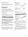
Transport
This appliance complies with one or more of the following
Standards:
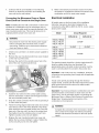
To avoid damage to the oven vent, use the transport
method shown in the picture below.
•
UL 858, Household Electric Ranges
•
UL 923, Microwave Cooking Appliances
•
UL 507, The Standard for the Safety of Electric Fans
•
CAN/CSA-C22.2
No. 113-M1984 Fans and Ventilators
It is the responsibility of the owner and the installer to
determine if additional requirements and/or standards
apply to specific installations.
Electric Safety
Before you plug in an electrical cord, be sure all controls
are in the OFF position.
If required by the National Electrical Code (or Canadian
Electrical Code), this appliance must be installed on a
separate branch circuit.
Installer - show the owner the location of the circuit
breaker or fuse. Mark it for easy reference.
English 1
Support the bottom of the oven from side to side when
moving it into the installation location. Leave the unit
attached to the shipping pallet until it is in front of the oven
cavity, ready to lift into place.
Preparation
Before You Begin
Use this checklist to verify that you have completed each
step of the installation process. This can help you avoid
common mistakes.
__
Tools and Parts Needed
•
Phillips head screwdriver
•
Star head screwdriver (T20)
•
Measuring tape
•
Drill with bit (1/8")
Parts Included
•
1. Before installing the oven, be sure to verify the
cabinet dimensions are correct for your unit and
the required electrical connections are present.
,
__
3.
Remove the oven door(s) to reduce the unit weight
and to provide access to handholds for lifting.
__
4.
Move the oven unit into place in front of the cabinet
opening, leaving the bottom packaging on the unit
to avoid damaging flooring.
__
5
Remove the T20 screws holding the unit to the
base of the carton (using Star-head screwdriver).
__
6.
If installing a combination unit (oven and
microwave or oven and steam oven) complete the
assembly before installing the unit.
Phillips head screws (6)
General Information
Refer to the installation manual for content
regarding Safety, Cabinet Dimensions, Removing
Packaging, Electrical Installation, Testing the
Installation and Customer Service.
Power Requirements
The outlet must be properly grounded in accordance with
all applicable codes.
For Best Installation
The oven can be difficult for two people to handle during
installation. It is recommended to have three or more
people available to assist with lifting the unit into place.
Removal of the bottom hinge oven door during installation
(to provide the necessary handholds and to significantly
reduce the unit weight) can be cumbersome unless the
detailed door removal instructions are followed carefully.
,
Team lift the unit directly into the cabinet cutout
taking care not to pinch fingers or scratch hands or
arms. Make sure the electrical conduit reaches to
the connection point properly.
__
8.
Slide the unit all the way into place, making sure to
route the electrical conduit correctly.
Note: Do not attempt to remove the side hinge door (some
models).
__
8.
Fasten the oven unit to the cabinetry opening with
the screws supplied (using Philips screwdriver).
Please take time to read and follow the instructions
provided for an improved installation experience.
__
10. Reinstall the oven door(s) removed in step 2
above.
__
11. Consult the complete installation instructions and
follow the remainder of the procedures listed,
including performing an operation test.
__
12. All product literature and accessories (may be
wrapped or boxed) with the oven.
__
13. INSTALLER - Leave the literature pack and the
accessories with the customer.
English 2
Dimensions and Cabinet Requirements
Cabinet requirements vary depending on the model to be
installed. Please consult the "Cabinet Dimension
Requirements" section at the back of this installation
manual for the details pertaining to your particular model.
All models require:
1/4" (6.4 mm) space between the side of the oven and
an adjacent wall or cabinet door when installed at the
end of a cabinet run.
support. This supporting base must be well secured to
the floor/cabinet and must be level.
The electrical conduit box must be located above the
unit to facilitate connecting and servicing the unit.
The cabinet base must be flat and capable of
supporting the weight of your oven when in use (varies
by model up to 429 Ibs. (195 kg)). See the appropriate
weight for your model in the "Cabinet Dimensions
Requirements" section at the back of this installation
manual.
Installation of 2x4's extending front to back flush with
the bottom and side of the opening to provide oven
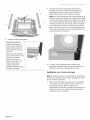
Removing Packaging
•
Cut straps on outside of box.
•
Remove cardboard box.
•
Remove all top and side cardboard and Styrofoam
braces.
•
Place oven in front of cabinets where it is to be
installed.
•
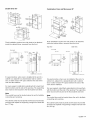
Unscrew unit from Left and Right Brackets as show in
"Left and Right Packaging Bracket Removal."
Right Packaging Bracket Removal
Left Packaging Bracket Removal
Note:
Different models use different packaging materials. Actual
brackets may look differently. Bracket remains in packaging
base. Unit should stay on packaging base until ready to be
lifted into cabinet cutout.
Preparing Oven
Place oven in front of cabinets where it is to be installed.
Rest it on a sturdy support so that it is in line with the
cabinet cutout.
English 3
Installation
Determine the Installation Type
This installation manual provides instructions for the
installation of single ovens, double ovens and combination
ovens (a single oven combined with with microwave or
steam oven).
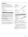
Parts Provided
Universal connector
bracket (2)
(in parts box on top of
oven)
Parts Provided
Oven Bottom trim (1)
Screws (16)
Packed in a plastic sleeve, with mounting screws in a
red bag within the sleeve
(in red bag, inside parts
box on top of oven)
Decorative trim (1)
Packed in bubble wrap, near the oven control panel.
Standalone single and double oven units require no
pre-assernbly. Unless you are installing a combination
oven, skip over the combination oven pre-assembly
instructions and go directly to "Electrical Installation"
which applies to all ovens.
Pre-Assembly of Combination
Prior to Installation
Ovens
Combination ovens (with microwave or steam oven)
require the units to be assembled together prior to installing
the combination unit into the wall cabinet.
Note: The single oven can be installed with a Steam Oven
or with a Microwave Oven. The installation procedure
differs between these. The parts contained in the square
tube parts box are common to both installations.
Combo service slide
assembly (2)*
* This part is
preassembled on the
oven to accomodate
attachment of a
microwave.
Installation
with the Microwave
Oven
Note: Do not place the oven into the wall cabinet until after
mounting the microwave on it using the universal connector
brackets.
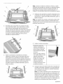
1.
The combo service slide assemblies are attached to
the oven spaced to accept the microwave.
2.
Install both universal connector brackets using six of
the screws provided. Tighten screws securely, but do
not overtighten.
Note: The universal connector brackets are interchangeable for the left and right sides of the oven. Be sure the
taller vertical edge of the bracket is positioned to the outside of the oven.
English 4
ii:il]_iO!_l'liii::]i_ii!ii%:ili!_iiiiiiiOi;i_
OV,@I;I_!i::::_l@di!i_!!il;,_!!ii)@!_l'liii::]i!ii!)iJ
_¸
,
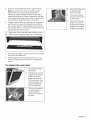
Place the microwave oven unit on top of the universal
connector brackets and fasten in place using three
screws per side. Tighten the screws securely, but do
not overtighten.
Note: The existing screws in the microwave base help
with alignment. When lowering the microwave into
place on the universal connector bracket, allow these
screw heads to slide into the slots as shown in the
illustration below. The screw nearest the front of the
microwave slides into the base of the slope at the front
of the bracket.
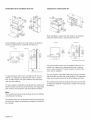
3.
Install the decorative trim.
Position the decorative trim
piece so the flanges with
the holes in them face
away from the oven door.
Align the outer flanges with
the outside of the universal
brackets. Fasten with 1
screw each into the end
hole of the universal
bracket. Tighten screws
securely, but do not
overtighten.
,
Continue with the unit installation in the following
sections on electrical connection and installing the
oven unit into the wall cabinet.
Installation
with the Steam Oven
Note: Do not place the oven into the wall cabinet until after
mounting the steam oven on it using the universal connector brackets.
,
English 5
Remove the six screws holding the combo service slide
assemblies to the support bracket. Use a magnetic
screwdriver bit to reach the screws through the large
holes in the tops of the slides.
,
The screw in position A (nearest the inside edge, near
control panel) must be moved to allow the universal
bracket to be postioned there. Remove the inside
screw (A) from the left support bracket and reinsert it
into the third hole (B) from the inside edge of the
support bracket. Repeat for the right support bracket.
taller vertical edge of the bracket is positioned to the outside of the oven.
B
5.
Install the decorative trim.
Position the decorative trim
,
Reattach the slide assemblies using the holes near the
inside edge of the support bracket. Align the slide
assembly parallel to the edge of the bracket and insert
the first screw in hole (C). Insert all three screws for
each slide assembly. Tighten the screws securely, but
do not overtighten.
piece so the flanges with
the holes in them face
away from the oven door.
Align the inner flanges with
the inside of the universal
brackets. Fasten with one
screw each into the end
hole of the universal
bracket. Tighten screws
securely, but do not
overtighten.
,
Note: When the correct holes are used, the front of the
slide assembly will extend just past the edge of the horizontal support bar. The slide assembly will be about 118" (3
mm) from the inside edge of the support bracket.
4.
Place the steam oven unit on top of the universal
connector brackets and fasten in place using two
screws per side. Tighten the screws securely, but do
not overtighten.
Note: The existing screws in the steam oven base help
with alignment. When lowering the steam oven into
place on the universal connector bracket, allow these
screw heads to slide into the slots as shown in the
illustration below. The screw nearest the front of the
steam oven slides into the base of the slope at the front
of the bracket.
Install the two universal connector brackets to the slide
assemblies using the screws provided. Tighten screws
securely, but do not overtighten.
Note: The universal connector brackets are interchangeable for the left and right sides of the oven. Be sure the
English 6
7. Continue
withtheunitinstallation
inthefollowing
sectionsonelectricalconnection
andinstallingthe
ovenunitintothewallcabinet.
8.
Connecting the Microwave Oven or Steam
Oven Electrical Conduit to the Single Oven
Electrical
Refer to the Electrical Connection section for further
information to complete the electrical connection of the
combination unit to the main power supply.
Installation
All model ovens on the front cover of this installation
Note: If installing the oven with a microwave or steam oven
mounted as a combination unit, the microwave oven or
steam oven power cable must be properly attached to the
oven-mounted junction box. This must be done prior to
supplying electric power to the oven unit.
instruction manual are dual rated, designed to be
connected to either 208 or 240V AC, 60 Hz, 4 wire, singlephase power supply.
Model
Circuit Required
208V, 60 Hz
WARNING
Disconnect the oven from the electric power supply
before connecting the microwave oven or steam
oven wiring. Failure to do so could result in electrical
shock and injury or death.
1.
Check to be sure there is no electric power supplied to
the oven.
2.
Remove the oven mounted junction box cover (located
on the rear top of the oven).
3.
Remove the cap from the conduit access hole in the
side of the oven mounted junction box.
HBN54, HBN84,
HBL53, HBL54,
HBL84, HBLP4
HBL55
HBN56,
HBL57,
HBL86,
HBLP6,
HSLP7
30 AMP
30 AMP
HBL56,
HBN86,
HBL87,
HBLP7,
240V, 60 Hz
40 AMP
40 AMP
The electrical supply should be a 4-wire single-phase AC.
Install a suitable conduit box (not furnished). An
appropriately-sized, UL-listed conduit connector must be
used to correctly attach the conduit to the junction box.
Important: Local Codes may vary; installation, electrical
connections and grounding must comply with all applicable
local codes.
If local codes permit grounding through the electrical
supply neutral, connect both the white neutral wire and the
green ground wire from the oven to the white neutral
electrical supply wire.
4.
Guide the four wires from the conduit cable coming
from the microwave or steam oven through the hole in
the oven mounted junction box.
5.
Snap the conduit connector into the hole by pressing it
in until it clicks into place.
6.
Follow the wiring diagram label and match and connect
each wire by color to the wires attached to the wiring
block inside the oven mounted junction box. Push the
bare end of the wire until it is snug in the wiring block
then tighten down the retaining screw on each wire.
Tighten securely, but do not over tighten.
7.
Replace the oven mounted junction box cover and
tighten the two screws holding it in place. Tighten the
screws securely, but do not over tighten.
English 7
Important: If you have purchased a combination oven unit
(one that includes a microwave or steam oven over the
single oven), see the preceding section "Connecting the
Microwave Oven or Steam Oven Electrical Conduit to the
Single Oven" showing electrical connection of the
combination unit components.
WARNING
Complete the connection of the microwave or steam
oven conduit to the single oven before proceeding
with the unit electrical connection to the main power
supply.
Electrical
Connection
to Main Power Supply
The four-wire connection is preferred, but where local
codes permit, the three wire connection is also acceptable.
Note:
Four-wire Connection
Ungrounded Neutral
Before installing the oven, be sure to verify the cabinet
dimensions and electrical connections.Check that the
power supply
junction
Installing the Oven Unit into
the Wall Cabinet
cavity is level and plumb for correct installation.
box --÷
black wires
Combination units (ovens with a microwave or steam oven)
have additional installation instructions. Please see the
red wires
preceeding section "Pre-Assembly of Combination Ovens
Prior to Installation".
green or bare
wire
white wires
green wire
UL listed
connector
•
cable from
oven
•
Connect the red oven wire to the red electrical supply
wire (hot wire).
Connect the black oven wire to the black electrical
•
supply wire (hot wire).
Connect the white neutral oven wire to the white
neutral (not bare or green ground) electrical supply
wire.
•
Connect the green ground oven wire to the bare or
green ground electrical supply wire.
Three-wire Connection
Grounded Neutral
power supply
junction
For Best Installation
The double and combination ovens can be difficult for two
people to handle during installation. It is recommended to
have three or more people available to assist with lifting the
unit into place. It is also recommended to remove the oven
door (bottom hinge models only) to help reduce the unit
weight and provide easier access to the handholds inside
the oven cavity.
Removing the Bottom Hinge Oven Door
Important: Do not attempt to remove the side hinge
door (some models).
For ease of installation, some oven doors may be removed
to reduce the weight of the oven by 30 Ibs (14 kg) per door,
before installing into the cabinet. See instructions below.
_-
box
black wires
red wires
white,
"_N
WARNING
bare, or
green wire
UL listed
•
Make sure oven is cool and power to the oven
has been turned off before removing the door.
Failure to do so could result in burns.
•
The oven door is heavy and fragile. Use both
hands to remove the oven door. The door front
connector
white wire
green
•
•
wire
cable from
oven
is glass. Handle carefully to avoid breaking.
Connect red wire from oven to red wire in junction box.
Connect black wire from oven to black wire in junction
box.
Connect both green ground wire and white wire from
oven to white, green or bare neutral wire in junction
box.
The conduit cable, where connected at the oven, swivels.
Rotate conduit cable upward (or downward) and direct
through hole prepared in cabinet to attach to J-Box.
To maintain serviceability, the flex conduit must not be
shortened and should be routed to permit temporary
removal of the oven.
•
Grasp only the sides of the oven door. Do not
grasp the handle as it may swing in your hand
and cause damage or injury.
•
Failure to grasp the oven door firmly and
properly could result in personal injury or
product damage.
•
To avoid injury from hinge bracket snapping
closed, be sure that both levers are securely in
place before removing the door. Also, do not
force door open or closed - the hinge could be
damaged and injury could result.
•
Do not lay removed door on sharp or pointed
objects as this could break the glass. Lay on a
flat, smooth surface, positioned so that the
door cannot fall over.
English 8
To remove
the oven door:
,
Be sure to read the
above WARNING
before attempting to
remove the door.
2.
Open the door
completely.
3.
Flip levers on hinges
toward you.
,
Holding the door firmly
on both sides and
using both hands,
close the door gently
until it stops against
the levers, about 30 °
from the closed
position.
5.
Carefully lift the door
up and out of the
hinge slots. Hold
firmly; the door is
heavy.
6.
Place the door in a
convenient and stable
location unitl you are
ready to reinstall it.
1.
The unit and its bottom packaging (pallet) should be
positioned close to and in front of the cabinet opening
prior to beginning to lift the unit into place.
Placing the Oven Into the Cabinet
Opening
CAUTION
To avoid damage to the door do not lift, pull or push
the unit during installation by using the oven door
handle as a gripping point.
Note:
It is recommended to wear gloves and long sleeves
to protect hands and forearms from abrasion and
potential scratches during the lifting process. It is
also recommended to take off watches and jewelry
and to wear work shoes during installation for foot
protection.
When lifting the unit into place avoid grasping the upper
element to avoid damaging it. See the illustration following
for the correct lifting point.
,
3.
Lift or slide unit into the cabinet cutout without allowing
the unit base to contact the flooring.
Check that the conduit cable does not fall behind the
unit during installation. It may help to run the conduit
into the area it will be connected to (such as an
overhead or adjacent cabinet) and tape the end down
so it doesn't fall out while the unit is being slid into
place.
English 9
4. Guidetheunitstraightbackintothecabinetcutout.
4.
Open door all the way
to expose hinges,
levers, and slots.
5.
Push levers forward
and down until seated
on the bracket.
Note: Be careful not to crimp the flexible conduit
between the oven and the cabinet back wall. If
necessary, guide the flexible conduit into the wall or
cabinet access hole so it doesn't prevent the unit from
being pushed all the way into the cabinet opening. The
oven should be straight and level, not crooked.
5.
Install the oven bottom trim while the door is removed
and the unit is in place. (Do not push the unit all the
way in, leave about 1 inch extending from the front of
the cabinet). Use two of the screws provided in the red
bag included with the trim piece.
1.
Align holes in trim ends with holes at bottom of oven.
2.
Insert screws and tighten firmly. Do not overtighten.
,
Close and open door
slowly to be sure it is
correctly and securely
in place. Door must be
straight, not crooked.
\
\
,
4.
Push the unit straight in until the oven trim is flush with
the front of the cabinet trim.
Install supplied screws through tap holes in trim. (2
screws for single ovens, 4 screws for double/combo
ovens).
To replace the oven door:
1.
,
Hold the door firmly in
both hands.
Hold the door at a 30 °
angle from the closed
position and insert
hinges into the slots.
You may need to rock
the door forward and
backward slightly to
seat the hinge feet.
,
The door may need to
be removed and reinserted until the
hinges sit correctly in
the slots.
English 10
Testing Operation
1.
Turn on power at the breaker.
2.
Test the oven mode.
Select the BAKE mode. See the Use and Care Manual
for detailed operation instructions.
3.
4.
Verify that the oven light comes on and the oven begins
to preheat.
Test the door lock.
Set the SELF CLEAN mode. Confirm that the door
locks when the lock icon appears in the display.
5.
If installing a double oven, test the second oven as
well.
6.
If any of the tests do not result as explained above,
contact Bosch service for assistance. Otherwise, the
installation is complete at this time.
Service
Before Calling Service
See Use and Care Manual for troubleshooting information.
Refer to the Warranty in the Use and Care Manual.
To reach a service representative, see the contact
information at the front of the manual. Please be prepared
with the information printed on your product data plate
when calling.
Data Plate
The data plate shows the model and serial number. Refer
to the data plate on the appliance when requesting service.
The data plate is located on the underside of the control
panel.
Data
Plate
English 11
Cabinet Dimension Requirements
Dimensions
for 27" Wall-Mounted
Units
Double Oven 27"
Single Oven 27"
50"
_'_
(1270)
m&x. 38"
p
29"
269/16"
(737)
(674)
.....
*
rain.
(121-964
(121
-_(568)
For single ovens installed in a wall cabinet, the junction
box may be located above or beneath the unit within
reach of the power cable.
Flush installation requires two side cleats to be attached
inside the cabinet frame, recessed from the front.
Flush Install
Top View
*
For single ovens installed in a wall cabinet, the junction
box may be located above or beneath the unit within
reach of the power cable.
Flush installation requires two side cleats to be attached
inside the cabinet frame, recessed from the front.
Side View
1"
89/16"
(218)
c!9_t,
(25)
Flush
installation
Top
1"
Side view
view
89/16"
24518"
(625)
!/8" I_ats (22)
(;5
7/d'
cleats
(22)
-FF...............
qq_
251'2" (648) _1
27_/4" (692)
et
J
i(674)--'_-
II
i_r°guct I
II
__
29114"
241/2"
(744)
flush
cut out
height
(622)
Flush inset
depth
Cleats
52 3/8"
'&
!
_5_
493/4
495/8"
(1260)
(1211)
"
(t264)
Openin{
cut-out
1330)
F ush
cut-out
height
:
241/2".___
(622)
measurements
in inches (ram)
4711/16.
It is good practice, when oven is installed at the end of a
cabinet run, adjacent to a perpendicular wall or cabinet
door, to allow at least 114" space between the side of the
oven and the wall/door.
For oven support, install 2x4's extending front to back flush
with the bottom and the side of the opening. The supporting
base must be well secured to the floor/cabinet and level.
Note:
The conduit box can be installed above or to the right of the
unit, within range of the power conduit.
The cabinet cavity must be plumb and the base must be flat
and level and capable of supporting a weight of at least 193
Ibs (87 kg).
P_°dih_t
night
24112"
(622)
measurements
in inches
(ram)
It is good practice, when oven is installed at the end of a
cabinet run, adjacent to a perpendicular wall or cabinet
door, to allow at least 114"space between the side of the
oven and the wall/door.
For oven support, install 2x4's extending front to back flush
with the bottom and the side of the opening. The supporting
base must be well secured to the floor/cabinet and level.
Note:
The conduit box must be located above the unit to facilitate
connecting and servicing.
English 12
Thecabinetcavitymustbeplumbandthebasemustbeflat
andlevelandcapableofsupporting
aweightofatleast361
Ibs(164kg).
Dimensions
for 30" Wall-Mounted
Units
Single Oven 30"
Single Oven, Undercounter 27"
27-285/8"
50"
(674)
*
For single ovens installed in a wall cabinet, the junction
box may be located above or beneath the unit within
reach of the power cable.
Flush installation requires two side cleats to be attached
inside the cabinet frame, recessed from the front.
Flush Install
Top View
1"
89/16"
(218)
et
'8" (22)
_at_s__
7/8" (22)
cleati__
11 /
depth
cleat
(25)
Flush Install
T
m
e(
_i
24 /8"
t_9_
_v._,
I
I _cPut
o'u?
'
9 ,,
I 26/16
height
_o74)
I
I product
I
iheig_t
__
89/16"
(2t8)
i
i
1
1
1
1
i
i
i
i
i
i
i
--
(622)
measurements
Side View
(744)
flush
cut out
height
;
241/2"
Top View
291/4.
1
_
27 /4" (692) -_"1
Flush installation requires two side cleats to be attached
inside the cabinet frame, recessed from the front.
Side View
_T_I
in inches (mm)
It is good practice, when oven is installed at the end of a
cabinet run, adjacent to a perpendicular wall or cabinet
door, to allow at least 114" space between the side of the
oven and the wall/door.
For oven support, install 2x4's extending front to back flush
with the bottom and the side of the opening. The supporting
base must be well secured to the floor/cabinet and level.
The cabinet base must be flat and capable of supporting a
weight of at least 193 Ibs (87 kg).
i
i
i
'15/8" (41)
____cleats
7/8"(22
cleati_._
_:====:====:====:=_j=-
(
(
L_281/2.
_,_
(724) ___
31" (787)
-_
-'t
t
241/2"
(622)
flush inset
depth
_!
1"
cleats
b-\_'--
......
/
i
/
/
I
/
245/8.
625_
"
"
I
/
(25)
.
T
(686)
II
epentngl
! 269/16,, cutoutll
l
_;A_
hefghtll
l _u._j
29_/_"
I
(744)
flush
cut out
height
et
IProduct I II
,
I height / II
|
_
__L
__
241/2" __
(622)
measurements
in inches (mm) '_)
It is good practice, when oven is installed at the end of a
cabinet run, adjacent to a perpendicular wall or cabinet
door, to allow at least 114"space between the side of the
oven and the wall/door.
For oven support, install 2x4's extending front to back flush
with the bottom and the side of the opening. The supporting
base must be well secured to the floor/cabinet and level.
Note:
The conduit box must be installed either above or below the
unit. If the conduit box is installed below the unit, a 2"
diameter hole or space is required between the back wall
and the right rear of the 2x4 supports.
The cabinet cavity must be plumb and the base must be flat
and level and capable of supporting a weight of at least 212
Ibs (96 kg).
English 13
Double Oven 30"
Combination
Oven and Microwave 30"
>
(1264-1308)
485;8"
t3
5_
J
/
Flush installation requires two side cleats to be attached
inside the cabinet frame, recessed from the front.
Flush installation requires two side cleats to be attached
inside the cabinet frame, recessed from the front.
Top View
Flush Install
Flush Install
7/8"
(22)i
s2
52 318"
241/2"
depth
flush
height
cleats_t _
1_281/2" (724) *1
7/8"
vl
1"
(25F r_
30 /4 (768
I_
t,
241/2"
(622)
measurements
(22)
p cmeats
7/8" (22)I
49 1/4"
(1251)
flush
cut out
height
241/2"
(622)
flush inset
depth
(1330)
cut out
I,,,cleats
1"
Side View
Top View
1"
Side View
Top View
7/8" (22)
Side View
]
cUeat]s't
281/2" (724) _1
q
301/4" (768)
241/2 ,'
in inches
(622)
(ram)
measurements
It is good practice, when oven is installed at the end of a
cabinet run, adjacent to a perpendicular wall or cabinet
door, to allow at least 114" space between the side of the
oven and the wall/door.
For oven support, install 2x4's extending front to back flush
with the bottom and the side of the opening. The supporting
base must be well secured to the floor/cabinet and level.
Note:
The conduit box must be located above the unit to facilitate
connecting and servicing.
b-
in inches (ram)
It is good practice, when oven is installed at the end of a
cabinet run, adjacent to a perpendicular wall or cabinet
door, to allow at least 114"space between the side of the
oven and the wall/door.
For oven support, install 2x4's extending front to back flush
with the bottom and the side of the opening. The supporting
base must be well secured to the floor/cabinet and level.
Note:
The conduit box must be located above the unit to facilitate
connecting and servicing.
The cabinet cavity must be plumb and the base must be flat
and level and capable of supporting a weight of at least 390
Ibs (177 kg).
The cabinet cavity must be plumb and the base must be flat
and level and capable of supporting a weight of at least 310
Ibs (141 kg).
English 14
Combination
Oven and Steam Oven 30"
Single Oven, Undercounter 30"
<
48%"
3_
5;
f
7
f
Flush installation requires two side cleats to be attached
inside the cabinet frame, recessed from the front.
"TopView
Flush installation requires two side cleats to be attached
inside the cabinet frame, recessed from the front.
Side
(2_8)
Flush instal[
491_ ,,
(125!)
flush
cut out
height
241/2,,
7/8" (22)
t.ccBeats
cBeats
(622)
flush inset
depth
(¢22)
flush
ir_sel
depth
l ...........................
heigh_
: _
I
(e22
_ inche_ {ram)
(768)_
It is good practice, when oven is installed at the end of a
cabinet run, adjacent to a perpendicular wall or cabinet
door, to allow at least 114"space between the side of the
oven and the wall/door.
241/2"
(622)
measurements
in inches (ram)
It is good practice, when oven is installed at the end of a
cabinet run, adjacent to a perpendicular wall or cabinet
door, to allow at least 114" space between the side of the
oven and the wall/door.
For oven support, install 2x4's extending front to back flush
with the bottom and the side of the opening. The supporting
base must be well secured to the floor/cabinet and level.
Note:
The conduit box must be located above the unit to facilitate
connecting and servicing.
The cabinet cavity must be plumb and the base must be flat
and level and capable of supporting a weight of at least 429
Ibs (195 kg).
English 15
301/4"(768} .........:
:
Measureme.n_
281/2" (724)
_30_/4"
625)
_l_eats
,
(25)_
I_
_:!_:_t_
(25)
Side View
Top View
!7/8" (22)
View
For oven support, install 2x4's extending front to back flush
with the bottom and the side of the opening. The supporting
base must be well secured to the floor/cabinet and level.
The cabinet cavity must be plumb and the base must be flat
and level and capable of supporting a weight of at least 212
Ibs (96 kg).
English16
English17
f
Indice
Seguridad
...........................
Antes de comenzar ....................
Herramientas y partes necesarias
Partes incluidas .......................
Informaci6n
Dimensiones
general
1
2
.........
2
2
....................
y requisitos
2
de los gabinetes
4
Retiro del embalaje ....................
Preparaci6n del horno ..................
4
4
Instalacibn
5
...........................
Determinaci6n
del tipo de instalaci6n .......
5
Preensamblaje
de hornos combinados antes de
la instalaci6n ..........................
5
Instalaci6n electrica ....................
8
Instalacibn
del homo en
el gabinete de pared .................
Para una mejor instalaci6n ..............
Retiro de la puerta del horno de las bisagras
inferiores ............................
Para volver a colocar la puerta del homo:
Prueba de funcionamiento
.............
Servicio t_cnico
.....................
Antes de Ilamar al servicio tecnico
........
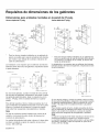
Requisitos de dimensiones
de los gabinetes .....................
Dimensiones
para unidades montadas
en la pared de 27 pulg ..................
Dimensiones
para unidades
montadas
en la pared de 30 pulg .................
10
10
10
.. 12
13
13
13
14
14
15
Este electrodomestico
de Bosch es fabricado
BSH Home Appliances Corporation
1901 Main Street, Suite 600
Irvine, CA 92614
por
6Tiene preguntas?
1-800-944-2904
www. bosch-home.com
iEsperamos
recibir sus comentarios!
INSTRUCCIONES
LEA Y CONSERVE
DE SEGURIDAD
IMPORTANTES
ESTAS INSTRUCCIONES
Seguridad
ADVERTENCIA:
Seguridad con la electricidad
Si no sigue exactamente la informaci6n de este manual, se
pueden producir un incendio o una explosi6n que pueden
causar da_os materiales o lesiones personales.
Antes de enchufar un cable el6ctrico, asegQrese de que
todos los controles est6n en la posici6n OFF (Apagado).
ADVERTENCIA:
No repare ni reemplace ninguna parte del
electrodom6stico, a menos que se recomiende
especificamente en los manuales. La instalaci6n, el
servicio t6cnico o el mantenimiento incorrectos pueden
causar lesiones o da_os materiales. Consulte este manual
para su orientaci6n. Todo servicio t6cnico debe ser
realizado por un t6cnico calificado.
Seguridad con el manejo del electrodomestico
No levante el electrodom6stico desde el mango de la
puerta. Retire la puerta para que sean m_s f_ciles la
manipulaci6n y la instalaci6n. Consulte las instrucciones
que figuran en el Manual de uso y cuidado.
La unidad es pesada y se requieren al menos dos
personas o un equipo adecuado para trasladarla.
Las superficies ocultas pueden tener bordes filosos.
Proceda con cuidado al intentar tomar el electrodom6stico
por la parte trasera o desde abajo.
Codigos y normas de seguridad
Este electrodom6stico
siguientes normas:
cumple con una o m_s de las
•
UL 858, Estufas el6ctricas de uso dom6stico
(Household Electric Ranges)
•
UL 923, Electrodom6sticos de cocci6n por microondas
(Microwave Cooking Appliances)
•
UL 507, Norma de seguridad para ventiladores
el6ctricos (Standard for the Safety of Electric Fans)
•
CAN/CSA-C22.2
and Ventilators)
No. 113-M1984 Ventiladores (Fans
Es responsabilidad del propietario y del instalador
determinar si se aplican otros requisitos y/o normas en
instalaciones especificas.
Espa_oll
Si Io requiere el C6digo Nacional EI6ctrico (National
Electrical Code), este electrodom6stico debe instalarse en
un circuito derivado por separado.
Instalador: muestre al propietario la ubicaci6n del
disyuntor o del fusible. MSrquela para identificarla m_s
fScilmente.
Irnportante: conserve estas instrucciones para uso del
inspector de electricidad local.
Antes de realizar la instalaci6n, apague la alimentaci6n
el6ctrica en el panel de servicio. Trabe el panel de servicio
para impedir que se encienda accidentalmente la
alimentaci6n el6ctrica.
Consulte la placa de datos para obtener m_s informaci6n.
Consulte "Placa de datos" en la secci6n "Servicio t6cnico"
para conocer la ubicaci6n de la placa de datos.
AsegQrese de que el electrodom6stico sea correctamente
instalado y conectado a tierra por un t6cnico calificado. La
instalaci6n, las conexiones el6ctricas y la conexi6n a tierra
deben cumplir con todos los c6digos correspondientes.
Seguridad del equipo relacionado
Retire toda la cinta y el embalaje antes de usar el
electrodom6stico. Destruya el embalaje despu6s de
desembalar el electrodom6stico. Nunca deje que los ni_os
jueguen con el material de embalaje.
Nunca modifique ni altere la construcci6n del
electrodom6stico. Por ejemplo, no retire las patas
niveladoras, los paneles, las cubiertas de cables ni los
soportes/tornillos anticaidas.
Transporte
Para evitar da_os al ventilador del horno, utilice el m6todo
de transporte que se muestra en la imagen que figura a
continuaci6n.
La manipulaci6n del homo durante la instalaci6n puede
resultar dificil si la realizan dos personas. Se recomienda
que haya tres o m_s personas disponibles para ayudar a
levantar la unidad y colocarla en su lugar.
Retirar la puerta del horno de las bisagras inferiores
durante la instalaci6n (para colocar los asideros necesarios
y para reducir el peso de la unidad en forma significativa)
puede presentar dificultades, a menos que se sigan con
cuidado las instrucciones detalladas para retirar la puerta.
Nota: No intente retirar la puerta de las bisagras laterales
(algunos modelos).
T6mese su tiempo para leer y seguir las instrucciones
proporcionadas para una mejor experiencia de instalaci6n.
Lista de verificacibn
Sostenga la parte inferior del homo de ambos lados al
moverlo a la ubicaci6n de instalaci6n. Deje la unidad atada
a la paleta de envio hasta que se encuentre en frente de la
cavidad del homo, lista para levantarla y colocarla en su
lugar.
Utilice esta lista de verificaci6n para controlar que haya
completado cada paso del proceso de instalaci6n. Esto
puede ayudarlo a evitar errores comunes.
,
,
Preparacibn
Antes de comenzar
Destornillador con cabeza Phillips
•
Destornillador
•
Cinta m6trica
•
Taladro con broca (1/8 pulg.)
con cabeza de estrella (T20)
Partes incluidas
•
3.
Retire la(s) puerta(s) del horno para reducir el peso
de la unidad y para facilitar el acceso a los
asideros a fin de levantarla.
__
4.
Mueva el horno y col6quelo en su lugar delante de
la abertura del gabinete, y deje la parte inferior del
embalaje en la unidad para evitar da_ar el piso.
__
5.
Retire los tornillos T20 que mantienen la unidad
sobre la base del cart6n (usando un destornillador
con cabeza de estrella).
Tornillos con cabeza Phillips (6)
,
Informacion general
Requisitos de alimentacion electrica
La toma de corriente debe estar correctamente
a tierra de acuerdo con todos los c6digos
correspondientes.
conectada
Para una mejor instalacibn
Consulte el manual de instalaci6n para obtener
informaci6n sobre Seguridad, Dimensiones del
gabinete, C6mo retirar el embalaje, Instalaci6n
el6ctrica, C6mo probar la instalaci6n y Servicio al
cliente.
__
Herramientas y partes necesarias
•
Antes de instalar el horno, asegQrese de controlar
que las dimensiones del gabinete sean adecuadas
para su unidad y que se hayan realizado las
conexiones el6ctricas requeridas.
,
Si se realiza la instalaci6n de un horno combinado
(homo y microondas, u horno y homo de vapor),
complete el ensamblaje antes de instalar la
unidad.
Levante la unidad con la ayuda de otra persona y
col6quela directamente en el recorte del gabinete y
tenga cuidado de no apretarse los dedos ni
rasparse las manos o los brazos. AsegQrese de
que el conducto el6ctrico Ilegue al punto de
conexi6n en forma apropiada.
Espa_ol2
__ 8.
,
dimensiones
delosgabinetes"
enlaparteposteriorde
estemanualdeinstalaci6n.
Deslice la unidad completamente hasta su lugar,
asegurSndose de direccionar el conducto el6ctrico
en forma correcta.
Ajuste el horno a la abertura de los gabinetes con
los tornillos que se suministran (usando el
destornillador Phillips).
10. Reinstale la(s) puerta(s) del horno que retir6 en el
paso 2 anterior.
11. Consulte las instrucciones de instalaci6n
completas y siga el resto de los procedimientos
mencionados, incluida la realizaci6n de una
prueba de funcionamiento.
12. Todo el material impreso y los accesorios del
producto (pueden estar envueltos o en una caja)
que pueden venir con el horno.
13. INSTALADOR: Deje al cliente el paquete de
material impreso y los accesorios.
Retiro del embalaje
•
Corte las correas que se encuentran en la parte
exterior de la caja.
•
Retire la caja de cart6n.
•
Retire todas las protecciones de cart6n y de Styrofoam
de la parte superior y lateral.
•
Coloque el horno frente a los gabinetes donde se va a
instalar.
Desatornille la unidad de los soportes izquierdo y
derecho, como se muestra en "Retiro de protecciones
izquierda y derecha del embalaje".
Retiro
del soporte
izquierdo
del embalaje
Dimensiones y
requisitos de los
gabinetes
Los requisitos del gabinete varian en funci6n del modelo
que se instalar_. Consulte la secci6n "Requisitos de
dimensiones de los gabinetes" que se encuentra en la
parte posterior de este manual de instalaci6n para obtener
los detalles pertinentes a su modelo en particular.
Retiro del soporte derecho del embalaje
Todos los modelos requieren Io siguiente:
•
Un espacio de 1/4 pulg. (6.4 mm) entre el costado del
homo y una pared o la puerta de un gabinete
adyacentes cuando se instalen al final de una serie de
gabinetes.
•
La instalaci6n de escuadras de 2 x 4 que se extiendan
de adelante hacia atr_s a ras de la parte inferior y el
costado de la abertura para brindar soporte al horno.
Esta base de soporte debe estar bien asegurada al
piso/gabinete y debe estar nivelada.
•
La caja de conductos el6ctricos debe estar ubicada por
encima de la unidad para facilitar la conexi6n y el
servicio t6cnico de la unidad.
La base del gabinete debe ser plana y capaz de
soportar el peso de su homo cuando est6 en uso (varia
por modelo hasta 429 Ib [195 kg]). Consulte el peso
adecuado para su modelo en la secci6n "Requisitos de
Espa_ol3
Nota:
Los diferentes modelos utilizan materiales de embalaje
diferentes. Los soportes reales pueden tener un aspecto
diferente. El soporte permanece en la base de embalaje.
La unidad debe permanecer en la base de embalaje hasta
que est6 lista para ser levantada y colocada en el recorte
del gabinete.
_@@
_2_::_i2i@
Preparacion
_@ _O_" o C;O_::_i _¸_O
del horno
Coloque el horno frente a los gabinetes donde se va a
instalar. Ap6yelo en un soporte resistente, de modo que
est6 alineado con el recorte del gabinete.
Partes proporcionadas
Soporte de conexi6n
universal (2)
(en la caja de partes que
se encuentra encima del
horno)
Instalacibn
Tornillos (16)
Determine
(en la bolsa roja, dentro de
la caja de partes que se
encuentra encima del
el tipo de instalacion
Este manual de instalaci6n proporciona instrucciones para
la instalaci6n de hornos simples, hornos dobles y hornos
combinados (un horno simple combinado con un horno de
microondas o de vapor).
Partes proporcionadas
horno)
Moldura decorativa (1)
Embalada en un envoltorio de burbujas, cerca del panel
de control del homo.
Guarnici6n inferior del horno (1)
Embalado en una funda de pl_stico, con tornillos de
montaje en una bolsa de color rojo dentro de la manga.
Ensamble de corredera de
servicio t6cnico para
combo (2)*
Los hornos autonornos sirnples y dobles no requieren
un preensarnblaje. Salvo que est6 instalando un horno
combinado, salte las instrucciones de preensamblaje de
hornos combinados y vaya direeto a "lnstala¢ion
electrica", que se aplica a todos los hornos.
* Esta parte se encuentra
preensamblada en el
horno para facilitar la
conexi6n de un
microondas.
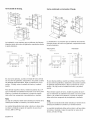
Instalacibn
con el horno de microondas
Preensamblaje de hornos combinados
antes de la instalacion
Nota: No coloque el horno en el gabinete de pared hasta
despu6s de montar el microondas utilizando los soportes
de conexi6n universales.
Los hornos combinados (con horno de microondas o de
vapor) requieren el ensamblaje de las unidades antes de la
instalaci6n de la unidad combinada en el gabinete de
pared.
1.
Los ensambles de corredera de servicio t6cnico para
combo est_n conectados al horno con espacios para
conectar el microondas.
2.
Nota: El homo simple puede instalarse con un homo de
vapor o con un horno de microondas. El procedimiento de
instalaci6n difiere entre estos dos. Las partes que se
encuentran en la caja de partes de tubo cuadradas son
comunes a las dos instalaciones.
Instale los dos soportes de conexi6n universales
utilizando seis de los tornillos proporcionados. Ajuste
los tornillos firmemente, pero no ajuste en exceso.
Nota: Los soportes de conexi6n universales pueden intercambiarse para los lados izquierdo y derecho del horno.
AsegQrese de que el borde vertical m_s alto del soporte
est6 posicionado fuera del homo.
Espa_ol4
_y_
,
_2_::_i_i_
_
_(_-
_:_C;(_i_::_i _¸_
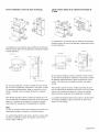
Coloque el horno de microondas encima de los
soportes de conexi6n universales y ajOstelo en su
lugar utilizando tres tornillos por lado. Ajuste los
tornillos firmemente, pero no ajuste en exceso.
Nota: Los tornillos existentes que se encuentran en la
base del microondas ayudan con la alineaci6n. AI bajar
el microondas para colocarlo en su lugar en el soporte
de conexi6n universal, deje que las cabezas de estos
tornillos se deslicen en las ranuras, como se muestra
en la ilustraci6n que figura a continuaci6n. El tornillo
que se encuentra m_s cerca de la parte delantera del
microondas se desliza en la base de la inclinaci6n en
la parte delantera del soporte.
3.
Instale la moldura decorativa.
Posicione la pieza de
moldura decorativa de
modo que las bridas que
tienen orificios apunten
hacia afuera de la puerta
del horno.
Alinee las bridas externas
con la parte exterior de los
soportes universales.
Ajuste cada una con 1
tornillo en el orificio del
extremo del soporte
universal. Ajuste los
tornillos firmemente, pero
no ajuste en exceso.
5.
ContinQe con la instalaci6n de la unidad en las
siguientes secciones sobre la conexi6n el6ctrica y la
instalaci6n del horno en el gabinete de pared.
Instalacibn
con el horno de vapor
Nota: No coloque el horno en el gabinete de pared hasta
despu6s de montar el horno de vapor utilizando los soportes de conexi6n universales.
,
Espa_ol 5
Retire los seis tornillos que sostienen los ensambles
de corredera de servicio t6cnico para combo en la
escuadra de soporte. Utilice la punta de un
destornillador de berbiqui magn6tico para alcanzar los
tornillos a trav6s de los orificios largos en las partes
superiores de las correderas.
Nota: Cuando se utilizan los orificios correctos, la parte
delantera del ensamble de corredera se extender8 apenas
pasando el borde de la barra de soporte horizontal. El
ensamble de corredera estar& aproximadamente, a 1/
8 pulg. (3 mm) del borde interior de la escuadra de soporte.
/
/
/
/
//
4.
Instale los dos soportes de conexi6n universales en los
ensambles de corredera utilizando los tornillos que se
proporcionan. Ajuste los tornillos firmemente, pero no
ajuste en exceso.
Nota: Los soportes de conexi6n universales pueden intercambiarse para los lados izquierdo y derecho del horno.
AsegOrese de que el borde vertical m_s alto del soporte se
posicione fuera del horno.
,
El tornillo que se encuentra en la posici6n A (m_s
cerca del borde interior, cerca del panel de control)
debe moverse para permitir que se posicione el
soporte universal alli. Retire el tornillo interno (A) de la
escuadra de soporte izquierda y vuelva a introducirlo
en el tercer orificio (B) desde el borde interno de la
escuadra de soporte. Repita los pasos para la
escuadra de soporte derecha.
B
5.
Instale la moldura decorativa.
Posicione la pieza de
moldura decorativa de
modo que las bridas que
tienen orificios apunten
hacia afuera de la puerta
del horno.
,
Vuelva a conectar los ensambles de corredera
utilizando los orificios que se encuentran cerca del
borde interior de la escuadra de soporte. Alinee el
ensamble de corredera en forma paralela al borde del
soporte e introduzca el primer tornillo en el orificio (C).
Introduzca los tres tornillos de cada ensamble de
corredera. Ajuste los tornillos firmemente, pero no
ajuste en exceso.
Alinee las bridas internas
con la parte interior de los
soportes universales.
Ajuste cada una con un
tornillo en el orificio del
extremo del soporte
universal. Ajuste los
tornillos firmemente, pero
no ajuste en exceso.
,
Coloque el horno de vapor encima de los soportes de
conexi6n universales y ajQstelo en su lugar utilizando
dos tornillos por lado. Ajuste los tornillos firmemente,
pero no ajuste en exceso.
Nota: Los tornillos existentes que se encuentran en la
base del horno de vapor ayudan con la alineaci6n. AI
bajar el homo de vapor para colocarlo en su lugar en el
soporte de conexi6n universal, deje que las cabezas
de estos tornillos se deslicen en las ranuras, como se
muestra en la ilustraci6n que figura a continuaci6n. El
tornillo que se encuentra m_s cerca de la parte
Espafiol6
delantera
delhornodevaporse deslizaenlabasede
la inclinaci6n
enlapartedelantera
delsoporte.
,
7. ContinQe
conlainstalaci6n
dela unidadenlas
siguientes
secciones
sobrelaconexi6nel6ctricay la
instalaci6n
delhornoenelgabinetedepared.
Conexibn del conducto el_ctrico del homo de
microondas o del homo de vapor al homo
simple
Nota: Si se realiza la instalaci6n del homo con un horno de
microondas o de vapor montados como unidad combinada,
el cable de alimentaci6n el6ctrica del horno de microondas
o del horno de vapor debe estar adecuadamente
conectado a la caja de empalme montada en el horno. Esto
debe realizarse antes de suministrar energia el6ctrica al
horno.
ADVERTENCIA
Desconecte el horno de la fuente de alimentaci6n
el6ctrica antes de conectar el cableado del horno de
microondas o del horno de vapor. No hacerlo podria
producir una descarga el6ctrica y lesiones o la
muerte.
,
AsegQrese de que no se suministre energia el6ctrica al
horno.
2.
Retire la cubierta de la caja de empalme montada en el
horno (ubicada en la parte trasera superior del homo).
3.
Retire la tapa del orificio de acceso al conducto que se
encuentra al costado de la caja de empalme montada
en el horno.
Guie los cuatro cables del cable de conductos que
proviene del horno de microondas o de vapor a trav6s
del orificio que se encuentra en la caja de empalme
montada en el horno.
5.
Calce a presi6n el conector de conductos en el orificio
presion_ndolo en su lugar hasta que haga un clic.
6.
Siga la etiqueta de diagrama de cableado, y haga
coincidir y conecte cada cable por color a los cables
conectados al bloque de cableado que se encuentra
dentro de la caja de empalme montada en el homo.
Empuje el extremo desnudo del cable hasta que quede
ajustado en el bloque de cableado; luego, ajuste el
tornillo de retenci6n sobre cada cable. Ajuste
firmemente, pero no ajuste en exceso.
7.
Vuelva a colocar la cubierta de la caja de empalme
montada en el horno y ajuste los dos tornillos que la
mantienen en su lugar. Ajuste los tornillos firmemente,
pero no ajuste en exceso.
8.
Consulte la secci6n "Conexi6n el6ctrica", a fin de
obtener m_s informaci6n para completar la conexi6n
el6ctrica de la unidad combinada a la fuente de
alimentaci6n principal.
Instalacion
electrica
Todos los hornos modelo que figuran en la portada de este
manual de instrucciones de instalaci6n presentan una
clasificaci6n doble, est_n dise_ados para conectarse a una
fuente de alimentaci6n monofSsica de 208 V o 240 V CA,
de 60 Hz, de 4 cables.
Modelo
Circuito requerido
208 V, 60 Hz
HBN54, HBN84,
HBL53, HBL54,
HBL84, HBLP4
HBL55
Espa_ol 7
240 V, 60 Hz
30 A
30 A
/
I
40 A
Modelo
Circuito requerido
208 V, 60 Hz
HBN56,
HBL57,
HBL86,
HBLP6,
HSLP7
HBL56,
HBN86,
HBL87,
HBLP7,
Conexibn
principal
el_ctrica
a la fuente de alimentacibn
240 V, 60 Hz
Se prefiere la conexi6n de cuatro cables, pero, si Io
permiten los c6digos locales, tambi6n es aceptable la
conexi6n de tres cables.
4O A
Conexion de cuatro cables
Conector neutro sin conexion a tierra
Fuente de
alimentaci6n
El suministro el6ctrico debe ser monof_sico de 4 cables de
Caja de empalme
CA. Instale una caja de conductos adecuada (no se
proporciona). Debe utilizarse un conector de conductos
incluido en el listado de UL de tama_o adecuado para
conectar correctamente el conducto a la caja de empalme.
Importante: Es posible que los cddigos locales varien; la
instalacidn, las conexiones el6ctricas y la conexi6n a tierra
deben cumplir con todos los c6digos locales
correspondientes.
Si los c6digos locales permiten la conexi6n a tierra a trav6s
del conductor neutro del suministro el6ctrico, conecte el
cable blanco neutro y el cable verde de conexi6n a tierra
del homo al cable blanco neutro de suministro el6ctrico.
Importante: Si ha adquirido un horno combinado (uno que
incluya un horno de microondas o de vapor sobre el horno
simple), consulte la secci6n que antecede, "Conexi6n del
conducto el6ctrico del horno de microondas o del horno de
vapor al horno simple", que muestra la conexi6n el6ctrica
de los componentes de la unidad combinada.
Cables
Cables
Cable
negros
rojos
verde o
desnudo
Cables
blancos
Cable verde
Conector incluido
en el listado de UL
•
•
•
•
__,
Cable
homo
del
Conecte el cable rojo del horno al cable rojo del
suministro el6ctrico (cable vivo).
Conecte el cable negro del horno al cable negro del
suministro el6ctrico (cable vivo).
Conecte el cable blanco neutro del homo al cable
blanco neutro del suministro el6ctrico (no el desnudo ni
el verde de conexi6n a tierra).
Conecte el cable verde de conexi6n a tierra del horno
al cable desnudo o verde de conexi6n a tierra del
suministro el6ctrico.
Conexion de tres cables
Conductor neutro de conexion a tierra
Fuente de
alimentacion
ADVERTENCIA
Caja de empalme
Cables
Complete la conexi6n del conductor de horno de
microondas o de vapor a la fuente de alimentaci6n
principal antes de continuar con la conexi6n
el6ctrica de la unidad.
rojos
_
Cable blanco,
desnudo o verde
/
Cable
/
_-
•
•
negros
Conector
incluido en el
listado
blanco
Cable verde
•
f_
Cables
Cable
de UL
del
homo
Conecte el cable rojo del horno al cable rojo que se
encuentra en la caja de empalme.
Conecte el cable negro del homo al cable negro que se
encuentra en la caja de empalme.
Conecte el cable verde de conexi6n a tierra y el cable
blanco del horno al cable blanco, verde o desnudo
neutro que se encuentra en la caja de empalme.
El cable de conductos gira cuando est_ conectado al
horno. Rote el cable de conductos hacia arriba (o hacia
abajo) y dirijalo a trav6s del orificio preparado en el
gabinete para conectarlo a la caja de empalme.
Para mantener la durabilidad, el conducto flexible no debe
cortarse y debe pasarse para permitir el retiro temporal del
horno.
Espa_ol 8
Instalacibn del horno en
el gabinete de pared
_i, I ADVERTENCIA
•
AsegQrese de que el horno est6 frio y de que
la alimentaci6n el6ctrica est6 apagada antes
de retirar la puerta. No hacerlo podria producir
quemaduras.
•
La puerta del horno es pesada y fr_gil. Use las
dos manos para retirar la puerta del horno. El
frente de la puerta es de vidrio. ManipL_lela con
cuidado para que no se rompa.
•
Tome la puerta del horno solamente por los
costados. No la tome de la manija, porque
puede deslizarse de la mano y causar da_os o
lesiones.
•
No tomar la puerta del horno con firmeza y
correctamente podria ocasionar lesiones
personales o da_os al producto.
•
Para evitar lesiones cuando el soporte de la
bisagra se cierra bruscamente, aseg@ese de
que ambas palancas est6n firmemente en su
lugar antes de retirar la puerta. Tampoco abra
ni cierre la puerta forz_ndola; la bisagra se
puede da_ar y ocasionar lesiones.
•
No apoye la puerta retirada sobre objetos
filosos ni puntiagudos ya que puede romperse
el vidrio. Ap6yela sobre una superficie plana y
lisa de modo que no pueda caerse.
Nota:
Antes de instalar el horno, aseg@ese de verificar las
dimensiones del gabinete y las conexiones el6ctricas.
Veriflque que la cavidad est6 nivelada y a plomo para la
instalaci6n correcta.
Las unidades combinadas (hornos con horno de
microondas o de vapor) tienen instrucciones de instalaci6n
adicionales. Consulte la secci6n que antecede,
"Preensamblaje de hornos combinados antes de la
instalaci6n".
Para una mejor instalacion
La manipulaci6n de los hornos dobles y combinados
durante la instalaci6n puede resultar dificil si la realizan
dos personas. Se recomienda que haya tres o m_s
personas disponibles para ayudar a levantar la unidad y
colocarla en su lugar. Tambi6n se recomienda retirar la
puerta del horno (Qnicamente, los modelos con bisagra
inferior) para ayudar a reducir el peso de la unidad y
proporcionar un acceso m_s fScil a los asideros dentro de
la cavidad del horno.
Retiro de la puerta del horno
de las bisagras inferiores
Importante: No intente retirar la puerta de las bisagras
laterales (algunos modelos).
Para facilitar la instalaci6n, es posible retirar las puertas de
algunos hornos para reducir el peso del homo en 30 Ib
(14 kg) por puerta, antes de instalarlos en el gabinete.
Consulte las instrucciones que figuran a continuaci6n.
Espa_ol9
Para retirar la puerta del horno:
ilustraci6n para conocer el punto de levantamiento
correcto.
1.
AsegQrese de leer la
ADVERTENCIA
anterior antes de
intentar retirar la
puerta.
2.
Abra la puerta por
completo.
3.
Lleve las palancas de
las bisagras hacia
usted.
,
Sujetando la puerta
firmemente de ambos
lados con las dos
manos, cierre la
puerta suavemente
hasta que se detenga
contra las palancas,
aproximadamente, a
30 ° de la posici6n
cerrada.
,
La unidad y el embalaje de su parte inferior (paleta)
deben posicionarse cerca de la abertura del gabinete y
delante de esta antes de comenzar a levantar la
unidad y colocarla en su lugar.
5.
Levante la puerta
cuidadosamente y
retirela de las ranuras
de las bisagras.
Suj6tela con firmeza;
la puerta es pesada.
6.
Coloque la puerta en
una ubicaci6n
conveniente y estable
hasta que est6 listo
para instalarla.
Colocacion del horno en la abertura
del gabinete
PRECAUCION
Para evitar da_ar la puerta, no levante, jale ni
empuje la unidad durante la instalaci6n usando la
manija de la puerta del homo como punto de
sujeci6n.
Nota:
Se recomienda usar guantes y mangas largas para
proteger las manos y los antebrazos de la abrasi6n
y de las posibles raspaduras durante el proceso de
levantamiento. Tambi6n se recomienda quitarse
los relojes de mano y las alhajas, y usar calzado
de trabajo durante la instalaci6n para proteger los
pies.
2.
AI levantar la unidad y colocarla en su lugar, evite tomar el
elemento superior para evitar da_arlo. Vea la siguiente
Levante o deslice la unidad y col6quela dentro del
recorte del gabinete, de modo que evite que la base de
la unidad entre en contacto con el piso.
3.
Verifique que el cable de conductos no caiga detrSs de
la unidad durante la instalaci6n. Puede resultar Qtil
Espa_ol 10
hacer pasar el conducto al 8rea a la cual se conectar8
(por ejemplo, un gabinete superior o adyacente) y unir
con cinta el extremo hacia abajo, de modo que no se
salga mientras se desliza la unidad en su lugar.
Para volver a colocar la puerta
del horno:
,
,
Dirija la unidad en forma recta hacia atr_s y col6quela
dentro del recorte del gabinete.
Nora: Tenga cuidado de no plisar el conducto flexible
entre el homo y la pared trasera del gabinete. Si es
necesario, dirija el conducto flexible hacia la pared o
hacia el orificio de acceso al gabinete para que este no
impida que la unidad pueda empujarse completamente
dentro de la abertura del gabinete. El homo debe estar
derecho y nivelado, no torcido.
,
Instale la guamici6n de fondo del homo mientras est6
sacando la puerta y la unidad est6 en su lugar. (No
empuje la unidad hasta el fondo, dejar alrededor de 1
pulgada que se extiende desde la parte frontal del
gabinete). Use dos de los tomillos que se suministran
en la bolsa de color rojo que se incluye con la pieza de
adorno..
1.
Alinee los orificios de ajuste termina con agujeros
en la parte inferior del homo.
2.
Inserte los tornillos y apriete firmemente. No apriete
demasiado.
,
4.
Empuje la unidad en forma recta hacia adentro hasta
que la moldura del homo est6 a ras de la parte
delantera de la moldura del gabinete.
Instale los tornillos suministrados a trav6s de los
orificios para colada en la moldura. (2 tornillos para
hornos simples, 4 tornillos para homos dobles/combo).
Sujete la puerta a un
_ngulo de 30 ° de la
posici6n cerrada e
inserte las bisagras en
las ranuras.
Es posible que
necesite balancear la
puerta hacia adelante
y hacia atrSs
levemente para
asentar los apoyos de
la bisagra.
,
Es posible que deba
retirar y volver a
colocar la puerta hasta
que las bisagras se
asienten
correctamente en las
ranuras.
,
Abra completamente
la puerta para que se
vean las bisagras, las
palancas y las
ranuras.
,
Empuje las palancas
hacia adelante y abajo
hasta que queden
asentadas en el
\
3.
Sujete la puerta
firmemente con las
dos manos.
soporte.
,
Cierre y abra la puerta
despacio para
asegurarse de que
est6 correcta y
firmemente colocada.
La puerta debe estar
derecha, no torcida.
Espa_ol 11
Prueba de funcionamiento
1.
Encienda la alimentaci6n con el disyuntor.
2.
Pruebe el modo homo.
Seleccione el modo BAKE (Hornear). Consulte el
Manual de uso y cuidado para obtener instrucciones
detalladas de operaci6n.
3.
Verifique que se encienda la luz del horno y que el
horno comience a precalentar.
4.
Pruebe la traba de la puerta.
Servicio tdcnico
Antes de Ilamar al servicio tecnico
Para obtener informaci6n sobre resoluci6n de problemas,
consulte el Manual de uso y cuidado. Consulte la garantia
en el Manual de uso y cuidado.
Configure el modo SELF CLEAN (Autolimpieza).
Confirme que se trabe la puerta cuando aparece el
icono de traba en la pantalla.
Para consultar a un representante de servicio t6cnico,
consulte la informaci6n de contacto que aparece en el
frente del manual. Cuando Ilame, tenga a la mano la
informaci6n impresa en la placa de datos de su producto.
5.
Si se realiza la instalaci6n de un horno doble, pruebe el
segundo horno tambi6n.
Placa de datos
6.
Si alguna de estas pruebas no resulta como se explic6
anteriormente, comuniquese con el servicio t6cnico de
Bosch para obtener asistencia. De Io contrario, la
instalaci6n est_ completa en este momento.
La placa de datos muestra el modelo y el nQmero de serie.
AI solicitar servicio t6cnico, consulte la placa de datos del
electrodom6stico. La placa de datos se encuentra en la
parte inferior del panel de control.
Placa
de datos
Espa_o112
Dimensiones
para unidades
montadas
Horno simple de 27 pulg.
en la pared de 27 pulg.
Horno doble de 27 pulg.
50"
(1270)
max.
38"
min.
(121-964
29"
269/16"
(737)
(674)
.....
(121
-£-..._ (568)
Para los hornos simples instalados en un gabinete de
pared, es posible que la caja de empalme est6 ubicada
por encima o por debajo de la unidad, al alcance del
cable de alimentaci6n.
La instalaci6n a ras requiere que se adhieran dos listones
laterales dentro del marco del gabinete, empotrados desde
la parte delantera.
Instalacion
Instalad6n
a ras
Vista
a ras
Vista lateral
1"
lateral
Vista superior
Vista
89/16"
superior
(218)
_1
24 1/2 pulg
/_
L!_!,
(622)
Ar_s con
1"
(25)_
Ustonesde
7/8 pulg (22)
de inserd6n
(625)
251/2"
2711£
(648)
' (692)
CI
_
(25)
\ _l I±
B
....
.....
241/2"
(622)
Medidas
en pulgadas
(mm)
Es una buena prSctica, cuando se instala el horno al final
de una serie de gabinetes, adyacente a una pared o puerta
de gabinete perpendiculares, dejar un espacio de, por Io
menos, 1/4 pulg. entre el costado del horno y la pared/
puerta.
Para brindar soporte al horno, instale escuadras de 2 x 4
que se extiendan de adelante hacia arras a ras de la parte
inferior y el costado de la abertura. La base de soporte
debe estar bien asegurada al piso/gabinete y nivelada.
Neta:
La caja de conductos puede instalarse por encima de la
unidad o a la derecha de esta, dentro del alcance del
conducto de alimentaci6n.
La cavidad del gabinete debe estar a plomo y la base debe
ser plana y nivelada y capaz de soportar un peso de al
menos, 193 Ib (87 kg).
Espa_ol 13
(25)
....
,
_
Listones
1"
I_ profund[dad
Listonesde
7/8 pulg.(22)
89/16"
(622)
Medidas
en pulgadas
(ram}
Es una buena prSctica, cuando se instala el horno al final
de una serie de gabinetes, adyacente a una pared o puerta
de gabinete perpendiculares, dejar un espacio de, por Io
menos, 1/4 pulg. entre el costado del horno y la pared/
puerta.
Para brindar soporte al horno, instale escuadras de 2 x 4
que se extiendan de adelante hacia arras a ras de la parte
inferior y el costado de la abertura. La base de soporte
debe estar bien asegurada al piso/gabinete y nivelada.
Nora:
La caja de conductos debe estar ubicada por encima de la
unidad para facilitar la conexi6n y el servicio t6cnico.
La cavidad del gabinete debe estar a plomo y la base debe
ser plana y nivelada y capaz de soportar un peso de al
menos, 361 Ib (164 kg).
Horno simple, debajo de la superficie de trabajo
de 27 pulg.
Dimensiones para unidades montadas
en la pared de 30 pulg.
Horno simple de 30 pulg.
27-285/8"
50'*
La instalaci6n a ras requiere que se adhieran dos listones
laterales dentro del marco del gabinete, empotrados desde
la parte delantera.
InstalaciSn
a ras
Vista
Vista
89/16"
superior
(218)
Listones de
_t8
puig
(22)
Listones de
7/8 pulg
*
Para los hornos simples instalados en un gabinete de
pared, es posible que la caja de empalme est6 ubicada
por encima o por debajo de la unidad, al alcance del
cable de alimentaci6n.
lateral
_!!,_
1"
(25)
24 1/2 pulg(622)
A ras con
l
291/4 pu_g
laprofund[dad
delnserci6n
245/8"
(625)
<_4_IA't:;
2
....
La instalaci6n a ras requiere que se adhieran dos listones
laterales dentro del marco del gabinete, empotrados desde
la parte delantera.
Instalad6n
a ras
Vista
(22)
89/16
Vista
(25)_
lateral
"
1"
(25)
superior
24112"
27114" (692)
(622)
_ulg.
Medidas
en pulgadas
(ram)
(622)
A ras _on
Es una buena prSctica, cuando se instala el horno al final
de una serie de gabinetes, adyacente a una pared o puerta
de gabinete perpendiculares, dejar un espacio de, por Io
menos, 1/4 pulg. entre el costado del horno y la pared/
puerta.
Para brindar soporte al horno, instale escuadras de 2 x 4
que se extiendan de adelante hacia arras a ras de la parte
inferior y el costado de la abertura. La base de soporte
debe estar bien asegurada al piso/gabinete y nivelada.
La cavidad del gabinete debe estar a plomo y la base debe
ser plana y nivelada y capaz de soportar un peso de al
menos, 193 Ib (87 kg).
la profundidad
1 5/8 pulg.
jfl
Listones
_
de
7/8 pulg.
[ istones
(41)
de
inserd6n
de
(22)
1"
!
(25r I
_
281/2"
(724)
31" (787)
"1
241/2"
(622)
Medidas
en pulgadas
(ram)
Es una buena prSctica, cuando se instala el horno al final
de una serie de gabinetes, adyacente a una pared o puerta
de gabinete perpendiculares, dejar un espacio de, por Io
menos, 1/4 pulg. entre el costado del horno y la pared/
puerta.
Para brindar soporte al horno, instale escuadras de 2 x 4
que se extiendan de adelante hacia arras a ras de la parte
inferior y el costado de la abertura. La base de soporte
debe estar bien asegurada al piso/gabinete y nivelada.
Nota:
La caja de conductos debe estar instalada por encima o
por debajo de la unidad. Si se instala la caja de conductos
debajo de la unidad, se requiere un orificio o un espacio de
2 pulg. de di_metro entre la pared trasera y el lado derecho
de la parte trasera de las escuadras de 2x4.
La cavidad del gabinete debe estar a plomo y la base debe
ser plana y nivelada y capaz de soportar un peso de al
menos, 212 Ib (96 kg).
Espa_ol 14
Horno doble de 30 pulg.
Horno combinado y microondas 30 pulg.
>
(1264-1308)
48_;a*
'5,{
max. 18°
f
La instalaci6n a ras requiere que se adhieran dos listones
laterales dentro del marco del gabinete, empotrados desde
la parte delantera.
La instalaci6n a ras requiere que se adhieran dos listones
laterales dentro del marco del gabinete, empotrados desde
la parte delantera.
Vista superior
Instaladon
Instalacion
Vista lateral
a ras
a ras
Vista
Vista
lateral
superior
Vista
]t
J
89/16"
LJ_
superior
(_
523/Spulg
(lS30)
Akura
dd
recorte
_r_s
{22)
(22)
I I
(25)_
_1[
"
II
_281/2,,
301/4"
(724)_l
(25)_
(768)
IL28_,_"
(724)_-I
_30
/4" (768)
241/2 "
(622)
Medidas
Es una buena prSctica, cuando se instala el horno al final
de una serie de gabinetes, adyacente a una pared o puerta
de gabinete perpendiculares, dejar un espacio de, por Io
menos, 1/4 pulg. entre el costado del horno y la pared/
puerta.
Para brindar soporte al horno, instale escuadras de 2 x 4
que se extiendan de adelante hacia arras a ras de la parte
inferior y el costado de la abertura. La base de soporte
debe estar bien asegurada al piso/gabinete y nivelada.
Nota:
La caja de conductos debe estar ubicada por encima de la
unidad para facilitar la conexi6n y el servicio t6cnico.
La cavidad del gabinete debe estar a plomo y la base debe
ser plana y nivelada y capaz de soportar un peso de al
menos, 390 Ib (177 kg).
Espa_ol 15
en pulgadas
(ram)
Es una buena prSctica, cuando se instala el horno al final
de una serie de gabinetes, adyacente a una pared o puerta
de gabinete perpendiculares, dejar un espacio de, por Io
menos, 1/4 pulg. entre el costado del horno y la pared/
puerta.
Para brindar soporte al horno, instale escuadras de 2 x 4
que se extiendan de adelante hacia arras a ras de la parte
inferior y el costado de la abertura. La base de soporte
debe estar bien asegurada al piso/gabinete y nivelada.
Nota:
La caja de conductos debe estar ubicada por encima de la
unidad para facilitar la conexi6n y el servicio t6cnico.
La cavidad del gabinete debe estar a plomo y la base debe
ser plana y nivelada y capaz de soportar un peso de al
menos, 310 Ib (141 kg).
Horno combinado y horno de vapor de 30 pulg.
Horno simple, debajo de la superficie de trabajo de
30 pulg.
3_
5_
f
/
/
La instalaci6n a ras requiere que se adhieran dos listones
laterales dentro del marco del gabinete, empotrados desde
la parte delantera.
La instalaci6n a ras requiere que se adhieran dos listones
laterales dentro del marco del gabinete, empotrados desde
la parte delantera.
Instalaci6n
V{s_ala:t_al
a ras
Vista superior
24 1/2 p_*k}
24/_ _
(e25)
7/8 pulg
(22)
(25F
_s_o
L¸
7/8 pulg
i
l ...............
il
I--2 ,2.1724)-I
_301/4"
..................................
(I;9)_:
.......
(22)
I i
<+-
301/4 _' (768)
Medidas
(768) _
Medidas
en pulgadas
(mm)
Es una buena prSctica, cuando se instala el horno al final
de una serie de gabinetes, adyacente a una pared o puerta
de gabinete perpendiculares, dejar un espacio de, por Io
menos, 1/4 pulg. entre el costado del horno y la pared/
puerta.
Para brindar soporte al horno, instale escuadras de 2 x 4
que se extiendan de adelante hacia atr_s a ras de la parte
inferior y el costado de la abertura. La base de soporte
debe estar bien asegurada al piso/gabinete y nivelada.
en pulgadas
(ram:}
Es una buena prhctica, cuando se instala el horno al final
de una serie de gabinetes, adyacente a una pared o puerta
de gabinete perpendiculares, dejar un espacio de, por Io
menos, 1/4 pulg. entre el costado del horno y la pared/
puerta.
Para brindar soporte al horno, instale escuadras de 2 x 4
que se extiendan de adelante hacia atrhs a ras de la parte
inferior y el costado de la abertura. La base de soporte
debe estar bien asegurada al piso/gabinete y nivelada.
La cavidad del gabinete debe estar a plomo y la base debe
ser plana y nivelada y capaz de soportar un peso de al
menos, 212 Ib (96 kg).
Nota:
La caja de conductos debe estar ubicada por encima de la
unidad para facilitar la conexi6n y el servicio t6cnico.
La cavidad del gabinete debe estar a plomo y la base debe
ser plana y nivelada y capaz de soportar un peso de al
menos, 429 Ib (195 kg).
Espa_ol 16
Invented for life
1901 Main Street, Suite 600 • Irvine, CA 92614 • 800-944-2904 ° www.bosch-home.com
9000882019 • Rev. A • 11/13 © BSH Home Appliances Corporation, 2013