1
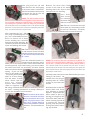
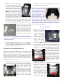
W
WARPS
ARPSC
CORP
ORP
A publication from the Yahoo Group - WarpsCorp. Providing
solutions to problems, answers to questions and ideas to share
among the amateur Astro community. We welcome you at:
http://groups.yahoo.com/group/WarpsCorp/
®
Installation Instructions for Meade
LXD55 / 75 Belt Drive Conversion &
Motor Gear Box Tune-Up
MOUNTS & DRIVES
TIPS & TRICKS SERIES
FEBRUARY 2007
WARPSDRIVE
There has been much discussion regarding loose gears, setscrews, rubber-banding and inconsistencies in the
tracking and go-to capabilities of some LXD55 / 75 mounts.
This modification kit will provide the parts needed to replace the final section of the gear train - the motor and worm
gear with precision toothed pulleys and Kevlar timing belts to eliminate any gear slop in the final drive stage and
greatly reduce the “rubber-banding” effect. Since it requires some dissassemblu of the motor units, It also includes
photos and instructions for cleaning and re-lubing of the Motor Gear Boxes and adjustment of the worm.
In general, the mount just seems to behave and perform better with this modification. The end result is a completely
reversible modification that fits within the standard motor housings.
ALL MODIFICATIONS AND ENHANCEMENTS ARE DONE AT THE RISK OF THE OWNER.
Pre-Setup Check Your Inventory...
Items are packaged as follows:
Kit Contains:
1 - Medium Bag Labeled MP containing:
2 - 30 Tooth Black Pulleys - Motor Shaft
1 - Kevlar Toothed Timing Belt
o
o
o
o
o
o
o
o
o
o
o
o
2
2
2
6
2
8
4
2
1
1
1
2
-
30 Tooth Motor Shaft Pulleys
32 Tooth Worm Shaft Pulleys
Long 4-40 Stainless Set Screws
Medium 4-40 Stainless Set Screws
Toothed Belts
Stainless Steel Allen Motor Housing screws
Button Head or Beveled Motor Case Screws
Flat wooden popscicle stick
Allen .050 wrench for set screws
Allen 3/32 wrench for 8 stainless screws
Allen 2mm wrench to fit button screws
Popscicle Sticks
Tip: Use the above check
boxes to verify and
identify the individual
parts. Keep the parts in a
tray or on a cloth covered
surface so that the tiny set
screws can not roll off of
your work surface and out
of your work space
1 - Large plastic bag labeled WarpsDrive containing:
1 - Medium Bag Labeled WP containing:
2 - 32 Tooth Black Pulleys - Worm Shaft
1 - Kevlar Toothed Timing Belt
1 - Small bag labeled MP-1 containing:
4 - Short Stainless Steel Set Screw
1 - Allen wrench (.050) for all set screws
1 - Small bag labeled WP-1 containing:
2 - Short Stainless Steel Set Screw
2 - Long Stainless Steel Set Screw
1 - Small bag labeled MC or MC-A containing:
4 - Buttonhead Steel Screws (MC)
4 - Beveled Steel Screws (MC-A)
1 - Allen Wrench (2mm)
1 - Small bag labeled MH containing:
8 - Black Coated Stainless Steel Screws
1 - Allen wrench (3/32)
1
Additional Items you will need:
o
3/16” Allen wrench to loosen screw holding RA
motor assembly to mount.
o
5/32” Allen wrench to loosen screw holding DEC
motor assembly to mount.
o
o
1.5mm Allen wrench to loosen the 4 screws
holding motor housing to motors.
Small Phillips head screw driver
to fit the 4 screws holding the
black motor housings together.
o
1 - 2 hours time and patience.
o
Cleaning alcohol, cotton swabs,
etc.
o
Optional Tools
Small towel or pad on which to work.
Procedure - Set Up:
o
Read entire directions BEFORE starting)
o
Move the mount to a comfortable position next to
your work space - make yourself comfortable - the
conversion takes about 1 - 2 hours depending upon
your comfort level with tools and experience. Verify
that you have all the partsneeded as listed above.
Lay them out on the table so you are not hunting
for them during the conversion. Some of the parts
are very tiny.
Tip: A borrowed muffin pan from your wife's pantry makes a
good parts sorting bin while you are working.
o
Disconnect all power from the mount.
o
Unplug all connections at the LXD control panel on
the RA Drive.
o
Remove the OTA and dovetail from the mount.
o
Remove the Counterweights and Counterweight
Shaft from the mount.
o
Loosen the DEC and RA Locks - Put the mount in
Polar Home Position.
Note: Now would be a good time to test / adjust your worm
toalignment to minimize slop and play and to clean them of
the stock grease. Re-lube with a high quality lubricant. This
is a tedious adjustment but one of the most rewarding when
it comes to tracking, slewing, go-to's, etc.
Adjusting The Worm:
After removing the motors, remove the worm
housings from the mount
by unscrewing the center
of the three screws
shown in the picture.
There are also two screws
accessable from the top
of the saddle.
Pull
Shim
Pull
Pull
Push
Push
Shim
Brass
Nut
Note: The three screws pictured final adjustments for alignment of the worm.The center bolt screws into the mount to
pull the worm against the worm gear. The two outer bolts
adjust the angle of the worm. Ideally, the center axis of the
worm shaft should be tangent to the circumference of the
worm. Do NOT touch these bolts while removing the worm
housing as they are adjusted from the factory. Only after
reinstalling the worm housing to the mount should you make
fine tune adjustments with the two outer bolts to adjust the
“tilt” of the worm relative to the worm gear. The two outer
bolts work in a push-pull arrangement with the center bolt.
Tightening the two upper bolts will pull the worm housing
slightly upward which will also tighten the worm against the
gear. I found that a thin shim washer of nylon or brass over
these two upper bolts between the saddle and worm housing
aided in fine tuning this adjustment.
This is a picture of a stock worm in it’s housing. The
large brass nut on the end opposite the gear is for adjusting the amount of
“play” of the worm. Removing this nut exposes a threaded
sleeve which holds the
worm in place. Adjusting the inner sleeve will
be the critical adjustment. The worm does NOT have to “spin” freely - just
turn in a smooth non-binding motion.
If properly adjusted, you should be able to grab the top
of the mount (saddle) and feel no movement if you try
to twist the mount around the RA or DEC axis.
Clean out the stock sticky grease and re-lube with
Lubriplate or SuperLube. You should be able to hand
turn the gear (or pulley) on the end of the
worm shaft with a
smooth non-binding
feel. When the gear
moves, the mount
should move - no slop
- no loose movement.
2
Dissassembly Of The RA Motor Housing:
Dissassembly Of The DEC Motor Housing:
This is the hardest part of the conversion, so once you
get through this - you are home free.
o
Looking from the top of the mount, use the small
Phillips screw driver to loosen each of the 4 screws
down inside the
Loosen These
holes near each
corner of the black
plastic
motor
housing.
This
Holds The
should release the Motor Release
Worm Block
Screw
bottom half of the
housing - carefully
remove it (being
careful of the
Loosen These
delicate encoder)
and set it aside.
Loosen These
Carefully loop the coiled cable up over the mount
out of the way in a manner which will not stress
the delicate connections to the motor controller
board.
o
Using the Allen wrench,
loosen the 4 button head
screws
which
are
recessed in the 4 holes
centrally located in the
top half of the black
plastic motor housing. Buttenhead
This will release the
Screws
upper half of the b l a c k
plastic motor housing
from the motor. Set the
cover aside. You now
have a bare motor
assembly still attached to
the mount by the one
large Allen bolt visible from the top of the mount.
o
Using a 3/16” Allen wrench, insert in the hole at
the rear of your mount - just above T-Handle ALT
adjustment bolt and engage the bolt which holds
the RA Motor Assembly to the mount. Remove the
screw as you hold the motor housing in place with
your other hand. As soon
as it releases, place the
motor housing on the
table in front of you with
DEC Drive
the control panel facin
down.
o
Using the small Phillips
screw driver, insert in RA Drive
the four holes in each
corner of the black
plastic motor housing and gently unscrew the 4 tiny
screws which hold the top and bottom halves of the
black motor housing together (DEC drive pictured
here - RA drive disassembles in the same
manner). Once loose, separate the two halves
being careful not to strain any wire connections.
Note the positioning of internal wire and the choke
for reassembly later.
Rest the motor on the table being EXTREMELY
careful NOT to touch the now exposed very delicate
encoder wheel at the end of the motor opposite the
gear. Do NOT touch it or allow it to contact the
table or work surface. Using a 1.5mmAllen wrench,
remove the 4 small
button
screws
holding the black
plastic motor case
to the motor. Set
this motor case to
the side. You now
have
a
fully
exposed
LXD55
/
Encoder Wheel
75
motor.
Extremely Fragile
o
o
Using the .050 Allen wrench loosen the set screw
in the gear and gently pull the gear off of the shaft.
Clean the shaft if has any left over thread locker
adhering to it using some fine sandpaper, steel wool,
x-acto knife - whatever it takes. Wipe the shaft off
with some alcohol to remove any oils or residues.
Using the .050 Allen wrench, loosen the set screw
on the motor gear and remove
Gear Removed
the gear from the shaft. Clean
WarpsDrive Screws Installed
the shaft as you have did
previously on the RA assembly.
Manually turn the gear on the
DEC wormto check for slop
and excess play. Now is a good
time to clean and adjust as
previously described. If you
aresatisfied with the worm's adjustment, proceed.
o
There are two different screw replacement sets. There
are the standard button-head screws in bag MC and
the zero-clearance screws in MC-A.
Note: Now is the time to do the Motor Gear Box Tune-Up if you plan on doing so. Or you can proceed to the DEC motor
dissassembly and do the gear box tuneup when both motors are removed from their mounts.
3
Replacing The Motor Block Screws:
This next procedure will be repeated for both the
DEC and RA motor assembly.
o
Looking at the motor
block without the gear,
you will notice there are
Remove These
3 black Allen head
screws protruding from
the motor block. The
two closest to the
motor shaft (covered by
the gear you just
removed) will have to be
replaced with the button head or beveled screws
included in the kit to allow for tighter clearance to
allow the new converted drive to fit inside the stock
black plastic motor housing.
Note: If you are doing the Motor Gear Box Tune-Up, perform
the following three steps after you have removed the motor
from the block
o
Remove all three of the original black screws
holding the motor into its mounting block. Very
carefully push the motor slightly back in its
block until the protruding motor shaft is flush with
the front of the block. Be
careful of putting any strain
on the electrical wiring.
o
Holding the motor upside
down so that the motor shaft
and screw holes are facing
downward, carefully drill out
the two inner holes with the
bevel bit. The metal is soft
and very little pressure is
needed. When you finish, the beveled holes should
look like the ones in the picture. Test fit the screws
to be sure you have gone deep enough with the bit.
Note: Now is the time to do the Motor Gear Box Tune-Up if
you plan on doing so before replacing the screws. Resume
the re-assembly at this point after you finish the Motor Gear
Box Tune-Up.
o
o
Using the 3/32” Allen
wrench (from the MH
bag, remove (one at a
time) the two screws
closest to the motor
shaft and replace with
the button head screws
using the 2mm wrench
from the MC bag.
Bevel-Head Screws
Bag MC-A
Button-Head Screws
Bag MC
Repeat this procedure for the remaining drive
using the remaining two button head screws from
the MC bag.
Zero Clearance Modification:
o
Shake and blow
out any shavings that
may have gotten
through to the inside
and then reassemble
the block with the
new screws.
The new beveled screws should be
flush or just slightly countersunk
below the surface of the
mounting block as pictured.
Progress Summary:
o
If you want to gain an extra 1/16” clearance
between the pulley and the motor housing, you can
use the four stainless steel bevel head screws
which are included the kit bag MC-A.
At this point, you should now have
two motor assemblies that are ready for their pulleys
and to be mounted back onto the mount. You should
have already completed:
o
To use the beveled screws,
you will need a countersink
/ beveled bit like the one
pictured here. They are
available at most major
hardware stores for around
$4.00.
o
Motor Gear Box Tune-Up.
o
Replacement of the motor mounting screws.
o
Worm cleaning, re-lubing and adjustment.
o
Adjustment of the worm to the worm gear.
Buy cheap as you only need it
for four holes.
If you are ready to remount the motors and pulleys,
please proceed to Page 9.
4
Note: This procedure can be done with the encoder in place - if you are
careful. Removing the encoder requires a very tiny 0.9mm allen wrench
and the tiny set screw is easily stripped. If you try to remove it - proceed
with extreme patience and care.
Motor Gear Box Tune-Up:
Setup / Tool Check...
Tools You Will Need:
o
o
o
o
o
o
o
o
o
o
o
o
o
o
o
o
Assorted Allen Wrenches (see pictures)
Small Phillip’s Screwdriver
Wire Cutters / Sharp Scissors
Toothpicks
Tweezers
Single Edge Razorblade
Lubricating Grease
Application Paddles (wood coffee stirrers)
1 - .050 Allen wrench for set screws
1 - 3/32” Allen Wrench
Shallow Dish and Fresh Turpentine
Old Toothbrush
Q-Tips
Ultra Flat Black Paint (optional)
Red Felt Tip Marker
Shrink Tubing / Electrical Tape
These are the wrenches that I regularly use in
working on my mounts. The ball-ended Allen wrenches
are available at Home Depot for about $19.00 a set.
They are made by Husky and include the following sizes:
Metric: 1.5, 2, 2.5, 3, 4, 4.5, 5, 5.5, 6, 7, 8, 9, 10
Here you see the bare motor assembly removed from
it's plastic housing. Notice the delicate encoder (shiny
slotted disc on the left end of the motor). It is absolutely essential that this wheel be straight, clean, tight
on the shaft and
nearly centered
with the emitter
and the receiver.
Centering does
not have to be
absolute - just be
sure it is not
bent or rubbing
against either of
the emitter or the
receiver.
The white wire
block at the upper left appears to be a removable plug
- it is not. Do not pull or try to pry it loose from the
board.
Caution: Caution: do NOT touch the encoder disc with your fingers as you
will leave an oil residue which will attract dust and pollen in the air. If you
do touch it, clean it with a very soft, fine brush and denatured alcohol or
acetone.
SAE.050,1/16, 5/64, 3/32, 7/64, 1/8, 9/64, 5/32, 3/16, 7/32, 1/4, 5/16, 3/8
The ball end seems to offer a
much better grip on some of
the tiny set screws used in this
mount.
It has easily
removed and tightened
setscrews that other normal
wrenches seem to just spin
in. Highly recommended.
Another set of micro
wrenches that I find
indespensible when
working with these
mounts and their
many tiny set screws.
GOOD ENCODER POSITIONING
WITH 0.9MM ALLEN KEY
This is a picture of my finished motor assembly with
replacement encoders that have been painted with several very light mist coats of Krylon Ultra Flat Black.
The replacement encoders are available from:
http://www.lxd55.com/order/encoders/
5
TThe plug with the red and
black wires are the wires going
to the motor and is removable.
Note the orientation of the wires
and mark the pin for the red
wire with a red marker.
Caution: This small controller board has
several integrated circuits on it and is therefore succeptable to damage due to static discharge. I recommend touching something that is grounded to drain any charge from yourself each
time you sit down to work on or handle the board. In 40+ years of handling
electronics, I've never had a piece of electronics damaged by static electricity - but you don't want this to be the first time.
Remove the three allen head
screws on the end of the motor
housing where the "keyed" shaft
emerges from the housing.
Once these
three screws
are removed,
the motor will
slide out of the housing.
Note: Take note of how the wires are routed
and be careful not to stress them as you slide
the motor out of the housing. The encoder
can be with a very tiny 0.9mm Allen wrench to loosen the set screw.
After removing the red / black
wire plug and marking the red
pin, use a small Phillip's screwdriver to remove the 4 shiny
screws holding the controller
board to the motor housing. Be
careful so you don't slip off of the
screw and damage the board.
Note: There are 4 very small nylon spacers under the board on each screw which
holds the board away from the motor housing. Be careful not to drop and loose these
tiny spacers.
Once the controller board is removed from the housing, take a
small pair of wire snips or wire cutters and cut the two
wires as pictured. If you look closely, you can see where
the wires have been cut previously and then spliced
and covered with shrink
tubing. If you cut and
splice in this same area
- everything will look the
same as a stock setup.
You will notice a small
metal "donut" that the
wires are wrapped
around. This is a ferrite
choke to suppress any
RF energy emisiions which may be emitted by the motor wires - causing interference in nearby radios/tv's
or even the AutoStar hand controller.
Note: Since I did not see the need for
this choke, I removed the ferrite donut
and thus shortened the wires considerably. Running the motors in house
next to my TV, computer, wireless lan
and and stereo exhibited no unwanted
interference. This option would be your
call.
Caution: The connections of the wires to the motor are very delicate. Do
not pull or put un-neccessary strain on these wires. If you do happen to
pull one loose - it probably can be fixed by carefully soldering it back to
one of the tabs visible from the encoder end of the motor. A wrap of
electrical tape around the end of the motor holding the wires against the
motor body will keep the wires tucked against the motor and remove the
opportunity for excess stress.
Carefully remove the two screws that hold the gear cover
casing to the motor. Be
careful not to let the gear
housing come off - hold it
in place as you remove the
screws.
Hold the motor so that the
motor shaft and shiny
gear housing is pointed
upward. As you hold the
motor shaft in place by
placing your finger on the
end of the shaft, slide the
motor housing up and off
to expose the internal
gearing. Note the position
of the gears before removing any of them.
6
REMOVING THE GEARS...
Once the gears are exposed,
grasp the larger "keyed" motor
shaft and lift it out of the housing. Be careful as there is a
washer/bearing sitting directly
on top of the large black gear
and there is a very tiny little
washer that goes over the small
spindle at the bottom of the
shaft. The gear itself is attached
to the shaft and does not move.
THE MAIN KEYED GEAR AFTER IT IS REMOVED FROM THE
HOUSING. BE CAREFUL NOT TO LOOSE THE TWO WASHERBEARINGS AS PICTURED BELOW.
THE INTERNAL GEAR CLUSTER SHOWING THE STOCK STICKY
GREASE AND LOTS OF PLASTIC DEBRIS
This washer sits on top
of the plastic gear.
Main Keyed Shaft
Upper Shaft
Brass Bushing
This washer fits over
small pin at bottom of
shaft..
Lower Shaft
7
Remove the large black gear from the lower shaft.
MAIN SHAFT REMOVED. THE OTHER TWO SHAFTS DO NOT
COME OUT - THE GEARS SLIP OVER THE SHAFTS.
Remove the large black
gear from the upper shaft.
LARGE GEAR FROM UPPER SHAFT
LARGE GEAR & BRASS BUSHING FROM
LOWER SHAFT
Remove the small brass bushing / bearing from the
lower shaft.
Remove the small white gear from the shaft.
Note: Directly under the brass bushing is another small washer between
the brass bearing and the gear face.
The small pinion gear on the
motor shaft does not come off.
BRASS BUSHING FROM
LOWER SHAFT
8
CLEANING THE GEARS...
I used a white (easy to see small
washers that drop off of the
shafts and gears while cleaning)
cool whip container (cause I like
cool whip) with about 3/4" of
fresh turpentine (mineral spirits
will also work) and an old toothbrush to clean the sticky original grease from the gears.
Once cleaned, it's time to re-lube and re-install the gears
in the reverse order of removal.
I've tried several different
lubricants and had settled on
white lithium grease but change
happens and I have now
changed
my
"preferred"
lubrication to SuperLube. It is
100% synthetic, clear, resists
water, has PTFE particle
suspension, does not run and
is super slick.
Once you have the gears lubed up and back in place,
carefully put the gear casing back in place and tighten
down the two screws holding it in place. Carefully turn
the encoder end of the shaft a couple of times to
ensure you have nothing binding and smooth rotation.
(
I touched the two bare ended motor windings to a AA
battery to allow the motor to turn a few rotations
reverse the wires to rotate it in the opposite direction and confirmed all was operating as it should).
REASSEMBLE THE MOTORS...
Follow the directions in reverse till you have the motor
mounted back inside the housing. Solder the
conections to the motor wires, remount the controller
board (don't forget the spacers under the board), plug
the two red/black wire plug back in place with the red
wire towards the middle of the board (away from the
encoder) and you are finished.
Enjoy Smoother - Quieter motoring!
You can read more about here:
http://www.super-lube.com/product_description.htm
I purchased mine from:
http://precisionreloading.com/superlube.htm
Note: In its out of the tube or tub form,
SuperLube is extremely good - although a
little "stiff". In my mounts, I made my own
custom formulation by filling a shot glass
almost to the rim with the SuperLube and
then adding about 3/4 of a cap of 100% pure
synthetic motor oil (Mobile 1, Penzoil, etc just make sure it is NOT a blend but 100%
synthetic). Mixing this up gave me a very
nice viscosity which gave super smooth buttery like movement in all parts of my mount with no running and no breakdown.
Re-assemble the gear box in reverse order adding
lubricant to each shaft, each washer/ bearing, each
gear face all gear teeth. Make sure to put a large dab
on the end of each shaft, on the inside of the gear
housing where the indents are to hold the gears and
on the motor pinion gear. I was not afraid to use a lot
of lube as the gear box is pretty much sealed and the
SuperLube does not run - I covered the whole gear
cluster with lube.
DRIVE GEARS REPLACED WITH
WARPSDRIVE BELT CONVERSION TIMING PULLEYS
BEFORE CONVERSION
AFTER CONVERSION
9
Assemble The Pulleys:
At this point, you should have completed any
mechanical adjustment, cleaning, re-lubing or other
items you want to accomplish. These steps will mount
the pulleys and re-assemble the motors to the mount.
Repeat these steps for both motors and both worms.
o
Take one of the 2 smaller pulleys from bag MP and
remove the standard black set screws using the
.050 wrench from bag MP-1.
o
Take 2 of the 4 short set screws from bag MP-1 and
carefully thread it into each of the holes in the
pulley.
Press the pulley onto the
motor shaft getting it as
close to the motor body as
possible without it
rubbing on the two button
head screws you just
replaced in the motor
body.I used a business
card as a “guage” in between the pulley and the
head to set my spacing. If you have a set of feeler
guages, you can use the thinnest one that will
prevent the pulley from
touching the head of the
button head screw. Tighten
the remaining set screws
against the motor shaft. Do
not over tighten so as to strip
out the set screw head remember, you now have 2
set screws holding the pulley to the shaft.
o
o
If you haven’t already, using the .050 Allen wrench,
loosen the set screw on the worm gear shaft,
remove it and clean the shaft as you did with the
motor shaft. Wipe with alcohol to remove any oils
or residue.
o
Take one of the 2 larger pulleys from bag WP and
remove the standard black set screws using the
.050 wrench from bag MP-1.
o
Take 1 of the 2 short set screws and 1 of the 2 long
set screws from bag WP-1 and carefully thread it
into each of the holes in the pulley.
o
Press the pulley on to the worm shaft lining up the
long set screw with the flat area of the shaft. Tighten
the long set screw and then the short set screw.
You now have installed 2 black motor pulleys each with
2 new short knurled cup point stainless steel set
screws installed and 2 black worm pulleys (pictured
yellow in the photos as it was a prototype) with 1 short
and 1 long knurled cup
point stainless steel set
screw installed. These new
screws will provide a better
grip on the shaft and the
serations in the cup are
designed to resist conter
clockwise rotation. They
should virtually eliminate the
“loose set screw” problem which occurs in these
mounts.And to further decrease the opportunity for a
pully to come loose there are now two set screws per
pulley.
Note: Refer to the photos to check for the overhang of the
worm pulley past the end of worm shaft. In the photos, the
yellow pulley is the worm pulley (prototype photo). The worm
shaft will be slightly recessed into the worm pulley to allow
for better alignment between the two pulleys once they are
remounted to the mount. Some experimentation may be
needed with trial and error fittings to get the best alignment
without the pulley rubbing against the black motor housing.
Alignment does NOT have to be perfect in that the belts
doallow for a small degree of error and flexing.
Re-Assembly Of Motors To The Mount:
RA Motor Re-Assembly (Option 1):
Note: Read Option 2 Before Proceding
o
Be careful of the delicate encoder wheel: Place the
half of the black plastic motor housing (without the
control panel) on top of the motor and attach with
4 of the 8 supplied Allen screws (bag MH) using the
included Allen wrench.
o
Place a toothed belt over th motor pulley.
o
Making sure that the belt
is hanging loose and not
binding,assemble the
bottom half of the black
plastic housing by lining
up the 4 screw channels
and retightening the 4 self
tapping screws (that you
Self Tapping Phillips Screws
previously removed) in
each corner using the small Phillips screwdriver.
Note: Do NOT overtighten these 4 screws or you could strip,
crack or break the channel.
10
o
Holding the motor housing in
one hand against the mount,
re-thread the large Allen bolt
you previously loosened from
the back of the mount to secure
the housing to the mount. Do
NOT tighten, just have it tight
enough to hold the motor
housing from falling off. While
gently lifting up on the motor
housing with one hand, use
the popscicle stick or other blunt tool of your choice
to lift the belt up and over the worm pulley. This
may be tight. Lifting, fiddling with the position of
the motor housing will aid in giving you some slack.
Once the belt is over both
pulleys, pull downward on
the motor housing with one
hand (to take up any excess
slack in the belt) while you
tighten the large Allen bolt to
firmly secure the motor assembly to the mount.
with open access for installing the belt and
making tension adjustments.
Note: The shiny foil that you
see in the picture are small
strips of DynaMat. This is a
self adhesive sound and vibration dampening material
that is used extensively in the
car audio business. As in
these other pictures, you can
see that I have lined all of my
motor housings with the
DynaMat which helps to reduce vibration and motor noise
and then spray painted them with Krylon Ultra Flat Black Spray
Paint. If you can not find a local car audio dealer that handles
it, you can buy if directly from:
http://www.dynamat.com
o
Note: A slight “twisting” pressure on the motor housing will aid in taking up slack. The belt
does not have to be absolutely tight - you want just a very
slight amount of slack.
o
Visually inspect through the access "porthole"
for any rubbing or binding areas. Take a breather
- have a cold drink and move on to the next step for
the DEC motor - a piece of cake.
RA Motor Re-Assembly (Option 2):
This option may seem a bit drastic, but is really quite
simple and will make the installation of the RA Belt
Drive and Adjustment extremely easy and precise.
While it is NOT reversible, it is invisible and will not
affect the mount should you decide to go back to the
standard gear drive. You will need a small hacksaw or
hacksaw blade or a dremel tool.
With the RA Motor removed at the mount, take the
hacksaw blade and cut a notch in each of the lower
corners of the RA mounting
plate. Note position and
depth of the notches. This
will allow access to the small
DynaMat
Phillips screws that hold the
top and bottom of the black
housing together, allowing
Notch
Notch you to mount the motor
while it is in the housing
o
Be careful of the
delicate encoder
wheel: Place the half
of the black plastic
motor
housing
(without the control
panel) on top of the
motor and attach
Replace These Screws
with 4 of the 8
supplied
Allen
screws (bag MH) using the included Allen wrench.
You now have the motor mounted inside of the
black plastic housing - ready to be mounted onto
the mount. Holding this assembly in one hand,
position it on the mounting
plate (the plate you just cut
the corner notches into) and
insert the large allen bolt
into the hole just above the
T-Handle and tighten it just
enough to thread into the
motor block to hold the
assembly in place. Do not
tighten at this time.
ASSEMBLY IN POSITION
o Check the pulleys for alignment and make any
adjustments necessary.
Carefully install the
remaining belt over the
two pulleys. As you
tighten the large Allen
bolt that holds the motor
and assembly to the
mount, you will notice
that it “pulls” the motor
closer to the worm which
o
11
could result in too
much slack in the belt.
Popsicle Shim
At this point you can
place a shim or spacer
between the motor and
the mount to adjust the
spacing. I used a small
length of one of the
popsicle sticks as a
shim between the motor and the mount to tighten
up the belt. You do not want the belt too tight, it
should have just a bit of flex. Once you get the
desired spacing, tighten down the large Allen bolt
to hold the assembly in place.
o
Note: You may have to start in on one
side of the motor pulley and then turn
turn it to wrap it around the pulley - kinda like replacing a
bicycle chain in your younger days. Once the belt is in place,
slide it back and forth to take up any excess slack in the belt
while tightening the large Allen bolt to secure the motor assembly. Don't make the belt too tight - just not sloppy.
Note: I placed a large split washer over the large Allen bolt
before installing it. This allows me to make fine tune adjustments on the belt tension just by slightly loosening or snugging up the bolt.
o
Assemble the remaining top half of the motor mount
with the AutoStar Control Panel to the motor using
the original 4 self tapping screws. You can access
their mounting holes from under the mount using
a short Phillips screw driver. Line up the screw
channels (posts) and carefully tighten the screws
once you have the assembly lined up and are sure
there are no binding or pinched wires.
Install These 4 Screws To
Secure Top Half of Cover
Carefully line up and
the bottom half of the
motor housing (making
sure
the
rubber
Install These 4 Screws To
grommet on the cable
Mount Bottom Half of Cover
is seated in the indent)
and secure with the 4
self tapping screws
using a small Phillips
head screwdriver. Do NOT overtighten as this could
crack or break the screw channels.
o
Visually check for any areas that might be binding
or rubbing.
DEC Motor Re-Assembly:
o
The appropriate pulleys
should already be mounted
on the DEC motor shaft
and DEC worm assembly
Mount the DEC motor to
the mount with the large
Allen bolt visible at the top
of the saddle plate. Do not
tighten all the way as this bolt is also used to
adjust the final tension on the belt once installed.
Be very careful not to touch or damage the delicate
encoder wheel.
Note: The Captive Bolt holes
shown in this photo is a modification detailed in another Tips
DEC Motor
& Tricks Guide to offer a more
Mounting Bolt
Captive Bolt
secure and rigid mating of the
For Dovetail
saddle plate (dovetail) to the
saddle which improves the rigidity of the mount.
o Using the 4 remaining
small Allen screws and the
Allen wrench (bag MH),
reattach the upper half of
the black plastic motor
housing to the motor.
Once again, be careful of
the delicate encoder wheel.
o
This completes the
RA Motor Assembly Belt Conversion
o
Install the remaining belt over
the two pulleys. Once the belt
is in place, adjust its tension
and tighten the large allen
head bolt on the topside of the
saddle.
This completes the
DEC Motor Assembly Belt Conversion
12
Final AutoStar Adjustments:
o
Plug in the DEC motor AutoStar and power supply.
o
Turn on power and bypass all the alignment, date
and time functions to get the Telescope menu.
o
Enter the (value) for the AutoStar drive ratios and
change the sign from (-) to (+).
Calculation for these ratios are as follow:
(multiplier) x (#worm teeth) / ( motor teeth) x (worm teeth)
LXD55/75 Motor Multiplier = 0.01666666
Worm Pulley Teeth = 32
Motor PulleyTeeth = 30
Worm Teeth = 144
This yields:
.01666666 x 32/30 x 144 = 2.559998973
WarpsCorp Enhancements:
WarpsDrive Belt Conversion:
Single Axis: $40.00 (includes shipping in US)
Dual Axis: $74.95 (includes shipping in US)
Cup-Pointed Serrated Replacement Set Screws for Stock Gears
Eliminates The Loose Gear Syndrome
4 Hardened Steel Set Scres and Wrench: $3.00
For Previous WarpsDrive Purchasers:
Set of 4 Zero Clearance Motor Screws: FREE
If you need the set screws or zero clearance screws: Send a SASE
(self addressed stamped envelope) to:
David Sherfy
199 Stoneyview Lane
St. Louis, MO 63146
The $3.00 payment should be 3 - 1 Dollar Bills inside the SASE
For Non-US customers - Email me for details.
Rounding to 6 places, I use: 2.559999
In the AutoStar menu:
Scroll to SETUP - Press Enter
Scroll to TELESCOPE - Press Enter
Scroll to AS/RA Ratio - Press Enter
Enter the number: 2.559999 and change the sign to (+)
Scroll to ALT/DEC Ratio - Press Enter
Enter the number: 2.559999 and change the sign to (-)
o
o
Perform a "Calibrate Motors" to make sure the
drives are operating properly. After the calibration,
run each drive at various speeds to check out
operation.
Highly Recommended Items of Interest:
These are items which I have found and use which I feel are worth
while to pass on to other Amatuer Astronomy Enthusiasts
RACI (Right Angle Correct Image) Finders make your viewing more
pleasurable. Here is highly recommended alternative to the popular
Orion RACI selling for $102.82 with mount & standard ground shipping.
Manish at Agena Astro Products offers an almost identical unit from GSO.
An 8x50 RACI and includes the bracket & dovetail mounting base for
$62.00 which includes shipping in the US.
That’s a savings of over $40.00.
It is available in White to better
match your Meade OTA. I use it and
found that the coatings on the Agena
product seem to be just a little
deeper in hue. Crystal clear views
with well defined crosshairs.
Adjustable focus and lens caps
are included. The adjustable
mount is a cinch to use.
Remount your OTA, perform another "Calibrate
Motor" and follow with an accurate drive training
and you should be ready to go.
This completes your belt conversion. I think you will
find that your mount has a much better “feel” and just
behaves better in all operations.
A special thanks to Mike Gray for his initial testing
and review which can be viewed at:
http://www.wideopenwest.com/~mgray8351/BeltDrive.htm
Feel free to email me if you have any questions at:
[email protected]
http://www.agenaastro.com
Manish Panjwani
16430 Debra Ln
Cerritos, CA 90703, USA
E-mail: [email protected]
Phone: 562-972-3738
13
seem to work, the color purity and
saturation of the Ink Republic inks
result in the best color - no
noticable difference from the
standard Epson cartridges and
ink. Granted, I have not tested
them for durability in the sun or
rain... but I do most of my printing, reading and displaying of
prints indoors - so it just
doesn’t matter.
Put An End To Those Printer Blues...
Another item which I came across was the result of
constant frustration when it came to printing. I have
several Epson R300 color inkjet printers which are
under constant use by my family and myself. These
new printers offer fabulous printing quality with their
multiple colors and now shades of colors. These new
printers no longer use the standard 3-color and black
cartridges, but instead
are now using 6 and
more colors /cartridges.
The problem is that they
never all run dry at the
same time and when
one goes dry... your
done. You can’t just
switch to black only
printing - you have to go
out and buy a replacement cartridge for the one color
that just went out. And to add insult to injury - the
cartridges hold about a third as much ink as they use
too. Progress?
In printing astro photos, I found that I was changing
black cartridges almost as often as I was changing
socks. At $12.00 and per cartridge, replacing all six
cartridges was starting to get a little pricey.
I recently converted to a CIS (Continous Ink System)
bulk ink configuration from Ink Republic... joy, joy!
This system consists of six individual 100ml / 3.4oz
bottles of ink connected through flexible tubing and an
ingenious cartridge system which replaces the
standard ink cartridges. The individual bottles of ink
are less than $12.00 each.
The kit also comes
with a unique little
circuit board device
that fits in the print
head / cartridge carriage just in front of
the cartridges that
“fools” the printer into
thinking that the cartridges are always half full.
Some other systems make the printer think the cartridges are full (new) which forces the printer into having to have the jets re-aligned / purged as when you
put in a new cartridge.
This wastes ink.
The Ink Republic system does not.
I’ve tried several other CIS systems and while they all
The system also worked better on my printer set up
because as you can see, I have the printer elevated on
a small platform so that the ink bottles are sitting lower
than the printer. Some of the other systems I tried,
had trouble pulling the ink from the lower level which
resulted in bubbles in the lines and gaps in the
printing. As you can see in the photos, they have self
adhesive holders to hold the feed tubing in place. (I
did cut a small notch in my printer lid to allow the
cover to close when not in
use. It was no big deal as
I just ordered a new
replacement cover from
Epson should I ever decide
to go back to the old ways
(no way unless I am
selling
the
printer).
The cost of the kit ranges
from $199.95 to $275.00 but remember this is a one
time cost and the larger ink supply costs no more than
standard cartridges. It will not take you long to save
the cost of the kit - just three changes of your
cartridges and you are there.
THE BOTTOM LINE...
This system is easy to install.
It will save you money.
It will save you time.
Print quality is virtually indisguishable from standard
Epson cartridges (in my usage).
It will end the “out of ink” frustration factor and most
importantly...
OPERATION
OF THE
INK REPUBLIC CIS SYSTEM
HAS BEEN FLAWLESS.
http://www.inkrepublic.com
14