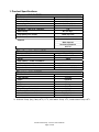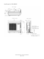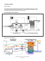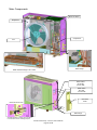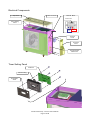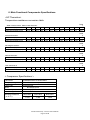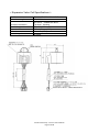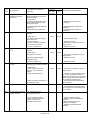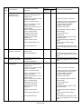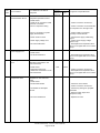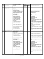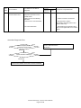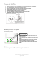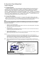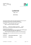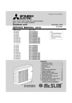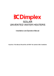
1
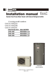
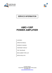
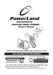
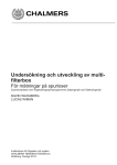
Service Technical Book GAUSͲ315EQTA HeatPumpUnitGAUͲA45HPA TankUnitGAUͲ315EQTA HeatPumpUnit GAUͲA45HPA SandenHeatPump–ServiceTechnicalBook Page1of48 TankUnit GAUͲ315EQTA Contents ͳǤ ʹǤ ͵Ǥ ͶǤ ͷǤ Ǥ Ǥ ͺǤ ͻǤ ͳͲǤ ͳͳǤ ͳʹǤ PATENTS This water heater may be protected by one or more patents or registered designs in the name of Sanden Australia Pty. Ltd. TRADE MARKS ® Registered trademark of Sanden Australia Pty. Ltd. Note: Every care has been taken to ensure accuracy in preparation of this publication. No liability can be accepted for any consequences that may arise as a result of its application. SandenHeatPump–ServiceTechnicalBook Page2of48 1. Product Specifications *1 *1 *1AmbientTemp.(Dry/Wet)16oC/17oC,InletWaterTemp.17oC, OutletWaterTemp.65oC SandenHeatPump–ServiceTechnicalBook Page3of48 2. Dimension Outlines Hot Water Storage Tank unit GAU-315EQTA SandenHeatPump–ServiceTechnicalBook Page4of48 HeatPumpUnitGAUͲA45HPA SandenHeatPump–ServiceTechnicalBook Page5of48 3. System Details How it works The Heat Pump Water Heater System heats water by transferring the heat from the surrounding air to the water using a refrigerant. The refrigerant is heated by a heat exchanger that absorbs heat from the surrounding air. Heat Pump Water Heater System Heat pump unit Tank unit (hot water storage) System Circuit Diagram SandenHeatPump–ServiceTechnicalBook Page6of48 4. Basic Control Logic Specifications HP unit operates to achieve the target heat capability 4.5kW to output 65oC (fixed) water once the power is on. Conditions to start and end heating water are as stated below: Conditions to (1) Tank TH A 45 oC (Lack in residual hot water in tank) Start Operation (2) More than 24hrs passed since the last start of operation. (for anti-Legionella purpose) (3) Memory of last operation is lost. (First run after delivery, ROM writing error, etc.) (4) Electrical shutdown is occurred while HP unit is operating. (5) The current time is 10.00 (24hr clock basis). (6) HP unit was not operated by the condition (5) due to a limitation of HPU operation. HPU operation starts once the limitation is cancelled. The term limitation defines a condition where HPU cannot be operated due to the electricity cutoff or the blockout time setting. Condition to End HP unit starts when either of (1), (2), (3), (4), (5) or (6) above is satisfied. GC Inlet TH > 50oC However, operation will not be performed during the time set as the blockout time on the timer setting panel. Freeze Prevention Drive To avoid fracture in freezing, HP unit starts heating water when the pipes get below the specific temperature while Driving Mode is on (including hours set as blockout time). Operation HP unit starts operation when either GC Inlet TH or Outlet TH detects 5oC or less. It will not start if the mode is set to the Off Mode. When Driving Mode is on (including hours in blockout time) Target Heat Capability: 4.5kW Condition for Ending Freeze Prevention Drive: GC Inlet TH > 50oC If the condition meets to that to heat water during the freeze prevention drive, the operation shifts to water heating operation. Air Exhaust Operation If Tank TH A 30oC at the start of water heating, HP unit runs the pump for 3min by 2.5L/min before starting to heat water. If Tank TH A > 30oC, the pump does not run before operation. SandenHeatPump–ServiceTechnicalBook Page7of48 Defrost Start of defrost is determined by the temperatures detected by Defrost TH and Inlet Air TH. If the condition meets one of the determination values, HP unit starts defrost drive. However, the defrost drive is cancelled for 12min after the compressor runs or 30min after defrost drive completes. Also, if GC Inlet TH > 32oC, defrost drive does not start. End of defrost is determined either by the temperature detected by Defrost TH or by the time passed after start. Defrost drive stops when the condition meets one of the determination values. Times of Retries at Error Occurrence Number of times to retry recovery when an error is detected is increased from 5 times to 7 times as a countermeasure for the electrical testing. SandenHeatPump–ServiceTechnicalBook Page8of48 5. Main Functional Components List HeatPumpUnit No. 1 2 3 4 5 6 7 8 9 10 11 12 13 14 15 PartName COMPRESSOR8CS040XAA63 PRESSURESWITCHCCBͲDB10CE EVAPORATOR5A GASCOOLER PCBA45HPA SETTINGPANELASM.A OͲRINGP14FP29 PROPELLERFANHP HPTHERMISTORPT2MͲM51FͲS2 EXVALVECOILUKVͲA12VͲB PC28L05 FANMOTORSICͲ65FVͲF515 DRAINPLUGPPS OͲRINGP3FP29 REACTORTSN61 Remarks Compressor Pressureswitch Airheatexchanger Waterheatexchanger Printedcircuitboard Timersettingpanel OͲringforwaterpump Propellerfanblade Heatpumpcontrolthermistor Pin1,2:Waterinlettemperature Pin3,4:Wateroutlettemperature Pin5,6:Ambienttemperature Pin7,8:Refrigerantdischargetemperature Pin9,10:Defrostcontrol Expansionvalvecoil Watercirculationpump Fanmotor Drainplug OͲringforDrainplug Reactorforinverter Qtty. 1 1 1 1 1 1 2 1 1 1 1 1 2 2 1 HotWaterStorageTankunit No. PartName 1 TANKTHERMISTOR Remarks Tankthermistor SandenHeatPump–ServiceTechnicalBook Page9of48 Qtty. 1 Main Components Main PC Board Evaporator Compressor Fan Water Heat Exchanger –GC cooler Water Pump Water Valve GC Outlet ½ inch male Water Valve GC Inlet ½ inch male Connector Cover Detachable Water Filter Drain Plugs Supplies filtration for water going into HPU. It can be taken off for cleaning purpose. SandenHeatPump–ServiceTechnicalBook Page10of48 Electrical Components Main PC Board Top Cover Terminal Block 3 x M4 Screws Timer Setting Panel Power Supply Earth Terminal Cover Connector Cover Tank Thermistor Cable Hose Timer Setting Panel PC Board Panel Housing Front Bezel Sheet SandenHeatPump–ServiceTechnicalBook Page11of48 6. Main Functional Components Specifications <HP Thermistor> Temperature-resistance conversion table Water inlet thermistor, Water outlet thermistor Temperature ( ) -10 0 10 Thermistor resistance (kȍ) Table 1 20 37.5 23.7 15.5 10.3 30 40 50 60 70 80 90 100 7.0 4.9 3.5 2.5 1.9 1.4 1.1 0.8 Table 2 Ambient thermistor Temperature ( ) -10 Thermistor resistance (kȍ) 12.0 7.20 4.45 2.83 0 10 20 30 40 50 60 70 80 90 100 1.85 1.24 0.84 0.59 0.42 0.31 0.23 0.17 Table 3 Discharge thermistor Temperature ( ) -10 0 Thermistor resistance (kȍ) 276 162 10 20 98.3 61.5 30 40 50 60 70 80 90 100 39.5 26.1 17.6 12.1 8.54 6.12 4.46 3.30 Table 4 Defrost thermistor Temperature ( ) -10 Thermistor resistance (kȍ) 9.39 6.00 3.94 2.64 0 10 20 30 40 50 60 70 80 90 100 1.82 1.27 0.91 0.66 0.49 0.37 0.28 0.22 Table 5 Tank thermistor A Temperature ( ) -10 Thermistor resistance (kȍ) 54.6 32.4 19.9 12.5 0 10 20 30 40 50 60 70 80 90 100 8.1 5.3 3.6 2.5 1.8 1.3 0.9 0.7 < Compressor Specifications > Part Name Compressor type Pump type Motor Rated output Insulation grade COMPRESSOR 8CS040XAA63 Hermetic motor compressor Involute scroll Brushless motor 1.8 kW B Grade Winding resistance ( at 20 ) RED-WHT WHT-BLU BLU-RED 1.434 1.434 1.434 SandenHeatPump–ServiceTechnicalBook Page12of48 < Expansion Valve Coil Specifications > Part Name Dielectric strenght EX VALVE COIL UKV-A12V-B AC 1800V 1sec. Insulation resistance Rated voltage Current Coil resistance Insulation grade DC 500 V , 100Mȍ OR More Terminal - Housing DC 12V ± 10% 0.26 A / Phase (20 ) 46 ± 3 ȍ (20 ) E Grade SandenHeatPump–ServiceTechnicalBook Page13of48 < Water Circulation Pump Specifications > Part Name Pump type PC28L05 DC driver operation , Variable flow performance Coupling Caliber inlet / outlet Motor type Bearing type Direction of rotation Operating position Driving power supply : Vm Driving MAX voltage Flow variable system Insulation grade Fluid temperature Outer diameter ij27, Inside diameter ij18 (Quick fastener type) DC brushless motor Underwater slide shaft CCW Impeller shaft horizontal 282V [DC] +40% / -10% (254 395V [DC] ) Below 450V Variable rotation rate by PWM E Grade ( Winding temperature 115 below ) 3 65 SandenHeatPump–ServiceTechnicalBook Page14of48 7. Maintenance The procedures to replace the functional components are shown in the following pages. Since this product utilises a high-pressurised gas (CO2), those components contained in the refrigerant circuit such as refrigerant pipes, heat exchanger, compressor, pressure switch, are not subject for replacement. 1) 2) 3) 4) 5) 6) 7) 8) How to Replace Printed Circuit Board How to Replace Timer Setting Panel How to Replace Water Circulation Pump and its P14 O-Rings How to Replace Propeller Fan Blade and Fan Motor How to Replace Thermistors How to Replace Expansion Valve Coil How to Replace Drain Plugs and P3 O-Rings How to Replace Reactor SandenHeatPump–ServiceTechnicalBook Page15of48 1) How to Replace Printed Circuit Board RemoveTopPanelandFrontPanelRetainer (6screws) RemoveFrontPanel (5screws) RemovePipingCover (1screw) RemoveTerminalBlockCover. (1screw) UnscrewTerminalBlock (2screws) RemoveCaseReinforcement(PS) RemoveControllerCaseCover (1screw) SandenHeatPump–ServiceTechnicalBook Page16of48 Unplugallthenecessarycable connectorsandremovetheearth screws(5screws). RemovescrewsretainingthePCB (6screws) PullupthePCB PCB EndofSteps Toputitbackon,followthesamestepsinbackorder SandenHeatPump–ServiceTechnicalBook Page17of48 2) How to Replace Timer Setting Panel RemoveTopPanel PressthetopsurfaceofTimerSetting Paneltoreleasethesnapsoffthefitting onthebasecomponent PullupTimerSettingPaneltoremoveit fromthebase TimerSettingPanel TaketheTimerSettingPanelcableoff thePCB Note:Removethescrewtogetherwith theharnessholder (1screw) EndofSteps Toputitbackon,followthesamestepsinbackorder SandenHeatPump–ServiceTechnicalBook Page18of48 3) How to Replace Water Circulation Pump and its P14 O-Rings RemoveTopPanel,FrontPanelRetainer andFrontPanel (11screws) RemovePumpCover (3screws) WaterCirculationPump Unplugthepumpcableconnector RemoveQuickFasters(2places) Removethescrewsretainingthepump holdertotakeoutthepumpunit (2screws) PumpCable Connector P14OͲring P14OͲring P14OͲringsalsoneedtobereplacedifa waterleakageisconfirmedonthejoints Seepictureontheleft EndofSteps Toputitbackon,followthesamestepsinbackorder SandenHeatPump–ServiceTechnicalBook Page19of48 4) How to Replace Propeller Fan Blade and Fan Motor RemoveTopPanel,FrontPanelRetainer andFrontPanel (11screws) Fan Removethefanbladeretainernut Note:Thisnutneedstobeturned counterclockwisetoremove. Pullthefanbladeforwardtotakeitoffthe motor Note:Whenattachingthefanblade,alignthe straightpartonthethroughholeonthe fanblade(refertoidentificationtriangle markshownaboveforthestraightpart) totheflatsurfaceonthemotorshaft Unplugthefanmotorcableconnectorfrom thePCB Uppercasingunit Removethescrewsholdingtheuppercasing unit (6screws) Holduptheuppercasingunitandpullthe fanmotorcablethroughDivider Removethescrewsretainingthefanmotor totakeitoff. (3screws) Unplugthefan motorcable connector(white) Pullthecable togetherwiththe cushiongasket attachedonit EndofSteps Toputitbackon,followthesamestepsinbackorder SandenHeatPump–ServiceTechnicalBook Page20of48 Note: Motorcableisheldin placeatthebackofthe motorbaseframe. Openthecableholding piecebeforepulling thecable.(2places) 5) How to Replace Thermistors RemoveTopPanel,unplugallthenecessary cableconnectorsandremovetheearth screws.Andremovetheuppercasingunit Uppercasingunit RemoveRightSidePanel(8screws) RightSidePanel RemovetheThermistors(5thermistors). Ambientthermistor Dischargethermistor Wateroutletthermistor (Redmark) Defrostthermistor Copper pipe Waterinletthermistor (Whitemark) SandenHeatPump–ServiceTechnicalBook Page21of48 Note: Thethermistorheadtouches thecopperpipeside. ThermistorClip 6) How to Replace Expansion Valve Coil RemoveTopPanel,FrontPanelRetainer andFrontPanel (11screws) Pullexp.valveupwardstotakeitoff. TakethecableconnectoroffthePCB EndofSteps Toputitbackon,followthesamestepsinbackorder SandenHeatPump–ServiceTechnicalBook Page22of48 7) How to Replace Drain Plugs and P3 O-Rings Grabthedrainplugwithfingersand twistinclockwisedirection TakeofftheOͲringonthetipofthedrain plug EndofSteps Toputitbackon,followthesamestepsinbackorder SandenHeatPump–ServiceTechnicalBook Page23of48 8) How to Replace Reactor RemoveTopPanelandFrontPanelRetainer (6screws) RemoveCaseReinforcement(PS) RemoveReactorCover (1screw) RemoveReactorscrews (3screws) Pulloffthecableconnector EndofSteps Toputitbackon,followthesamestepsinbackorder SandenHeatPump–ServiceTechnicalBook Page24of48 8. Error Codes When an error has occurred, a red lamp on the LED status window turns on and an error code is displayed on the display window. The panel does not turn to the display sleep mode while the error code is shown. After a component is replaced or the inspection is completed, turn the breaker on/off several times to confirm the error does not re-occur. Below is the list of the error codes. If the corrective action does not solve the error problem, a malfunction of the PCB valve is highly likely. Check Points Error Code Error Contents E010 HP Inlet Temperature Thermistor Wire Break E011 HP Inlet Temperature Thermistor Short Circuit E012 HP Outlet Temperature Thermistor Wire Break E013 HP Outlet Temperature Thermistor Short Circuit E014 HP Ambient Temperature Thermistor Wire Break E015 HP Ambient Temperature Thermistor Short Circuit Error Detection Condition & Diagnostic Connector No. or Maintenance Monitor No. Connector Colour CN4 White Judgment & Repair Methods When -30degC or less is detected Refer to Thermistor diagnostic When -30degC or less is detected - Resistance: (See Table-1 in p.g.12) Refer to Thermistor diagnostic When -30degC or less is detected - Resistance: (See Table-1 in p.g.12) Refer to Thermistor diagnostic When -30degC or less is detected - Resistance: (See Table-1 in p.g.12) Refer to Thermistor diagnostic When -30degC or less is detected - Resistance: (See Table-1 in p.g.12) Refer to Thermistor diagnostic When 100degC or more is detected - Resistance: (See Table-2 in p.g.12) - Resistance: (See Table-2 in p.g.12) E016 HP Defrost Temperature Thermistor Wire Break Refer to Thermistor diagnostic When 150degC or more is detected HP Defrost Temperature Thermistor Short Circuit Refer to Thermistor diagnostic When 150degC or more is detected - Resistance: (See Table-4 in p.g.12) E017 HP Discharge Temperature Thermistor Wire Break Refer to Thermistor diagnostic When 100degC or more is detected - Resistance: (See Table-4 in p.g.12) E018 HP Discharge Temperature Thermistor Short Circuit Refer to Thermistor diagnostic When 100degC or more is detected - Resistance: (See Table-3 in p.g.12) E019 Refer to Thermistor diagnostic When -30degC or less is detected - Resistance: (See Table-3 in p.g.12) E020 E021 Tank Thermistor A Wire Break Tank Thermistor A Short Circuit Refer to Thermistor diagnostic When -30degC or less is detected CN5 White - Resistance: (See Table-5 in p.g.12) Refer to Thermistor diagnostic CN5 White - Resistance: (See Table-5 in p.g.12) SandenHeatPump–ServiceTechnicalBook Page25of48 Check Points Error Code E040 Error Contents Error Detection Condition & Diagnostic HP Water Outlet Over Temperature 1 When 80degC or more is detected: Connector No. or Maintenance Monitor No. Connector Colour <Check Items> - Check dust being stuck on HP connector filter - Remove dust if any - Bends or blockings on HP connection pipes -Correct piping and remove bends and blockings - freeze on pipes - Melt the freeze if any and apply insulation - Open water valve - Open stopper valve - fill tank with water if it is not - If Water circulation pump do not start operating even after turning it on on the timer setting panel, it is a malfunction of the water circulation pump. - Water valve is closed - Stopper valve is closed - confirm tank is filled - Water circulation pump malfunction E041 HP Water Outlet Over Temperature 2 Outlet water temperature error <Check Items> - Check dust being stuck on HP connector filter - Remove dust if any - Bends or blockings on HP connection pipes -Correct piping and remove bends and blockings - freeze on pipes - Melt the freeze if any and apply insulation - Open water valve - Open stopper valve - fill tank with water if it is not - If Water circulation pump do not start operating even after turning it on on the timer setting panel, it is a malfunction of the water circulation pump. - Water valve is closed - Stopper valve is closed - confirm tank is filled - Water circulation pump malfunction E042 E043 HP Outlet Temperature Thermistor Detection Error HP Discharge Over Temperature 1 Judgment & Repair Methods When 55degC or less is detected <Check Items> - Check if thermistor is fallen out When 130degC or more is detected <Check Items> - Malfunction of discharge thermistor - Check if expansion valve connector is fallen out or not connected properly - Put thermistor back into the pocket on pipe if it is out. CN4 White - Replace discharge thermistor CN10 White - Put it back on properly if it is not in right position - Check resistance between 2 phases on expansion valve coil (see table) - Blockage in refrigerant pipes SandenHeatPump–ServiceTechnicalBook Page26of48 - Abnormal: Valve coil replacement required (together with PC board) - Normal: Heat pump unit replacement required - Heat pump unit replacement required Check Points Error Code E044 Error Contents HP Discharge Temperature Thermistor Detection Error Error Detection Condition & Diagnostic When 50degC or less is detected <Check Items> - Check if discharge thermistor is fallen out - Check if expansion valve connector is fallen out or not connected properly E045 HP Defrost Thermistor Detection Error High Pressure Side Error Connector Colour CN4 White - Put thermistor back into the pocket on pipe if it is out. CN10 White - Put it back on properly if it is not in right position Judgment & Repair Methods - Check resistance between 2 phases on expansion valve coil (see table) - Abnormal: Valve coil replacement required (together with PC board) - Normal: Heat pump unit replacement required - leakage on refrigerant pipes - Heat pump unit replacement required When detected temperature is that detected on ambient temperature thermistor +3degC <Check Items> - Check if discharge thermistor is fallen out from evaporator E047 Connector No. or Maintenance Monitor No. CN4 White - Put thermistor back into the pocket on evaporator if it is out. - Malfunction of defrost thermistor When detected high pressure switch open <Check Items> - Check on HP connector filter - Bends or blockings on HP connection pipes - Replace defrost thermistor CN7 White - Remove dust if any -Correct piping and remove bends and blockings - freeze on pipes - Check temperature on pipe cover that is exposed to ambient temperature - Water valve is closed - Stopper valve is closed - confirm tank is filled - Water circulation pump malfunction - Open water valve - Open stopper valve - fill tank with water if it is not - If Water circulation pump do not start operating even after turning it on on the timer setting panel, it is a malfunction of the water circulation pump. - If noise of air being released can be heard when water drain plug or PTR valve is loosened, remove air. - Check if air exists in water - Check if HP inlet thermistor is fallen out - Put thermistor back to the right position if it is out - Check if HP outlet thermistor is fallen out - Put thermistor back to the right position if it is out - Check if discharge thermistor is fallen out - Put thermistor back to the right position if it is out - Check if expansion valve connector is fallen out or not connected properly - Put it back on properly if it is not in right position - Check resistance between 2 phases on expansion valve coil (see table) - Abnormal: Valve coil replacement required (together with PC board) - Normal: Heat pump unit replacement required SandenHeatPump–ServiceTechnicalBook Page27of48 Check Points Error Code E048 Error Contents High Ambient Temperature Defrost Drive Error Error Detection Condition & Diagnostic Connector No. or Maintenance Monitor No. Connector Colour Defrost drive conducted while ambient temperature thermistor detected 20degC <Check Items> - Trouble in air absorption due to foreign object blocking air path through evaporator - Remove foreign object from evaporator - Ambient temperature thermistor malfunction - defrost thermistor malfunction E070 Fan Motor Locked Fan Motor Revolution Error Water Circulation Pump Locked CN12 White - Remove foreign object - Replace fan motor - Put it back on properly if it is not in right position - Fan motor malfunction Continuous fan motor abnormal operation. <Check Items> -Fan blade do not rotate E073 - Replace ambient temperatrue thermistor - Replace defrost temperatrue thermistor Continuous fan motor abnormal operation. <Check Items> - Fan blade rotated with foreign object stuck on it - Fan motor locked - Check if connector is fallen out or not connected properly E071 - Replace fan motor CN12 White - Put it back on properly if it is not in right position -Fan blade rotates in higher speed than usual - Replace fan motor - Fan motor malfunction When less than 150rpm of water circulation pump rotation detected - Replace fan motor <Check Items> - Check if pump connector is fallen out or not connected properly - Water pump malfunction CN13 Red - Check for bends or blockings on HP connection pipes E090 Clock IC Error Judgment & Repair Methods - Put it back on properly if it is not in right position - If rotation of water circulation pump do not reach expected number of rotation even after turning it on on the timer setting panel, it is a malfunction of the water circulation pump. - Correct piping and remove bends and blockings Error in clock IC writing or reading - Try rebooting and if the same error occurs again, PC board replacement is necessary E101 Communication Error (to inverter module) Error detected on serial communication driver <Check Items> Error in compressor wiring - Check resistance between 2 phases on compressor compressor malfunction SandenHeatPump–ServiceTechnicalBook Page28of48 - Correct compressor wiring - Normal: PC board replacement required - Abnormal: Heat pump unit replacement required - Heat pump unit replacement required Check Points Error Code E102 Error Contents Error Detection Condition & Diagnostic INV Compressor Start Error Compressor start error detected in compressor operation control Connector No. or Maintenance Monitor No. Connector Colour <Check Items> Error in compressor wiring INV Transient OverCurrent Error on Hardware (converter) - confirm connection of wire terminals to compressor is in the right order - Error in connection on power supply terminal block - Confirm cable is connected correctly at terminal block - Power supply voltage error - Confirm power supply voltage (240+/-14V) - PC Board malfunction - PCB replacement required if same error occurs again after re-run of heat pump - Heat pump unit replacement required - Compressor malfunction E110 Judgment & Repair Methods Over current error detected in compressor operation control <Check Items> - Check for HP control PC board connector connection - Error in compressor wiring - Error in connection on power supply terminal block - Confirm connector connections - confirm connection of wire terminals to compressor is in the right order - Confirm cable is connected correctly at terminal block - Check dust being stuck on HP connector filter - Bends or blockings and freeze on HP connection pipes -Correct piping and remove bends and blockings - Stopper valve is closed - Air exists in water pipe - Water circulation pump malfunction - Open stopper valve - Remove air - Conduct operation check on water circulation pump - Power cutoff occurred - Check Power supply cable wiring layout - Power supply voltage error - Confirm power supply voltage (240+/-14V) - PC board malfunction - SandenHeatPump–ServiceTechnicalBook Page29of48 - Remove dust on filter PCB replacement required if same error occurs again after rerun of heat pump Check Points Error Code E111 Error Contents INV Transient OverCurrent Error on Hardware (inverter) Error Detection Condition & Diagnostic Connector No. or Maintenance Monitor No. Connector Colour Over current error detected in compressor operation control <Check Items> - Check for HP control PC board connector connection - Error in compressor wiring - Error in connection on power supply terminal block E112 INV Transient OverCurrent Error on Software (converter) Judgment & Repair Methods - Confirm connector connections - confirm connection of wire terminals to compressor is in the right order - Confirm cable is connected correctly at terminal block - Check dust being stuck on HP connector filter - Bends or blockings and freeze on HP connection pipes - Remove dust on filter -Correct piping and remove bends and blockings - Stopper valve is closed - Air exists in water pipe - Water circulation pump malfunction - Open stopper valve - Remove air - Conduct operation check on water circulation pump - Power cutoff occurred - Check Power supply cable wiring layout - Power supply voltage error - Confirm power supply voltage (240+/-14V) - PC board malfunction - PCB replacement required if same error occurs again after re-run of heat pump Over current error detected in compressor operation control <Check Items> - Check for HP control PC board connector connection - Confirm connector connections - Error in compressor wiring - confirm connection of wire terminals to compressor is in the right order - Error in connection on power supply terminal block - Confirm cable is connected correctly at terminal block - Check dust being stuck on HP connector filter - Remove dust on filter - Bends or blockings and freeze on HP connection pipes -Correct piping and remove bends and blockings - Stopper valve is closed - Air exists in water pipe - Water circulation pump malfunction - Open stopper valve - Remove air - Conduct operation check on water circulation pump - Power cutoff occurred - Check Power supply cable wiring layout - Power supply voltage error - Confirm power supply voltage (240+/-14V) - PC board malfunction - PCB replacement required if same error occurs again after re-run of heat pump SandenHeatPump–ServiceTechnicalBook Page30of48 Check Points Error Code E113 Error Contents INV Transient OverCurrent Error on Software (inverter) Error Detection Condition & Diagnostic Connector No. or Maintenance Monitor No. Connector Colour Over current error detected in compressor operation control <Check Items> - Check for HP control PC board connector connection - Error in compressor wiring - Error in connection on power supply terminal block - Check dust being stuck on HP connector filter - Bends or blockings and freeze on HP connection pipes - Stopper valve is closed - Air exists in water pipe - Water circulation pump malfunction - Power cutoff occurred - Power supply voltage error - PC board malfunction E114 INV Converter Current detection Circuit Error E115 INV Inverter Current Detection Circuit Error E120 INV Power Supply OverVoltage Error Judgment & Repair Methods Error detected inside PC board <Check Items> - PC Board malfunction Error detected inside PC board <Check Items> - PC Board malfunction Over voltage error detected in compressor operation control <Check Items> - Check for HP control PC board connector connection - Error in compressor wiring - Error in connection on power supply terminal block - Confirm connector connections - confirm connection of wire terminals to compressor is in the right order - Confirm cable is connected correctly at terminal block - Remove dust on filter -Correct piping and remove bends and blockings - Open stopper valve - Remove air - Conduct operation check on water circulation pump - Check Power supply cable wiring layout - Confirm power supply voltage (240+/-14V) - PCB replacement required if same error occurs again after re-run of heat pump - PCB replacement required if same error occurs again after re-run of heat pump - PCB replacement required if same error occurs again after re-run of heat pump - Confirm connector connections - confirm connection of wire terminals to compressor is in the right order - Confirm cable is connected correctly at terminal block - Check dust being stuck on HP connector filter - Bends or blockings and freeze on HP connection pipes -Correct piping and remove bends and blockings - Stopper valve is closed - Air exists in water pipe - Water circulation pump malfunction - Open stopper valve - Remove air - Conduct operation check on water circulation pump - Power cutoff occurred - Check Power supply cable wiring layout - Power supply voltage error - Confirm power supply voltage (240+/-14V) - PC board malfunction - PCB replacement required if same error occurs again after re-run of heat pump SandenHeatPump–ServiceTechnicalBook Page31of48 - Remove dust on filter Check Points Error Code E121 Error Contents INV Power Supply LowVoltage Error Error Detection Condition & Diagnostic Connector No. or Maintenance Monitor No. Connector Colour Power supply voltage drop detected in compressor operation control <Check Items> - Check for HP control PC board connector connection - confirm connection of wire terminals to compressor is in the right order - Error in connection on power supply terminal block - Confirm cable is connected correctly at terminal block - Power cutoff occurred - Check Power supply cable wiring layout - Confirm power supply voltage (240+/-14V) - PC board malunction INV Transient Voltage Drop Detection Error - Confirm connector connections - Error in compressor wiring - confirm connection of wire terminals to compressor is in the right order - Error in connection on power supply terminal block - Confirm cable is connected correctly at terminal block - Power cutoff occurred - Check Power supply cable wiring layout - Power supply voltage error - Confirm power supply voltage (240+/-14V) - PCB replacement required if same error occurs again after re-run of heat pump - PC board malfunction INV Transient Power Cutoff Detection Error 1 - PCB replacement required if same error occurs again after re-run of heat pump Power cutoff detected in compressor operation control <Check Items> - Check for HP control PC board connector connection E123 - Confirm connector connections - Error in compressor wiring - Power supply voltage error E122 Judgment & Repair Methods Power cutoff detected in compressor operation control <Check Items> - Check for HP control PC board connector connection - Confirm connector connections - Error in compressor wiring - confirm connection of wire terminals to compressor is in the right order - Error in connection on power supply terminal block - Confirm cable is connected correctly at terminal block - Power cutoff occurred - Check Power supply cable wiring layout - Power supply voltage error - Confirm power supply voltage (240+/-14V) - PC board malfunction - PCB replacement required if same error occurs again after re-run of heat pump SandenHeatPump–ServiceTechnicalBook Page32of48 Check Points Error Code E124 Error Contents Error Detection Condition & Diagnostic INV Transient Power Cutoff Detection Error 2 Power cutoff detected in compressor operation control Connector No. or Maintenance Monitor No. Connector Colour <Check Items> - Check for HP control PC board connector connection - Confirm connector connections - Error in compressor wiring - confirm connection of wire terminals to compressor is in the right order - Error in connection on power supply terminal block - Confirm cable is connected correctly at terminal block - Power cutoff occurred - Check Power supply cable wiring layout - Confirm power supply voltage (240+/-14V) - Power supply voltage error - PC board malfunction E125 E130 INV Control Circuit Board Power Supply Error INV Temperature Sensor Error INV Heatsink Temperature Error - PCB replacement required if same error occurs again after re-run of heat pump Error detected inside PC board <Check Items> - PC Board malfunction - PCB replacement required if same error occurs again after re-run of heat pump Wire break or short circuit detected on thermistor in HP control PC board <Check Items> - Thermistor wiring error - malfunction of thermistor on HP control PC board E131 Judgment & Repair Methods CN1 White 90degC or more detected by thermistor on HP control PC board <Check Items> - No fan blade rotation - No efficient air absorption amount - Confirm connector connections - PCB replacement required if same error occurs again after re-run of heat pump - Check fun motor rotation - Confirm connector connections - Check if any damege on propellar fan blade - Remove foreign object from evaporator if any - Fan motor malfunction SandenHeatPump–ServiceTechnicalBook Page33of48 - Replace fan motor Check Points Error Code E140 Error Contents Error Detection Condition & Diagnostic INV Motor Operation Detection Error Compressor rotation error was detected Connector No. or Maintenance Monitor No. Connector Colour <Check Items> - Check for HP control PC board connector connection INV Overload Detection Error - Confirm connector connections - Trouble in air absorption due to foreign object blocking air path through evaporator - Check dust being stuck on HP connector filter - Remove foreign object from evaporator if any - Bends or blockings and freeze on HP connection pipes -Correct piping and remove bends and blockings - Stopper valve is closed - Air exists in water pipe - Water circulation pump malfunction - Open stopper valve - Remove air - Conduct operation check on water circulation pump - Compressor wiring error - confirm connection of wire terminals to compressor is in the right order - Check Power supply cable wiring layout - Power cutoff occurred E141 Judgment & Repair Methods - Remove foreign object from filter if any - Power supply voltage error - Confirm power supply voltage (240+/-14V) - Error in connection on power supply terminal block - Confirm wire connection on terminal block. - PC board malfunction - PCB replacement required if same error occurs again after re-run of heat pump Overload Detected in compressor operation control <Check Items> - Check for HP control PC board connector connection - Confirm connector connections - Compressor wiring error - confirm connection of wire terminals to compressor is in the right order - Error in connection on power supply terminal block - Confirm wire connection on terminal block. - Check dust being stuck on HP connector filter - Remove foreign object from filter if any - Bends or blockings and freeze on HP connection pipes -Correct piping and remove bends and blockings - Check if stopper valve is open - Air exists in water pipe - Water circulation pump malfunction - Open stopper valve - Remove air - Conduct operation check on water circulation pump - Power cutoff occurred - Check Power supply cable wiring layout - Power supply voltage error - Confirm power supply voltage (240+/-14V) - PC board malfunction - PCB replacement required if same error occurs again after re-run of heat pump SandenHeatPump–ServiceTechnicalBook Page34of48 Check Points Error Code E150 Error Contents Error Detection Condition & Diagnostic INV Serial Communication Error Communication error detected in compressor operation control Connector No. or Maintenance Monitor No. Connector Colour <Check Items> - Wiring layout is not following instruction Judgment & Repair Methods - Confirm connector connections - noise source is near harnesses - Stop operation of all the surrounding electrical products and reboot Heat Pump - PC board malfunction - PCB replacement required if same error occurs again after re-run of heat pump Thermistor Diagnostic Flow Error Check temperature in Parameter Display Mode Wire break or short circuit of thermistor harness Error in thermistor device MCS Error Normal Error Check thermistor resistance Normal Contact error between Thermistor connector and MCS SandenHeatPump–ServiceTechnicalBook Page35of48 9. Trouble Shooting Guide If you faced to a problem in a use of our heat pump water heater system, please check the following things prior to calling for a support. Status No hot water comes out of water tap Temperature of hot water is too low Considerable Causes Action to Take Small or no hot water is left in the storage tank. - Stop using hot water and wait for about 1 hour - Consider a change of the electricity supply off-peak mode (Length of powersupply hours may be too short for the water heating cycle to cover the hot water consumption) Air removing procedure from the heat pump system may be insufficient. - Open the water drain plugs on the Heat Pump Unit to remove air from water circuit. (Be careful for burning) Filter on cold inlet connector may - Check the filter and remove if there is any be blocked. blockage Water flow speed may be dropped due to the heat pump piping bend, blockage or crush. - Check for any piping bend or crush and remove if any Pipes may be frozen. - If frozen area is found on the piping, melt the ice on the pipe and provide a heat insulation Stop valve is closed. - Open the valve Air absorption is not sufficient due to a blockage on the evaporator. -Remove the object being blocking the air flow through the evaporator (e.g. fallen leaves, grass, snow, etc.) For those problems not listed in the list above, an inspection provided by a skilled engineer is required. Please contact the distributor. Caution: Do not shut the electricity supplied to the heat pump system even if you go away from home and do not use hot water for a long while. If the system is equipped with freeze protect heaters, also do not shut the power supply to the heaters. Failure to do so may cause a crack on the pipes due to the pipes getting frozen. SandenHeatPump–ServiceTechnicalBook Page36of48 Cleaning the Inlet Filter 1. 2. 3. 4. 5. 6. 7. Remove end cover from the Heating Unit to expose inlet/outlet connections Turn off inlet water (tap to inlet or at main supply) Remove filter plug by unscrewing knurled knob anti-clockwise Clean filter by washing (do not pry anything loose) Replace filter plug (insert & screw clockwise) Turn inlet water on & check to ensure no leak around filter Replace the inside cover and the end cover Removing air from the system Air Removing Process Waterdrainplugs Open the water drain plugs (2 places) on the Heat Pump Unit. Close the plugs after no air is confirmed in the water. Supply the power to the Heat Pump Unit and leave the water tap open for 3 minutes. Close the tap after no air is confirmed in the water. Caution Hot water may come out. Be careful not to get the hands burnt. SandenHeatPump–ServiceTechnicalBook Page37of48 10. How to Use Timer Setting Panel 1. How to Operate 1-1 7-Segment Display 7-segment display on the timer setting panel ordinary displays the current time as a function of the Clock Display Mode. However, the display is switched to the Display Sleep Mode and turns off when no panel operation is performed for more than 60 seconds. Display Sleep Mode is cancelled when either of “UP”, “DOWN” or “Func/Enter” key is pressed. When an error is occurred, a red LED on the timer setting panel turns on and an error code is displayed on the 7-segment LED display. The panel does not turn to the Display Sleep Mode while the error code is shown. 1-2 Current Time Setting This product contains a built-in clock IC. As a part of the water heating cycle logic refers to the current time, it is necessary to set the clock before start using the product. The Current time can be set in the Clock Setting Mode as described below. *Note There is no need to adjust the time setting for the daylight saving period. Even if the installation is conducted during the daylight saving period, the clock setting to the ordinary time (not daylight saving time) is preferable. 1. Switching to Clock Setting Mode Press the “Enter” key in the Clock Display Mode to switch to the Clock Setting Mode. Time Display starts flashing once the mode is switched. 2. Setting the Clock The time setting can be adjusted by pressing “Up” and “Down” keys. Fast forward and rewind are available by pressing and holding down a key. 3. Executing Setting the Clock After the clock is adjusted to the current time, press the Enter key to execute the setting. The time display stops flashing and comes on once the setting is finished. *Caution The display automatically goes back to the Clock Display Mode when no panel operation is performed for more than 60 seconds in the Clock Setting Mode. If this occurs, changes made will not be reflected to the setting. If the clock setting is rewound to a time that is earlier than the time when a heating cycle is triggered, the system will start the heating cycle. *Note When no panel operation is performed for more than 60 seconds the display is switched to the Display Sleep Mode and turns off. Display Sleep Mode is cancelled when Up, Down or Enter key is pressed. Timersettingpanel SandenHeatPump–ServiceTechnicalBook Page38of48 1-3 Maintenance Mode Maintenance Mode is a function to check the heat pump status check and perform other settings. It should generally be assumed that a user do not operate this function. 1-3-1 Types of Maintenance Mode There are some modes as described below exist in the Maintenance Mode. (1) Blockout Time Setting Mode This is a mode to set the blockout time (a setting to block HP unit operation within the setting time) (2) Error History Display Mode This is a mode to check the history of occurred errors. (3) Parameter Display Mode This is a mode to check the values measured by thermistors, etc. (4) Drive Setting Mode This is a mode to switch on/off the HP unit. This mode is to disable the Heat Pump operation. Make sure to put the setting back to “d_on” mode after using this mode. (5) Compulsory Operation Mode This is a mode to compulsorily operate the water heating cycle. This mode is to start the Heat Pump operation immediately no matter the timer setting. (6) Pump Remote Operation Mode This is a mode to run the water circulation pump This mode is used when you would like to manually remove the air inside the heat pump unit. 1-3-2 How to switch to Maintenance Mode Press and hold down Up and Down keys together in the clock display mode to go to the maintenance mode. After the mode is switched, press the Enter key to select a mode from the six modes described above. To finish the maintenance mode, press and hold down the Enter key, or leave for more than 60 seconds with no panel operation. Holddown“UP” and“DOWN” t th DisplaySleepMode AnyKey NoOperation for60sec. ParameterDisplayMode Enter ClockDisplayMode Press Enter Press Enter or NoOperation f ClockSettingMode Block outTimeSettingMode Enter ErrorHistoryDisplayMode Enter Holddown Enter or NoOperation f DriveSettingMode Enter CompulsoryOperationMode Enter PumpRemoteOperationMode SandenHeatPump–ServiceTechnicalBook Page39of48 Enter 1-3-3 Block out time setting mode This mode is used to set the block out time that blocks the heat pump unit operation within the setting time. Block out times are used if the customer has a time of use tariff. Changethemode Press and hold down Up and Down keys together in the clock display mode to go to the block out time setting mode. Once the mode is changed, ‘bo’ and ‘00XX’ (00 = start time, XX = end time) are displayed. (Initial setting = 00 o’clock for both start and end) Adjustsetblockoutstarttime Press Up or Down key and ‘00’ (start time) in ‘00XX’ starts flashing and ‘XX’ (end time) illuminates. Now the block out start time can be adjusted. Setting can be performed only in hour increments, not in minutes. Setblockoutstarttime Press the Enter key to set the desired time setting. After the start time is set, the start time display stops flashing. The end time display starts flashing at the same time. Adjustblockoutendtime Set to the desired end time by using Up and Down keys. Setting can be performed only in hour increments, not in minutes. Setblockoutendtime Press enter key to adjust the desired time setting. After the end time is set, the start time and end time are displayed for two seconds, then it starts to display ‘bo’ and ‘00XX’ (00 = start time, XX = end time) by turns. Gobacktoclockdisplaymode Press Enter key to go back to the clock display mode. It will automatically go back to the clock display mode when no panel operation is performed for more than 60 seconds. Block out time setting mode cannot be set unless the end time setting is executed. Cancelblockoutsetting To cancel the block out setting, set both start and end times to ‘00’. Setting to other than ‘00’ (01 ~ 23) will be interpreted as a setting error and the end time will flash. Make sure to set both times to ‘00’ when cancelling the block out time setting SandenHeatPump–ServiceTechnicalBook Page40of48 1-3-4 Error History Display Mode 1) How to Change Mode Press and hold down “UP” and “DOWN” keys together in the Clock Display Mode to show the Block out Time Setting Mode. Press Enter key once to switch to the Error History Display Mode. “Err0” will be displayed when the mode is switched over. 2) How to Check Error History The display repeats “Err*” -> “E***” -> “****” in the Error History Display Mode. (“*” should be a number on the actual panel) “*” in “Err*” shows the number of errors. The latest 10 times of errors can be memorized. The error number can be changed by pressing “UP” or “DOWN” key. “*” in “****” shows the time that an error has occurred. For instance, if the display shows “1446”, it means the time that an error occurred is 14:46 (2:46 p.m.). Date of an error occurrence is not memorized. Following shows the correlation of display and error history: [Err0] Error occurred most recently [Err1] Error occurred earlier than Err0 : [Err9] Oldest error memorized in Error History “*” in “E***” shows the generated error code. Shown below is the list of the error codes. E000 E010 E011 E012 E013 E014 E015 E016 E017 E018 E019 E020 E021 E040 E041 E042 E043 E044 E045 E047 E048 E070 E071 E073 No error generated HP Inlet Temperature Thermistor wire break HP Inlet Temperature Thermistor short circuit HP Outlet Temperature Thermistor wire break HP Outlet Temperature Thermistor short circuit HP Ambient Temperature Thermistor wire break HP Ambient Temperature Thermistor short circuit HP Defrost Temperature Thermistor wire break HP Defrost Temperature Thermistor short circuit HP Discharge Temperature Thermistor wire break HP Discharge Temperature Thermistor short circuit Tank Thermistor A wire break Tank Thermistor A short circuit HP water outlet over temperature 1 HP water outlet over temperature 2 HP Outlet Temperature Thermistor detection error HP discharge over temperature 1 HP Discharge Temperature Thermistor detection error HP Defrost Thermistor detection error High pressure side error High ambient temperature defrost drive error Fan motor locked Fan motor revolution error Water circulation pump locked SandenHeatPump–ServiceTechnicalBook Page41of48 E090 E101 E102 E110 E111 E112 E113 E114 E115 E120 E121 E122 E123 E124 E125 E130 E131 E140 E141 E150 Clock IC error Communication error INV compressor start error INV transient over-current error on hardware (converter) INV transient over-current error on hardware (inverter) INV transient over-current error on software (converter) INV transient over-current error on software (inverter) INV converter current detection circuit error INV inverter current detection circuit error INV power supply over-voltage error INV power supply low-voltage error INV transient voltage drop detection error INV transient power cutoff detection error 1 INV transient power cutoff detection error 2 INV control circuit board power supply error INV temperature sensor error INV heatsink temperature error INV motor operation detection error INV overload detection error INV serial communication error 3) How to Exit the Mode Press and hold down “Enter” key to return to the Clock Display Mode. Also, it automatically goes back to the Clock Display Mode when no panel operation is performed for more than 60 seconds. SandenHeatPump–ServiceTechnicalBook Page42of48 1-3-5 Parameter Display Mode 1) How to Change Mode Press and hold down “UP” and “DOWN” keys together in the Clock Display Mode to show the Block out Time Setting Mode. Press Enter key twice to switch to the Parameter Display Mode. “no.00” will be displayed when the mode is switched over. 2) How to Check Parameters In the Parameter Display Mode, the display shows “no.**” and “****” repeatedly by turns. (“*” should be a number on the actual panel. Display shows “A***” if below 0 oC) “*” in “no.**” shows the parameter item number and “****” shows the value of the corresponding parameter. Shown below is the list of the available parameters and their corresponding item numbers. no.00 Tank Thermistor A (10 times larger value to be displayed) no.01 HP Ambient Temperature Thermistor (10 times larger value to be no.02 displayed) HP Inlet Temperature Thermistor (10 times larger value to be no.03 displayed) HP Outlet Temperature Thermistor (10 times larger value to be no.04 displayed) HP Defrost Temperature Thermistor (10 times larger value to be no.05 displayed) HP Discharge Temperature Thermistor (10 times larger value to be no.06 displayed) INV Heatsink Temperature Thermistor (10 times larger value to be no.07 displayed) : no.98 Control software version number no.99 Flash version number 3) How to Exit the Mode Press and hold down “Enter” key to return to the Clock Display Mode. Also, it automatically goes back to the Clock Display Mode when no panel operation is performed for more than 60 seconds. SandenHeatPump–ServiceTechnicalBook Page43of48 1-3-6 Drive Setting Mode 1) How to Change Mode Press and hold down “UP” and “DOWN” keys together in the Clock Display Mode to show the Block out Time Setting Mode. Press Enter key three times to switch to the Drive Setting Mode. Once the mode has switched, the display shows either “d_on” or “d_oF” which corresponds the current setting. Also, when the drive setting is On Mode, LED is lighted in green. 2) How to Set to Driving Mode Press “UP” key to change the setting to On Mode. By pressing the key, the display turns to “d_on” and the LED turn on in green. The default setting when the power is conducted should be “d_on”. 3) How to Turn Off Driving Mode Press “DOWN” key to change the setting to Off Mode. By pressing the key, the display turns to ”d_oF” and the LED turns off. When the power is cut off, the Off Mode setting will not be maintained and switched to the default setting “d_on”. 4) How to Exit the Mode Press and hold down “Enter” key to return to the Clock Display Mode. Also, it automatically goes back to the Clock Display Mode when no panel operation is performed for more than 60 seconds. Settings in the Drive Setting Mode can be retained even after returning to the Clock Display Mode. 1-3-7 Compulsory Operation Mode 1) How to Change Mode Press and hold down “UP” and “DOWN” keys together in the Clock Display Mode to show the Block out Time Setting Mode. Press Enter key four times to switch to the Compulsory Operation Mode. The display shows “HPoF” once the mode has switched. 2) How to Start Compulsory Operation Press “UP” key to start HP unit operation compulsorily. By pressing the key, the display turns to ”HPon”. The dot on the first digit of the7-segment LED display turns on while in the compulsory HP unit operation. The dot is on also in the Clock Display Mode. 3) How to Stop Compulsory Operation Press “DOWN” key to stop the compulsory HP unit operation. By pressing the key, the display turns to “HPoF”. 4) How to Exit the Mode Press and hold down “Enter” key to return to the Clock Display Mode. Also, it automatically goes back to the Clock Display Mode when no panel operation is performed for more than 60 seconds. The compulsory operation command can be retained even after returning to the Clock Display Mode. SandenHeatPump–ServiceTechnicalBook Page44of48 1-3-8 Pump Remote Operation Mode 1) How to Change Mode Press and hold down “UP” and “DOWN” keys together in the Clock Display Mode to show the Block out Time Setting Mode. Press Enter key five times to switch to the Pump Remote Operation Mode. The display shows “PuoF” once the mode has switched. 2) How to Start Compulsory Pump Operation Press “UP” key to start the water circulation pump operation compulsorily. By pressing the key, the display turns to ”Puon”. 3) How to Stop Compulsory Pump Operation Press “DOWN” key to stop the compulsory water circulation pump operation. By pressing the key, the display turns to “PuoF”. 4) How to Exit the Mode Press and hold down “Enter” key to return to the Clock Display Mode. Also, it automatically goes back to the Clock Display Mode when no panel operation is performed for more than 180 seconds when the pump is in operation, and 60 seconds when the pump is stopped. The compulsory pump operation command cannot be retained if returning to the Clock Display Mode. The operation will be stopped also when the mode is switched to another. 1-4 Programme Initialising This product contains a programme that saves operation data to the flash ROM by detecting a voltage drop. Therefore, an initialising is necessary when overwriting the programme or changing the setting back to the default at the delivery. As an initialising process, apply 240V power supply while holding down “UP” and “DOWN” keys together. After the power is conducted, confirm the 7-segment LEDs on the timer setting panel shows “Fclr”, and the initialising is complete. After the initialising is complete, unplug the power supply then plug it back on. (The system continues to initialise unless plugging the power again, thus it would not step forward to the heating process.) 1-5 Initial Setting List Item Block out Time Error History Display Mode Drive Setting Mode Compulsory Operation Mode Pump Remote Operation Mode Initial Values Start 00 o’clock, End 00 o’clock Error number 0 to 9 Error code: E000 Error occurrence time: 0000 ON OFF Err0 -> E000 -> 0000 : Err9 -> E000 -> 0000 d_on HPoF OFF PuoF SandenHeatPump–ServiceTechnicalBook Page45of48 Display 0000 11. Water Supply Quality Chloride and pH In high chloride water supply areas, the water can corrode some parts and cause them to fail. Where the chloride level exceeds 200 mg/litre warranty does not apply to the heat pump unit and tank unit. pH is a measure of whether the water is alkaline or acid. In an acidic water supply, the water can attack the parts and cause them to fail. No warranty applies to the heat pump unit and tank unit where the pH is less than 6.0. The water supply from a rainwater tank unit in a metropolitan area is likely to be corrosive due to the dissolution of atmospheric contaminants. Water with a pH less than 6.0 may be treated to raise the pH. It is recommended that an analysis of the water from a rainwater tank be conducted before connecting this type of water supply to the system. In an area where the water quality is unstable, it is necessary to install an anti scale water conditioner to remove scale from the water flowing into the system. Use of the system with scale contained in the water can drop the system performance. Change of water supply Changing, or alternating, from one water supply to another can have a detrimental effect on the operation and/or life expectation of the water tank unit cylinder, PTR valve, water heating circulation and the heat exchanger in the system. Where there is a changeover from one water supply to another, for example, a rainwater tank supply, desalinated water supply, public reticulated water supply or water brought in from another supply, then water chemistry information should be sought from the supplier or the water should be tested to ensure it meets the warranty requirements in the installation manual. SandenHeatPump–ServiceTechnicalBook Page46of48 12. Wiring Diagram SandenHeatPump–ServiceTechnicalBook Page47of48 Memo ---------------------------------------------------------------------------------------------------------------------------------------------------------------------------------------------------------------------------------------------------------------------------------------------------------------------------------------------------------------------------------------------------------------------------------------------------------------------------------------------------------------------------------------------------------------------------------------------------------------------------------------------------------------------------------------------------------------------------------------------------------------------------------------------------------------------------------------------------------------------------------------------------------------------------------------------------------------------------------------------------------------------------------------------------------------------------------------------------------------------------------------------------------------------------------------------------------------------------------------------------------------------------------------------------------------------------------------------------------------------------------------------------------------------------------------------------------------------------------------------------------------------------------------------------------------------------------------------------------------------------------------------------------------------------------------------------------------------------------------------------------------------------------------------------------------------------------------------------------------------------------------------------------------------------------------------------------------------------------------------------------------------------------------------------------------------------------------------------------------------------------------------------------------------------------------------------------------------------------------------------------------------------------------------------------------------------------------------------------------------------------------------------------------------------------------------------------------------------------------------------------------------------------------------------------------------------------------------------------------------------------------------------------------------------------------------------------------SandenHeatPump–ServiceTechnicalBook Page48of48