1
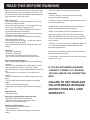
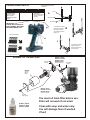
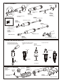
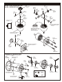
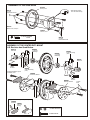
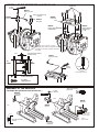
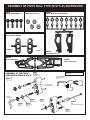
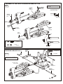
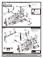
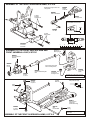
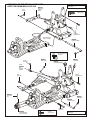
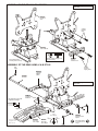
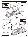
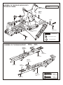
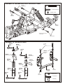
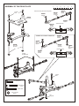
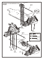
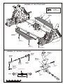
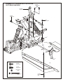
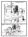
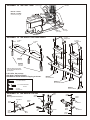
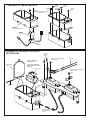
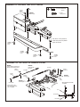
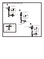
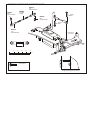
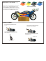
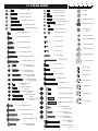
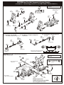
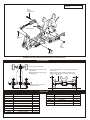
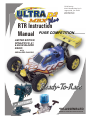
OFNA Racing
22692 Granite Way, Ste. B
Laguna Hills, Ca. 92653
(949) 586-2910
Www.ofna.com
RTR Instruction
Manual PURE COMPETITION...........
LIMITED EDITION
OFNA/PICCO .21
& BLUE BLAZER
RADIO
WITH
SERIALIZED CHASSIS
PRE-ASSEMBLED
ASSEMBLED CHASSIS WITH RADIO AND ENGINE
REQUIRED FOR OPERATION
THINGS NEEDED
You will need to buy a few items to start the engine and run the car.
• Use 20% nitro CAR fuel. Do not use airplane fuels, they will over
heat engine.
• Buy long glow plugs, like OFNA/PICCO P-7 (#51007). Use plugs
without idle bar. Do NOT buy hot plugs, like the MC-59.
In your box you will find..
• #10218 - Red “C” size glow heater
P-7S
Glow Fuel
20%
51007
#10211 Battery Pack 1000 NiMh
5cell, flat............... $29.95
#10214 Battery Charger, Overnite
$7.95
You need to get batteries for the radio transmitter and the car receiver
packs.
• Radio TX needs (8) eight AA batteries
• Car needs (4) four AA batteries.
AA Batteries ( 12 pcs )
Recommendation:
You may want to upgrade the car battery pack to a Ni-Mh 5 cell Flat
type. This will give more run time.
TOOLS NOT INCLUDED IN KIT
Instant Cemment
Cutter
Phillips Type Screw Drivers ( L )
Curved Scissors
Masking Tape
Phillips Type Screw Drivers ( S )
Brush
Cross Wrench
#17109 $3.95
Paints
Needle Nose Pliers
Knife
Glow Plug & 17MM Cross Wrench
#10801 $6.95
READ THIS BEFORE RUNNING
Running a nitro kit is fun and easy, but to make this a safe
and good experience you must observe a few rules. This
kit is extremely fast, easily over 40MPH, and can seriously
injure someone if you are not careful.
Where to run car?
• Any running area you choose must be dry. Do not run
car near any water or wet dirt.
• Do not run on public streets. It is very easy to have the
car run over or damaged by hitting the curb.
• Do not operate car in tight confined places. The car is
very fast and will easily hit something.
• Do not run near people or animals. The car is very fast
and will too easily hit someone.
• Due noise, you will want to consider the surrounding
area when operating the car.
• Do not operate the car at night. You will not be able to
drive it without hitting something.
• Do not operate the car indoors. Engine exhaust is not
healthy.
Glow Fuel
• Glow fuel is poisonous!
• Glow fuel is flammable!
• Do not leave in fuel bottle with lid off at any time.
• Don use any fuel other than glow fuel in this engine.
First Time Starting the Engine
Caution! When starting engine make sure the following is
observed.
• Oil the air filter FOAM Element! OFNA #10015.. $9.95
• Set engine Master needle to 4 turns (rich setting)
• Do not do this alone, get an experienced friend to help at
first.
• Fill fuel tank, try not to spill fuel. Do not spill fuel on
receiver
• Hold car off the ground, so it will not runaway when first
starts
• Turn on Radio and check the linkage before starting
engine.
• Turn on car receiver battery switch.
• Always have an air filter on the carburetor to keep dirt
out.
Engine Break-in
• See Engine Page.
Emergency Stopping Engine When Running
• Remove air filter and cover carb. intake.
• Squeeze fuel line and hold until engine stops.
• With a rag, cover exhaust outlet.
Storing Car After Running
• Remove fuel from tank and fuel lines
• Turn off radio in car
• Put a few drops of after run in engine to keep it from
rusting.
• Clear oil and dirt from chassis with a degreaser.
Precautions
• This kit is not a toy. Always run car with a second
person as a spotter and pitman.
• Hot Parts - The pipe, manifold, engine and head are very
hot and will cause burns.
• Rotating Parts - Keep hands away from the drive train,
wheels, and engine when engine is running.
• Radio - Check batteries life before running the car. If
radio does not have full control of the car with steering
and/or throttle/brake do not run until corrected. Failure to
correct this will result in possible injury and damage to the
car or property.
• Glow fuel - Do leave the glow fuel unattended with the lid
off. Fuel contains Methanol and Nitro Methane and is
flammable and poisonous.
Store fuel in cool ventilated location. Refer the glow fuel
label for additional precautions.
• Car Fuel tank - Never store fuel in car tank, it will ruin the
engine if left in tank.
IF YOU DO NOT BREAK-IN ENGINE
CORRECTLY, MAINLY AT LOW RPM,
YOU WILL BREAK THE CONNECTING
ROD!
FAILURE TO NOT READ AND
FOLLOW BREAK-IN ENGINE
INSTRUCTIONS WILL VOID
WARRANTY!
* Align throttle servo same
as shown.
CHECKING ENGINE THROTTLE
A
C
B
1. Insert AA batteries into
transmitter (8 Pcs).
2.Turn on transmitter.
3.Turn on receiver.
4.Center throttle trims as
shown .
1. Pull Full Throttle.
1. Push trigger to full
brake position.
2. Adjust alum. Stopper to
increase or decrease
the brake.
Brake ©
A
Idle Position (A)
Full Throttle (B)
IMPORTANT
CHECK RADIO THROTTLE
AND STEERING SWITCHES
BEFORE RUNNING CAR
• Full throttle arm position.
Spring rod pulls throttle
barrel open and brake
rods release pressure on
brake cams.
B
* Insert into transmitter.
C
B
C
A
• Full brake arm position.
Spring compresses
forward and brake rods
pull brake levers.
ASSEMBLY OF THE AIR FILTER
Nylon Strap
( Small )
#10021 - Black
#10027 - Yellow
#10028 - Pink
#10029 - Blue
Air Filter Connector
Nylon Strap
( Small )
#10016
Air Filter
Sponge
Refills
#10017 - Blue
#10018 - Yellow
#10019 - Rose
Foam Air filters Unit
3 x 10mm
Tapping Screw
You must oil foam filter before use.
Filter will not work if not oiled.
#10015, Foam
Filter oil, Very
Sticky....$9.95
Clean with soap and water only.
You will damage foam if washed
if fuel!
PLASTIC PARTS USED
#30010
Main Gear Box
#30751 - Frt & Rr Cases
#30761 - Center Case
(K type cases)
#30769 Bevel Gear
Set, for K type case.
#36902 Lower arm, Rear (K), Straight type
#36060 C Hubs (K)
#36011 lower arm, Front (K), Straight type
#36081 Rear Uprights
8mm (K & M)
#36690 Rear Upper Arm Ball
Ends 7mm
#36020 Upper
¤
W
«\Â
Arm,uÁe
frt (K)
#30200 Center Diff Mounts
#36051 Knuckles, 8mm
(K)
#36710 Rear Support
bracket
#36700 Steering Ball Ends, 7mm
#30270 Rear Wing Support set
#36740 Servo Saver set
#30800 Linkage, throttle kit
Plastic Collar
Plastic Bearing
#36780 Battery & Receiver Box
Plastic Post
Servo Mount
Radio Tray Post
#36820 Chassis Stone Guards
SHOCK ASSEMBLY
2.6mm Nut
* Fit into groove.
2.6 x 5mm
Washer
Oil Seal
2mm
Washer
1mm
Washer
Piston
Shock Cylinder
#32203
*Push Onto Shock
Cylinder
Option:
Shock Shaft
#32039
Dust Pusher
(Yellow Rubber)
#32237
O-Ring, rebuild
7mm
E-Ring
O-ring Pistons
#32235
* Assembly 4 pieces of the
shock Shaft .
Teflon Piston Set
#32291
* E-Ring must
fit into groove as shown.
Front, Short(w-gt) Shaft, 3.2mm
#32051
* Short shaft for front.
6mm Ball End,
Plastic parts bag
#32236
E-Ring
Rear, Long Shaft, 3.2mm
( Make 2 for front.)
Hard Coated Shocks:
Front Super Shock, 3.5mm
# 32290
Rear Super Shock, 3.5mm
# 32230
* Long shaft for rear.
( Make 2 for rear. )
#32051
6mm Ball End,
Plastic parts bag
* Be careful not to damage shock shaft.
FILLING THE SHOCKS WITH OIL
1. Pull down piston and pour oil into
shock cylinder. Remove air bubbles
by slowly moving piston up and down.
2. Pull down piston, attach pressure top
and shock oil overflow with tissue
paper.
3. Tighten up shock cap.
#32044
Shock Cap, Hard Coated
OIL
*Leave 3mm.
* Screw down cap.
*Move Slowly.
# 32033
Pressure Top
*Pull down.
* Fit into groove.
Optional:
ASSEMBLY OF THE SPRING
Spring Holder
#32051
All Plastic shock
parts bag
*Slide spring collar into Shock.
#32330
Red Spring set
#32340
#37380
6mm
Ball Joint
Yellow Spring Set
¼
®
Â
u
1mm
* Push 6mm ball joint
into ball end.
3mm
#32204
Spring Collar
Spring Spacer Clips Set 5mm
*Spring Tension adjuster.
ASSEMBLY OF NEW “K” STYLE DIFFERENTIAL CASE AND GEARS
#31324 - FRONT OR REAR DIFF UNIT
#31325 - CENTER DIFF UNIT
30769
Diff. Bevel Gear
( Large )
30779
4 x 10mm
Washer
30771
Diff. Shaft
30779
2 x 12.8mm
Pin
30769
Diff.
Bevel Gear
( Small )
30769
Diff.
Bevel Gear
( Small )
30773
4mm
Cross Pin
30779
4 x 10mm
Washer
30779
P5 O-Ring
( Orange )
30773
4mm
Cross Pin
30779
0.5 x 26mm
O-Ring
* Position the O-ring
as shown.
30769
Diff.
Bevel Gear
( Small )
30779
4 x 10mm
Washer
NB. It is very important to remove
the 30779 shim if the mesh
is too tight.
Grease
* Apply diff. Gear grease to the
differential, during assembly.
* Fill the diff. Case to
approx 70% with grease.
30751 Diff. Case ( Front/Rear )
30761 Diff. Case (Center )
30779
2 x 12.8mm
Pin
3x10mm
Tapping Screw
30771
Diff. Shaft
30779
P5 O-Ring
( Orange )
30751 Diff. Case ( Front/Rear )
30761 Diff. Case (Center )
30769
Diff.
Bevel Gear
( Large )
3x10mm
Tapping Screw
ASSEMBLY OF THE BEVEL GEAR
( Builds two differentials for front and rear. )
30120
Bevel Gear
(Large/Metal)
S
Cecrew
me
nt
31010
Optional - Bevel Gear
(Harden Steel)
30121
3mm
Tube
* Push 3mm tubes into
holes of the diff. Case.
* Notice the straight holes
are for front and rear.
w
re ent
Sc e m
C
30121
3 x 5mm
Screw
36730
Cap Joint
30121
3mm
Tube
90026
5 x 5mm
Set Screw
90026
5 x 5mm
Set Screw
30620
7 x 19mm
Bal lbearings
5 x 5mm
Set Screw
30121
3 x 5mm
Screw
(Small Head)
3 x 5mm
Screw
30620
7 x 19mm
Ball bearings
39730
Cap Joint
ASSEMBLY OF THE SPUR GEAR
#31040
Steel Spur Gear
#30111
* Notice the tapered holes
are for the center diff. Only.
3 x 10mm
Flat Head Screw & Nut
M3
Nylon Nut
#31323
Diff Unit, Center, Complete
#30760
Diff Case, Center
3 x 10 mm Flat Head
Screw
#30111
3 x 10mm
Flat Head Screw & Nut
ASSEMBLY OF THE CENTER DIFF. MOUNT
U.S. Revision has Quad Brakes
#30620
#30170
7 x 19x 5mm
Ballbearings
Brake Joint
#30201
#30620
Center Diff. Housing
( Rear )
7 x 19x 5mm
Ballbearings
#30170
Brake Joint
Screw
Cement
5 x 5mm
Set Screw
#30201
Installing Quad Brakes, requires
an 3x20mm screws
Center Diff. Housing
( Rear )
#36650
Brake Disk, Stainless
Screw
Cement
#36650
5 x 5mm
Set Screw
Brake Disk, Stainless
* Apply instant cement to glue brake pad and packing.
#36660
Brake Pad
#36661
Brake Pad
Packing
5 x 5mm Set Screw
3 x 20mm Screw
3 x 20mm
Screw
3 x 10mm
Tapping Screw
ASSEMBLY OF THE CENTER DIFF. AND BRAKE CAM
Screw
Cement
3 x 3mm
Set Screw
#30171
Brake Lever, Lower
* Notice: The direction of the
brake cam.
#30213
#30652
Brake Cam
Center Plate
#30213
Brake Cam
#30212
#30212
Bearing, Brake Cam
4X8mm Flanged
Bearing, Brake Cam
4X8mm Flanged
Parts drawn are not shown correctly.
A few parts have been changed and may
look different, but part numbers reflect the
new parts.
* Leave 3mm distance between
brake cam and nut.
3mm
#30171
Brake Lever, Upper
TO
FRONT
TO
REAR
ew t
Scermen
C
0.5mm
3 x 3mm
Set Screw
Adjust brake pad spacing.
3 x 3mm Set Screw
3 x 10mm
Tapping Screw
ASSEMBLY OF THE GEAR BOX
* Place set screw on flat
of gear shaft.
( Assemble two gear boxes for front and rear. )
#30630
6 x 13 x 5mm
Ball Bearing
5 x 5mm
Set Screw
Screw
Cement
Step 2
#30130
Bevel Gear
Step 1
#36730
Cap Joint
GEAR
GREASE
You can use a shim
here if gear mesh
needs to be tighter.
* Insert two ball bearings
as shown.
#30779
Misc. Hardware
#30630
6 x 13 x 5mm
Ball Bearing
#30010
Main Gear Box
* Make two gear boxes for front and
rear.
4 x 20mm
Flat Head
Tapping Screw
GEAR
GREASE
#30010
Main Gear Box
3 x 20mm Flat Head
Tapping Screw
ASSEMBLY OF THE FRONT SHOCK TOWER
#36670
Alum. Blue Front
Upper Arm Holder
#36620
Front Shock Tower
4 x 10mm
Tapping Screw
#30340
Anti-roll Bar Kit
4 x 10mm
Tapping Screw
* Insert front stabilizer before
assembly shock tower.
ASSEMBLY OF PIVOT BALL TYPE (M STYLE) SUSPENSION
#36903
13.8mm Steering Ball x 4
#36904
14mm Alum. Nut x 4
#36905
Plastic Washer & Arm Adjusters
#36901
Ball Type Knuckle Arm
( Right )
( Left )
#36900
Front Upper Arm
#36890
Front Lower Arm
#36902
Rear Lower Arm
ASSEMBLY OF THE FRONT
SUSPENSION ARMS, M STYLE
#36901
Assembly of the right and left hand side
are the same.
Ball Type
Knuckle Arm
( Right and Left )
* Adjusr alum. Nut to
keep steering ball
smoot.
Step 1
R
* Note the "R" mark
are for rightside.
* Use 5mm
hex wrench.
#36903
13.8mm
Steering Ball
#36904
14mm
Alum. Nut
#36905
#36053
8x16mm
Ball Bearing
#36052
R
CVA,
Constant Velocity Axle, 8mm
Steering Ball
Washer
#36053
8x16mm
Ball Bearing
ASSEMBLY OF THE FRONT SUSPENSION ARMS, M STYLE
Step 2
#36890
Front
Lower Arm
Assembly of the right and left hand side
are the same.
#36870
4x10mm
Set Screw
* A 4 x 10mm set screw is used
to adjust the ride height.
#36055
2.5 x 17mm
Pin
R
* Approx 3mm.
5 x 5mm
Set Screw
#36054
Wheel Hub
( Alum. )
* Use 2.5mm
Hex Wrench.
#36900
Front
Upper Arm
R
5x5mm
Set Screw
3mm
* Do not over tighten
5x5mm set screw.
4 x 10 mm
Set Screw
5 x 5mm
Set Screw
ASSEMBLY OF THE FRONT
3mm
SUSPENSION ARMS, M STYLE E-Ring
3mm
#36720
4 x 10mm
Tapping Screw
Lower Arm
Stiffener
(Alum.)
3 mm E-Ring
Step 3
Assembly of the right and left hand side
are the same.
* Insert drive shaft
before assembly.
1
4 x 10mm
Tapping Screw
0
#36630
Lower Arm Shaft
R
3mm
E-Ring
ASSEMBLY OF THE FRONT SUSPENSION ARMS, M STYLE
Step 4
* Cut the sharded area
as shown.
Assembly of the right and left hand side
are the same.
3mm
E-Ring
3 x 3mm
Set Screw
#30102
Front Body
Post
3 x 3mm Set Screw
3 mm E-Ring
3 x 8mm
Tapping Screw
3x8mm
Tapping Screw
#30340
6mm
Stabilizer
Ball End
#36640
Upper arm Shaft
1
0
R
3mm
E-Ring
Step 5
Assembly of the right and left hand side
are the same.
#30401
6mm
Stabilizer
Ball End
#36905
Arm Adjusters
#30402
1mm
3 X 30mm
Tie Rod
#30401
3mm
* Insert caster angle adjuster onto the
upper arm shaft.
* Change the position of the adjuster
to will change the caster angle.
2mm
6mm
Stabilizer
Ball End
* Insert stabilizer rod
through upper arm.
#30411
6mm
Ball Joint
3 x 15mm
Screw
1
R
0
18mm
0
10
20
30
40
50
3 x 15mm Screw
mm
ASSEMBLY OF THE REAR SUSPENSION ARMS, M STYLE
* Follow the main instruction manual to assembly the rear lower arm M parts instead of K parts.
ASSEMBLY OF THE FRONT SUSPENSION ARMS, K STYLE
#36860
* Builds two front upper arms for left
and right-side. .
5x40mm
Turnbuckle
#36690
Plastic, Arm Ball End
3 x 20mm
Flat Head
Tapping Screw
#36020
Front, Upper Arms
* If too tight, cut or sand to fit
the shaded area as shown.
0.5MM
#36850
7mm Ball
4 x 15mm
Tapping Screw
* Anticlockwise mark.
1
0
13mm
#30160
0
Front Lower
Arm Holder
10
20
30
40
50
mm
#36120
ASSEMBLY OF THE FRONT KNUCKLE ARM AND
FRONT UNIVERSAL JOINT, K STYLE
Knuckle arm
Bushing & screw
#36051
Front, Knuckle Arms
(R/L) 8mm
#36053
R
Bearing
8 x 16 x 5
* Insert knuckle arm bushing
before assembly knuckle.
#36060
#36052
#36053
CVA, Constant Velocity Axle
8mm
Bearing
8 x 16 x 5
Front C Hub
(Right)
#36120
Knuckle arm
Bushing & screw
Assembly of the right and left hand side
are the same.
#36870
4 X 10mm
Set Screw
4 x 10mm
Cap Screw
* A 4 x 10mm set screw is used
to adjust the ride height.
2.5mm
E-Ring
* Approx 3mm.
R
#36011
Front Lower Arm,
straight type
(not shown correctly)
#36870
4 x 10mm
Cap Screw
#36170
3mm
Rear Arm Shaft
2.5mm
E-Ring
Assembly of the right and left hand side
are the same.
ASSEMBLY OF THE FRONT SUSPENSION ARMS, K STYLE
ASSEMBLY OF THE FRONT LOWER ARMS
ONTO THE GEAR BOX, K STLYLE #36720
Assembly of the right and left hand side
are the same.
Lower Arms
Stiffener
(Alum.)
3mm
E-Ring
4 x 10mm
Tapping Screw
4 x 10mm
Tapping Screw
1
0
* Insert drive shaft
before assembly.
#36630
Lower Arms Shaft
R
* Cut the sharded area
as shown.
#90021
3 x 3mm
Set Screw
#90021
3mm E-Ring
3mm E-Ring
#30102
Front Body Post
A-34B
#30340
6mm
Stabilizer
Ball End
3x8mm
Tapping Screw
3mm
Nylon Nut
1
#36055
0
R
2.5 x 17mm
Pin
#90021
3mm E-Ring
#36640
Upper arm Shaft
3 x 25mm
Cap Screw
#36054
17mm Wheel Hub
( Alum. ) 8mm Axle
3 x 8mm
Tapping Screw
Assembly of the right and left hand side
are the same.
ASSEMBLY OF THE
STABILIZER ROD
#30402
#30401
Assembly of the right and left hand side
are the same.
6mm Plastic
Stabilizer
Ball End
3 X 30mm
Tie Rod
#30401
3 x 25mm
Cap Screw
#36610
6mm Plastic
Stabilizer
Ball End
Spacer, Shock Support
3 x 15mm
Screw
* Insert into arms.
#30411
6mm
Ball Joint
1
0
R
14mm
3 x 25mm
Cap Screw
10
20
30
40
50
3 x 15mm Screw
mm
Assembly of the right and left hand side
are the same.
ASSEMBLY OF THE SHOCKS ONTO
THE SHOCK TOWER
#30411
6mm
Ball Joint
3 x 8mm
Washer
* Cut the shaded area as shown
w t
re en
Sc em
C
1
0
R
0
3mm
Nylon Locknut
* Insert shocks ball end
into arms.
3 x 15mm Screw
M3 Nylon Locknut
3 x 15mm
Screw
3 X 8mm Washer
ASSEMBLY OF THE REAR SHOCK TOWER
Assembly of the right and left hand side
are the same.
#36810
Rear Shock
Tower
3 x 20mm
Flat Head
Screw
#30340
Anti-roll Bar Kitr
* Don't over tighten tapping screw,
will cause bending.
* Insert stabilizer before
assembly of the shock stay.
#36090
Rear Arm
Holder & Toe-in
ASSEMBLY OF THE REAR ARMS, K & M STYLE
4x16mm
Flat Head
Tapping Screw
3mm
E-Ring
#36720
#36630
Lower Arm
Stiffener
(Alum.)
Arm Shaft
Assembly of the right and left hand side
are the same.
#36870
* A 4 x 10mm set screw is used
to adjust the ride height.
4 X 10mm
Set Screw
* Approx 3mm.
3mm
E-Ring
Fig.1
Toe-in Settings
1
Degree
Arm shown has been
changed and not
drawn correctly.
#36902
Rear Lower
Arms, K Style
#36090
Rear Wheel Toe-in
Adjuster
1.5
Degree
#36902
Rear Lower
Arms, M Style
3mm
E-Ring
* Set triangle marks in
the direction shown
in Fig.1.
ASSEMBLY OF THE REAR HUB, K & M STYLE
* Builds two upper Rods for left
and right-side.
#36880
5x60mm
Turnbuckle
#36690
#36053
Arm Ball End
8 x 16 x 5
Ball Bearings
#36690
#36082
Arm Ball End
Rear Wheel
8mm Axle Shaft
#36053
8 x 16 x 5
Ball Bearings
#36054
Rear Hub
K or M Style
#36850
7mm Ball
#36055
2.5 x 17mm
Pin
* Anticlockwise mark.
#36054
Wheel Hub
( Alum. )
40mm
0
10
20
Assembly of the right and left hand side
are the same.
40
50
mm
ASSEMBLY OF THE REAR HUBS ONTO
THE REAR ARMS, K & M STYLE
2.5mm
E-Ring
30
Assembly of the right and left hand side
are the same.
* Insert rear drive shaft
befor assembly.
#36110
Rear Drive
Shaft
5x5mm
Set Screw
* Do not overtightened
set screw.
2.5mm
E-Ring
#36170
3mm
Rear Arm Shaft
3 x 25mm
Cap Screw
ASSEMBLY OF THE REAR UPPER ARM ROD
Assembly of the right and left hand side
are the same.
G-01
Shock Support
3 x 25mm
Cap Screw
M3
Nylon Locknut
3 X 25mm Cap Screw
M3 Nylon Locknut
* Insert into rear hub.
3mm
Nylon Locknut
3 x 15mm
Screw
3 x 25mm
Cap Screw
ASSEMBLY OF THE STABILIZER ROD
3 x 15mm Screw
#30401
6mm
Stabilizer
Ball End
#30402
3 X 30mm
Tie Rod
3 x 3mm
Set Screw
#30401
#30340
6mm
Stabilizer
Ball End
6mm
Stabilizer
Ball End
#30411
3 x 15mm
Screw
6mm
Ball Joint
15mm
0
10
20
30
40
50
mm
Assembly of the right and left hand side
are the same.
ASSEMBLY OF THE REAR SHOCKS ONTO
THE SHOCK TOWER
Assembly of the right and left hand side
are the same.
#36610
Spacer, Shock Support
#30411
6mm
Ball Joint
3 x 8mm
Washer
rew t
Scemen
C
3mm
Nylon Locknut
* Insert shock ball end
into arm.
3 x 15mm Screw
3mm Nylon Locknut
3 X 8mm Washer
3 x 15mm
Screw
ASSEMBLY OF THE WING SUPPORT
#30370
Wing Support
#30371
Wing Mount
#30270
Wing Support
( Right )
3 x25mm
Tapping Screw
3 x 20mm
Tapping screw
#30370
Wing Support
Plastic Post
3 x25mm
Tapping Screw
#30270
Wing Support
(Left)
3 x 20mm
Tapping screw
3 x 25mm
Tapping Screw
3 x 20mm
Tapping Screw
ASSEMBLY OF THE WING STAY ONTO THE SHOCK TOWER
4 x 15mm
Tapping Screw
3 X 25mm Cap Screw
4 x 15mm Tapping Screw
M3 Nylon Locknut
3 x 25mm
Cap Screw
Wing Stay
Assembly
* Insert 3mm nylon locknut
into win stay.
3mm
Nylon Locknut
ASSEMBLY OF THE SERVO SAVER
#36743
6mm
E-Ring
3 x 15mm
Screw
#36740
Servo Saver Kit
#36743
6mm
E-Ring
#36742
Servo Saver
Bushing
#36740
Servo Saver Kit
#36740
Servo Saver Kit
#36741
#36740
Servo Saver
Spring
Servo Saver Kit
#36740
Servo Saver Kit
Plastic Tube
#36744
Saver Saver
Post
#36744
Saver Saver
Post
#36743
#36743
6mm
E-Ring
6mm
E-Ring
#36750
3mm
Nylon Nut
Servo Saver
Connector
3mm
Nylon Nut
M3 Nylon Locknut
3 x 15mm Screw
6 mm E-Ring
ASSEMBLY OF THE FRONT PLATE
0
10
20
30
40
50
mm
#36700
* Made two steering rods for left and right-side.
3 X 10mm
Screw
Steering
Ball End
#36790
4 x 46mm
Turnbuckle
#36850
7mm Ball
#36760
Front Plate
#36850
7mm Ball
#36700
* Anticlockwise mark.
Steering
Ball End
31mm
* ASSEMBLY OF THE FRONT TORQUE ROD
#36680
Steering
Ball End
#36680
7mm
Ball & Socket
Support
#30380
#36790
4 x 46mm
Turnbuckle
Servo Saver
Axle Posts
* Anticlockwise mark.
#36680
3 x 20mm
Flat Head Screw
Steering
Ball End
33mm
3 x 25mm
Screw
3 x 15mm Screw
3 x 20mm Flat Head
Screw
3 x 25mm Screw
3mm Flange Nut
( Steel )
3mm
Flange Nut
rew nt
Sceme
C
#36680
7mm
Ball & Socket
Support
ASSEMBLY OF THE FRONT PLATE
ONTO THE FRONT GEAR BOX
3 x 10mm
Tapping Screw
3 x 15mm
Flat Head
Screw
3 x 15mm
Flat Head
Screw
Knuckle arm of the
left-side.
Scre
w
Cem
ent
Scre
w
Cem
ent
1
0
R
3 x 10mm
Tapping Screw
3 x 15mm Flat Head
Screw
ASSEMBLY OF THE FRONT GEAR BOX ONTO CHASSIS
1
0
R
#36840
Chassis, Hard Coated
* Insert the front bumper
before assembly.
#30240
Front Bumper
4 x 16mm
Flat Head
Tapping Screw
3 x 10 mm
Flat Head
Screw
* A 3 x 10mm
flat head screw are for servo post.
3 x 10mm
Flat Head
Screw
4 x 16mm
Flat Head
Tapping Screw
4 x 16mm
Flat Head
Tapping Screw
Center Diff. Assembly
ASSEMBLY OF THE CENTER DIFF. ONTO
CHASSIS
#36110
Center Drive
Shaft
* Insert drive shaft into
cap joint.
1
0
R
4 x 16mm
Flat Head
Tapping Screw
3 x 25mm
Flat Head
Tapping Screw
#36110
Center Drive
Shaft
* Insert drive shaft into cap joint.
4 x 16mm
Flat Head
Tapping Screw
3 x 25mm Flat Head
Tapping Screw
3 x 25mm Flat Head
Screw
M3
Flange Nut
4 x 16mm
Flat Head
Tapping Screw
3 x 25mm
Flat Head
Screw
1
R
4 x 16mm
Flat Head
Tapping Screw
0
ASSEMBLY OF THE STONE GUARD
3 x 10mm
Tapping Screw
3 x 10mm
Tapping Screw
#36820
Stone Guard
#36820
Stone Guard
1
3 x 10mm
Tapping Screw
0
R
3 x 10mm
Tapping Screw
3 x 10mm
Tapping Screw
ASSEMBLY OF THE REAR TORQUE ROD
#36710
Rear Stiffener &
Body Mount
#36700
Steering
Ball End
#36700
Steering
Ball End
#36710
Rear Stiffener &
Body Mount
#36790
4 x 46mm
Turnbuckle
#36850
7mm Ball
3 x 20mm
Screw
#36680
7mm
Ball & Socket
Support
* Anticlockwise mark.
(REAR)
3 x 20mm
Screw
35mm
0
10
20
30
40
50
mm
ASSEMBLY OF THE REAR BODY SUPPORTER
ONTO REAR GEAR BOX
3 x 10mm
Tapping Screw
Rear Body
Supporter Assembly
4 x 10mm
Tapping Screw
M3
Flange Nut
4 x 10mm
Tapping Screw
3 x 10mm
Tapping Screw
M3 Flange Nut
( Steel )
3 x 25mm Flat Head
Screw
3 x 25mm
Flat Head
Screw
ASSEMBLY OF THE CLUTCH INTO ENGINE
Notes:
Non-Pull Start Engines...
• Alum. Washer behind the flywheel is not needed when using Force engines or similar types. O.S. Engines will
require washer spacer.
3 x 5mm Screw
• To check!..place the brass corn #10330 (big hole) against the engine bearing, then flywheel. You should be
covering one or two thread of the engine shaft. If this is the case, you do not need an additional washer behind the
flywheel.
3 X 8mm
Washer
You must cut the engine shaft if too long. Count 6 threads in front of the flywheel and mark. This is all you need to
tighten the clutch nut and mount the flywheel.
3 x 20mm
Cap Screw
3 x 20mm
Hex Screw
3 x 20mm
Hex Screw
Force Pull Start Engine...
• Force Pull Start Engines required NO additional spacer and no shaft cutting. The Force engines comes with an
alum. cast driver washer, you use this part as the spacer, not the alum. washer shown for O.S. installs
3mm Nylon
Locknut
But, you must find the #10329 brass corn (sml hole) for Flywheel. This special corn fits the smaller thread
diameter of the engine shaft. It will center the flywheel when tightening the clutch nut.
#10010
#10398 - 12T
#10399 - 13T
#10400 - 14T (stock)
#10401 - 15T
#10402 - 16T
#10403 - 17T
#10404 - 18T
Clutch Bells
#10100
Clutch Spring
Clutch Shoes
Black Type
#10330
Brass, Corn (big hole)
#10329
Brass, Corn (sml hole)
3mm
Nylon Lock
Nut
#34110
5x10x4mm
Ball Bearing
#34110
5x10x4mm
Ball Bearing
SEE NOTES ABOVE
#10091
#10040 (stock)
Clutch Nut
screw type
3 x 8mm
Washer
Misc. Hardware
3 x 5mm
Screw
3 Pin
Flywheel, Taper
#10041
* Shoes are
trailing.
#10099
3 Pin
Flywheel, Hole
3mm
Nylon Lock
Nut
#30480
Engine Mount
#10098
SG Nut & Shim KiT
* Fit the flywheel using a cross
wrench or deep socket.
If engine turns when tightening,
hold piston with large thick tie-wraps
and hard wood in exhaust port.
Do not use metal, it will
damage engine.
* Place the clutch shoes
with the clutch springs
over the 3 pins of the
flywheel.
Using a screw driver as a lever,
bend the small end of the
clutch spring behind the
clutch nut and press
down to snap shoe in
place.
ASSEMBLY OF THE AIR FILTER
You must oil foam filter before use.
Filter will not work if not oiled.
Nylon Strap
( Small )
Clean with soap and water only.
You will damage foam if washed
if fuel!
#10016
Air Filter
Sponge
Refills
#10017 - Blue
#10018 - Yellow
#10019 - Rose
Foam Air filters
3 x 10mm
Tapping Screw
Engines with ground shafts and few threads
are called SG Shaft. A special clutch nut is needed.
The stock flywheel (#10040) is fine.
#10021 - Black
#10027 - Yellow
#10028 - Pink
#10029 - Blue
Air Filter Connector
Nylon Strap
( Small )
3 x 15mm
Screw
Pressure Nipple
INSTALLATION OF THE FUEL TANK
AND ENGINE ONTO CHASSIS
#30280
Fuel Nipple
Fuel Tank
3 x 15mm
Screw
Note Book Paper
3 X 20mm
Cap Screw
Plastic Post
Plastic Post
*Use note book paper to set
gear backlash between spur gear
and clutch bell gear.
If the space is not correct the spur gear
will be damaged.
* Take the plastic post
from the receiver box
plastic parts.
Spur Gear
Clutch Bell
5x12mm
Washer
( 4 pcs )
* Loose or tighten 3x20mm cap screw
and 5x10mm hex screw to align
spur gear and clutch bell same
as shown.
3 x 10mm
Tapping Screw
3 x 10mm
Tapping Screw
5x10mm
Hex Screw
( 4 pcs )
#10111
Motor Mount Screw set
#10069
ASSEMBLY OF THE MANIFOLD AND
MUFFLER
Manifold Adapter
( Red Silicone )
#31991
Manifold, Polished
#10120
Manifold
Spring
4mm
Nylon
Locknut
*Tighten the strap
and cut off the excess.
#30491
Muffler Mount
Wire
You must bend wire as
shown,
4x1omm
Flat Head
Screw
Nylon Strap
( Large )
#10079
Alum. CNC
Pressure Nipple
#10184
Blue, Silicone Tube
* Drill a hole (Size 3.5mm)
in the place and align as shown.
Use a two part high temp. epoxy glue to
fully seal the nipple base.
5x5mm
Set Screw
#31992
Dual Chamber, Polished
ASSEMBLY OF THE FUEL TUBE
* Connect to fuel tank
pessure nipple.
* Connect to
carbulater.
#10178 - Yellow
#10179 - Lt. Blue
Silicone Fuel Tubing, 3ft.
* Connect to
press nipple.
* Connect to
fuel nipple.
ASSEMBLY OF THE RADIO TRAY AND SERVO
3 x 10mm
Screw
3 x 10mm
Tapping Screw
3 x 10mm
Tapping Screw
3 x 10mm
Screw
Throttle Servo
#36770
Steering Servo
Radio Tray
#30520
Radio Tray
Post, Alum.
* Take the radio tray post and
servo post from receiver box
plastic parts.
In U.S. Kits, the post are
CNC Alum. Instead of Plastic
Use Machine Screw instead of Tapping as shown.
3 x 10mm Screw
#10273
Servo Post Mounts
#10273
Servo Post Mounts
3 x 10 mm Flat Head
Screw
#10273
3 x 10mm
Tapping Screw
Servo Post Mounts
ASSEMBLY OF THE BRAKE SYSTEM
#30800
2x8mm
Screw
3x12mm
Screw
Brake System Plastic Parts Set
2x4mm
Screw
2x6mm
Washer
Slider
Servo Mount
3X3mm
Set Screw
2x25mm
Screw
2mm
Tie-Rod End
Scre
w
Cem
ent
A-80B
2mm
Adjust Nut
Adjust
Mount
3mm
Nut
2mm Nut
2x6mm
Washer
2x4mm
Screw
2mm
Tie-Rod End
ASSEMBLY OF THE RECIVER BOX
2x8mm
Screw
2x8mm
Screw
2x8mm
Screw
2x8mm
Screw
2x8mm
Screw
* Use the screw provided
with your radio.
#36780
Receiver & Battery Box
#10280
Switch Cover
Switch
(with radio)
ASSEMBLY OF THE RADIO TRAY ONTO
RECEIVER BOX
* Put the receiver and
battery into box.
Receiver Box
Cover
3x10mm
Tapping
Screw
* Use the horn & screw provided
with your radio.
2mm Rod
* Keep radio and battery
from moving in box. Pack
with foam.
Receiver & Battery
* Use the horn & screw provided
with your radio.
3x25mm
Screw
Antenna
Wire
* Insert Into Receiver
Box and connect to
receiver.
ASSEMBLY OF THE RADIO TRAY ONTO CHASSIS
3 x 10 mm Flat Head
Screw
3x10mm
Tapping
Screw
#30560
3 x 10mm
Tapping Screw
Antenna Tube
Use Alum. CNC posts for
radio tray and not plastic
type as shown!
3X10MM
Flat Head
Screw
3X10MM
Flat Head
Screw
3X10MM
Flat Head
Screw
3X10MM
Flat Head
Screw
ASSEMBLY OF THE THROTTLE LINKAGE SYSTEM
#30800
#30530
Throttle and Brake Linkage Parts
(Plastic and all Hardware shown)
3X3mm
Set Screw
Plastic Throttle
Ball Joint
* Snap On.
3X3mm
Set Screw
2mm Rod
Throttle
Spring
#10300
3X3mm
Set Screw
Alum.Stopper
Fuel
Tube
( 6mm )
#10300
Alum.Stopper
* Align throttle servo same
as shown.
Plastic Collar
* Take the plastic collar
from brake system plastic
parts. P/n #30800
Brake
Idle Position
Full Throttle
ALIGN THROTTLE SERVO AND BRAKE SAME AS SHOWN
( Neutral Position )
Engine at idle
( Braking Position )
Brake is not on
Brake is on
Brake Adjust Nut
( Full Throttle Position )
Less Brake
More Brake
Loose
Engine at full throttle
Tighten
* Tighten or loose the adjuster nut
will change the brake.
Brake is not on
ASSEMBLY OF THE FRONT STEERING ROD
#30410
6mm
Ball & Socket End
#30402
#30410
3 X 30mm
Tie Rod
6mm
Ball & Socket End
3x12mm
Screw
#30410
6mm
Ball & Socket End
3x12mm
Screw
#30410
6mm
Ball & Socket End
* To the steering
servo saver.
20mm
0
10
20
30
40
50
mm
3 x 12mm Screw
* Align the steering servo as shown.
ASSEMBLY OF THE TIRES, FOAM INSERTS AND WHEELS
-
Red
White
Lime
Yellow
#86091
Mini XX- Pin Tire
R
#86044
#86045
#86046
#86047
17mm 5-Star Wheels
Front Knuckle Arm
Assembly
#15071
17mm Wheel Nuts
Always use tire foam
donut when building tires.
IN
ST
GL ANT
UE
Foam
T
TAN
INS LUE
G
* Apply instant glue into
the groove of the wheel.
Rear Hub Assembly
#81091 - Med/soft
#81092 - Med.
WE RECOMMEND CA GLUE
FOR RUBBER TIRES.
YOUR KIT COMES WITH PRE-GLUED
TIRES, BUT WHEN TIRES ARE WORN
YOU MUST REPLACE THEM. MAKE TIRE
AND WHEEL SET AS SHOWN
#86044
#86045
#86046
#86047
#86048
#86049
#15071
Foam
STARTING OF THE ENGINE
17mm Wheel Nuts
-
Red
White
Lime
Yellow
Black
Chrome
17mm 5-Star Wheels,
Two (2) Pairs per bag.
* To start the engine, use hand held starter
motor or starter box.
How to start the engine:
1. Turn on transmitter and then receiver.
2. Fill fuel tank with fuel bottle.
3. Connect 1.2V glow plug starter.
4. Start engine with 12V starter or starter box
( Note the direction of the starter.)
5. After the engine be started, remove the
1.2V glow plug starter.
* Follow the engine manufacturer instruction manuals
regarding engine set-up, carburetor and maintenance.
Rubber wheel turns engine
flywheel.
#10250
Starter Box
12V Starter
1.2V
Glow Plug
Starter
* Note the direction of the
starter.
Connect with 12V battery
PAINTING TIPS
For BUGGY
STEP 1
Wash the inside of the body with detergent to
remove any oil and dirt. Dry with lint free towel
or a hair dryer. (Keep your hand clean.)
STEP 2
Tools required are: Curved scissor , hobby knife
and a quality masking tape. These can be purchase at your local hobby supplier.
STEP 3
Use the curved scissors to trim the body to
the guide lines provided on you body shell.
STEP 4
Use masking tape on the inside of the body to
mask out your design and windows prior to
painting. Press down the edges!
STEP 5
Paint the inside of the body!
Use a spray color suitable for polycarbonate.
(Paint the darkest color first.)
STEP 6
Allow the paint to dry for at least an hour!
Remove the masking tape and protection film
from the outside of the body.
STER 7
Apply the decals to the outside of the body.
We suggest use a hobby knife to cut them out.
STEP 8
Use a hobby knife to cut holes for the fuel tank ,
engine and antenna tube .
Make two 7mm holes for the body posts; one at
the front and one at the rear.
STEP 9
Drill two 7mm holes in nylon wing.
Using the measurements provided in the
instruction. Use the clip provided to secure the
wing to the wing mount posts.
STER 10
Mounting the body to the buggy using the
body using body clips provided.
Factory Body Shown
# 36830
U.S. Body, in kit
# 36831
ENGINE BREAK-IN AND TUNNING
(BREAK-IN THE ENGINE BEFORE DRIVING THE CAR!)
• Choose a wide clear outdoor location with low dirt and dust.
• Set the car on box or holder with wheels off the ground.
• Turn on radio and car. Make sure throttle is at idle position.
• Fill fuel tank and set master engine needle.
• Prime fuel line and Heat glow plug before pull starting engine.
• When started, let engine fast idle for two tanks of fuel.
OPTIONAL OFNA CAR STANDS
WOOD BLOCK
TUNING AFTER BREAK-IN
Close master needle by turning clockwise until it stops.
Then open needle by turning counterclockwise 3 turns
(rich setting).
When running car, adjust carb with 1/8 clockwise turns,
slowly leaner, until the top speed good. Check engine
temp, if possible, for no more 250 degrees.
Adjust low end needle for best throttle response. Use only
small turns. From idle, give it full throttle, if throttle is slow
lean out needle until good.
Adjust barrel stop so it will not close, accept for a small gap.
This gap will be the idle setting. You will notice the idle will
increase with a wide gap.
Idle adjuster screw &
Barrel Stop
Lean
Rich
0
1:1 SCREW SHEET
10
20
30
40
50
mm
3 x 5mm Cap Screw
3 x 3mm Set Screw
3 x 10mm Cap Screw
3 x 5mm Set Screw
3 x 8mm Set Screw
M3 Nut
M4 Nut
3 x 12mm Cap Screw
3 x 10mm Set Screw
3 x 15mm Cap Screw
3 x 20mm Cap Screw
3 X 25mm Cap Screw
3 x 5mm Tapping Screw
M3 Nylon Locknut
3 x 15mm Set Screw
M4 Nylon Kocknut
4 x 4mm Set Screw
4 x 10 mm Set Screw
M3 Flange Nut
( Steel )
5 x 5mm Set Screw
2 X 6mm Washer
3 x 8mm Tapping Screw
2 x 4mm Screw
2mm X 7mm Washer
3 x 10mm Tapping Screw
2 x 5mm Screw
3 X 8mm Washer
3 x 12mm Tapping Screw
2 x 6mm Screw
5 X 9mm Washer
3 x 15mm Tapping Screw
2 x 8mm screw
2 x 10mm Screw
5 X 10mm Washer
3 x 20mm Tapping Screw
3 x 25mm Tapping Screw
3 x 10mm Flat Head
Tapping Screw
3 x 15mm Flate Head
Tapping Screw
3 x 20mm Flat Head
Tapping Screw
3 x 25mm Flat Head
Tapping Screw
3 x 5 mm Flat Head
Screw
3 x 10 mm Flat Head
Screw
3 x 15mm Flat Head
Screw
3 x 20mm Flat Head
Screw
3 x 25mm Flat Head
Screw
2 x 25mm Screw
3 x 5mm Screw
2mm E-Ring
3 x 10mm Screw
2.5mm E-Ring
3 x 15mm Screw
3 mm E-Ring
3 x 20mm Screw
4 mm E-Ring
3 x 30mm Screw
5 mm E-Ring
4 x 6mm Flat Head Screw
4 x 10mm Flat Head Screw
6 mm E-Ring
4 x 15mm Flat Head Screw
7 mm E-Ring
4 x 20 mm Flat Head Screw
4 x 10mm Tapping Screw
4 x 10mm Flat Head
Tapping Screw
4 x 15mm Tapping Screw
4 x 16mm Flat Head
Tapping Screw
4 x 20 Tapping Screw
4 x 20mm Flat Head
Tapping Screw
4 x 25mm Tapping Screw
3 x 30mm Screw Pin
( Black )
4 x 15mm Tapping Screw
( Small Head )
5 X 12mm Washer
3 x 30mm Screw Pin
( Silver )
#31296 Rear Pivot Ball Suspension System, Buggies
( Available For: 1/8 Scale Buggy-Ultra GT LX, Ultra MBX & MBX +, Worlds, Worlds ll )
ASSEMBLY OF THE REAR HUB
Assembly of the right and left hand side
are the same.
36082
Rear Wheel
Axle Shaft
* Take the 4mm set screw
from your car kit.
36503
8x16mm
Ball bearings
31304
Rear Hub
36870
4mm
Set Screw
* Make sure the pivot ball
move smooth.
31303
Rear
Lower Arm
31307
11mm
Pivot Ball
31306
12mm
Hex Nut
36503
8x16mm
Ball bearings
5mm
Hex Wrench
31305
Ball Washer
ASSEMBLY OF THE REAR UPPER ROD
( Builds 2 upper rods for the left and right-hand side.)
For: Ultra Worlds, use 30093 and 30092 parts
For: Ultra GT LX and Ultra MBX,
from this kit.
use 30093and 30092 from your car.
30093
9mm Upper
Arm Ball End
36850
7mm Ball
36880
5x60
Turnbuckle
For: Ultra Worlds ll, remain the upper rod
as shown.
36850
7mm Ball
36880
5x60
Turn Buckle
36690
7mm
Plastic Ball End
36690
7mm
Plastic Ball End
36690
7mm Ball
30092
9mm
Ball & socket
* Adjust the upper rods length according
to the holes chose for attachment.
36850
7rm Ball End
0
10
20
30
40
50
mm
ASSEMBLY OF THE SUSPENSION ARMS INTO
REAR GEAR BOX
Assembly of the right and left hand side
are the same.
3mm
E-Ring
Arm Shaft
* Use the parts that come
with your kit.
* Set triangle marks in
the direction shown
in Fig.1.
Rear Drive
Shaft
3mm
E-Ring
* Insert rear drive shaft
before assembly.
#36055
Drive Pin
Rear Wheel
Toe-in Adjuster
* Do not r tighten
5x5mm set screw over tighten.
Plastic Washer
(3 pcs)
5x5mm
Set Screw
#36054
Wheel Drive
Nut, 8mm
3mm
E-Ring
Multiple spacers are
needed to fit Kyosho and OFNA
cars using the same arms.
1
Degree
1.5
Degree
Fig.1
ASSEMBLY OF THE UPPER ROD INTO GEAR BOX
Assembly of the right and left hand side
are the same.
30061
4 x 25mm
Flat Head Screw
* Insert into rear hub.
3mm
Nylon Lock
Nut
4mm
Nylon
Lock Nut
3 x 25mm
Cap Screw
ASSEMBLE THE FRONT AND REAR GEAR BOX ONTO CHASSIS AS USUAL.
SETTING GUIDE
REAR WIDTH SETTING
REAR CAMBER SETTING
Adjust A and B to the same length.
Adjusting B longer will make the rear tires
toe-in (Positive).
The rear camber adjustment can be make by changing the length
of the upper rod.
Adjusting A longer will make the rear tires
toe-out (Negative).
Making the upper rod longer will make the camber positive.
Making the upper rod shorter will make the camber negative.
0
0
-
-
0
+
+
0
Upper Rod
+
-
+
-
A
A
B
B
* Use a 2.5mm hex wrench to adjust
the rear track width.
C
C.L
C'
PARTS LIST
Item No.
Description
Qty
#36082
Rear Wheel Axle Shaft
2 pcs
#31303
Rear Lower Arm
1 set
#31304
Rear Hub (Pivot Ball Type)
#31305
#31306
Item No.
Description
Qty
#31307
Pivot Ball
2 pcs
#36890
Front Lower Arm
1 set
2 pcs
#36690
7mm Ball End
4 pcs
Ball Washer
4 pcs
#36850
7mm Ball
4 pcs
Alum. Hex Nut
4 pcs
#36880
5X60 Turnbuckle
2 pcs
#36054
Wheel Drive Nut
2 pcs
#36503
8x16x5mm Ball bearings
8 pcs
#36055
2.5x17mm Drive Pin
4 pcs
#34010
9mm Upper Arm Ball End
2 pcs
#30092
9mm Ball and Socket
2 pcs