1
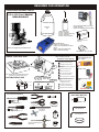
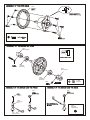
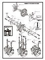
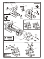
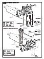
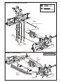
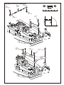
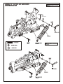
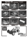
REQUIRED FOR OPERATION
THINGS NEED BESIDES THE KIT
3.5 cc (21 Class) ENGINE
REAR EXHAUST
Glow Plug Heat with Battery & Charger
# 10227....$$19.95
(please note OFNA Glow Heats available)
Glow Fuel
20%
Bottle’s with spout
# 10160 - large 500cc
# 10161 - large 500 ccAuto Stop
# 10162 - small 250cc
# 10164 - CNC spout 500CC
12V Battery for Starter Box
(must have)
Off-Road Starter Box
# 10250 - 1/8 scale Starter Box
# 10253 - 1/8 scale Starter Box w/ Panel
Add-on
# 92571 - Power Panel Glow Heater
# 92572 - Cable for Glow Plug
Note: The engine may not include in kit.
AA Batteries ( 12 pcs ) for radio
Radio must be set at neutral position
before installing in the kit.
SEQUENCE TO SET NEUTRAL
RADIO CONTROL UNIT
More Optional Parts . . .
#10211 NiHm Battery Flat
Pack .. $29.95
Install AA batteries in Radio.
Extend the antenna.(Transmitter)
Install batteries into Car receiver .
After installing the battery, connect the
battery box.
Extend the antenna. (Receiver)
# 10214 NiHm Battery Pack
Charger.. $7.95
Set the trim-leved at center.
Turn on the switch. (Transmitter)
Note: Careful read the instruction manual of your
2 channel radio controller before using.
Turn on the switch. (Receiver)
Make sure the servos are in command.
SUITABLE SERVO SIZE
36m
When the operation stick is in neutral,
servo horns must be in neutral as
will.
*Adjustment can be made by reinstalling the servo horn.
m
m-41m
15mm - 21mm
OFNA/Picoo Glow Plug ..
$4.95
11 Turn off the switch. (Receiver)
29mm - 42mm
12 Turn off the switch. (Transmitter)
13 Retract the antenna. (Transmitter)
TOOLS NOT INCLUDED IN KIT
INCLUDED WITH KIT
Instant Cement
Cutter
Shock Oil
Phillips Type Screw Drivers ( L )
Curved Scissors
Masking Tape
1.5mm Allen Wrench
Brush
Phillips Type Screw Drivers ( S )
Cross Wrench
#17109 $3.95
2.5mm Allen Wrench
Paints
Needle Nose Pliers
Glow Plug & 17MM Cross Wrench
#10801 $6.95
Grease Box
Knife
Grease
READ THIS BEFORE RUNNING
Running a nitro kit is fun and easy, but to make this a safe
and good experience you must observe a few rules. This
kit is extremely fast, easily over 40MPH, and can seriously
injure someone if you are not careful.
Where to run car?
• Any running area you choose must be dry. Do not run
car near any water or wet dirt.
• Do not run on public streets. It is very easy to have the
car run over or damaged by hitting the curb.
• Do not operate car in tight confined places. The car is
very fast and will easily hit something.
• Do not run near people or animals. The car is very fast
and will too easily hit someone.
• Due noise, you will want to consider the surrounding
area when operating the car.
• Do not operate the car at night. You will not be able to
drive it without hitting something.
• Do not operate the car indoors. Engine exhaust is not
healthy.
Glow Fuel
• Glow fuel is poisonous!
• Glow fuel is flammable!
• Do not leave in fuel bottle with lid off at any time.
• Don use any fuel other than glow fuel in this engine.
First Time Starting the Engine
Caution! When starting engine make sure the following is
observed.
• Set engine Master needle to 3 turns (rich setting)
• Do not do this alone, get an experienced friend to help at
first.
• Fill fuel tank, try not to spill fuel. Do not spill fuel on
receiver
• Hold car off the ground, so it will not runaway when first
starts
• Turn on Radio and check the linkage before starting
engine.
• Turn on car receiver battery switch.
• Always have an air filter on the carburetor to keep dirt
out.
Engine Break-in
• See Engine Page.
Emergency Stopping Engine When Running
• Remove air filter and cover carb. intake.
• Squeeze fuel line and hold until engine stops.
• With a rag, cover exhaust outlet.
Storing Car After Running
• Remove fuel from tank and fuel lines
• Turn off radio in car
• Put a few drops of after run in engine to keep it from
rusting.
• Clear oil and dirt from chassis with a degreaser.
Precautions
• This kit is not a toy. Always run car with a second
person as a spotter and pitman.
• Hot Parts - The pipe, manifold, engine and head are very
hot and will cause burns.
• Rotating Parts - Keep hands away from the drive train,
wheels, and engine when engine is running.
• Radio - Check batteries life before running the car. If
radio does not have full control of the car with steering
and/or throttle/brake do not run until corrected. Failure to
correct this will result in possible injury and damage to the
car or property.
• Glow fuel - Do leave the glow fuel unattended with the lid
off. Fuel contains Methanol and Nitro Methane and is
flammable and poisonous.
Store fuel in cool ventilated location. Refer the glow fuel
label for additional precautions.
• Car Fuel tank - Never store fuel in car tank, it will ruin the
engine if left in tank.
• Always turn off the car BEFORE turning off radio.
• DAMAGE DUE CAR RUN AWAY IS NOT A WARRANTY
ISSUE.
IF YOU DO NOT BREAK-IN ENGINE
CORRECTLY, MAINLY AT LOW RPM,
YOU WILL BREAK THE CONNECTING
ROD!
SHOCK ASSEMBLY
2.6mm Nut
* Fit into groove.
2.6 x 5mm
Washer
Oil Seal
1mm
Washer
2mm
Washer
Piston
*Push onto shock
cylinder.
32203
7mm
E-Ring
Shock Shaft
Dust Pusher, Short
(Yellow Rubber)
32237
Rebuild
Kit
Option:
32205
Dust & Shaft
Protector, long
* Note the E-Ring must
fit into groove as shown.
32292
Front, 3.5mm
Short Shaft
* Short shaft
for front.
32051
6mm Ball End
32236
Rear, 3.5mm
Long Shaft
E-Ring
S
Cecre
m w
en
t
* Assembly 4 pieces of the
shock shaft .
30671
Front Shaft, 3.5mm
with Piston
* Long shaft
for rear.
30672
Rear Shaft, 3.5mm
with Piston
( Make 2 for front.)
( Make 2 for rear. )
* Be careful not to damage shock shaft.
32051
6mm Ball End
FILLING THE SHOCKS WITH OIL
1. Pull down piston and pour oil into
shock cylinder. Remove air bubbles
by slowly moving piston up and down.
2. Pull down piston, attach pressure top
and shock oil overflow with tissue
paper.
3. Tighten up shock cap.
32043
Cap, blue
Silicone
Oil
*Leave 3mm.
* Screw down cap.
UP
32033
Pressure Top
down.
*Move Slowly.
* Fit into groove.
32051
Misc. Plastic Shock Parts
ASSEMBLY OF THE SPRING
Spring Holder
*Slide spring collar into Shock.
Optional...
32330
Set, Red Springs, Front & Rear
30403
6mm
Ball Joint
32340
Set, Yellow Springs, Front & Rear
32051
Misc. Plastic Shock Parts
* Push 6mm ball joint
into ball end.
(Standard)
Spring Collar
1mm
3mm
5mm
*Spring Tension adjuster.
ASSEMBLY OF NEW “K” STYLE DIFFERENTIAL CASE AND GEARS
31324 - FRONT OR REAR DIFF UNIT
31325 - CENTER DIFF UNIT
30769
Diff. Bevel Gear
( Large )
30779
4 x 10mm
Washer
30771
Diff. Shaft
30779
2 x 12.8mm
Pin
30769
Diff.
Bevel Gear
( Small )
30769
Diff.
Bevel Gear
( Small )
30773
4mm
Cross Pin
30779
4 x 10mm
Washer
30779
P5 O-Ring
( Orange )
30773
4mm
Cross Pin
30779
0.5 x 26mm
O-Ring
* Position the O-ring
as shown.
30769
Diff.
Bevel Gear
( Small )
30779
4 x 10mm
Washer
NB. It is very important to remove
the 30779 shim if the mesh
is too tight.
Grease
* Apply diff. Gear grease to the
differential, during assembly.
* Fill the diff. Case to
approx 70% with grease.
30751 Diff. Case ( Front/Rear )
30761 Diff. Case (Center )
30779
2 x 12.8mm
Pin
3x10mm
Tapping Screw
30771
Diff. Shaft
30779
P5 O-Ring
( Orange )
30751 Diff. Case ( Front/Rear )
30761 Diff. Case (Center )
30769
Diff.
Bevel Gear
( Large )
3x10mm
Tapping Screw
ASSEMBLY OF THE BEVEL GEAR
( Builds two differentials for front and rear. )
30120
Bevel Gear
(Large/Metal)
S
Cecrew
me
nt
31010
Optional - Bevel Gear
(Harden Steel)
30121
3mm
Tube
* Push 3mm tubes into
holes of the diff. Case.
* Notice the straight holes
are for front and rear.
w
re ent
Scem
C
30121
3 x 5mm
Screw
36730
Cap Joint
30121
3mm
Tube
90026
5 x 5mm
Set Screw
90026
5 x 5mm
Set Screw
30620
7 x 19mm
Bal lbearings
5 x 5mm
Set Screw
30121
3 x 5mm
Screw
(Small Head)
3 x 5mm
Screw
30620
7 x 19mm
Ball bearings
39730
Cap Joint
31040
30170
Brake Cap Joint
S
Cecrew
me
nt
30620
7x19x5mm
Ball Bearing
30170
Brake Cap Joint
30620
7x19x5mm
Ball Bearing
90026
30211
90026
5 x 5mm
Set Screw
Screw
Cement
30211
30213
Brake Cam,
New
Optinal:
30212
5x8x2.5mm
Flange Bearing
30171
Brake Lever Arm
30201
Center Diff. Mount, new
30201
Center Diff. Mount, new
30180
Brake Pads
30190
Brake Disk
30180
Brake Pads
30180
Brake Pads
30190
Brake Disk
30180
Brake Pads
30652
Center Top Plate
(new)
30171
Brake Lever Arm
ASSEMBLY OF THE GEAR BOX
( Assemble two gear boxes for front and rear. )
* Place set screw in D cut.
2
30010
Gear Box
1
5 x 5mm
Set Screw
Screw
Cement
30630
6 x 13 x 5mm
Ball Bearing
30130
Bevel Gear
36730
Cap Joint
* Insert two ball bearings
as shown.
30630
6 x 13 x 5mm
Ball Bearing
* Make two gear boxes for front and
rear.
3
30010
Gear Box
4 x 20mm
Flat Head
Tapping Screw
Front Diff. Assembly
Note direction when installing!
3 x 20mm Flat Head
Tapping Screw
30010
Gear Box
Cover
ASSEMBLY OF THE FRONT SHOCK TOWER
30100
Front Shock Tower
30160
Front Arm Pin
Holder
Tower mounting
screws.
4 x 10mm
Tapping Screw
4 x 10mm
Tapping Screw
ASSEMBLY OF THE FRONT ARM HOLDER
4x10mm
Tapping Screw
The gear box after assembled.
3 x 20mm
Flat Head
Tapping Screw
4 x 15mm
Tapping Screw
( Small Head )
1
0
1
0
4 x 15mm
Tapping Screw
( Small Head )
4 x 10mm
Tapping Screw
( Small Head )
30160
Front Lower
Arm Holder
36901
Ball Type
Knuckle Arm
( Right and Left )
ASSEMBLY OF THE FRONT
PIVOT BALL KNUCKLE ARM
Assembly of the right and left hand side
are the same.
* Adjust alum. Nut to
keep steering ball
smoot.
R
* Note the "R" mark
is for righthand side.
* Use 5mm
hex wrench.
36903
13.8mm
Steering Ball
36904
14mm
Alum. Nut
36053
8x16mm
Ball Bearing
36052
CVA
Constsnt Velocity Axle
R
36905
Steering Ball
Washer
36053
8x16mm
Ball Bearing
ASSEMBLY OF THE FRONT KNUCKLE ARM
INTO FRONT ARM
Assembly of the right and left hand side
are the same.
36900
Front
Upper Arm
* A 4 x 10mm set screw is used
to adjust the ride height.
36870
4 x 10 mm
Set Screw
36870
4x4mm
Set Screw
36055
2.5 x 17mm
Pin
* Approx 3mm.
R
36054
Wheel Hub
( Alum. )
3mm
36890
Front
Lower Arm
* Use 2.5mm
Hex Wrench.
3.5mm
ASSEMBLY OF THE FRONT ARM ONTO GEAR BOX
Assembly of the right and left hand side
are the same.
3x25mm
Cap Screw
3mm
Flange Nut
3mm
E-Ring
5 x 5mm
Set Screw
4 x 10mm
Tapping Screw
3 mm E-Ring
4 x 10mm
Tapping Screw
1
0
5x5mm
Set Screw
30151
Lower Arm Shaft
R
* Insert drive shaft
before assembly.
* Do not over tighten
5x5mm set screw.
3mm
E-Ring
30102
Front Body
Post
90021
3mm
E-Ring
30701
3 x 3mm Set Screw
3x8mm
Tapping Screw
90021
3 mm E-Ring
3 x 8mm
Tapping Screw
30152
Upper arm Shaft
1
0
R
3mm
E-Ring
ASSEMBLY OF THE CASTER ADJUSTER
* use adjuster to change
the caster angle .
36905
Caster Angle
Adjuster
Caster angle will
become bigger.
1
0
Caster angle will
become less.
30330
Rear Tower
30340
Roll Bar Kit
30350
Rear Lower
Arm Holder & Cam
31304
Rear Hub,
Pivot Type
36503
8x16mm
Ball Bearing
36082
Rear Wheel
Axle Shaft
31307
11mm
Pivot Ball, Screw
31303
Rear Lower Arm
31306
12mm
Hex Nut
36503
8x16mm
Ball Bearing
31305
Ball Washer,
Plastic
30093
9mm Upper
Arm Ball End
36880
5x60mm
Turnbuckle
30093
9mm Upper
Arm Ball End
36690
7mm Ball End
36850
7mm Ball
10
20
30
40
50
mm
* Adjust the upper rods length according
to the holes chose for attachment.
36690
7mm Ball End
30092
9mm
Ball with collar
36850
7mm Ball
0
36880
5x60mm
Turnbuckle
30092
9mm
Ball with collar
30151, Long,
* Set triangle marks in
the direction shown
in Fig.1.
30320
36055
Drive Pin
30351
1
Degree
36054
Wheel Drive
Nut, 8mm axles
Multiple spacers are needed to
fit Kyosho and OFNA
cars using the same arms.
1.5
Degree
Fig.1
Assembly of the right and left hand side
are the same.
S
Ce cre
m w
en
t
w t
re en
Sc em
C
30340
Roll Bar Parts Kit
30340
15mm
30403
6mm Ball
0
10
20
30
40
50
mm
ASSEMBLY OF THE WING SUPPORT
30270
Wing Stay
(30270 Wing Supporter)
30270
Wing Mount Kit
( Right )
3 x25mm
Flat Head
Tapping Screw
10290
3mm
Alum. Washer
3 x 20mm
Flat Head
Tapping screw
30271
Wing Stay,
Replacements
30270
Plastic Post
10290
3mm
Alum. Washer
3 x25mm
Flat Head
Tapping Screw
3 x 25mm
Flat Head
Tapping Screw
3 x 20mm
Flat Head
Tapping screw
10290
3mm
Alum. Washer
30270
Wing Mount Kit
( Left )
30700 Misc. Screws
3 x 20mm
Flat Head
Tapping Screw
ASSEMBLY OF THE REAR WING MOUNT
30270
Rear Wing Support
ASSEMBLY OF THE SERVO SAVER
36743
6mm
E-Ring
3 x 15mm
Screw
30370
Servo Saver
Horn A
36742
Servo Saver
Bushing
30370
Servo Saver
Plastic parts
36743
6mm
E-Ring
36742
Servo Saver
Bushing
30370Servo Saver
Horn B
30370
Servo Saver
Top Adapter
36741
Servo Saver
Spring
30370
Servo Saver
Horn B
30370
Plastic Tube
36741
8x12mm
Washer
36740
Servo Saver
Shaft
(Brass)
36740
Servo Saver
Shaft
(Brass)
3mm
Nylon Lock Nut
36750
Servo Saver
Connector
36743
6mm
E-Ring
36743
6mm
E-Ring
3mm
Nylon Lock Nut
M3 Nylon Locknut
3 x 15mm Screw
6 mm E-Ring
ASSEMBLY OF THE FRONT PLATE AND
STEERING ROD
* Made two steering rods for left and right-side.
30410
6mm Steering
Ball End
3 X 10mm
Screw
30400
3 x 46mm
Turnbuckle
30540
Front Plate
30410
6mm
Ball & Socket
30410
6mm
Ball & Socket
30410
6mm Steering
Ball End
* Anticlockwise mark.
( Left-Side )
35mm
30380
Servo Saver
Post
( Right-Side)
35mm
0
10
20
30
40
50
mm
ASSEMBLY OF THE FRONT PLATE AND
STEERING ROD
3 x 15mm
Flat Head Screw
Front Steering Rod
( Left )
Front Steering Rod
( Right )
3 x 15mm Flat Head
Screw
ASSEMBLY OF THE FRONT PLATE
ONTO THE FRONT GEAR BOX
3x10mm
Tapping Screw
3 x 20mm
Flat Head Screw
Knuckle Arm
( Left-Side )
3 x 20mm
Flat Head Screw
3mm
Nylon Lock Nut
1
R
0
3mm
Nylon Lock Nut
3 x 10mm
Tapping Screw
3 x 20mm Flat Head
Screw
3mm nylon
Lock Nut
34040
Chassis, Ultra
No Kick-up
30240
34110
34040
Chassis, Ultra
No Kick-up
4 x 16mm
Flat Head
Tapping Screw
30700 Misc. Screws
ASSEMBLY OF THE GEAR BOX ONTO CHASSIS
4 x 16mm
Flat Head
Tapping Screw
3 x 25mm Flat Head
Tapping Screw
34050
Center Drive
Shaft (Rear)
* Insert drive shaft into cap joint.
4 x 16mm
Flat Head
Tapping Screw
3 x 25mm
Flat Head
Tapping Screw
( 2 Pcs )
4 x 16mm
Flat Head
Tapping Screw
R
ASSEMBLY OF THE STONE GUARD
Assembly of the right and left hand side
are the same.
34080
Nylon
Stone Guard
(Left-Side)
34080
Nylon
Stone Guard
(Right-Side)
3 x 10mm
Flat Head Screw
( 3 Pcs)
ASSEMBLY OF THE CLUTCH INTO ENGINE
Notes:
Non-Pull Start Engines...
• Alum. Washer behind the flywheel is not needed when using Force engines or similar types. O.S. Engines will
require washer spacer.
3 x 5mm Screw
• To check!..place the brass corn #10330 (big hole) against the engine bearing, then flywheel. You should be
covering one or two thread of the engine shaft. If this is the case, you do not need an additional washer behind the
flywheel.
3 X 8mm
Washer
You must cut the engine shaft if too long. Count 6 threads in front of the flywheel and mark. This is all you need to
tighten the clutch nut and mount the flywheel.
3 x 20mm
Cap Screw
3 x 20mm
Hex Screw
3 x 20mm
Hex Screw
Force Pull Start Engine...
• Force Pull Start Engines required NO additional spacer and no shaft cutting. The Force engines comes with an
alum. cast driver washer, you use this part as the spacer, not the alum. washer shown for O.S. installs
3mm Nylon
Locknut
But, you must find the #10329 brass corn (sml hole) for Flywheel. This special corn fits the smaller thread
diameter of the engine shaft. It will center the flywheel when tightening the clutch nut.
#10010
#10398 - 12T
#10399 - 13T
#10400 - 14T (stock)
#10401 - 15T
#10402 - 16T
#10403 - 17T
#10404 - 18T
Clutch Bells
#10100
Clutch Spring
Clutch Shoes
Black Type
#10330
Brass, Corn (big hole)
#10329
Brass, Corn (sml hole)
3mm
Nylon Lock
Nut
#34110
5x10x4mm
Ball Bearing
#34110
5x10x4mm
Ball Bearing
SEE NOTES ABOVE
#10091
#10040 (stock)
Clutch Nut
screw type
3 x 8mm
Washer
Misc. Hardware
3 x 5mm
Screw
3 Pin
Flywheel, Taper
#10041
* Shoes are
trailing.
#10099
3 Pin
Flywheel, Hole
3mm
Nylon Lock
Nut
#30480
Engine Mount
#10098
SG Nut & Shim kit
* Fit the flywheel using a cross
wrench or deep socket.
If engine turns when tightening,
hold piston with large thick tie-wraps
and hard wood in exhaust port.
Do not use metal, it will
damage engine.
* Place the clutch shoes
with the clutch springs
over the 3 pins of the
flywheel.
Using a screw driver as a lever,
bend the small end of the
clutch spring behind the
clutch nut and press
down to snap shoe in
place.
ASSEMBLY OF THE AIR FILTER
You must oil foam filter before use.
Filter will not work if not oiled.
Nylon Strap
( Small )
Clean with soap and water only.
You will damage foam if washed
if fuel!
#10016
Air Filter
Sponge
Refills
#10017 - Blue
#10018 - Yellow
#10019 - Rose
#10031 - Filter Cover
3 x 10mm
Tapping Screw
Foam Air filters
Engines with ground shafts and few threads
are called SG Shaft. A special clutch nut is needed.
The stock flywheel (#10040) is fine.
#10021 - Black
#10027 - Yellow
#10028 - Pink
#10029 - Blue
Air Filter Connector
Nylon Strap
( Small )
INSTALLATION OF THE FUEL TANK
AND ENGINE ONTO CHASSIS
Note Book Paper
3 x 15mm
Screw
30280
Fuel Tank
Pressure Nipple
Fuel Nipple
*Use note book paper to set
gear backlash between spur gear
and clutch bell gear.
If the space is not correct the spur gear
will be damaged.
3 x 15mm
Screw
Spur Gear
90 degree
Clutch Bell
3 X 20mm
Cap Screw
30288
Plastic Post
* Loose or tighten 3x20mm cap screw
and 5x10mm hex screw to align
spur gear and clutch bell gear to 90
degree.
30288
Plastic Post
10111
5x12mm
Washer
( 4 pcs )
5x10mm
Hex Screw
( 4 pcs )
3 x 10mm
Tapping Screw
3 x 10mm
Tapping Screw
10068
Manifold Adapter
( Red Silicone )
ASSEMBLY OF THE MANIFOLD AND
MUFFLER
10060
Manifold
* Read this page with very carefully.
10120
Manifold
Spring
4mm
Nylon
Lock Nut
*Tighten the strap
and cut off the excess.
Nylon Strap
( middle )
30491
Muffler Wire
10079
Pressure Nipple
4x1omm
Flat Head
Screw
5x5mm
Set Screw
30490
Muffler
* Drill a hole (Size 3.5mm)
in the place and align as shown.
Use a two part epoxy glue to
full seal the nipple base to the
nipple.
10180
Silicone Tube
ASSEMBLY OF THE FUEL TUBE
* Connect to fuel tank
pressure nipple.
* Connect to
carburetor.
Fuel Tube
* Connect to
press nipple.
* Connect to
fuel nipple.
ASSEMBLY OF THE RADIO TRAY AND SERVO
3 x 10mm
Tapping Screw
3 x 10mm
Tapping Screw
3 x 10 mm
Flat Head
Screw
3406
Radio Tray
3 x 10mm
Tapping Screw
30520
Radio Tray
Post, Aluminum
34031
Radio Tray
Post, Nylon
Radio Tray
Post
ASSEMBLY OF THE BRAKE SYSTEM
( Use #30800 brake system plastic parts set. )
2x8mm
Screw
3x12mm
Screw
Servo Mount
3X3mm
Set Screw
2x6mm
Washer
Slider
2x25mm
Screw
2mm
Tie-Rod End
Scre
w
Cem
ent
A-80B
2mm
Adjust Nut
2x4mm
Screw
Adjust
Mount
3mm
Nut
Servo Horn
2mm Nut
2x6mm
Washer
2x4mm
Screw
2mm
Tie-Rod End
ASSEMBLY OF THE SERVO AND REAR STIFFENER
3 x 10mm
Tapping Screw
3 x 10mm
Screw
3 x 10mm
Tapping Screw
3 x 10mm
Tapping Screw
34070
Rear
Stiffener
Throttle Servo
Steering Servo
Scre
w
Cem
ent
* Arrange the servo wire
under the radio tray.
3mm
Flange Nut
34031
Nylon Post
34020
Servo Mount
34020
Servo Mount
3 x 10mm
Tapping Screw
* Use the screw provided
with your radio.
30172
2mm Rod
34030
Receiver Box
* Put the receiver into
receiver box.
* Use the screw provided
with your radio.
Antenna
Wire
30560
Antenna Post
10711
Steering
Servo Horn
10280
Switch Cover
* Put the antenna wire
through antenna post.
* Connect the wire to
receiver.
Switch
* Use the screw provided
with your witch.
3 x 10mm
Tapping Screw
* Push the cover of the receiver
box into the hole on radio tray
then screw in the screw.
30560
Antenna Tube and
Mount
Top plate shown is
old type!
* Battery Case is provided by Radio
It is Recommended to place battery case into a
plastic bag before install under radio tray to
prevent radio problems.
30530
Throttle
Ball Joint
3X3mm
Set Screw
* Snap On.
3X3mm
Set Screw
30172
2mm Rod
Throttle
Spring
3X3mm
Set Screw
10300
Alum.Stopper
Fuel
Tube
( 6mm )
10300
Alum.Stopper
#158
Alum.Stopper
Plastic Collar
* Align throttle servo same
as shown.
* Take the plastic collar
from brake system plastic
parts.
No Brake
Pull For Brake
No Brake
ASSEMBLY OF THE FRONT STEERING ROD
30411
6mm
Ball & Socket
30402
3 X 30mm
Tie Rod
30410
6mm Ball End
20mm
0
10
20
30
40
50
mm
30411
6mm
Ball & Socket
3x12mm
Screw
30410
6mm Ball End
3x12mm
Screw
3x10mm
Tapping
Screw
30660
Front Stiffener
* Align the steering servo as shown.
3 X 10mm
Screw
30403
6mm
Ball, No Collar
30610
30600
ASSEMBLY OF THE TIRES, FOAM INSERTS AND WHEELS
-
Red
White
Lime
Yellow
#86091
Mini XX- Pin Tire
R
#86044
#86045
#86046
#86047
17mm 5-Star Wheels
Front Knuckle Arm
Assembly
#15071
17mm Wheel Nuts
Always use tire foam
donut when building tires.
IN
ST
GL ANT
UE
Foam
T
TAN
INS LUE
G
* Apply instant glue into
the groove of the wheel.
Rear Hub Assembly
#81091 - Med/soft
#81092 - Med.
WE RECOMMEND CA GLUE
FOR RUBBER TIRES.
YOUR KIT COMES WITH PRE-GLUED
TIRES, BUT WHEN TIRES ARE WORN
YOU MUST REPLACE THEM. MAKE TIRE
AND WHEEL SET AS SHOWN
#86044
#86045
#86046
#86047
#86048
#86049
#15071
Foam
17mm Wheel Nuts
STARTING OF THE ENGINE WITHOUT PULL START
-
17mm 5-Star Wheels,
Two (2) Pairs per bag.
* To start the engine, use hand held starter
motor or starter box.
How to start the engine:
1. Turn on transmitter and then receiver.
2. Fill fuel tank with fuel bottle.
3. Connect 1.2V glow plug starter.
4. Start engine with 12V starter or starter box
( Note the direction of the starter.)
5. After the engine be started, remove the
1.2V glow plug starter.
* Follow the engine manufacturer instruction manuals
regarding engine set-up, carburetor and maintenance.
Rubber wheel turns engine
flywheel.
#10250
Starter Box
12V Starter
1.2V
Glow Plug
Starter
* Note the direction of the
starter.
Connect with 12V battery
Red
White
Lime
Yellow
Black
Chrome
Firm
Soft
Soft
Firm
Soft
Firm
Soft
Firm
STEP 1
STEP 2
STEP 3
STEP 4
STEP 5
STEP 6
STER 7
STEP 8
STEP 9
STER 10
0
1:1 SCREW SHEET
10
20
30
40
50
mm
3 x 5mm Cap Screw
3 x 3mm Set Screw
3 x 10mm Cap Screw
3 x 5mm Set Screw
3 x 8mm Set Screw
M3 Nut
M4 Nut
3 x 12mm Cap Screw
3 x 10mm Set Screw
3 x 15mm Cap Screw
3 x 20mm Cap Screw
3 X 25mm Cap Screw
3 x 5mm Tapping Screw
M3 Nylon Locknut
3 x 15mm Set Screw
M4 Nylon Kocknut
4 x 4mm Set Screw
4 x 10 mm Set Screw
M3 Flange Nut
( Steel )
5 x 5mm Set Screw
2 X 6mm Washer
3 x 8mm Tapping Screw
2 x 4mm Screw
2mm X 7mm Washer
3 x 10mm Tapping Screw
2 x 5mm Screw
3 X 8mm Washer
3 x 12mm Tapping Screw
2 x 6mm Screw
5 X 9mm Washer
3 x 15mm Tapping Screw
2 x 8mm screw
2 x 10mm Screw
5 X 10mm Washer
3 x 20mm Tapping Screw
3 x 25mm Tapping Screw
3 x 10mm Flat Head
Tapping Screw
3 x 15mm Flate Head
Tapping Screw
3 x 20mm Flat Head
Tapping Screw
3 x 25mm Flat Head
Tapping Screw
3 x 5 mm Flat Head
Screw
3 x 10 mm Flat Head
Screw
3 x 15mm Flat Head
Screw
3 x 20mm Flat Head
Screw
3 x 25mm Flat Head
Screw
2 x 25mm Screw
3 x 5mm Screw
2mm E-Ring
3 x 10mm Screw
2.5mm E-Ring
3 x 15mm Screw
3 mm E-Ring
3 x 20mm Screw
4 mm E-Ring
3 x 30mm Screw
5 mm E-Ring
4 x 6mm Flat Head Screw
4 x 10mm Flat Head Screw
6 mm E-Ring
4 x 15mm Flat Head Screw
7 mm E-Ring
4 x 20 mm Flat Head Screw
4 x 10mm Tapping Screw
4 x 10mm Flat Head
Tapping Screw
4 x 15mm Tapping Screw
4 x 16mm Flat Head
Tapping Screw
4 x 20 Tapping Screw
4 x 20mm Flat Head
Tapping Screw
4 x 25mm Tapping Screw
3 x 30mm Screw Pin
( Black )
4 x 15mm Tapping Screw
( Small Head )
5 X 12mm Washer
3 x 30mm Screw Pin
( Silver )
ENGINE BREAK-IN AND TUNNING
(BREAK-IN THE ENGINE BEFORE DRIVING THE CAR!)
• Choose a wide clear outdoor location with low dirt and dust.
• Set the car on box or holder with wheels off the ground.
• Turn on radio and car. Make sure throttle is at idle position.
• Fill fuel tank and set master engine needle.
• Prime fuel line and Heat glow plug before pull starting engine.
• When started, let engine fast idle for two tanks of fuel.
OPTIONAL OFNA CAR STANDS IN 4 COLORS
WOOD BLOCK
TUNING AFTER BREAK-IN USING A FORCE .21 ENGINE
Close master needle by turning clockwise until it stops.
Then open needle by turning counterclockwise 3 turns
(rich setting).
When running car, adjust carb with 1/8 clockwise turns,
slowly leaner, until the top speed good. Check engine
temp, if possible, for no more 250 degrees.
Adjust low end needle for best throttle response. Use only
small turns. From idle, give it full throttle, if throttle is slow
lean out needle until good.
Adjust barrel stop so it will not close, accept for a small gap.
This gap will be the idle setting. You will notice the idle will
increase with a wide gap.
Idle adjuster screw &
Barrel Stop
Lean
Rich