1
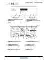
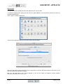
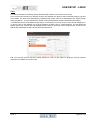
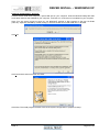
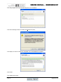
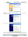
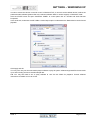
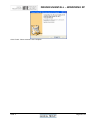
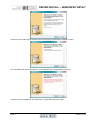
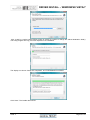
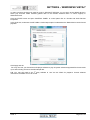
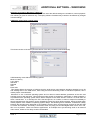
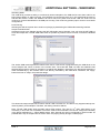
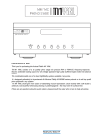
Instructions for use
Thank you for purchasing the Musical Fidelity M1 SDAC.
The M1 SDAC consists of a 32 bit DAC and a sample rate converter which asynchronously up-samples all incoming
data rates to 192 kHz. This moves the digital artefacts to well outside the audio band, allowing easy removal without
detriment to the top end of the audio band. Our well tuned filtering circuit gives immeasurably small jitter, noise and
distortion artefacts allowing astounding imaging, detail and transparency, to deliver all music types exactly as the
artist originally intended. This new design now takes into account different sampling frequencies with the upper audio
bandwidth now extending to 90 kHz for 192 kHz natively sampled input signals.
The M1 SDAC fully asynchronous USB input copes with files up to 24-bit 192 kHz sample rate input. This takes full
advantage of the higher quality recordings now available. It works with personal computers running Microsoft
Windows®, Linux and Apple® OS.
An aptX® capable Bluetooth A2DP receiver has been included. aptX® is a high quality Bluetooth link. It features full
bandwidth sound, for wireless connection to Bluetooth-capable products, such as mobile phones, computers, etc.
The Bluetooth receiver is also backward-compatible with non-aptX® Bluetooth devices.
M1 SDAC has been carefully designed to be partnered with other M1, M3 and M6 products. It also matches well with
M8 and M1 series products. Using any of these combinations will yield one of the best high-fidelity systems available
at any price.
Used carefully, it should give many years of outstanding musical reproduction.
Dust regularly with a soft duster or soft brush, but be careful when using cleaning or polishing agents - they may
harm the surface finish.
If there are any questions about the audio system, please consult the dealer who is there to help and advise.
CONTENTS
Section
Page
Safety Information
–
Mains plug (UK only), modification warning
4
General advice
–
Installation precautions
5
Disposal information
–
EU disposal information
6
Installation
–
Introduction, cleaning, installation, power connections, audio
connections, digital connections
7
Facilities and connections
–
Illustrations - main unit front & rear panels
8
Remote
–
Remote control information
9
Operation
–
Switch on and operation
10
–
Analogue inputs and outputs
11
–
Digital inputs
12
–
Digital outputs and analogue to digital conversion
13
–
Bluetooth
14,15
–
USB input
16
–
Rename inputs
Apple OS X®
–
USB Setup
19
Linux
–
USB Setup
20
Windows® XP
–
Service Pack 3
21
–
Driver install
–
Settings
–
Driver Uninstall
28-29
–
Driver install
30-33
–
Settings
34
–
Uninstall
35-36
All Windows® OS
–
Additional Settings
37-39
Problems?
–
Basic fault finding
40
Specifications
–
Unit specifications
41
–
Bluetooth antenna
42
–
Version and publication
43
Windows® Vista and 7
Manual history
Issue 4
17,18
22-26
27
Page 3 of 47
SAFETY INFORMATION
IMPORTANT! (U.K. only)
This unit is supplied in the U.K. with mains lead fitted with a moulded 13 amp plug. If, for any reason, it is
necessary to remove the plug, please remove the fuse holder and dispose of the plug safely, out of reach of
children.
It must not be plugged into a mains outlet.
The wires in the mains lead supplied with this appliance are coloured in accordance with the following code:
Green and yellow .............................Earth
Blue................................................ Neutral
Brown ..................................................Live
WARNING – This appliance MUST be earthed
As the colours of the wires of the mains lead of this appliance may not correspond with the coloured markings
identifying the terminals in the plug, proceed as follows:
•
The wire which is coloured green-and-yellow must be connected to the terminal in the plug which is marked
with the letter E or coloured green or green-and-yellow, or by the earth symbol:
•
The wire which is coloured brown must be connected to the terminal which is marked with the letter L or
coloured red.
•
The wire which is coloured blue must be connected to the terminal which is marked with the letter N or
coloured black.
•
If connecting to a BS1363 plug, a 13 amp fuse must be used.
WARNING:
ANY MODIFICATIONS TO THIS PRODUCT NOT EXPRESSLY
APPROVED BY MUSICAL FIDELITY WHO IS THE PARTY RESPONSIBLE
FOR STANDARDS COMPLIANCE COULD VOID THE USER'S
AUTHORITY TO OPERATE THIS EQUIPMENT.
Issue 4
Page 4 of 47
GENERAL ADVICE
Installation, Precautions & User Information
This new M1 SDAC is designed and built to provide trouble-free performance, but as with all electronic devices
it is necessary to observe a few precautions:
•
Heed all warnings shown on the back of the product.
•
Only connect the M1 SDAC to a mains outlet having the same voltage as marked at the back of the unit.
•
Always ensure that when disconnecting and reconnecting your audio equipment the mains supply is
switched off.
•
Position the mains lead and signal interconnects where they are not likely to be walked on or trapped by
items placed on them.
•
Do not use near water, or place water-filled containers on the M1 SDAC, for example, a flower vase or
potted plants. If water does spill inside, immediately pull out the mains plug from the wall socket and
inform the dealer, who should then check the unit before further use. Entry of liquid into the M1
SDAC is dangerous, and may cause electric shock or fire hazard.
•
Do not place the unit near direct heat sources such as radiators, direct sunlight or other equipment.
•
Do not remove any covers or try to gain access to the inside. There are no user adjustments or fuses to
change without qualification. Refer all service work to an authorised Musical Fidelity agent.
* Note: Unauthorised opening of the equipment will invalidate any warranty claim.
•
Before cleaning the unit, switch off power at the mains switch and remove the mains plug from the wall
socket .Dust regularly with a soft cloth or soft brush but be careful when using cleaning or polishing agents they may harm the surface finish.
The electronics in modern hi-fi equipment is complex and may, therefore, be adversely affected or damaged by
lightning. For protection of the audio system during electrical storms, remove the mains plugs.
If after-sales service is required, to help the dealer identify the M1 SDAC please quote the serial number located
on the rear panel of the unit.
Issue 4
Page 5 of 47
ITEM DISPOSAL INFORMATION
DISPOSAL
The crossed out wheeled bin label that appears on the back panel of the product indicates that
the product must not be disposed of as normal household waste. To prevent possible harm to the
environment please separate the product from other waste to ensure that it can be recycled in an
environmentally safe manner. Please contact local government office or retailer for available collection
facilities.
DISPOSITION
La poubelle sur roulettes barrées X, qui apparaît en logo sur le panneau arrière du produit, indique que celui-ci ne
doit pas être traité comme un déchet domestique commun. Afin de protéger l'environnement, ce produit électronique devra
être géré séparément et donc recyclé selon les nouvelles normes Européennes Rohs concernant les déchets d'appareils
électroniques. Prière de contacter les services concernés gouvernementaux ou votre point de vente pour l'élimination et
l'enlèvement de déchets électroniques équipés de composants électroniques.
DISPOSAL
La etiqueta cruzada hacia fuera del compartimiento que aparece en el panel trasero del producto indica que el
producto no se debe reciclarse como basura normal de la casa. Para prevenir daños posible al ambiente separe por favor el
producto de otras basura para asegurarse de que puede ser reciclada de una manera ambientalmente segura. Entre en
contacto por favor a su oficina gubernamental local o a su minorista para las instalaciones disponibles de la colección.
RIFIUTI
L'etichetta del cassonetto barrato riportato sul retro dell'apparecchio indica che il prodotto non deve essere
smaltito tramite la procedura normale di smaltimento dei rifiuti domestici. Per evitare eventuali danni all'ambiente, separare
questo prodotto da altri rifiuti domestici in modo che possa venire riciclato in base alle procedure di rispetto ambientale. Per
maggiori dettagli sulle aree di raccolta disponibili, contattate l'ufficio govenativo locale od il rivenditore del prodotto.
FACHGERECHTE ENTSORGUNG:
Das auf der Geräterückseite angebrachte Label deutet darauf hin, dass das Produkt nicht mit konventionellem
Hauskehricht entsorgt werden darf. Um Schäden und Verschmutzungen an Umwelt und Mensch zu vermeiden, muss das
Produkt fachgerecht entsorgt und von anderem Abfall getrennt werden. Wenden Sie sich bei Fragen hierzu an Ihren
Fachhändler oder an eine öffentliche Informationsstelle.
AFVAL
Het label op de achterzijde van dit apparaat, een afvalbak op wielen met een kruis doorgehaald, geeft aan dat dit
apparaat niet samen met gewoon huishoudafval mag worden weggegooid. Om mogelijke schade aan onze leefomgeving te
voorkomen dient dit apparaat, gescheiden van gewoon huishoudelijk afval, te worden afgevoerd zodat het op een
milieuvriendelijke manier kan worden gerecycled. Neem voor beschikbare inzamelplaatsen contact op met uw gemeentelijke
reinigingsdienst of met uw elektronica leverancier.
HÄVITTÄMINEN
Yliruksattua jäteastiaa kuvaava tarra tuotteen takalevyssä kertoo, että tuotetta ei saa käsitellä normaalina
talousjätteenä. Ympäristön suojelemiseksi on tuote pidettävä erillään muusta jätteestä ja se on kierrätettävä ekologisesti
kestävällä tavalla. Ota yhteyttä laitteen myyjään tai Pirkanmaan Ympäristökeskukseen lähimmän kierrätyskeskuksen
löytämiseksi.
AFSKAFNING
Logoet med en skraldespand med kryds over på bagsiden af apparatet indikerer at dette produkt ikke må kasseres
som normal husholdningsaffald. For at forebygge mulig skade på miljøet, bedes De separere dette produkt fra andet affald,
og sikre at det bliver genbrugt på en miljørigtig måde. Kontakt venligst de lokale myndigheder eller din forhandler for
oplysning om nærmeste tilgængelige opsamlingssted for elektronikaffald.
ΔΙΑΔΙΚΑΣΙΑ ΑΠΟΡΡΙΨΗΣ
ΤΟ ΣΗΜΑ ΜΕ ΤΟΝ ΔΙΑΓΕΓΡΑΜΜΕΝΟ ΤΡΟΧΗΛΑΤΟ ΚΑΔΟ ΑΠΟΡΡΙΜΑΤΩΝ ΣΤΗΝ ΠΙΣΩ ΟΨΗ ΤΟΥ
ΜΗΧΑΝΗΜΑΤΟΣ
ΔΗΛΩΝΕΙ ΟΤΙ ΤΟ ΠΡΟΙΟΝ ΑΥΤΟ ΔΕΝ ΠΡΕΠΕΙ ΝΑ ΔΙΑΧΕΙΡΙΣΘΕΙ ΣΑΝ ΣΥΝΗΘΙΣΜΕΝΟ ΟΙΚΙΑΚΟ ΑΠΟΒΛΗΤΟ.
ΠΡΟΣ ΑΠΟΦΥΓΗ ΕΝΔΕΧΟΜΕΝΗΣ ΕΠΙΒΑΡΥΝΣΗΣ ΤΟΥ ΠΕΡΙΒΑΛΛΟΝΤΟΣ, ΞΕΧΩΡΙΣΤΕ ΤΟ ΠΡΟΙΟΝ ΑΠΟ ΤΑ ΑΛΛΑ
ΑΠΟΡΡΙΜΑΤΑ ΩΣΤΕ ΝΑ ΕΞΑΣΦΑΛΙΣΘΕΙ Η ΑΝΑΚΥΚΛΩΣΗ ΤΟΥ ΜΕ ΤΟΝ ΠΡΕΠΟΝΤΑ ΤΡΟΠΟ.
ΠΑΡΑΚΑΛΟΥΜΕ ΝΑ ΕΠΙΚΟΙΝΩΝΗΣΕΤΕ ΜΕ ΤΗΝ ΤΟΠΙΚΗ ΥΠΗΡΕΣΙΑ ΑΝΑΚΥΚΛΩΣΗΣ Η ΜΕ ΤΟ ΚΑΤΑΣΤΗΜΑ ΑΓΟΡΑΣ
ΓΙΑ ΠΕΡΙΣΣΟΤΕΡΕΣ ΛΕΠΤΟΜΕΡΕΙΕΣ.
Issue 4
Page 6 of 47
INSTALLATION
Introduction
Congratulations on the purchase of the new M1 SDAC. This unit will deliver the ultimate performance possible
from any digital source. It is designed to upgrade CD players, TVs, set-top-boxes, DAB tuners, and any other
source providing a variety of digital outputs.
Installation
Position the M1 SDAC on a stable, horizontal surface where there is no risk of it being knocked, or subjected to
vibration such as from loudspeakers.
Important note: In normal operation, the unit dissipates a small quantity of power at all times, and it is
important that it is adequately ventilated. The M1 SDAC must be protected from humidity – if the unit is
moved from a cold place to a warm room, leave the unit for an hour or so to allow sufficient time for the
moisture to evaporate.
Power Connections
The M1 SDAC is supplied with a standard IEC mains cable which plugs into the IEC socket at the back of the
unit.
Audio input connections
RCA audio inputs AUX 1, AUX 2: Use good quality shielded RCA phono audio cables (fully connected at both
ends - signal and ground), for optimum signal transfer.
Audio output connections
RCA audio outputs: Use good quality shielded RCA phono audio cables (fully connected at both ends - signal
and ground), for optimum signal transfer.
HEADPHONES output: Use good quality headphones for private listening.
Digital input connections
COAXIAL inputs: Connect RCA digital source to digital input RCA sockets 1, 2 or both. Use a good quality fully
connected (signal and ground) coaxial digital cable, for optimum signal transfer.
AES BALANCED input: Connect AES/EBU digital source to balanced digital input XLR socket. Use a good
quality balanced DIGITAL cable, for optimum signal transfer. Recommended wiring is given on P.7
OPTICAL input: Connect optical digital source to optical input socket. Use a good quality “Toslink” cable, for
optimum signal transfer.
Note: If connecting to Home Theatre Processor, TV or DVD, Blue-Ray, or similar Home Theatre digital
sources, it may be necessary to change the digital output of the source to “16 bit stereo PCM”, or similar, which
is the format the M1 SDAC will understand. Please refer to the source’s manual for information on how to do
this. The M1 SDAC does not recognise the information in multichannel (surround sound) digital audio streams.
USB input: Connect computer or similar USB “host” source to USB input socket. Use a good quality USB 2.0
“A to B” type cable (not supplied), for optimum signal transfer. Try to keep USB cable length to a minimum for
best reliability. The USB 2.0 standard maximum for a single cable is 5M, after which repeaters (normally mainspowered USB hubs) are required. We do however; recommend avoiding such a setup if at all possible and
keeping the USB lead length to the absolute minimum possible for the setup.
Digital output connections
COAXIAL output: Connect RCA digital receiver or digital recording device to digital output RCA socket. Use a
good quality fully connected (signal and ground) coaxial digital cable, for optimum signal transfer.
OPTICAL output: Connect optical digital receiver or digital recording device to digital output optical socket. Use
a good quality “Toslink” cable, for optimum signal transfer.
Trigger Connections
Trigger input: Connect system triggering device output to this socket. Use good quality 3.5mm mono jack
cable. Unit accepts 4.5V-15V DC triggering, either polarity.
Trigger output: Connect further devices in the system to be triggered into this socket. Use good quality 3.5mm
mono jack cable. Unit passes on +12V DC at up to 60mA, for further devices.
Interconnects
Please note: Musical Fidelity currently do not make any interconnecting cables other than those supplied with
the unit. Musical Fidelity does not endorse any other manufacturer’s cables.
If necessary, please refer to the dealer who can advise on quality cables for any particular setup.
Issue 4
Page 7 of 47
FACILITIES & CONNECTIONS
2
1
3
4
5
1
POWER Mains ON/STBY button and LEDs
4
IR remote control sensor lens
2
DISPLAY Window
5
3
ROTARY CONTROL volume and input
select
HEADPHONE ¼”/5.25mm stereo Jack
socket
6
7
11
12
13
8
14
15
16
9
17
18
10
19
6
BLUETOOTH RP-SMA antenna socket
13 RCA PRE OUTPUTS left and right
7
USB asynchronous digital input
14 OPTICAL digital output
8
AES BALANCED digital input
15 COAXIAL digital output
9
TRIGGER in 3.5mm mono jack
16 OPTICAL digital input
10 TRIGGER out 3.5mm mono jack
17 COAXIAL digital input 1
11 AUX 1 analogue input left and right
18 COAXIAL digital input 2
12 AUX 2 analogue input left and right
19 MAINS IEC socket
Issue 4
Page 8 of 47
REMOTE CONTROL HANDSET
The universal remote control shown below enables functions from this and related units to be operated from a
convenient distance.
Equivalent buttons on the remote control have the same functions as those on the front panel of the unit. Other
functions are only available by remote control.
As the handset uses an invisible infra-red light beam, the front edge must be pointed directly towards the
receiver window at the front of the player, without visual obstruction between them.
If the range of the remote control greatly decreases, replace the batteries with new ones. Do not mix old and
new batteries – two are required, size AAA, LR03 or SUM-4.
Please dispose of used batteries in accordance to local battery disposal regulations.
DAC – blue buttons + red power
CD player – grey buttons
POWER On or standby DAC only
MUTE - mutes DAC outputs
0-9 Buttons – Used to select track
numbers on CD player
(until pressed again).
BLUETOOTH – select DAC Bluetooth
receiver
USB-192 – selects DAC USB input
COAX1 – selects COAX1 input
COAX2 – selects COAX2 input
OPTICAL – selects optical input
AES - selects balanced digital input
VOLUME + Increases volume
VOLUME – Decreases Volume
SCAN – plays first 10 seconds of each
track
A/B sets repeat start/end to repeat
section of track
REPEAT – repeats whole disk or selected
tracks
SHUFFLE – plays back tracks in
random order
SEARCH – fast forward/backward through
track
TRACK │◄◄ – previous track
STOP – Stop playing CD completely
TRACK ►►│ – next track
PAUSE││– pause CD playback
PLAY ►– start CD playback
Issue 4
Page 9 of 47
SWITCH ON AND OPERATION
Once the M1 SDAC unit is correctly wired up, and plugged into mains, the orange STBY led should be lit.
In this mode the M1 SDAC is consuming a minimal amount of power. It may be left in this state indefinitely
without harm.
To switch the unit on, press the POWER STBY button so the blue POWER LED is lit.
The display should also come on, in a similar sequence to below:
Musical Fidelity
Product name and firmware version.
M1 SDAC
V. 1.00
Volume setting briefly flashed up (volume is always remembered from last time it was switched on, even if
mains is unplugged)
42.0
Unit settles displaying current input (input is remembered from last time it was switched on, even if mains is
unplugged)
AUXILIARY 1
Analogue
Rotary Control - As Volume
Turning the rotary control changes the volume accordingly. The display shows both a numeric setting and bar
graph indicating current volume setting. Volume + and - buttons on remote perform the same function.
Adjustment is in 0.5dB steps for single presses and speeds up if button is held down. The setting is
remembered if switching off and on again.
©
45.5
Changing the selected input:
Rotary Control – As input selector
Pressing the rotary selector in enters the "select input" menu. This menu allows one to select an input from a
list. A tick is shown next to the currently selected input.
√AUXILIARY 1
Rotating the selector allows one to see the list of possible inputs. A flashing square indicates the current option.
N.B. Selecting "EXIT" in this menu will exit without changing the currently selected input.
©BLUETOOTH
To select a particular input, rotate the selector until the desired input is shown on the top line
alongside the flashing square and press the selector knob. The example above shows that the Bluetooth input is
being selected.
BLUETOOTH
No Link
The unit will switch over to the chosen input and the display will confirm it. The setting is remembered if
switching off and on again.
Issue 4
Page 10 of 47
ANALOGUE INPUTS & OUTPUTS
AUX 1 input
To use the AUX1 input, press AUX 1 on the remote control.
To select from the front panel, press the volume control in to access the source select menu and rotate control
until AUXILLIARY 1 is next to the flashing square.
Note: Currently set input is indicated by a tick, which in the example below is AUX 2
√AUXILIARY 2
Then press the volume control to confirm the input. The screen will change to show the new selected input.
AUXILIARY 1
Analogue
AUX 2 input
To use the AUX2 input, press AUX 2 on the remote control.
To select from the front panel, press the volume control in to access the source select menu and rotate control
until AUXILLIARY 2 is next to the flashing square.
©AUXILIARY 2
Then press the volume control to confirm the input. The screen will change to show the new selected input.
AUXILIARY 2
Analogue
The chosen input is remembered even if the mains is removed
Outputs Headphones and PRE-OUTs
When headphones are plugged in, the PRE OUTS will mute (effectively muting signal to speakers) and unit will
switch to a different stored volume setting.
This new setting is in operation for as long as the headphones remain plugged in. The volume may therefore be
independently set for comfortable headphone listening.
Once the headphones are removed, the preamp outputs are restored and volume is reset to the previous level.
The headphone volume level is also stored for next time headphones are plugged in.
The two level settings are remembered even if the mains is removed
Issue 4
Page 11 of 47
DIGITAL INPUTS
COAXIAL1 input
To use the COAXIAL 1 input, press COAX 1 button on the remote control.
To select from the front panel, press the volume control in to access the source select menu and rotate control
until COAXIAL 1 is next to the flashing square. Then press the volume control to confirm the input. The screen
will change to show the new selected input.
COAXIAL 1
44.1kHz
>
192kHz
With valid SPDIF signal present on a selected digital input the unit will show the incoming sampling rate and that
it is being internally up sampled to 192 kHz.
COAXIAL2 input
To use the COAXIAL 2 input, press COAX 2 button on the remote control.
To select from the front panel, press the volume control in to access the source select menu and rotate control
until COAXIAL 2 is next to the flashing square. Then press the volume control to confirm the input. The screen
will change to show the new selected input.
COAXIAL 2
44.1kHz
>
192kHz
With valid SPDIF signal present on a selected digital input the unit will show the incoming sampling rate and that
it is being internally up sampled to 192 kHz.
Both coaxial inputs are capable of accepting up to 24 bit 192 kHz PCM stereo data streams.
N.B. For devices with “Surround Sound” digital outputs, it may be necessary to set such device outputs to “2
channel” or “stereo” PCM or similar in order to pass on the correct stream to the M1 SDAC.
AES BALANCED input
To use the AES BALANCED input, press AES button on the remote control.
To select from the front panel, press the volume control in to access the source select menu and rotate control
until COAXIAL 1 is next to the flashing square. Then press the volume control to confirm the input. The screen
will change to show the new selected input.
AES BALANCED
44.1kHz
>
192kHz
With valid SPDIF signal present on a selected digital input the unit will show the incoming sampling rate and that
it is being internally up sampled to 192 kHz.
AES balanced input is capable of accepting up to 24 bit 192 kHz PCM stereo data streams.
N.B. For devices with “Surround Sound” digital outputs, it may be necessary to set such outputs to “2 channel”
or “stereo” PCM or similar to pass on the correct stream to the M1 SDAC.
OPTICAL input
To use the OPTICAL input, press OPTICAL button on the remote control.
To select from the front panel, press the volume control in to access the source select menu and rotate control
until OPTICAL is next to the flashing square. Then press the volume control to confirm the input. The screen will
change to show the new selected input.
OPTICAL
44.1kHz
>
192kHz
With valid SPDIF signal present on a selected digital input the unit will show the incoming sampling rate and that
it is being internally up sampled to 192 kHz.
The OPTICAL input is capable of accepting up to 24 bit 96 kHz PCM stereo data streams. The incoming data
sample rate is accurately displayed on screen for reference.
N. B. For devices with “Surround Sound” digital outputs, it may be necessary to set such outputs to “2 channel”
or “stereo” PCM or similar to pass on the correct stream to the M1 SDAC.
Issue 4
Page 12 of 47
DIGITAL OUTPUTS
Digital Outputs and Analogue to Digital Conversion.
ANALOGUE inputs are converted to digital internally by an analogue to digital converter. This allows the
passing on of the selected ANALOGUE input signals to another DAC, processor, or recording unit digitally. The
unit may therefore be used as an analogue to digital converter, passing on the ANALOGUE as well as DIGITAL
input signal to another DAC, processor, or recording unit digitally.
The Digital output sockets all pass the DIGITAL input signal from digital optical/coaxial SPDIF or USB inputs at
the same sample rate as it comes into the DAC. This means the digital outputs are not up sampled or
reprocessed in any way.
The level of the digital outputs is not affected by the volume control.
The Bluetooth digital output is also available when selected, and is output at 96 kHz.
The USB digital output is also available when selected, and is output at native (original input) rate.
N. B. M1 S-DAC USB socket functions as digital input ONLY. No digital audio output signals are available from
the USB socket.
Note: The SPDIF coaxial and AES (XLR) outputs are capable of up to 192 kHz 24 bit signals.
- The optical output however can only output signals up to 96 kHz. If input signal greater than 96 kHz is present,
there will be no output from the optical output.
Issue 4
Page 13 of 47
BLUETOOTH
The M1 SDAC features a Bluetooth A2DP audio input (receiver circuit). This can be used to
receive Bluetooth transmissions from other Bluetooth Audio (A2DP) enabled devices such as
mobile phones, laptop computers or similar Bluetooth enabled sources. If the connecting device
supports aptX®, the M1 SDAC will use it.
Bluetooth is a digital “radio” link and as such requires an external antenna to function. This antenna is supplied
with the M1 SDAC. Consult the reseller/dealer if the antenna is missing.
BLUETOOTH antenna
M1 SDAC is housed in a top quality metal enclosure and therefore requires an external antenna for Bluetooth
operation. Bluetooth is unlikely to work at all without the antenna attached!
The Bluetooth antenna should either be attached directly to the socket on the back of the unit. For better
positioning flexibility, the antenna may be attached to its magnetic base which, is then attached to the antenna
socket on the back of the unit.
When positioning the antenna, ensure it is away from potential sources of interference, and in full, plain view
from across the room.
When making connections, please ensure the nuts are tightened to “finger-tight” and as such be secure.
It is neither necessary nor recommended to use tools to tighten them any further!
BLUETOOTH device setup
To create a Bluetooth link it is necessary to “pair” and then “connect” the Bluetooth device(s) to the M1 SDAC.
This needs to be done every time a new device is introduced to the M1 SDAC.
The M1 SDAC stores information for up to 16 Bluetooth devices.
The M1 SDAC must be turned on; with blue POWER LED and display lit (it is not actually necessary to switch to
Bluetooth input at this point, but it is easier to see when a valid link is established). The display will show no link.
This means that the unit does not yet recognize any Bluetooth device in the vicinity.
BLUETOOTH
No Link
Please consult and follow the device (phone, etc) manual instructions for pairing.
You do not need to do anything on the M1 SDAC other than ensure it is ON.
If the DAC is not listed, try refreshing the list in the Bluetooth device, and check that the M1 SDAC is on (i.e. not
in standby). Also check antenna is fitted; positioned away from potential sources of interference, and in full,
plain view from across the room.
“Pair” (see device user manual for more details) with the “Musical Fidelity M1 SDAC” that should appear in the
device’s Bluetooth list.
N.B. If asked for a password, please enter “1234” on the phone. This password is not changeable.
“Connect” (see device user manual for more details) with the “Musical Fidelity M1 SDAC” that should appear in
the device’s Bluetooth list.
The device should then be “connected”. Successful connection is indicated by the word “Linked” as shown in
the example below.
BLUETOOTH
44.1kHz
>
192kHz
BLUETOOTH input
To use the BLUETOOTH input, press the BLUETOOTH input select button on the front panel, or remote
control.
The incoming sample rate will be displayed if a valid digital signal is present.
BLUETOOTH
44.1kHz
>
Issue 4
192kHz
Page 14 of 47
BLUETOOTH
aptX® audio (automatic)
If aptX is available on the connecting device, the M1 SDAC will automatically implement it for best audio quality.
To check if the connecting device supports aptX® please consult the device manuals/support.
No user intervention on the M1 SDAC is possible and the setting is entirely automatic.
BLUETOOTH
44.1kHz
>
aptX
192kHz
The Bluetooth input is capable of accepting up to 16 bit 48 kHz PCM stereo data streams. The incoming data
sample rate is accurately displayed on screen for reference.
Caution: If changing the Bluetooth link sample frequency from the transmitting device, e.g. computer, it is
highly recommended to first disconnect/unpair the two Bluetooth devices before making the changes. Once the
change has been made, simply reconnect/pair the two devices and carry on using as normal.
Disconnecting Bluetooth device(s)
To disconnect the M1 SDAC from the Bluetooth device press and hold the Bluetooth button Until the display
shows
Forget all devs?
Confirm: OK
to cancel disconnection press any button or to continue with disconnecting press OK or press volume control in.
All devs removed
The M1 SDAC will prompt if the device is to be “Forgotten” or not. This is best used to forget devices that are
not likely to be used again with the M1 SDAC. Up to 16 devices can be remembered so there is plenty of space
for different devices under normal use.
Disconnect Link?
Confirm: OK
Press OK or volume knob to disconnect the link, any other key to cancel forgetting device (i.e. remember it).
Forgetting the device briefly shows
Now disconnected
before returning to the Bluetooth input screen.
BLUETOOTH
Fixed
No Link
BLU
To “forget” all stored Bluetooth devices, press and hold the Bluetooth button when the above screen is
displayed.
Forget device?
Confirm: OK
Press OK or volume knob to forget the device, any other key to cancel forgetting device (i.e. remember it).
Device removed
before returning to the Bluetooth input screen.
Issue 4
Page 15 of 47
USB INPUT
USB input
To use the USB input, press the USB input select button on the front panel, or remote control.
USB 192
48kHz
>
192kHz
The USB input is capable of accepting up to 24 bit 192 kHz USB data streams. The incoming data sample rate
is accurately displayed on screen for reference.
N.B. This shows the actual raw sample rate of the digital data going into the M1 SDAC; which is not necessarily
the same as the original source material sample rate as stored on the computer. Also computer software and
settings can dictate actual sample rate coming from computer USB port. Please refer to computer or software
documentation for best advice on setting up.
Computer settings for USB
A good quality USB 2.0 A to B cable is required to connect the unit to the computer. Normal USB standards
stipulate that this should be 5M or less; and we recommend keeping it as short as possible.
Plug the B (square) end into the socket in the back of the unit, and the A (rectangle) end into a free USB socket
on the computer.
The computer should now detect the new hardware:
Linux kernel 2.6.33 or later see P.20
Apple OS X® 10.6.4 or later see P.19
No other drivers are required for the above operating systems.
For PCs running Widows XP, Vista and 7, a driver disk (CD) is required. This is supplied with the M1 SDAC.
Consult the reseller/dealer if the driver disk (CD) is missing.
Windows® XP (SP3) see P.22 (p. 21 if Windows® XP does not have Service Pack 3 installed).
Windows® Vista, 7 or later see P.30
Earlier operating systems are not supported.
Additionally, the use of third party software such as “ASIO” or similar is not supported by Musical Fidelity. In
case of difficulty with any of these software types, please consult the relevant software documentation and/or its
support services.
CD, MP3, WAV, AAC/+, OGG, FLAC, and any other audio file types played on suitable playback software
should now play through the unit.
Please note: This USB input has a high speed serial data processor, and by its nature, requires a very high
volume of USB band width. It will benefit greatly from being the only device connected on its USB ‘bus’. Sharing
the same bus with other devices include could cause unwanted artifacts such as dropouts or temporary loss of
signal. This especially includes the use of the unit on a USB hub/splitter whether alongside other USB
components or not. A direct connection to the host computer by shortest USB 2.0 lead possible is very much
recommended.
Issue 4
Page 16 of 47
RENAMING INPUTS
Renaming an input
For further convenience the inputs may be renamed to suit the particular setup; and make choosing the right
input easier. All inputs can be renamed with custom names up to 16 characters (including symbols and spaces).
To rename an input, enter the "select input" menu by pressing the selector knob. The renaming feature uses
the M1 SDAC remote CD player section grey buttons in addition to the blue DAC buttons.
Rotate the selector knob to show the input to be renamed opposite the blinking cursor on the top line of the
display.
©AUXILIARY 1
Then press the ◄ or ► button on the remote controller.
RENAME INPUT
AUXILIARY 1
AUXILIARY 1
©
The default name of the input will be shown in the top line of the display. Using the remote numeric keypad, the
input can then be given a new name.
Input the letters/characters desired by pressing the alphanumeric keys on the M1 SDAC remote. Pressing the
“2” button once, for example produces
AUXILIARY 1
A
and then quickly pressing “2” button twice more gives
AUXILIARY 1
C
after a short pause, the cursor moves over ready for next letter input.
COAXIAL 1
All the number keys 0-9 function in a similar manner to produce the required letters, numbers and selected
characters as indicated on and above the keys.
Note: SPACE is the 1st character on the “1” button!
COAXIAL 1
CDD
To delete an incorrect character use the ◄ button. The cursor jumps back a character automatically clearing the
character that was there before, ready for a new character to be input.
COAXIAL 1
CD
For lower case letters, press ▲ button. This button has a “toggle” action, so to revert to upper case, simply
press it once again
COAXIAL 1
CD Player
Once the complete name has been typed in, confirm the new text by pressing OK on the remote or pressing the
selector knob.
Issue 4
Page 17 of 47
RENAMING INPUTS
Input renamed
Unit will then return to the "select input menu" where the new name of the input will be displayed.
The renamed input(s) now display the stored name. To rename another input, select that input and repeat the
above process. To change the name of an existing renamed input, simply repeat the above process.
CD Player
Analogue
Note: The input names are stored indefinitely; even if unit is switched off and unplugged.
Note: if a Musical Fidelity CD player/transport is present: RENAME INPUTS function uses existing CD player
codes to “type in” the desired name. To prevent nearby CD player(s) from responding to remote commands,
please make sure any remaining disk is fully removed during “rename” process. Alternatively switch the CD
player off. This will prevent random tracks from being played while renaming the input.
If left on, the CD player display will respond to the key presses. This is normal, will not harm the CD player and
may be ignored.
Once the renaming process is complete, the CD may be reinserted into the player and/or the player turned
back on again. The CD player may now be used as normal.
Factory state
The M1 SDAC can be reset to factory default. This makes it easy to reset all input names and all level-matched
input settings, as well as erase the paired Bluetooth devices list.
This is implemented by switching to standby, removing mains plug from back. The power on button should then
be held down while the mains plug is re-inserted. When the display is lit up, release the power on button.
Factory reset?
Confirm: OK
Press any key to cancel reset factory state or press OK/front panel control to reset all the settings to factory
state. Reset factory state briefly shows
Resetting ...
System is now reset
then the unit switches to standby. All settings, names and Bluetooth devices have now been erased.
To switch back on again, press the power/standby button as normal.
Issue 4
Page 18 of 47
USB SETUP - APPLE OS
Apple OS X®
This product has been tested and works with Apple OS X® 10.6.4 or later.
To install into Apple OS X® simply plug the unit into a spare USB port. The unit will then need to be chosen as
the default audio device.
Go to “Apple”, “System preferences”
“Sound”, then Output tab to get to the sound window as shown below.
Select the MF USB 2.0 Audio Out entry as your output device. The MF USB Audio output is now ready for use
with your favourite media player software.
N.B. You may still need to set 3rd party software to “use” the M1 SDAC for playback. Consult software
instructions for details on how to do this.
Issue 4
Page 19 of 47
USB SETUP - LINUX
Linux
This device has been successfully set up and tested with Ubuntu Linux kernel 2.6.33 or later.
Linux is open source and many different versions are available, the latest of which inherently support 192 kHz
24 bit audio. The drivers are automatically installed (other and/or older Linux distributions may require further
setup procedures – for such distributions, please consult the distribution support website/documentation).
To enable the device as the default output player, it is necessary to set it up as such in the Sound dialogue box.
To do this, click on the speaker icon in the top taskbar, and then click on “Sound settings”. The box below will
appear. Select the “Output” tab and highlight the MF USB 2.0 Audio Out as the output device. Close the box
and the MF USB Audio out will now play all sounds and music.
N.B. You may still need to set some media software to “use” the M1 SDAC for playback. Consult software
instructions for details on how to do this.
Issue 4
Page 20 of 47
SERVICE PACK 3 FOR WINDOWS® XP
Service Pack Requirements for Microsoft Windows® XP
This product will work with Windows XP installations that have been updated to SERVICE PACK 3 (also
known simply as “SP3”).
If you already have Windows® XP Service Pack 3 installed you may skip this section and go on to next page
“Installing the Windows® XP driver”.
To check service pack updates, click on start button, click on “RUN” then type “winver” in the “OPEN” box.
Click “OK”. A dialogue box similar to the one below indicates service pack 3 is indeed installed by the line
stating “Version 5.1 (Build 2600,xpsp_3_gdr.101209-1647: Service Pack 3)”
If service pack 3 is not installed please use the Microsoft Updates feature, website, or consult your computer
dealer.
Please note that, at time of writing, it is absolutely vital you have Service Pack 2 installed before
attempting to install service pack 3!
Issue 4
Page 21 of 47
DRIVER INSTALL – WINDOWS® XP
Installing the Windows® XP driver
Connect the MF USB Audio output to a spare USB port on your computer. Insert the Musical Fidelity MF USB
Audio driver disk into the CDROM of your computer. It will auto run, if CD auto run is enabled on your computer.
Note: If for any reason it does not auto run, use Windows® explorer or My Computer to find your CD ROM
(often D:). Open the CDROM by double clicking it, and then double click on MF-USB-192-V1.56.EXE
Click Yes
Click Yes and the welcome screen will show:
Click Next. The install program will take a look at the system configuration to prepare for setup
Issue 4
Page 22 of 47
DRIVER INSTALL – WINDOWS® XP
If for any reason the unit is not plugged in or not detected, the message below will pop up.
Check the device is plugged in (and switched on, if applicable) and press “Next”.
Click “Install” to Confirm install location (There is usually no reason to change the offered destination folder).
Issue 4
Page 23 of 47
DRIVER INSTALL – WINDOWS® XP
The setup program will copy over files required for the installation.
The below message will show. Please click Continue Anyway.
The display now shows “Setup was completed”, and “Preinstallation successful”.
Click “Next”.
The installer then shows.
Issue 4
Page 24 of 47
DRIVER INSTALL – WINDOWS® XP
Click Finish.
The necessary files have been copied and now need to be picked up by the Windows® system. A dialogue box
should shortly pop up as below
Select the 3rd option: “No, not this time”, then click “Next”.
Select “Install the software automatically (Recommended)”. Click “Next”. The “Found New Hardware Wizard”
will appear for “Musical Fidelity MF USB 2.0 Audio out”, then a sub-window “Hardware Installation” appears
Issue 4
Page 25 of 47
DRIVER INSTALL – WINDOWS® XP
Ignore the warning and press “Continue Anyway”
Windows® copies the driver files into the correct places in its system directory. When copying is completed the
following box will appear:
Click “Finish”. A pop-up on the task bar says: “Your new hardware is installed and ready to use.”
This indicates the unit has been recognised correctly by the computer and is ready for use.
Issue 4
Page 26 of 47
SETTINGS – WINDOWS® XP
In order to ensure the device is used for music in Windows® XP, it can set it as the default device in either the
preferred media software (please refer to the relevant software HELP or online support) or Windows® itself:
Click the START button and open CONTROL PANEL. In control panel click on “Sounds and Audio Devices
Properties”
In the Audio tab, make sure the MF USB 2.0 Audio Output option is selected as the Default device under Sound
playback.
Click Apply and OK.
You may now use your favourite media player software to play all system software-supported file format tracks
up to and including 24 bits at 192 kHz sample rate.
N.B. You may still need to set 3rd party software to “use” the M1 SDAC for playback. Consult software
instructions for details on how to do this.
Issue 4
Page 27 of 47
DRIVER UNINSTALL – WINDOWS® XP
Windows® XP uninstalling software
To remove the driver and its associated software, go to Windows® Control Panel.
Click on MF USB 2.0 Audio Out USB Audio Driver then click “Remove”. The uninstaller runs, showing:
Click “Uninstall”
The files are removed, click “Next”
Issue 4
Page 28 of 47
DRIVER UNINSTALL – WINDOWS® XP
Click “Finish”. Driver removal is now complete.
Issue 4
Page 29 of 47
DRIVER INSTALL – WINDOWS® VISTA/7
Installing the Windows® Vista or Windows® 7 driver
Connect the MF USB Audio to a spare USB port on your computer. Cancel the pop-up window that may appear
asking where to look for the driver. Insert the Musical Fidelity MF USB Audio driver disk into the CDROM of
your computer. It will auto run, if CD auto run is enabled on your computer.
Note: If for any reason it does not auto run, use Windows® explorer or “Computer” under Windows® button to
find your CD ROM (often D:). Open the CDROM by double clicking it, and then double click on MF-USB-192V1.56.EXE
Click “Run MF USB Audio ….”
Click “Yes”
Click “Yes”
If a “User Account Control” window pops up, asking permission to continue, please press “Continue”.
Issue 4
Page 30 of 47
DRIVER INSTALL – WINDOWS® VISTA/7
Click Next. The install program will take a look at the system configuration to prepare for setup
If for any reason the unit is not plugged, in or not detected, the message below will pop up
Check the device is plugged in (and switched on, if applicable) and press “Next”.
Issue 4
Page 31 of 47
DRIVER INSTALL – WINDOWS® VISTA/7
Click “Install” to confirm install location.(There is usually no reason to change the offered destination folder).
The setup program will copy over files required for the installation.
The display now shows “Setup was completed”, and “Preinstallation successful”.
Click “Next”. The installer then shows.
Issue 4
Page 32 of 47
DRIVER INSTALL – WINDOWS® VISTA/7
Click “Finish”. A pop-up on the task bar says: “Your new hardware is installed and ready to use.”
This indicates the unit has been recognised correctly by the computer and is ready for use.
Issue 4
Page 33 of 47
SETTINGS – WINDOWS® VISTA/7
In order to ensure the device is used for music in Windows® XP/Vista, you can set it as the default device in
either your favourite media software (please refer to the relevant software HELP or online support) or
Windows® itself:
Click the START button and open CONTROL PANEL. In control panel click on “Sounds and Audio Devices
Properties”
In the Audio tab, make sure the MF USB 2.0 Audio Output option is selected as the Default device under Sound
playback.
Click Apply and OK.
You may now use your favourite media player software to play all system software-supported file format tracks
up to and including 24 bits at 192 kHz sample rate.
N.B. You may still need to set 3rd party software to “use” the M1 SDAC for playback. Consult software
instructions for details on how to do this.
Issue 4
Page 34 of 47
UNINSTALL – WINDOWS® VISTA/7
Windows® Vista / Windows® 7 uninstalling software
To remove the driver and associated software, go to Control Panel - Programs and Features.
Click on MF USB 2.0 Audio Out USB Audio Driver then click “uninstall”. The uninstaller runs, showing:
Click “Uninstall”
The files are removed, click “Next”
Issue 4
Page 35 of 47
UNINSTALL – WINDOWS® VISTA/7
Click “Finish”. Driver removal is now complete.
Issue 4
Page 36 of 47
ADDITIONAL SETTINGS – WINDOWS®
Software Overview for Windows® Machines
These settings are for advanced use only. In most cases the default settings are suitable for normal playback.
The following is given for reference only. Third party software if enabled may override or be affected by changes
in these settings.
USB Audio Class Driver control panel
This shows version of the driver (and the version of the API provided by tusbaudioapi.dll)
USB Streaming mode offers the following options:
Minimum Latency
Low Latency
Standard
Relaxed
Safe
Extra Safe
This setting affects the amount of buffering that the audio driver uses between decoding samples from a file
and sending them to the USB device, when using the Kernel Streaming mode of USB driver operation; this is
used by Direct X and WASAPI.
Windows® is not a real-time operating system and so does not make absolute guarantees of the time and
priorities given to task execution. This means that under certain circumstances, particularly on older hardware, it
is possible that the operating system fails to deliver samples to the audio device in time for it to send them out
when it needs them. If, on average, the PC is fast enough but, on occasion, it does not respond immediately to
sample requests then this problem can be mitigated by having the driver buffer samples. Having a larger buffer
makes playback more resilient to operating system delays. This buffering has a drawback: it introduces a delay
between the samples being delivered to the operating system driver and their being received by the MF USB
2.0 Audio Out hardware. This delay is small and, when one plays pre-recorded digital audio from a CD or file,
this is not a problem. There are real-time applications, for example when synchronising audio to an external
video source, where such a delay would be undesirable.
Issue 4
Page 37 of 47
ADDITIONAL SETTINGS – WINDOWS®
When choosing this setting there is a compromise to be made: the minimum latency setting will delay samples
the least amount of time but there is more chance of pops or clicks if the host PC is not fast enough; the safest
setting makes the probability of audio drop-out least likely, but at the expense of having the greatest audio
latency.
The ASIO Buffer Size
This provides similar functionality when using the USB driver through its ASIO interface. A smaller buffer size
means the operating system must stream data to the driver more frequently and in a more timely fashion; this
achieves the shortest audio latency. A larger buffer size means that demands on the operating system are less,
but at the expense of increased latency.
Firmware Upgrade
This provides a facility to upgrade the firmware within the MF USB 2.0 Audio Out. One browses to a firmware
file of type .bin and clicks “Start Firmware Upgrade”. The MF USB Audio new firmware is sent to the MF USB
2.0 Audio Out and if the operation is successful then the MF USB Audio reboots, with the new firmware. A
firmware upgrade does not erase the original factory firmware image. If an upgrade fails then the factory
firmware continues to run as before; if an upgrade succeeds the new firmware is run in preference to the factory
image but it is usually possible to revert back to the factory firmware if desired(one needs to use dfucons.exe for
this). Firmware .bin image files must be appropriately formatted. Arbitrary files which a user may attempt to use
as upgrade images will fail to corrupt the device.
Device Info
This shows the product name and the manufacturer. It also shows the revision (Revision ID) of the currently
installed MF USB 2.0 Audio Out firmware. The Musical Fidelity unique vendor ID and the MF USB Audio
product's ID are shown.
Current Sample Rate
This is the sample rate that the MF USB Audio is currently playing.
Neither the USB driver nor the MF USB 2.0 Audio out do any sample-rate conversion. Audio will always
be played in its native sample rate, as stored on the computer.
Issue 4
Page 38 of 47
ADDITIONAL SETTINGS – WINDOWS®
Streaming Mode
The USB driver provides a facility to continuously stream samples to the USB device even when audio is not
being played. When no audio is playing, zero-samples are continuously sent out. In this mode both the host PC
and the MF USB 2.0 Audio Out interface will use a little more power and the MF USB 2.0 Audio Out will
continue to consume bandwidth on the USB port it's using. This mode may prevent pops or clicks in some audio
configurations.
Power Saving
Selecting this will save power when audio is not playing by deselecting the USB audio streaming interface.
Output Channels button.
Clicking this pops up a dialogue showing the MF USB Audio output channels. One can mute the MF USB 2.0
Audio Out output here. The MF USB Audio does not provide any internal volume controls, so these are disabled
here.
The Audio2 USB model exposes an internal clock source. This source is programmed by the USB driver to the
current sample rate, which is shown in the window here. The actual MF USB 2.0 Audio Out hardware has
separate high precision clocks for multiples of 44100Hz and 48000Hz, respectively; the appropriate selection is
made automatically by the firmware and is not directly controlled by the USB driver. Therefore, the “Apply”
button here has no utility in this particular design.
This shows the output sample rate format for the MF USB 2.0 Audio Out. The device only supports natively twochannel (stereo) 24-bit samples. Therefore, this setting cannot be altered,
Note: The MF USB Audio driver provides native ASIO support. The use of a 3rd party ASIO driver is not
necessary. In Win7 the use of WASAPI in exclusive mode is recommended. This can be configured individually
in the player application e.g. J-River Media Centre. Win7 Sounds can also be configured to use this mode. Its
possible Win7 may do sample-rate conversion when not playing directly through a media player.
Issue 4
Page 39 of 47
PROBLEMS?
Basic problem-solving with a DAC is similar to troubleshooting other electrical or electronic equipment. Always check the
most obvious possible causes first, such as the following examples:
Problem
Probable Cause
Remedy
No power / display
Power plug is not inserted
into socket correctly
Plug in securely into unit’s IEC socket.
Excessive hum from
system speakers
Audio connector plug not
fully pushed in
Insert plug securely
Cable Fault
(e.g. cable grounds not
connected)
Some
“esoteric”
cables
have
internal
wiring
intentionally
disconnected/modified. For best results on all inputs analogue AND digital,
please use good quality screened coax; signal and screen directly connected
both ends.
No connection to that input
Check connection and cable.
Incorrect input selected
Select correct input
Wrong data type sent to
DAC
Check source digital output is set for “16 bit stereo PCM” or similar. This
particularly applies to some TVs, most DVD players, and other home theatre
type devices that may give a MULTICHANNEL digital output. Refer to the
source’s manual for further information.
Incorrect or missing
connections
Check connections and make sure they are secure.
USB Driver not selected
See P.18-35, software section for relevant OS setup information
Digital input lead not
properly connected
Check input lead is fully secured
Faulty digital input lead
Change lead. Please use a good quality straight-through signal-and-ground
phono to phono lead.
Faulty optical lead
Optical lead breakage. This can occur if the optical lead is bent into a radius
too small. Avoid tight corners in routing optical leads.
USB Cable not connected
Check connections and make sure they are secure.
M6 USB Driver not selected
See software section for relevant OS setup information
Unsuitable Cable
Digital input not working
No audio output, or too
low level output
Dropouts in sound
No audio output from
USB input
Check cable is connected at both ends.
Please check device is listed in device manager (Windows®) or in Sound,
audio devices for MAC OS X.
Make sure the Musical Fidelity USB audio device is selected as the default
OUTPUT device.
Check USB port functions with another device.
Not detected when
connected to USB
Dropouts in sound (USB
input)
USB Cable faulty
Check and replace cable
USB not working/enabled
on computer
Check USB port functions with another device.
Correct USB drivers not
installed
Install the supplied device driver for Windows® XP/Vista 7. These operating
systems do not, at time of writing support 24 bit 192kHz USB audio.
Shared USB port with
another device
Avoid sharing the USB port with other devices, if possible.
Computer busy with another
application
At times an application (program) may intervene, sometimes invisibly e.g. a
virus scanner. When this happens, computer resources are temporarily used
up, and playback may suffer. This is not a fault. Try running fewer applications
if possible.
Computer low on resources
Not connecting
- or dropouts in
sound(Bluetooth)
Issue 4
Devices not paired and/or
connected
Make sure Bluetooth device can “see” M8 DAC and is paired and connected
with it. Check connecting device manual for further information.
No or bad antenna
connection
Check antenna is connected and fittings are as finger-tight as possible.
Antenna masked by
surrounding equipment
Move antenna to above equipment stack if possible. Ensure that no metallic
units or reinforced walls interfere with the line-of sight communication from
normal usage positions. Also position unit and antenna well away from
potential sources of interference and other Bluetooth/Wi-fi devices.
Bluetooth range exceeded
Bluetooth range up to 30M dependant on local conditions, building structure(s)
and connecting unit power.
Local interference and/ or
structure(s) causing loss of
signal and/or range
Try again from a couple of meters away with no obstructions i.e. clear line of
sight.
Page 40 of 47
SPECIFICATIONS
Output
Output impedance
47 ohms
Output, digital 0dB level
2.2V R.M.S. nominal
DAC
DAC circuit
Total correlated jitter
Linearity
Frequency response
Channel separation
Signal to noise
Total harmonic distortion
32 bit Delta-Sigma (bit stream) dual differential 64x over-sampling
with asynchronous up sampling on all inputs to 192 kHz
<12 picoseconds peak to peak
<±0.1dB down to -96dB
<2 Hz to 90 kHz typically, -3dB (192 kHz input sample rate)
>105dB 20 Hz to 20 kHz
>120dB “A”- wtd.
<0.0012% 10Hz to 20 kHz
ADC
24 bit 96kHz Delta-Sigma (bit stream) 64x over-sampling
Connections
Line level inputs
2 pairs AUIX1, AUX2, line level RCA phono sockets, left and right
Digital inputs
1 XLR AES balanced digital in, 32-192 kbps (16-24 bit stereo PCM)
2 RCA coaxial SPDIF in, 32-192 kbps (16-24 bit stereo PCM)
1 TOSLINK optical in, 32-96 kbps (16-24 bit stereo PCM)
1 USB 2.0 in, type ‘B’ connector for computer/PDA/other “host”
16-24 bits, 32-192 kbps fully asynchronous
(Actual data determined by source file/computer software settings)
Bluetooth receiver
Bluetooth specification v2.1 + EDR
aptX® 16 bit 44.1/48 kHz (dependant on connected device)
Carrier frequency 2.402 to 2.480 GHz ISM band
Transmission power -2dBm (min) to +2dBm (max)
Class 2 (up to 30M (90ft) dependant on connected device)
Receiver IF 1.5 MHz centre frequency
Antenna socket type RP-SMA
Antenna input impedance 50 ohms
Line level outputs
1 pair line level RCA (phono sockets), left and right
1 ¼” 6.25mm Stereo headphone Jack
Digital outputs
1 RCA coaxial SPDIF out, 32-192 kbps (16-24 bit stereo PCM)
1 TOSLINK optical out, 32-96 kbps (16-24 bit stereo PCM)
Trigger input
3.5mm (⅛”) mono jack ±4.5 to ±15V DC
Trigger output
3.5mm (⅛”) mono jack +12V DC
Power requirement
Mains voltages
90-250V AC 50/60Hz universal switching power supply
Consumption
10 Watts maximum
Weight
Unit only, unboxed
3.3 kg
(7¼ lbs)
In shipping carton & inc. accessories
4.8 kg
(10½ lbs)
Dimensions
Wide
220 mm
(8⅔ ”)
High, including feet
100 mm
(4 ”)
Deep (front to back) including terminals & knob
310 mm
(12¼ ”)
Standard accessories
Mains lead
Antenna and detachable base with lead
Personal computer driver CD
Remote Control
Batteries
10 Amp IEC
192 kHz Asynchronous USB Audio support driver for Windows® XP, Vista and 7.
M1 SDAC type
AAA type (2 off)
Musical Fidelity reserves the right to make improvements which may result in specification or feature
changes without notice. E&OE.
Issue 4
Page 41 of 47
BLUETOOTH ANTENNA
Bluetooth Antenna
The Bluetooth antenna pictured above is supplied with the unit. The antenna is supplied as a one piece
antenna-and-base assembly.
If the base is not required, the antenna part may be unscrewed from the base and re-attached directly to the
unit. To do this, grip the knurled nut towards the top of the base and firmly twist anticlockwise. The antenna will
eventually detach cleanly from the base and reveal another connector for the antenna input at the bottom of the
antenna itself. Please keep the base in a safe place for future use!
BLUETOOTH range note.
The range of the built-in Bluetooth receiver is dependant on the connected device, e.g. the mobile phone or
Bluetooth enabled computer.
The device contained within the M1 SDAC is Class 2 which works up to 90ft. (30 Meters) assuming clear line of
sight with a similarly specified Class 2 transmitter devices. Walls, partitions and local interference may reduce
this range somewhat.
If the device (phone, computer, etc) to be linked has a different class Bluetooth device that can manage e.g.
only 15ft. (5 Meters), then the link will be limited to the SHORTER of the two ranges, i.e. 15ft. (5 Meters).
Position the Bluetooth antenna as high and clear of obstructions as possible to maximize range. Use the
supplied antenna base as required. Nearby radio-frequency interference can also have an effect on Bluetooth.
Make sure the unit and especially the antenna are positioned as far away as possible from any potential sources
of electrical and electro-magnetic interference, as well as other Bluetooth or Wi-Fi devices
Issue 4
Page 42 of 47
MANUAL HISTORY
RELEASE
DATE
CHANGES
Issue 1
19th December 2012
1st issue
Issue 2
18th January 2013
Back pages added
Issue 3
19th February 2013
Analogue inputs added
Issue 4
th
20 February 2013
DAC specs updated
Microsoft and Windows® are either registered trademarks or trademarks of Microsoft Corporation in the United States and/or other
countries.
Mac and Mac OS are trademarks of Apple Inc., registered in the U.S. and other countries.
The aptX® software is copyright CSR plc or its group companies. All rights reserved. The aptX® mark and the aptX logo are
trade marks of CSR plc or one of its group companies and may be registered in one or more jurisdictions.”
All other trademarks used herein are the property of their respective owners.
Issue 4
Page 43 of 47
For listening thoughts and observations Issue 4
Page 44 of 47
For listening thoughts and observations Issue 4
Page 45 of 47
For listening thoughts and observations Issue 4
Page 46 of 47
For listening thoughts and observations
Issue 4
Page 47 of 47