1
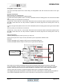
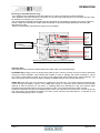
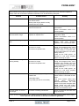
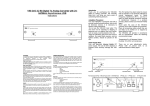
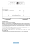
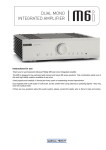
Instructions for use Thank you for purchasing the Musical Fidelity M1 PWR. The M1 PWR consists of a top quality Class-D switch-mode power amplifier circuit giving exceptional performance into virtually any speakers. It features efficient switching technology with zero crossover distortion artefacts and with just the right amount of feedback to give the best sound quality possible. It may also be used in a monoblock mode (with a matching amplifier for the other channel) in which the power output is considerably increased. It is complemented with a generous universal voltage power supply circuit, allowing astounding imaging, detail and transparency, to deliver all music types exactly as the artist originally intended. A line (loop) output allows for further or future expansion. The M1 PWR has been carefully designed to be partnered with M1 series, and also matches well with M3 and M6 series products. These combinations will yield one of the best high-fidelity systems available at any price. Used carefully, it should give many years of outstanding musical reproduction. Dust regularly with a soft duster or soft brush, but be careful when using cleaning or polishing agents - they may harm the surface finish. If there are any questions about the audio system, please consult the dealer who is there to help and advise. CONTENTS Section Page Safety Information – Mains plug (UK only), modification warning 3 General advice – Installation precautions 4 Disposal information – EU disposal information 5 Installation – Introduction, cleaning, installation, power connections, audio connections 6 Facilities and connections – Illustrations - main unit front & rear panels 7 Operation – Switching on 8 – Modes of operation – Setup (stereo mode) – Speaker connections – Input connections – Setup (mono mode) – Speaker connections – Input connections – Bi-wiring (mono mode) – Indicator LEDs – Standby LED – TEMP LED – Basic fault finding Problems? 9 10 11 Specifications 12 Manual history 13 Issue 2 Page 2 of 13 SAFETY INFORMATION IMPORTANT! (U.K. only) This unit is supplied in the U.K. with mains lead fitted with a moulded 13 amp plug. If, for any reason, it is necessary to remove the plug, please remove the fuse holder and dispose of the plug safely, out of reach of children. It must not be plugged into a mains outlet. The wires in the mains lead supplied with this appliance are coloured in accordance with the following code: Green and yellow .............................Earth Blue................................................ Neutral Brown ..................................................Live WARNING – This appliance MUST be earthed As the colours of the wires of the mains lead of this appliance may not correspond with the coloured markings identifying the terminals in the plug, proceed as follows: • The wire which is coloured green-and-yellow must be connected to the terminal in the plug which is marked with the letter E or coloured green or green-and-yellow, or by the earth symbol: • The wire which is coloured brown must be connected to the terminal which is marked with the letter L or coloured red. • The wire which is coloured blue must be connected to the terminal which is marked with the letter N or coloured black. • If connecting to a BS1363 plug, a 13 amp fuse must be used. WARNING: ANY MODIFICATIONS TO THIS PRODUCT NOT EXPRESSLY APPROVED BY MUSICAL FIDELITY WHO IS THE PARTY RESPONSIBLE FOR STANDARDS COMPLIANCE COULD VOID THE USER'S AUTHORITY TO OPERATE THIS EQUIPMENT. Issue 2 Page 3 of 13 GENERAL ADVICE Installation, Precautions & User Information This new M1 PWR is designed and built to provide trouble-free performance, but as with all electronic devices it is necessary to observe a few precautions: This unit features a BRIDGED speaker output and should NOT be grounded on either speaker output terminal as both red and black speaker terminals are effectively “hot”, i.e. carry signal. Please check if using any active “sub”, electrostatic, or other non standard potentially grounded speaker types directly connected to the speaker outputs of the M1 PWR. Consult speaker manual or supplier if in doubt. Heed all warnings shown on the back of the product. Only connect the M1 PWR to a mains outlet having the same voltage as marked at the back of the unit. Always ensure that when disconnecting and reconnecting your audio equipment the mains supply is switched off. Position the mains lead and signal interconnects where they are not likely to be walked on or trapped by items placed on them. Do not use near water, or place water-filled containers on the M1 PWR, for example, a flower vase or potted plants. If water does spill inside, immediately pull out the mains plug from the wall socket and inform the dealer, who should then check the unit before further use. Entry of liquid into the M1 PWR is dangerous, and may cause electric shock or fire hazard. Do not place the unit near direct heat sources such as radiators, direct sunlight or other equipment. Do not remove any covers or try to gain access to the inside. There are no user adjustments or fuses to change without qualification. Refer all service work to an authorised Musical Fidelity agent. * Note: Unauthorised opening of the equipment will invalidate any warranty claim. Dust regularly with a soft cloth or soft brush but be careful when using cleaning or polishing agents they may harm the surface finish. The electronics in modern hi-fi equipment is complex and may, therefore, be adversely affected or damaged by lightning. For protection of the audio system during electrical storms, remove the mains plugs. If after-sales service is required, to help the dealer identify the M1 PWR please quote the serial number located on the rear panel of the unit. Issue 2 Page 4 of 13 ITEM DISPOSAL INFORMATION DISPOSAL The crossed out wheeled bin label that appears on the back panel of the product indicates that the product must not be disposed of as normal household waste. To prevent possible harm to the environment please separate the product from other waste to ensure that it can be recycled in an environmentally safe manner. Please contact local government office or retailer for available collection facilities. DISPOSITION La poubelle sur roulettes barrées X, qui apparaît en logo sur le panneau arrière du produit, indique que celui-ci ne doit pas être traité comme un déchet domestique commun. Afin de protéger l'environnement, ce produit électronique devra être géré séparément et donc recyclé selon les nouvelles normes Européennes Rohs concernant les déchets d'appareils électroniques. Prière de contacter les services concernés gouvernementaux ou votre point de vente pour l'élimination et l'enlèvement de déchets électroniques équipés de composants électroniques. DISPOSAL La etiqueta cruzada hacia fuera del compartimiento que aparece en el panel trasero del producto indica que el producto no se debe reciclarse como basura normal de la casa. Para prevenir daños posible al ambiente separe por favor el producto de otras basura para asegurarse de que puede ser reciclada de una manera ambientalmente segura. Entre en contacto por favor a su oficina gubernamental local o a su minorista para las instalaciones disponibles de la colección. RIFIUTI L'etichetta del cassonetto barrato riportato sul retro dell'apparecchio indica che il prodotto non deve essere smaltito tramite la procedura normale di smaltimento dei rifiuti domestici. Per evitare eventuali danni all'ambiente, separare questo prodotto da altri rifiuti domestici in modo che possa venire riciclato in base alle procedure di rispetto ambientale. Per maggiori dettagli sulle aree di raccolta disponibili, contattate l'ufficio govenativo locale od il rivenditore del prodotto. FACHGERECHTE ENTSORGUNG: Das auf der Geräterückseite angebrachte Label deutet darauf hin, dass das Produkt nicht mit konventionellem Hauskehricht entsorgt werden darf. Um Schäden und Verschmutzungen an Umwelt und Mensch zu vermeiden, muss das Produkt fachgerecht entsorgt und von anderem Abfall getrennt werden. Wenden Sie sich bei Fragen hierzu an Ihren Fachhändler oder an eine öffentliche Informationsstelle. AFVAL Het label op de achterzijde van dit apparaat, een afvalbak op wielen met een kruis doorgehaald, geeft aan dat dit apparaat niet samen met gewoon huishoudafval mag worden weggegooid. Om mogelijke schade aan onze leefomgeving te voorkomen dient dit apparaat, gescheiden van gewoon huishoudelijk afval, te worden afgevoerd zodat het op een milieuvriendelijke manier kan worden gerecycled. Neem voor beschikbare inzamelplaatsen contact op met uw gemeentelijke reinigingsdienst of met uw elektronica leverancier. HÄVITTÄMINEN Yliruksattua jäteastiaa kuvaava tarra tuotteen takalevyssä kertoo, että tuotetta ei saa käsitellä normaalina talousjätteenä. Ympäristön suojelemiseksi on tuote pidettävä erillään muusta jätteestä ja se on kierrätettävä ekologisesti kestävällä tavalla. Ota yhteyttä laitteen myyjään tai Pirkanmaan Ympäristökeskukseen lähimmän kierrätyskeskuksen löytämiseksi. AFSKAFNING Logoet med en skraldespand med kryds over på bagsiden af apparatet indikerer at dette produkt ikke må kasseres som normal husholdningsaffald. For at forebygge mulig skade på miljøet, bedes De separere dette produkt fra andet affald, og sikre at det bliver genbrugt på en miljørigtig måde. Kontakt venligst de lokale myndigheder eller din forhandler for oplysning om nærmeste tilgængelige opsamlingssted for elektronikaffald. ΔΙΑΔΙΚΑΣΙΑ ΑΠΟΡΡΙΨΗΣ ΤΟ ΣΗΜΑ ΜΕ ΤΟΝ ΔΙΑΓΕΓΡΑΜΜΕΝΟ ΤΡΟΧΗΛΑΤΟ ΚΑΔΟ ΑΠΟΡΡΙΜΑΤΩΝ ΣΤΗΝ ΠΙΣΩ ΟΨΗ ΤΟΥ ΜΗΧΑΝΗΜΑΤΟΣ ΔΗΛΩΝΕΙ ΟΤΙ ΤΟ ΠΡΟΙΟΝ ΑΥΤΟ ΔΕΝ ΠΡΕΠΕΙ ΝΑ ΔΙΑΧΕΙΡΙΣΘΕΙ ΣΑΝ ΣΥΝΗΘΙΣΜΕΝΟ ΟΙΚΙΑΚΟ ΑΠΟΒΛΗΤΟ. ΠΡΟΣ ΑΠΟΦΥΓΗ ΕΝΔΕΧΟΜΕΝΗΣ ΕΠΙΒΑΡΥΝΣΗΣ ΤΟΥ ΠΕΡΙΒΑΛΛΟΝΤΟΣ, ΞΕΧΩΡΙΣΤΕ ΤΟ ΠΡΟΙΟΝ ΑΠΟ ΤΑ ΑΛΛΑ ΑΠΟΡΡΙΜΑΤΑ ΩΣΤΕ ΝΑ ΕΞΑΣΦΑΛΙΣΘΕΙ Η ΑΝΑΚΥΚΛΩΣΗ ΤΟΥ ΜΕ ΤΟΝ ΠΡΕΠΟΝΤΑ ΤΡΟΠΟ. ΠΑΡΑΚΑΛΟΥΜΕ ΝΑ ΕΠΙΚΟΙΝΩΝΗΣΕΤΕ ΜΕ ΤΗΝ ΤΟΠΙΚΗ ΥΠΗΡΕΣΙΑ ΑΝΑΚΥΚΛΩΣΗΣ Η ΜΕ ΤΟ ΚΑΤΑΣΤΗΜΑ ΑΓΟΡΑΣ ΓΙΑ ΠΕΡΙΣΣΟΤΕΡΕΣ ΛΕΠΤΟΜΕΡΕΙΕΣ. Issue 2 Page 5 of 13 INSTALLATION Introduction Congratulations on the purchase of the new M1 PWR. This unit will give top quality performance when used as a top quality power amplifier, delivering the best performance possible from any source. Cleaning Before cleaning the unit, switch off power at the mains switch and remove the mains plug from the wall socket. Clean the cabinet and remote control unit using a moist cloth. Using solvents, white spirit or thinners is not advised, as they could damage the surface finish. Installation Position the M1 PWR on a stable, horizontal surface where there is no risk of it being knocked, or subjected to vibration such as from loudspeakers. Important note: In normal operation, the unit dissipates a quantity of power at all times, and it is important that it is adequately ventilated. The M1 PWR must be protected from humidity – if the unit is moved from a cold place to a warm room, leave the unit for an hour or so to allow sufficient time for the moisture to evaporate. Please note: Musical Fidelity currently do not make any interconnecting cables, nor do we endorse any particular manufacturer’s cables. If necessary, please refer the dealer who can advise on quality cables for any particular setup. Power Connections The M1 PWR is supplied with a standard IEC mains cable which plugs into the IEC socket at the back of the unit. Output connections Binding post outputs: Use good quality speaker leads for absolute optimum sound quality. RCA loop outputs: Use good quality RCA phono audio cables (fully connected signal and ground), for optimum signal transfer. The LOOP OUT sockets pass on the INPUT signals totally unaffected. They are in fact directly connected to the INPUT RCA sockets to allow reconnection of further amplifiers/active subwoofers etc. Input connections LINE (RCA) input: Connect line level source to LINE input socket. Use good quality RCA phono audio cables (fully connected signal and ground) for optimum signal transfer. This input accepts LINE signals from any hi-fi volume-controlled source. It may be connected for example to the stereo outputs of an M1 CLiC (pre-outputs), or other pre-amplifier. Trigger connections Trigger input: Connect trigger output of controlling device to input socket. Use good quality 3.5mm jack cables (fully connected signal and ground) Unit accepts ±4 to ±15V DC trigger inputs. The M1 PWR can then be switched on or off by remote device(s) connected to its trigger input. Trigger output: Connect trigger input of controlling device to output socket. Use good quality 3.5mm jack cables (fully connected signal and ground). The M1 PWR then becomes the main controlling device and its power button will automatically switch on/off all devices thus connected to the trigger output. Issue 2 Page 6 of 13 FACILITIES & CONNECTIONS 1 2 3 4 5 1 POWER Blue power-on LED. 4 MONO Blue LED indicates MONO mode. 2 POWER/STBY button 5 3 STBY Orange standby LED TEMP Red LED indicates internal overheating. 6 7 11 12 8 9 10 13 6 TRIGGER IN 3.5mm jack socket 11 LINE INPUTS right and left 7 TRIGGER OUT 3.5mm jack socket 12 LOOP OUTPUTS right and left 8 STEREO/MONO mode switch 13 IEC MAINS INPUT 9 RIGHT speaker output binding posts 10 LEFT speaker output binding posts Issue 2 Page 7 of 13 OPERATION Switching on. When first connected to a mains supply the orange STDBY LED should light. This indicates the unit is in low power standby mode and that mains power is connected. (if it is not on, check mains wall socket switch is on, if present.) To turn the unit on, press the POWER STBY button once. The orange STBY LED should go out, and the blue POWER LED comes on. The M1 PWR is now fully switched on and ready to play music Modes of operation The unit features two modes of operation: STEREO mode allows the unit to be used as a standard stereo amplifier. For this mode the STEREO/MONO switch on the back panel should be in STEREO position, and MONO LED on the front panel will be out. MONO mode turns the unit into a more powerful monoblock. For a stereo system using M1 PWR in this way, two units will be required. For this mode the STEREO/MONO switch on the back panel should be in MONO position, and MONO LED on the front panel will be lit. The unit does not allow “HOT” or “LIVE” mode switching. This is to avoid potential speaker damage. The state of the switch is only read at switch-on (from standby). If change of mode is required it is necessary to switch the unit to standby first, change the switch and connection(s), then when the unit is switched on again the new mode will take effect as indicated by the MONO LED. Setup (Stereo mode) Speaker Connections Make sure the unit is switched OFF. Check the switch on back panel is in STEREO position. Connect the left hand speaker wires to the LEFT SPEAKER OUTPUT terminals/binding posts. Observe polarity of the cables and connections: Connect the + wire to red terminal, the – wire to black terminal. Ensure the same connection order is used at the speaker end of the cable. Check there are not stray strands of speaker wire and/or plugs that are causing short circuit by touching. Connect the right hand speaker wires to the RIGHT SPEAKER OUTPUT terminals/binding posts. Observe polarity of the cables and connections: Connect the + wire to red terminal, the – wire to black terminal. Ensure the same connection order is used at the speaker end of the cable. Check there are not stray strands of speaker wire and/or plugs that are causing short circuit by touching. Input Connections Connect left and right INPUTs to respective outputs of preamplifier or other preceding device.. RIGHT Speaker LEFT Speaker + - + - LEFT output Pre-amplifier RIGHT output Switch set to STEREO. Stereo mode audio leads connection diagram. (Trigger and mains leads omitted for clarity). Issue 2 Page 8 of 13 OPERATION Setup (Mono “block” mode) Two units, are hereby required for a stereo setup; one designated for the “left” channel; the other for the “right” channel. Speaker connections Make sure the unit is switched OFF. Check the switch on back panel is in MONO position. Connect the left hand speaker wires to the LEFT SPEAKER OUTPUT binding posts of the left hand M1 PWR unit. Observe polarity of the cables and connections: Connect the + wire to red, the – wire to black. Ensure the same connection order is used at the speaker end of the cable. Check there are not stray strands of speaker wire and/or plugs that are causing short circuit by touching. Connect the right hand speaker wires to the LEFT SPEAKER OUTPUT binding posts of the right hand M1 PWR unit. Observe polarity of the cables and connections: Connect the + wire to red, the – wire to black. Ensure the same connection order is used at the speaker end of the cable. Check there are not stray strands of speaker wire and/or plugs that are causing short circuit by touching. Input Connections Connect preamp outputs to LEFT inputs only on each unit. Please note only the LEFT input is active, the RIGHT input is inoperative in MONO mode. Example: Connect preamplifier LEFT output to LEFT input on left hand M1 PWR unit. Connect preamplifier RIGHT output to LEFT input on right hand M1 PWR unit. LEFT Speaker + LEFT output Pre-amplifier RIGHT output Switches set to MONO. RIGHT Speaker + - Mono (block) mode audio leads connection diagram. (Trigger and mains leads omitted for clarity). Note: When unit is switched to MONO mode the LEFT and RIGHT RED speaker terminals are internally connected together. Similarly, the LEFT and RIGHT BLACK speaker terminals are also internally connected together. Thus the power from the two internal amplifiers is combined to form a more powerful monoblock. Only the LEFT input, however, accepts the signals, RIGHT input is inoperative in MONO mode. The diagram above shows the speakers connected to the LEFT hand outputs. It is also perfectly acceptable to use the RIGHT SPEAKER outputs as in mono mode they are exactly the same connection internally. Issue 2 Page 9 of 13 OPERATION Bi-wiring (in monoblock mode only) It is possible to take advantage of the above feature to “bi-wire” the outputs to suitable speakers. Such speakers must have at least four terminals; two for the treble, high frequency (or HF) driver and two more for the bass, low frequency (or LF) driver. Any “shorting links” between treble and bass input terminals (on the speakers) must be removed for maximum benefit. These links normally are visible under the speaker’s terminals as gold plates/bars connecting the terminals up in pairs. Please consult speaker manuals/user support for more details. LEFT Speaker + HF - HF LEFT output Pre-amplifier RIGHT output + LF - LF Switches set to MONO. RIGHT Speaker + HF - HF + LF - LF Mono (block) mode “bi-wiring” audio leads connection diagram. (Trigger and mains leads omitted for clarity). Indicator LEDs There are two further indicator LEDs that allow the state of the unit to be determined. STANDBY LED (orange) comes on briefly during start-up this is normal. It is also common to see the LED flash during loud music passages. This indicates the amplifier is close to clipping and further increases in volume may cause sound quality to suffer as a result. If the clipping light often flashes during normal listening, turn down the volume and/or consider using the amplifier in MONO mode for more power (see above). TEMP LED (red) will come on if the device is getting too hot internally. This could indicate excessively high current through the speaker outputs. If the TEMP LED comes on, maximum power output will be internally reduced to allow the device to cool down. A Flashing RED LED indicates the chip has reached upper temperature limit and although the unit may continue to work, it should be shut down to clear the fault. Continuous operation into very low impedance/short circuit may cause the unit to shut down. Switch off the unit and check wiring and speakers themselves for short circuits. Allow the M1 PWR approx. 10 minutes to cool down before attempting to turn it on again. Issue 2 Page 10 of 13 PROBLEMS? Basic problem-solving with an amplifier is similar to troubleshooting other electrical or electronic equipment. Always check the most obvious possible causes first, such as the following examples: Problem Probable Cause Remedy No power Mains power supply is not fully inserted into mains socket Mains power supply lead is not fully inserted into rear socket Plug in securely No sound Wrong connections between input sources and the unit. Check audio input lead connections Check mono/stereo switch is in correct position. Sound is not precise, lacking in bass and stereo image Speaker wiring wrong way round at speaker or amplifier end Check wiring polarity at both ends of speaker cables Check mono/stereo switch is in correct position. Intermittent Flashing Orange LED Clipping is about to occur Normal at higher listening levels and/or with less sensitive speakers. Turn volume down a bit. RED LED lit or flashing Unit has overheated Overload on output Excessive temperature rise Switch off and check speaker wiring. If this happens often, check speakers and consider using unit in mono mode (in conjunction with a second M1 PWR unit, in a stereo setup). See P.8 Allow the M1 PWR approx. 10 minutes to cool down properly before switching on again. RED LED lit and Orange LED flashing steadily Unit has cut out. Overload on output Excessive temperature rise Switch off and check speaker wiring. If this happens often, check speakers and consider using unit in mono mode (in conjunction with a second M1 PWR unit, in a stereo setup). See P.8 Allow the M1 PWR approx. 30 minutes to cool down properly before switching on again. Hum Audio connector plug not fully pushed in Cable Fault Unsuitable Cable (e.g. cable grounds not connected) Insert plug securely Check cable is connected at both ends. N.B. some esoteric cables have internal wiring intentionally disconnected/modified. For best results on all inputs analogue AND digital, please use good quality screened coax; signal and screen directly connected both ends. No audio output, or too low level output Incorrect or missing connections Check connections and make sure they are secure. If none of these actions affect a cure, please contact the dealer, or an authorised Musical Fidelity service agent. Never open the case of the unit, as this will invalidate the guarantee. Issue 2 Page 11 of 13 SPECIFICATIONS Output Stereo mode Mono mode Output Power 65W 130W 100W 200W into 8Ω into 4Ω Total harmonic distortion Frequency response Crosstalk Signal to noise <0.03% <0.5dB 85dB >94dB <0.02% <0.5dB [n/a] >100dB 20Hz to 20kHz 20Hz to 20kHz “A”- wtd Connections Line level input Line level outputs 1 pair RCA line in left and right 1 pair RCA line out left and right Speaker outputs 2 pairs binding posts Trigger input Trigger output 3.5mm (⅛”) mono jack ±4.5 to ±15V DC 3.5mm (⅛”) mono jack +12V DC Power requirement Mains voltages 90-250VAC 50/60Hz Consumption 350 Watts maximum Weight Unit only, unboxed 3.9 kg In shipping carton & inc. accessories 4.6 kg (8⅔ lbs) (10⅛ lbs) Dimensions Wide High, including feet Deep, including terminals 220 mm 100 mm 315 mm (8⅔”) (4”) (12½”) Standard accessories IEC type mains lead (10-Amp type) Musical Fidelity reserves the right to make improvements which may result in specification or feature changes without notice. E&OE. Issue 2 Page 12 of 13 MANUAL HISTORY RELEASE DATE CHANGES th 2011 Issue 1 Dec 14 Issue 2 22nd February 2012 Issue 2 1st issue. Fault LEDs clarified Page 13 of 13