1
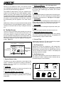
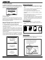
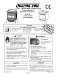
R
User’s Manual
WALL CONTROL
Tested and
Listed by
Portland
Oregon USA
O-T L
C
US
OMNI-Test Laboratories, Inc.
Part SRV7000-451
Mt. Vernon Pellet Appliances (AE)
EDGE™ 60 Pellet Fireplace
NOTICE
DO NOT DISCARD THIS MANUAL
• Read, understand and • Leave this manual with
follow these instructions for safe installation and operation.
party responsible for use
and operation.
T
O
N RD
O A
D SC
I
D
• Important operating and
maintenance instructions included.
CONTACT INFORMATION:
CAUTION
Check building codes prior to installation.
• Installation MUST comply with local, regional, state and
national codes and regulations.
• Consult local building, fire officials or authorities having
jurisdiction about restrictions, installation inspection, and
permits.
Hearth & Home Technologies
1445 North Highway, Colville, WA 99114
Division of HNI INDUSTRIES
Please contact your Quadra-Fire dealer with any questions or
concerns. For the number of your nearest Quadra-Fire dealer log
on to www.quadrafire.com
TABLE OF CONTENTS
A. Introduction....................................................2
D. Main Menu
B. Main Screen
1,. System Status Codes..........................2
2.
3.
4.
5.
6.
Current Time........................................2
Set Temperature..................................2
Notification Icons..................................2
Function Buttons..................................3
Current Temperature...........................3
C. General Information about using the
Wall Control......................................................3
1.
2.
3.
4.
5.
6.
Set Comfort Level (Temperature)........3
Auto/Manual/Off...................................4
Fuel Type.............................................4
Programming.......................................5
Set Day/Time.......................................4
User Settings.......................................6-7
E. Quick Start Guide.............................................8-9
F. Service Information..........................................10
G. Error Codes......................................................10
H. Battery Back-up (Optional).............................10
I. Troubleshooting Guide.....................................11
www.quadrafire.com
7014-101F
April 1, 2009
R
A. Introduction
c. AUTO: (x) or MAN: (x) (x) = heat output level
Welcome to the Quadra-Fire family. This manual will help
you understand and operate the wall control attached to
your new pellet Advanced Energy appliance.
Indicates both the operating cycle (automatic or manual)
and the current heat output level. The heat output level will
be “H” high, “MH” medium high, “M” medium, “ML” medium
low and “L” low.
The Quadra-Fire Wall Control is not just a traditional thermostat, but an integral part of the pellet appliance system.
While it has many of the features one would expect from
an advanced thermostat, including programmable setback
capabilities and current temperature display, it also indicates
the system’s current operating cycle and state. It does this
by communicating with the appliance via a wired connection.
Indicates that the system is turned on and is functioning normally, but there is no call for heat (the room temperature is
not below the set temperature). See Figure 7.1 on page 7.
Additionally, it allows you to set parameters that will optimize
the performance of your pellet appliance system. These parameters are accessed with an easy to navigate menu system.
f. AUTO-CLEAN
d. READY
e. SHUTDOWN
Indicates the system is shutting down, either because it is no
longer calling for heat or the maximum burn time has been
reached and the system must run an auto-clean cycle.
Indicates the system is running the firepot auto-clean cycle.
g. OFF
B. The Main Screen
The key to being comfortable while operating your new wall
control is to familiarize yourself with the main screen. The
main screen shows, at a glance, the status of the system,
the most important settings and the current temperature. Additionally, the main screen indicates with simple icons many
user actions required to keep your appliance working as intended. Figure 2.1.
Indicates the system has been shut down by the user.
h. MAINT BURN (Battery Back-up Only)
The maintenance burn is to keep the system from shutting
down when operating on battery backup. The appliance will
not automatically re-light in manual mode.
2. Current Time
Indicates the current time. The time is used for the programmable setback features of the wall control.
System Status
Current Time
3. Set Temperature
READY
Current
Temperature
73
MENU
12:30 PM
Set at: 73
HEAT OUTPUT
Current Set
Temperature
Notifications
Icons
Indicates the current set temperature. It will change automatically as the control progresses through the 7 day setback program. If the wall control is in HOLD TEMP cycle the
“Set at:” indication will change to “Hold at:” and displays the
operating temperature setting.
4. Notification Icons
Function Labels for the Function Buttons
The system notification area uses icons to indicate if an action needs to be taken. In battery mode it indicates the approximate charge level of the battery.
Figure 2.1
1. System Status Codes
The status area is used to indicate the current status of the
system. It indicates if the system is running in automatic or
manual cycle, if it is turned on or off and where it is in the
operating sequence.
a. START-UP
Indicates that the appliance is in start-up cycle and is in the
process of lighting an initial charge of fuel.
Hopper Lid Open
Low Fuel
Operating on Optional Battery Backup
b. SS-LOW or SS-MED (SS = soft start)
Indicates the soft-start portion of the lighting sequence. In
these stages the fire begins to gradually build to operating temperature.
Door Open
Fully Charged
2/3 Charge
1/3 Charge
No Charge
Figure 2.2
Page 7014-101F
April 1, 2009
R
5. Function Buttons
1. Set Comfort Level (Temperature)
The function buttons have two labels above them in the display area. Their labels can change depending on the menu
screen. On the main screen the left button will bring up the
system menu and the right button has functionality only in
MANUAL cycle. Figure 3.2.
The most basic operation of the wall control is to turn the
appliance on or off depending on the requirement for heat.
From the main screen, the SET COMFORT LEVEL screen
can be activated by pressing the UP or DOWN button on the
right side of the display area. 6. Current Temperature
The first time either button is pressed the display changes to
the SET COMFORT LEVEL screen and shows the current
set temperature. Subsequent presses or holding the UP or
DOWN button will change the set temperature. Figure 3.2.
The current temperature area indicates the temperature of
the room where the wall control is located. The temperature displayed can be in units of Fahrenheit or Celsius. The
desired units can be selected via the system menu. See
Figure 6.5 on page 6.
C. General Information About Using the Wall
Control
When a button is pressed and the screen changes from the
main screen to one of the other screens, the backlight will illuminate the display area. As buttons are pressed, the backlight continues to be illuminated.
Most screens have a DONE button which can be used to
return to the previous screen ultimately returning to the main
screen.
The wall control will automatically revert back to the starting
screen if there is no activity for 15 seconds except for the
COMFIRM FUEL CHANGE screen. The main screen will be
illuminated for an additional 10 seconds and the backlight
will shut off.
If the wall control is subjected to a static shock, the screen
may go blank. If this happens, wait 25 seconds and press
any button. This will reset the screen restore functionality
and turn on the back light. If this does not work, call your
dealer.
You can override the programming either permanently or
temporarily. The HOLD TEMP button (lower right) on the
SET COMFORT LEVEL screen is used to override preset
programming. Figure 3.3. By pressing the HOLD TEMP
button, the current set temperature will permanently override
any programmed temperature in the 7 day setback programming. This is a convenient way of overriding a program when
your schedule changes temporarily and you don’t want to
reprogram the setback functions on the wall control.
To release the permanent override, press the button labeled
RESUME when in the HOLD TEMP cycle. Pressing the button again will resume the programming at the next program
interval. Figure 3.4.
To temporarily override the programming, use the UP and
DOWN buttons only and do not press the HOLD TEMP button. The display will show how long the new temperature will
hold before it returns to the next scheduled programming. Figure 3.3.
D. The Main Menu
Buttons
Up
Down
Function Buttons
The menu is the heart of customizing the operation of the
pellet appliance system to your personal liking. The choices
on this menu are:
Figure 3.2
MENU
Set Comfort Level
Auto/Manual/Off
Fuel Type
User Settings
Figure 3.3
MENU
Program
Set Day/Time
Set Date
Service Info
COMFORT LEVEL
70.5 F
ON HOLD
DONE
Figure 3.1
April 1, 2009
RESUME
Figure 3.4
7014-101F
Page R
3. Fuel Type
2. Auto / Manual / Off Selection
a. Automatic
In the AUTOMATIC cycle the wall control will turn the appliance on and off automatically and also turns the heat output
level up or down depending on the temperature setting. The
further away the room temperature is from the set temperature, the higher the heat output.
AUTO/MANUAL SETTINGS
Automatic
Manual
Off
The FUEL TYPE screen is used to select the fuel that will be
used with the pellet system. The list on this screen indicates
all fuel choices available to burn in the appliance.
NOTE: The list of fuels can be updated by your local
dealer as they become available.
To select a fuel type, use the UP/DOWN buttons to scroll to
the desired fuel type and then press the button under “Select”. The arrow will change to indicate the currently selected fuel.
NOTE: If you are burning a high ash fuel set the fuel selection to “Utility Pellets”.
When purchasing corn or wheat to burn in your appliance,
read the ingredient label very carefully. Do NOT purchase
fuel that contains any additives such as oils (i.e. soybean
oil) and meals as it will result in poor appliance performance. Figure 4.1
b. Manual
In MANUAL cycle, the heat output remains the same regardless of the difference between the set and room temperatures. The wall control will function as a simple on/off
thermostat. When the system is set to MANUAL the HEAT
OUTPUT selection is added in the lower right corner. If you are buying corn or wheat the only ingredient that should
be listed is corn or wheat.
FUEL SELECTION
Corn
UtilityPellet
SoftwoodPellet
SunflowerSeeds
Wheat
HardwoodPellet
Press the button under this selection to access this feature. The HEAT OUTPUT screen is used to set the level of heat
produced whenever the wall control calls for heat. Figure
4.3. The HEAT OUTPUT screen is not accessible in AUTOMATIC cycle.
AUTO/MANUAL SETTINGS
Automatic
Manual
Off
SELECT
Figure 4.5
4. Program (7 Day Programming)
The wall control is pre-programmed at 68oF for all time settings. It will remain there until it is re-programmed.
Figure 4.2
The wall control can be programmed as a setback thermostat. Each day of the week has four program periods. The
wall control menus have some features that make it easy to
program groups of days alike. This minimizes the number
of steps required to program the wall control for most applications.
Medium
c. OFF
DONE
Figure 4.3
This selection turns the appliance off. When the appliance
is set to OFF, it will not light regardless of room temperature. Use this setting when cleaning and maintaining your appliance.
To access the programming screen, select Program from
the menu screen and then select the desired programming
range from the PROGRAMMING RANGE screen.
AUTO/MANUAL SETTINGS
Automatic
Manual
Off
PROGRAMMING RANGE
Full Week
Mon-Fri
Sat-Sun
Monday
Figure 4.6
Figure 4.4
Page 7014-101F
April 1, 2009
R
a. Full Week
5. Set Day/time
NOTE: It is important to note that the most recent programming entry will override all previous programming for an individual day or range of days.
The small triangle on the left side indicates the current active
programming line. Figure 4.6 on page 4. For each of the
four intervals available to program there are three adjustable
values: set hour, set minutes and set temperature. You will
need to increase or decrease the hour to change from AM
to PM.
When the screen is first entered the “Wake Hour” is highlighted. Use the UP/DOWN buttons to adjust the hour to
the desired hour and press the button under “Set/Next”. The
highlight will move to the minutes display. Adjust the minutes and press “Set/Next.” The highlight is now on the temperature value. Set the desired temperature for the Wake
period and press “Set/Next.”
a. Set Day/Time
In order for the setback function to work properly the wall
control must be aware of the current time. The SET DAY/
TIME screen is used to set the system clock. When the
screen is entered the day of the week is highlighted.
Use the UP/DOWN buttons to change this to the current
day of the week. Press the button under “Set/Next” and the
highlight will be moved to the current hour field. Again, use
the UP/DOWN buttons to set this to the current hour. Press
the “Set/Next” button again and the current minute display is
highlighted.
Use the UP/DOWN buttons to adjust to the correct minutes
and press “Set/Next” one last time. The highlight will move
back to the original day of week display.
The highlight is now on the hour display for the Day period,
and the triangle has moved to the second line. Continue
programming each value as desired. (To store the final value
be sure to press “Set/Next” to return the highlight to the first
value on the screen.)
When you are finished making changes, or if you just entered the programming screen to view the set program,
press “Done” or let the display return to the main screen
automatically.
PROGRAM: Full Week
68 F
68o F
68o F
68o F
DONE
SET/NEXT
DONE
10 47
SET/NEXT
Figure 5.4
Wednesday
o
Wake: 6:30 AM
Day: 7:59 AM
Evening: 4:00 PM
Night: 11:00 PM
Wednesday
10 47
Figure 5.5
Figure 5.1
Wednesday
PROGRAM: Full Week
o
Wake: 6:30 AM
Day: 7:59 AM
Evening: 4:00 PM
Night: 11:00 PM
68 F
68o F
68o F
68o F
DONE
SET/NEXT
10 47
Figure 5.6
Figure 5.2
PROGRAM: Full Week
o
Wake: 6:30 AM
Day: 7:59 AM
Evening: 4:00 PM
Night: 11:00 PM
68 F
68o F
68o F
68o F
DONE
SET/NEXT
Figure 5.3
April 1, 2009
7014-101F
Page R
b. Set Date
When the SET DATE screen is entered the month name is
highlighted. Use the UP/DOWN buttons to select the proper
month then press the button under “Set/Next.”
6. User Settings
Items that are rarely changed are stored under the USER
SETTINGS.
The highlight will move to the day of the month display. Using
the UP/DOWN buttons, select the current date then press
“Set/Next.” The highlight will move to the year display. Select
the current year and press “Set/Next” then the highlight will
be back on the month name display.
September
USER SETTINGS
Temp Units F/C
Flame Height Adjust
Temp Differential
USER SETTINGS
Temp Cal
Properties
Elevations
Conv Blower Speed
2007
Figure 6.1
Figure 6.4
a. Temp Units F/C
September
28
2007
The TEMP UNITS screen is used to change from Fahrenheit to Celsius and back for the temperatures displayed.
Figure 6.2
Figure 6.5
September
28
Figure 6.3
b. Flame Height Adjust
2007
The FLAME HEIGHT ADJUST screen is used to adjust the
flame height (fuel feed rate) for specific installation and fuel
type. The dealer will usually adjust this if necessary on installation and can advise on specific settings for a particular application.
Figure 6.6
Page 7014-101F
April 1, 2009
R
c. Temp Differential
f. Elevation
The TEMPERATURE DIFFERENTIAL screen is used to
change the set default temperature differential. This sets
how far below the set point the wall control allows the room
temperature to fall before the appliance turns back on. It is
usually set at time of installation.
The ELEVATION screen allows you to adjust the appliance
to your specific elevation. Press the UP/DOWN buttons
to select your elevation. The message in the center will
change between NORMAL and HIGH. If you select HIGH,
it will replace the normal fuel tables with specific high fuel
tables. You MUST select a fuel type after selecting HIGH.
Please note that changing the elevation will delete any
custom or new fuel table loaded into the appliance. You
must confirm your choice on the CONFIRM ELEVATION
CHANGE screen. This allows you to reverse your decision
if necessary. Figure 7.5.
ELEVATION
Over 4000 FT
Normal / High
Figure 7.1
d. Temperature Calibration
Up to 4000 FT
The TEMPERATURE CAL screen is used to calibrate the
temperature on the wall control. If for some reason you feel
the wall control is not accurately reading the temperature
you can calibrate it to a thermostat that you know is accurate. Press the UP/DOWN buttons to the desired temperature.
DONE
Figure 7.4
CONFIRM ELEVATION CHANGE
Changing elevations will
delete any custom or
new fuel tables loaded into
the stove.
Are you sure?
TEMPERATURE CAL
71.6
DONE
OF
Cal Adj:
YES
NO
-13
SET
Figure 7.5
Figure 7.2
g. Convection Blower Speed
e. Properties
The PROPERTIES screen shows the version of software for
the control board and wall control. If you are placing a service
call with your dealer, they may ask you to go to this screen
and read them the information under “WC” and “SC”.
The CONV BLOWER SPEED screen allows you to adjust the blower speed to your individual preference. Press
the UP/DOWN buttons to select your blower speed. The
message in the center will change between NORMAL and
QUIET.
NORMAL allows the convection blower to reach maximum
RPM at 135 degrees and QUIET at 165 degrees.
PROPERTIES
UFTI: 029
WC 40h
SC 6Bh
Rev: 004
CB 000
TC:
-28
CV 000
DONE
CONV BLOWER SPEED
Normal
Normal / Quiet
Quiet
DONE
Figure 7.3
Figure 7.6
April 1, 2009
7014-101F
Page R
E. Quick Start Guide
NOTICE: Any button pressed will turn on the backlight. The wall control will auto-
matically revert back to the starting screen if there is no activity for 15 seconds;
except for the “CONFIRM FUEL CHANGE” screen.
.
Choosing Fuel Type
Buttons
Room
Temp
READY
12:30 PM
73
Set at: 73
MENU
Up
Down
HEAT OUTPUT
READY
12:30 PM
71
Set at: 68
MENU
Function Buttons
Wall Control for Reference
Turning on appliance
READY
12:30 PM
71
Set at: 68
1. At the starting screen, press “MENU”
button once or twice until “MENU”
screen appears.
MENU
Set Comfort Level
Auto/Manual/Off
Fuel Type
FUEL SELECTION
Set Comfort Level
Auto/Manual/Off
Fuel Type
Softwood Pellet
Sunflower Seeds
Wheat
Hardwood Pellet
AUTO/MANUAL SETTINGS
Automatic
Manual
Off
3. Highlight “MANUAL”. Press “SELECT”.
4. Press “DONE” twice or wait 15 seconds for starting screen to re-appear.
Page 71
Set at: 68
MENU
1. At the starting screen, press “MENU”
button once or twice until “MENU”
screen appears.
Fuel Type
User Settings
2. Highlight “USER SETTINGS” using the
“UP/DOWN” buttons to the right side of
the display. Press “SELECT”.
USER SETTINGS
User Settings
2. Highlight “AUTO/MANUAL/OFF”. Press “SELECT”.
12:30 PM
Set Comfort Level
Auto/Manual/Off
1. At the starting screen, press “MENU”.
MENU
READY
MENU
User Settings
2. Highlight “FUEL TYPE” using the “UP/
DOWN” buttons to the right side of the
display. Press “SELECT”.
MENU
Choosing TEMP UNIT:
°f or °c
3. Scroll down and highlight “HARDWOOD PELLET” or your fuel type. 4. Now press “SELECT” to choose new
fuel.
Temp Units F/C
Flame Height Adjust
Temp Differential
3. Highlight “TEMP UNITS F/C” using the
“UP/DOWN” buttons to the right side of
the display. Press “SELECT”.
CONFIRM FUEL CHANGE
Please empty hopper
of old fuel type and
ensure firebox is clean.
Please refer to
section 8 in manual.
DONE
5. Press “DONE”
change.
to
confirm
fuel
6. Press “DONE” twice or wait 15 seconds for starting screen to re-appear.
7. Fill the hopper with fuel. If the hopper was completely empty or has run
out of fuel, put approximately 1/2 cup
of pellets into the firepot for a quick
restart.
8. Be sure the hopper lid and glass
door are both closed.
7014-101F
4. Press the “UP” or “DOWN” button
to set desired temperature unit and
press “SELECT”..
5. Press “DONE” twice , or wait 15 seconds for starting screen to re-appear.
April 1, 2009
R
E. Quick Start Guide (Cont’d)
Setting Comfort Level
READY
12:30 PM
READY
12:30 PM
71
Set at: 68
71
Set at: 74
Hold
MENU
HEAT OUTPUT
1. Press and hold “UP” or “DOWN” button to set desired temperature.
NOTE:
Setting Heat Output
Set temperature must be 3
degrees higher than room
temperature for appliance to
start.
74 ºF
2. Press “HOLD TEMP”.
MENU
ERROR LIST
Min Firepot Temp
HEAT OUTPUT
1. At the starting screen, press “HEAT
OUTPUT”.
Medium High
2. Use the “UP” button to change “HEAT
OUTPUT LEVEL” to ”MEDIUM-HIGH”.
3. Press “DONE” twice or wait 15 seconds for starting screen to re-appear.
RETRY
74
2. Fill the hopper with fuel and press
the “RETRY” button twice. The first
time turns on the back light, the second time starts the retry function.
SHUTDOWN
MENU
ON HOLD
RESUME
SERVICE
1. If the appliance has stopped operating, check the wall control screen. If
it is showing “Min Firepot Temp” the
hopper has run out of fuel.
71
SET COMFORT LEVEL
ºF
DONE
HOPPER OUT OF FUEL
12:30 PM
Set at: 74
Hold
HEAT OUTPUT
3. If the wall control screen changes to
a “SHUTDOWN” screen that means
your appliance has not completed the
full shutdown cycle. Depending on
where it was in the cycle it can take
from one to ten minutes to restart.
3. Press “DONE”.
When the shutdown cycle is complete
the wall control screen will display
“STARTUP”. Continue to Step 4.
STARTUP
71
MENU
12:30 PM
Set at: 74
Hold
HEAT OUTPUT
4. If the wall control screen changes to a “STARTUP” screen after pressing
“RETRY” that means your appliance
has already completed the shutdown
cycle. You must wait until the wall
control screen displays the startup
screen and then put 1/2 cup of pellets in the firepot for a quick restart.
5. Be sure the hopper lid and glass door
are both closed.
April 1, 2009
7014-101F
Page R
F. Service Information
The SERVICE INFORMATION screen displays contact information for Hearth & Home Technologies Customer Service Line. The local dealer may have changed this upon or
before the installation to indicate a dealer hot line.
www.quadrafire.com
to locate your nearest
dealer
DONE
Operating on Battery Back-Up
• A battery icon appears on your wall control to let you
know you are now operating on battery power. Figure
10.3.
• The fire must be manually lit as the appliance will no
longer automatically light. See page 4.
• Use only approved fire starting gel to start the fire.
• The high burn rate is no longer available on battery
back-up.
ERROR LIST
• Each level drops down one level, i.e the high burn becomes medium-high burn and so on.
Figure 10.1
G. Error Codes
If a system error occurs that forces the system to stop operating an error screen appears. Depending upon the error
type, up to three retry attempts are allowed after which a
service professional is required. • If the battery charge falls below 10 volt it can no longer
sustain the appliance operation and the appliance will
shut down. You must disconnect and reconnect the battery to start it up again.
Recommended Battery
• 12 volt deep cycle battery, (i.e., marine or RV type). Press the ERROR LIST button to display the latest error. • A 12 volt battery cable is available through your local
Figure 10.1. See page 11 for a list of error codes.
dealer.
H. Battery Back-up System (Optional)
The appliance has been designed to operate on an optional
battery back-up system. If you have frequent power outages in your region, hook
the appliance up to a 12 volt battery and it will automatically
switch to battery power in the event of a power failure. The
12 volt power cord sold as a separate accessory does not
charge the battery. Refer to the Owner’s Manual for your appliance for instructions
on how to attach the cable to your appliance. The following
are the screens you will see when using a back-up battery.
MANUAL LIGHT PROCEDURE
Press “CONTINUE”
button to start manual
lighting sequence
Current Tem: 72O F
13 Volts
12 Volts
11 Volts
Battery
Below
10 Volts
Figure 10.3
Wall Control Display
The wall control will display the battery icon when operating
in the battery back-up mode. Figure 10.4.
“Maint Burn” will display when
the thermostat has reached the
set room temperature and will
run on low until it reaches its
auto-clean clycle time.
CONTINUE
MANUAL LIGHT PROCEDURE
Please wait while
feed charge is loading
into firepot
MANUAL LIGHT PROCEDURE
Open door...
Manually light fuel...
Close door
MAINT BURN
12:30 PM
73
Set at: 73
MENU
HEAT OUTPUT
Battery icon.
Figure 10.2
Page 10
Figure 10.4
7014-101F
April 1, 2009
R
I. TROUBLESHOOTING
With proper installation, operation, and maintenance your appliance will provide years of trouble-free service. If you do experience a problem, this troubleshooting guide will assist a qualified service person in the diagnosis of a problem and the corrective action to be taken.
NOTE: This troubleshooting guide should only be used by a qualified service technician.
Possible Cause
Error Message
Corrective Action
Bad wall control or control board
3 wires have loose connections or installed
wrong
Replace wall control or control board
Check connections
Drop tube thermocouple is broken or leads
are reversed
Check connections
Check connections
TC = Thermocouple
Firepot thermocouple is broken or leads
are reversed
SNAP DISC TRIPPED
Overheat sensor (snap disc) has tripped
If have power switch, turn off, manually reset
the snap disc & turn power back on. If no
power switch, unplug appliance
Convection blower may need cleaning
Clean convection blower if needed.
VACUUM SW ERROR
Vacuum switch is bad
Check connections. By-pass vacuum with
jumper wire, if run, switch is bad. Replace
switch.
Vacuum hose is plugged/disconnected
Check vacuum hose
Combustion blower is blocked/jammed
Remove blockage
BAD TC DROP TUBE
TC = Thermocouple
BAD TC FIREPOT
SW = Switch
COMB BLOWER JAMMED
Replace thermocouple
Replace thermocouple
Replace blower if necessary
If have power switch, turn off & turn back on to
clear error. If not unplug the appliance.
AUGER JAMMED
Auger jammed, feed motor bad
Pull the feed system and inspect
MISSED IGNITION
Igniter bad or poor harness connection
Check connections, if OK replace igniter
Out of fuel or fuel is bridging in hopper
Break up bridging pellets. Refill hopper
Faulty firepot thermocouple, connection is
shorted
Replace the thermocouple & press Retry
Out of fuel
Refill hopper
Clear jam and then press Retry button
MIN FIREPOT TEMP
Add handful of pellets to the firepot to prime it
Press the Retry button
MAX DROP TUBE TEMP
CONV BLOWER JAMMED
Stove in over-heat condition
Wrong fuel table setting Confirm setting matches burning fuel
Flame height set too high
Adjust flame height
Components may need cleaning
Clean the firebox, heat exchanger, convection
blower, firepot and ash pan
Convection blower blocked/jammed
Remove blockage
Replace blower if necessary
If have power switch, turn off & turn back on to
clear error. If not unplug the appliance.
CHECK ASHPAN
SCREEN GOES BLANK
Auto-clean jammed
If ash pan is empty, check for a jam. Use a
screw driver and firmly push in the firepot floor
holes and flex spring and push toward home
to release jam.
Auto-clean switch is bad
Replace switch
Linkage has become disconnected
Reconnect linkage.
Static discharge or nearby lightening or
If have power switch, turn off & turn back on to
refresh the screen. If not unplug the appliance.
Electric Fast Transients at the input mains
Hopper lid not closed all the way
Switch is out of adjustment (auger will not
function)
April 1, 2009
Close the lid. If that didn’t work replae the
switch
Adjust or replace switch
Firebox door is not latched properly
Adjust or replace door switch
Fireplace not rolled in completely
Adjust or replace interlock switch
Out of fuel
Check the latch, if OK, replace switch
7014-101F
Page 11
R
CONTACT INFORMATION:
Hearth & Home Technologies
1445 North Highway
Colville, WA 99114
Division of HNI INDUSTRIES
Please contact your Quadra-Fire dealer with any questions or concerns.
For the number of your nearest Quadra-Fire dealer
visit our web site at www.quadrafire.com
NOTICE
• Leave this manual with
party responsible for use
and operation.
T
O
N RD
O A
D SC
I
D
DO NOT DISCARD THIS MANUAL
• Important operating and • Read, understand and
follow these instrucmaintenance instructions for safe installations included.
tion and operation.
We recommend that you record the following pertinent
information for your appliance.
Date purchased/installed: Serial Number: Location on appliance: Dealership purchased from: Dealer phone: Notes: This product may be covered by one or more of the following patents: (United States) 4593510, 4686807, 4766876, 4793322, 4811534,
5000162, 5016609, 5076254, 5113843, 5191877, 5218953, 5263471, 5328356, 5341794, 5347983, 5429495, 5452708, 5542407,
5601073, 5613487, 5647340, 5688568, 5762062, 5775408, 5890485, 5931661, 5941237, 5947112, 5996575, 6006743, 6019099,
6048195, 6053165, 6145502, 6170481, 6237588, 6296474, 6374822, 6413079, 6439226, 6484712, 6543698, 6550687, 6601579,
6672860, 6688302B2, 6715724B2, 6729551, 6736133, 6748940, 6748942, 6769426, 6774802, 6796302, 6840261, 6848441,
6863064, 6866205, 6869278, 6875012, 6880275, 6908039, 6919884, D320652, D445174, D462436; (Canada) 1297749, 2195264,
2225408, 2313972; (Australia) 780250, 780403, 1418504 or other U.S. and foreign patents pending.
Page 12
7014-101F
April 1, 2009