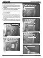
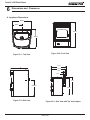
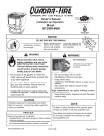
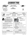
1
R
SANTA FE PELLET STOVE
Owner’s Manual
Installation and Operation
Model:
SANTAFE-NZ-MBK
CAUTION
DO NOT DISCARD THIS MANUAL
• Important operating and • Read, understand and
follow these instrucmaintenance instructions for safe installations included.
tion and operation.
WARNING
party responsible for use
and operation.
WARNING
Please read this entire manual
before installation and use of this
pellet fuel-burning room heater.
Failure to follow these instructions
could result in property damage,
bodily injury or even death.
• Do not store or use gasoline or other flam-
mable vapors and liquids in the vicinity of this
or any other appliance.
• Do not overfire - If any external part starts to
glow, you are overfiring. Reduce feed rate. Overfiring will void your warranty.
• Comply with all minimum clearances to combustibles as specified. Failure to comply may
cause house fire.
HOT SURFACES!
Glass and other surfaces are
hot during operation AND
cool down.
Hot glass will cause burns.
• Do not touch glass until it is cooled
• NEVER allow children to touch glass
• Keep children away
• CAREFULLY SUPERVISE children in same room
as fireplace.
• Alert children and adults to hazards of high
temperatures.
High temperatures may ignite clothing or other
flammable materials.
• Keep clothing, furniture, draperies and other
flammable materials away.
CAUTION
CAUTION
Fuel Type: Wood Pellets, less than 38mm in length,
6mm to 8mm in diameter.
Burning of any other type of fuel voids your warranty.
www.quadrafire.com
• Leave this manual with
D
DI O N
SC O
AR T
D
Check building codes prior to installation.
• All local regulations, including those referring to national and
European standards need to be complied with when installing
the appliance.
• Consult local fire officials or authorities having jurisdiction
about restrictions, installation inspection, and permits.
7068-114B
December 1, 2011
R
Hearth & Home Technologies welcomes you to our tradition
of excellence! In choosing a Quadra-Fire appliance, you
have our assurance of commitment to quality, durability, and
performance.
Santa Fe NZ Pellet Stove
our stoves, inserts and fireplaces. And yet we are old-fashioned when it comes to craftsmanship. Each unit is meticulously fabricated and surfaces are hand-finished for lasting
beauty and enjoyment. Our pledge to quality is completed
as each model undergoes a quality control inspection. This commitment begins with our research of the market,
including ‘Voice of the Customer’ contacts, ensuring we
make products that will satisfy your needs. Our Research
and Development facility then employs the world’s most
advanced technology to achieve the optimum operation of
We wish you and your family many years of enjoyment in
the warmth and comfort of your hearth appliance. Thank
you for choosing Quadra-Fire.
IMPORTANT
This stove must be installed and commissioned by a
trained installer approved by Switch. As well as the
instructions in this manual, it is also necessary to take into
consideration all applicable laws and standards as well
as national, regional, and local regulations relating to the
appliance installation. It is the responsibility of the Installer
to commission the fire in accordance with manufacturer’s
instructions and provide a declaration of conformity for the
installation of the appliance if required. Please read this
User’s Guide and Installation Manual before installing the
stove.
WARNING
This appliance and flue system shall be installed in accordance with AZ/NZS 2918 and the appropriate
requirements of the New Zealand building code.
Appliances installed in accordance with this standard shall comply with the requirements of AS/NZS 4886 where
required by the regulatory authority ie the appliance shall be identifiable by a compliance plate with the marking
“tested to AS/NZS 4886”.
Any modification of the appliance that has not been approved in writing by the test authority is considered to be in
breach of the approval granted for compliance with AS/NZS.
Data Plate - found on back of fire
RELEASED
ITEM
PART NUMBER
PART NAME
QTY
R
SANTA FE
Freestanding Wood Pellet Burning Heater
Manufactured By:
1445 North Highway - Colville, WA 99114 - USA
Tested in accordance with AS/NZS 4886:2007 & AS/NZS 5078:2007
Test Report ARS:
11/2420
Ecan Authorisation Number:
6.25
Expiration Date:
High: 7.1 kW
Med: 4.8 kW
Low: 2.8 kW
Maximum Average heat output:
Overall Average efficiency:
74%
0.2 g/kg
(16 mg/MJ)
Average particulate emission factor:
Installation Date:
BURN ONLY UNTREATED WOOD PELLETS WITH A MOISTURE
CONTENT OF LESS THAN 9% (dry basis).
Ecan approved fuel: 6mm diameter complying with standard
AS/NZS 4014.6.
Performance may vary from test values depending on actual operating conditions.
SERIAL NUMBER
1.5” x .375 Barcode Label
007034 room for .14 x .875” S/N
NOTE:
1. MATERIAL: NON-ANODIZED ALUMINUM 0.020 THICK
2. BACKGROUND: SILVER
3. COPY: BLACK
4. ADHESIVE: 3M #468 PERMANENT ACRYLIC
5. TEMPERATURE RATING: -50°F TO 350°F
6. STARTING SERIAL NUMBER: 00703400000
2011 2012 2013 JAN FEB MAR APR MAY JUN JUL AUG SEP OCT NOV DEC
3.50
7068-113
Page 2
7068-114B
UNLESS OTHERWISE SPECIFIED DIMS ARE INCHES[MM] & : TOLERANCES ARE: (2) PLACE DEC : ± 0.03
(3) PLACE DEC: ± 0.005 ANGLE: ± 2°
FRACTION: ± 1/16
OUTSIDE APEX
OUTSIDE MATERIAL.
NORMAL DIM & INSIDE MATERIAL.
INSIDE APEX - DIMS ENCLOSED BY AN OVAL ARE CRITICAL DIMENSIONS
PART NAME:
DRAWN BY:
A
REV
RELEASED
REVISIONS
67598
12/01/11
MCW
ECO #
DATE
BY
CONFIDENTIAL PROPERTY OF HEARTH & HOME TECHNOLOGIES INC.
MCW
SCALE:
LABEL SERIAL SANTA FE NZ
NTS
MATERIAL:
THIS PRINT IS CHECKED AND CONTROLLED BY THE ENGINEERING SHEET:
DEPARTMENTS OF HEARTH & HOME TECHNOLOGIES INC.
1 OF 1
SEE NOTE
PART NUMBER:
7068-113
REV:
A
December 1, 2011
Santa Fe NZ Pellet Stove
R
Safety Alert Key:
• DANGER! Indicates a hazardous situation which, if not avoided will result in death or serious injury.
• WARNING! Indicates a hazardous situation which, if not avoided could result in death or serious injury.
• CAUTION! Indicates a hazardous situation which, if not avoided, could result in minor or moderate injury.
• NOTICE: Indicates practices which may cause damage to the appliance or to property.
TABLE OF CONTENTS
Congratulations................................................................2
Warning............................................................................2
Sample of Safety/Serial Numer Label..............................2
Safety Alert Key................................................................3
Table of Contents.............................................................3
Limited Warranty..............................................................4-5
Installer’s Guide
Section 5: Getting Started
Section 1: Specifications
A. Glass Specifications...........................................6
B. kW & Efficiency Specifications...........................6
C. Specification Table.............................................6
User’s Guide
A.
B.
C.
D.
E.
F.
G.
H. I.
J. Fire Safety..........................................................8
Combustible/Non-Combustible Material............8
Fuel Material & Fuel Storage.............................8
General Operation Information..........................8-9
Before Your First Fire.........................................9
Filling the Hopper with Fuel...............................9
Starting Your First Fire.......................................9
Fire Characteristics............................................10
Ignition Cycles....................................................10
Clear Space.......................................................10
Section 3: Maintaining & Servicing Appliance
A.
B.
C.
D.
E.
B.
C.
D.
E.
F.
G.
Design, Installation & Location
Considerations ..................................................22
Draft...................................................................22
Negative Pressure.............................................23
Thermostat Location..........................................23
Locating Your Appliance & Flue.........................23
Tools and Supplies Needed...............................24
Inspect Appliance & Components......................24
Pre-Burn Checklist.............................................24
A. Appliance Dimensions.......................................25
B. Clearance to Combustibles................................26
C. Hearth Protection ..............................................27
Section 7: Flueing Information
A.
B.
C.
D.
Chimney and Exhaust Connection.....................28
Outside Air Kit Instructions.................................28
Internal Standard Flue Kit..................................29
External Standard Flue Kit.................................30
Section 8: Reference Material
Proper Shutdown Procedures............................11
Quick Reference Maintenance Chart.................11
General Maintenance & Cleaning......................11-14
High Ash Fuel Content Maintenance.................15
Frequently Asked Questions..............................16
Section 4: Replacement Parts
A. Convection Blower.............................................17
A.
B.
C.
D.
E.
F.
G.
H.
Section 6: Dimensions & Clearances
Section 2: Operating Instructions
A. Commissioning..................................................31
B. Component Function..........................................31
Section 9: Troubleshooting
A. Troubleshooting.................................................34-36
Service Parts List.............................................................37-40
Service and Maintenance Log..........................................41-42
Homeowner Notes............................................................43
Contact Information..........................................................44
Combustion Blower............................................17
Snap Disc #2......................................................18
Igniter.................................................................19
Baffle & Brick Removal......................................19
Baffle & Brick Replacement...............................20
Glass Replacement............................................21
December 1, 2011
7068-114B
Page 3
R
Page 4
7068-114B
Santa Fe NZ Pellet Stove
December 1, 2011
Santa Fe NZ Pellet Stove
December 1, 2011
R
7068-114B
Page 5
R
1
Santa Fe NZ Pellet Stove
Specifications
A. Glass Specifications
WARNING! Risk of Fire! Hearth & Home Technologies
disclaims any responsibility for, and the warranty and
agency listing will be voided by the below actions.
This appliance is equipped with 5mm ceramic glass. Replace glass only with 5mm ceramic glass. Please
contact your dealer for replacement glass.
B. kW & Efficiency Specifications
kW input will vary, depending on the brand of fuel you use
in your stove. Consult your dealer for best results.
NOTE: Hearth & Home Technologies, manufacturer of
this appliance, reserves the right to alter its products, their
specifications and/or price without notice.
C. Specification Table
DO NOT:
• Install or operate damaged appliance
• Modify appliance
• Install other than as instructed by Hearth & Home
Technologies
• Operate the appliance without fully assembling all
components
• Over fire
• Install any component not approved by Hearth &
Home Technologies
• Install parts or components not Listed or approved
• Disable safety switches
Improper installation, adjustment, alteration, service or
maintenance can cause injury or property damage.
For assistance or additional information, consult a qualified
installer, service agency or your dealer.
Classification
Testing Standard
Description
Class 1 IP-20
Efficiency AS/NZS 5078:2007
Appliance AS/NZS 4886:2007
Residential Wood Pellet Heater
Voltage 220-240 volts
Current 0.7-2.0 Amps
Frequency 50Hz
Max Power Requirement
450 Watts
Weight 120kg with full hopper
Hopper capacity 20kg
High
Medium
Low
Mean flue gas temp
189°C
Mean flue gas temp
166°C
Mean flue gas temp
110°C
Fuel consumption
1.9kg/hour
Fuel consumption
1.4kg/hour
Fuel consumption
0.7kg/hour
Heating power output - 7kW
Heating power output - 5.2kW
Heating power output - 2.7kW
Average particulate emissions
(dry weight)
0.4g/kg
Average emission rate
25mg/MJ
Average efficiency
71%
Gross Calorific value of pellets
(dry weight)
20.1MJ/kg
Fuel type
Wood pellets -6mm Ø - complying with draft
standard AS/NZS4014.6:2008
Page 6
7068-114B
December 1, 2011
Santa Fe NZ Pellet Stove
2
R
User’s Guide
Operating Instructions
WARNING
HOT SURFACES!
Glass and other surfaces are hot during operation AND cool down.
Hot glass will cause burns.
• Do not touch glass until it is cooled
• NEVER allow children to touch glass
• Keep children away
• CAREFULLY SUPERVISE children in same room as appliance.
• Alert children and adults to hazards of high temperatures.
High temperatures may ignite clothing or other flammable materials.
• Keep clothing, furniture, draperies and other flammable materials away.
NOTICE: If you expect that children may come into contact with this appliance, we recommend a barrier such as a decorative
screen. See your dealer for suggestions.
WARNING! Do not operate appliance before reading and
understanding the operating instructions in the Owner’s
Manual. Failure to operate appliance according to operating
instructions could cause fire or injury.
December 1, 2011
7068-114B
Page 7
R
Santa Fe NZ Pellet Stove
A. Fire Safety
Clinkers
To provide reasonable fire safety, the following should be
given serious consideration:
Minerals and other non-combustible materials such as sand
will turn into a hard, glass-like substance called a clinker when
heated in the firepot.
• Install at least one smoke detector and CO monitor on each
floor of your home.
• Locate detectors away from the heating appliance and close
to the sleeping areas. • Follow the detector’s manufacturer’s placement and
installation instructions and maintain regularly. • Conveniently locate a fire extinguisher to contend with small
fires.
• In the event of a hopper fire:
• Evacute the house immediately.
• Notify fire department.
B.Combustible/Non-Combustible Materials
• Combustible Material
Material made of or surfaced with wood, compressed
paper, plant fibers, plastics, or any material capable
of igniting and burning, whether flame-proofed or not,
plastered or unplastered.
• Non-combustible Material
Material which will not ignite and burn. Such materials are
those consisting entirely of steel, iron, brick, tile, slate,
glass or plasters, or any combination thereof.
• Non-combustible Sealant Material
Sealants which will not ignite and burn: CRC Maniseal
Exhaust Cement, High Temperature Silicone (TRV)
Sealant (or equivalent).
Trees from different areas will vary in mineral content. That
is why some fuels produce more clinkers than others.
Moisture
Always burn dry fuel. Burning fuel with high moisture content
takes heat from the fuel and tends to cool the appliance,
robbing heat from your home. Damp pellet fuel can clog the
feed system.
Size
• Pellets are either 6 or 8mm in diameter
• Length should be no more that 38mm
• Pellet lengths can vary from lot to lot from the same
manufacturer
• Due to length variations, the flame height (feed rate) may
need adjusting occasionally. See page 10 for instructions.
Performance
• Higher ash content requires the ash drawer to be emptied
more frequently
• Hardwoods require more air to burn properly
• Premium wood pellets produce the highest heat output.
• Burning pellets longer than 38mm can cause an inconsistent
fuel feed rate and/or missed ignitions.
Storage
• Wood pellets should be left in their original sealed bag until
using to prevent moisture absorption.
• Do not store any pellet fuel within the clearance
requirements or in an area that would hinder routine
cleaning and maintenance.
D. General Operating Information
C. Fuel Material and Fuel Storage
Pellet fuel quality can greatly fluctuate. We recommend
that you buy fuel complying with the wood pellet standard
AS/NZS 4014.6:2008 However, we do recommend trying
various brands before purchasing multi-ton lots to ensure
your satisfaction.
Fuel Material
• Made from sawdust or wood by-products
• Depending on the source material it may have a high or
low ash content.
Higher Ash Content Material
• Hardwoods with a high mineral content
• Fuel that contains bark
• Standard grade pellets and high ash pellets
Lower Ash Content Material
• Softwoods
• Fuels with low mineral content
• Premium grade pellets
Page 8
1. Turning On/Off
The fire has two switches on the back of the fire one
to turn the fire on and off the second is the heat output
control (see “Figure 9.1” on page 9). To turn the fire
on press the ON/OFF switch to the on position the fire will
then go through its start-up sequence.
The fires also have the option of a room thermostat, when
the thermostat calls for heat, the fire will automatically
light and deliver heat.
When the room is up to temperature and the thermostat is
satisfied, the appliance will shut down (not recommended
for older drafty houses)
7068-114B
December 1, 2011
Santa Fe NZ Pellet Stove
R
2. Heat Output Controls
This appliance is equipped with a heat output control
switch that has three settings or burn rates; low, medium
and high. “Figure 9.1”
The fire will start up and run on high for 15 minutes to
warm the flue and then run as the burn rate for which it is
set. If the appliance is set at one of the lower settings, it
will run quieter but take longer to heat up an area than if it
were set at a higher burn rate.
NOTE: The tip of the thermocouple must be in contact
with the inside end of the thermocouple cover or missed
ignitions can occur.
F. Filling the Hopper with Fuel
1. Lift up the hopper lid and lock into open position. Now
you can fill the hopper with fuel.
2. Do not over fill the hopper. The lid must be completely
closed to maintain proper vacuum and for the feed motor
to operate. 3. The hopper switch is designed to shut down the feed
motor when the hopper lid is open.
Heat Output Switch
4. Do not leave any part of the fuel bag on the appliance
after refilling hopper.
High
Med
5. Store fuel away from the appliance to maintain proper
safe air clearance to combustibles.
Low
Reset
Button
G. Starting Your First Fire
Reset Button
1. Make sure the hopper is full of pellets and the ON/OFF
switch is in the OFF position. Plug the fire into a power
socket
On/Off Switch
Figure 9.1
2. When powered up the exhaust blower will stay on for
approximately 18 minutes even though there is no call
for heat. This is normal.
WARNING
3. Locate the heat output control switch mounted on the back
of the appliance in the upper left corner (Figure 9.1).
Fire Hazard.
Keep combustible materials, gasoline
and other flammable vapors and liquids
clear of appliance.
• Do NOT store flammable materials in the appliance’s
vicinity.
• DO NOT USE GASOLINE, LANTERN FUEL,
KEROSENE, CHARCOAL LIGHTER FLUID OR
SIMILAR LIQUIDS TO START OR “FRESHEN UP” A
FIRE IN THIS HEATER.
4. Turn it to the “high” setting by pushing the top of the control
switch in.
5. Turn the fire on using the On/Off switch
6. Look through the rear panel and you will see the red call
light on the control box will be on. This indicates there is
a call for heat.
• DO NOT BURN GARBAGE OR FLAMMABLE FLUIDS
SUCH AS GASOLINE, NAPHTHA OR ENGINE OIL.
• DO NOT USE CHEMICALS OF FLUIDS TO START
THE FIRE.
• Keep all such liquids well away from the heater while it
is in use.
• Combustible materials may ignite.
E. Before Your First Fire
1. First, make sure your appliance has been properly
installed and that all safety requirements have been met. Pay particular attention to the fire protection, venting
and thermostat installation instructions.
7. The fuel feed system and the igniter should now be on.
8. For your first fire it will be necessary to press the reset
button once approximately two minutes after start up and
again in five minutes. This will fill the feed system and
allow the appliance to begin dropping pellets. Or you
can put a handful of pellets in the firepot to speed up the
process. The appliance will continue to run as long as
there is a call for heat.
9. Once the appliance has ignited, let it burn for approximately
15 minutes. For commissioning the installer/technician
will then need to set the draft on the fire (see “Reference
Materials” on page 30) You can now adjust the heat output control switch to the desired setting.
2. Double check that the ash drawer and firebox are empty!
3. Close the front door. December 1, 2011
7068-114B
Page 9
R
Santa Fe NZ Pellet Stove
J. Clear Space
H. Fire Characteristics
A properly adjusted fire with the heat output control switch set
on “high” has a short active flame pattern that extends out of
the firepot approximately 102 to 203mm. The flame will rise
and fall somewhat. This is normal.
If the fire has tall flames with black tails and seems somewhat
lazy, this indicated insufficient air for the volume of fuel being
burnt. Check the fire is clean, the air intake is clear and seals
are intact.
WARNING! RISK OF FIRE! Do NOT place combustible
objects in front of the appliance. High temperatures may
ignite clothing, furniture or draperies. Maintain a minimum
clearance of 914mm in front of appliance.
Mantel: Avoid placing candles and other heat-sensitive
objects on mantel or hearth. Heat may damage these
objects.
NOTICE: Clearances may only be reduced by means approved by the regulatory authority having jurisdiction.
I. Iginition Cycles
1. At the beginning of each ignition cycle, it is normal to see
some smoke in the firebox. The smoke will stop once
the fire starts.
2. The convection blower will automatically turn on after
your appliance has been burning for approximately 10
minutes. 3. This blower transfers heat from your appliance into the
room, and will continue to run after the thermostat has
stopped calling for heat until the appliance has cooled
down.
WARNING! RISK OF FIRE! Keep combustible materials,
gasoline and other flammable vapors and liquids clear of
appliance.
• Do NOT store flammable materials in the appliance’s
vicinity.
• Do NOT use gasoline, lantern fuel, kerosene, charcoal
lighter fluid or similar liquids to start or “freshen up” a fire
in this heater.
Keep all such liquids well away from the heater while it is in
use as combustible materials may ignite.
4. Occasionally the appliance may run out of fuel and shut
itself down. When this happens, the red call light will be
on.
5. To restart it, fill the hopper and press the reset button. When you press the reset button the red call light will go
out. Release the button and the light will come back on.
6. You should see a fire shortly. If not, follow the instructions
on page 9 of “Starting Your First Fire”.
WARNING
Fire Risk
Do NOT operate appliance:
• With appliance door open.
• Firepot floor open.
• Cleaning slide plates open.
Do NOT store fuel:
• Closer than required clearances to combustibles to appliance
• Within space required for loading or ash
removal.
CAUTION
Odors and vapors released during initial operation.
• Curing of high temperature paint.
• Open windows for air circulation.
Odors may be irritating to sensitive individuals.
Page 10
7068-114B
December 1, 2011
Santa Fe NZ Pellet Stove
3
R
Maintaining & Servicing Your Appliance
A. Proper Shutdown Procedure
C. General Maintenance
1. Types of Fuel
Depending on the type of fuel you are burning will dictate
how often you have to clean your firepot. CAUTION
Shock and Smoke Hazard
• Turn down thermostat, let appliance completely
cool and exhaust blower must be off. Now you
can unplug appliance before servicing.
• Smoke spillage into room can occur if appliance
is not cool before unplugging.
• Risk of shock if appliance not unplugged before
servicing appliance.
If the fuel you are burning has a high dirt or ash content it
may be necessary to clean the firepot more than once a day. Dirty fuel will cause clinkers to form in the firepot. A clinker
is formed when dirt, ash or a non-burnable substance is
heated to 1093°C and becomes glass-like. See page 15 in
this section for more details on fuels with high ash content.
Follow the detailed instructions found in this
section for each step listed as referenced in the
chart below.
Clinker
B. Quick Reference Maintenance Chart
Cleaning or Inspection
Figure 11.1 - Clinker
Frequency
Daily Weekly Monthly
Yearly
Ash Pan
Every 5 bags of fuel or more frequently depending on the fuel type or
ash build-up
OR
X
Ash Removal from Firebox
Every 5 bags or more frequently
depending on the fuel type or ash
build-up
OR
X
Beneath Heat Exchanger
Every 1 ton of fuel
OR
Blower, Combustion (Exhaust)
More frequently depending on the fuel
type
OR
Blower, Convection
25 bags or more frequently depending
on operating environment.
OR
X
Door Latch Inspection
Prior to heating season
OR
X
Exhaust Path
25 bags or more frequently depending
on ash build-up
OR
X
Firebox - Prepare for Non-Burn Season
At end of heating season
OR
Firepot - Burning pellets - hardwood
Every 3 bags
OR
X
Firepot - Burning pellets - softwood
Every 5 bags
OR
X
Glass
When clear view of firepot becomes
obscure
OR
X
Heat Exchanger & Drop Tube
Every 15 bags
OR
X
Hopper
Every 50 bags of fuel or when changing fuel types
OR
Top Vent Adapter
More frequently depending on the fuel
type or ash build-up
OR
X
Venting System
More frequently depending on the fuel
type
OR
X
X
X
X
X
NOTICE: These are recommendations. Clean more frequently if you encounter heavy build-up of
ash at the recommended interval or you see soot coming from the vent. Not properly
cleaning your appliance on a regular basis will void your warranty.
December 1, 2011
7068-114B
Page 11
R
2. Cleaning Firepot with Cleaning Rod & Firepot
Clean-Out Tool
WARNING
•
•
Frequency: Daily or more often as needed
By: Homeowner
a.The appliance must be in complete shutdown and cool
and the exhaust blower off. If you are just cleaning the
firepot, there is no need to unplug the appliance.
b.Pull firepot cleaning rod OUT a couple of times to help
shake debris loose. If rod is hard to pull, it may be
necessary to use your firepot clean-out tool to chip
away material that has built up on the bottom plate of
the firepot and to push out any clinkers. Larger clinkers
may have to be removed from the top of the firepot.
Burn Risk
• NEVER remove ash drawer while appliance is
operating.
4. Cleaning Ash Pan/Drawer
•
Frequency: Every 5 bags or weekly or more frequently depending on ash build-up.
By: Homeowner
•
Locate the ash pan/drawer underneath the firepot. Open
the bottom ash door and slide the ash pan straight out. Empty into a non-combustible container and re-install
ash pan/drawer. See Disposal of Ashes.
c.The firepot floor plate must be fully closed when
finished.
WARNING
5. Disposal of Ashes
Fire Risk
• NEVER pull firepot cleaning rod or cleaning
slide plates out when appliance is operating.
•
•
Frequency: As needed
By: Homeowner
Ashes should be placed in a metal container with a
tight-fitting lid. The closed container of ashes should
be placed on a non-combustible floor or on the ground,
well away from all combustible materials, pending final
disposal. • The cleaning slide plates must be fully
CLOSED when appliance is operating.
•. Hot pellets may fall into ashpan and start a fire
or mis-starts due to lack of vacuum.
If the ashes are disposed of by burial in soil or otherwise
locally dispersed, they should be retained in the
closed container until all cinders have been thoroughly
cooled.
3. Ash Removal from Firebox
•
•
Frequency: Weekly or every 5 bags or more frequently depending on ash build-up.
By: Homeowner
WARNING
a.There must not be any hot ashes in the firebox during
cleaning so allow the appliance to completely cool. The firebox ash should be removed every time the
exhaust path is cleaned. Frequent cleaning of the ash
in the firebox will help slow down the build-up of ash
in the exhaust blower and vent system.
b.Plug in your appliance, if unplugged, and turn the
thermostat on and immediatley shut it off to start the
exhaust blower on its cycle time. It will pull fly ash out
the exhaust instead of into the room.
c.Open cast hinged face. Directly underneath the firebox
door and to the left and right of the firepot are 2 cleaning
slide plates with finger holes. Pull both slide plates out
and then open the glass door. Sweep the remaining
ash from the firebox into the 2 open holes. A paint
brush works well for this. Close slide plates.
d. This ash is deposited in the same ash pan as the firepot
debris. The ash pan should be emptied every time you
clean the firebox. Remember to place the ash and
debris into a metal or noncombustible container.
e.The 2 cleaning slide plates must be fully closed when
cleaning is complete. See Disposal of Ashes.
Page 12
Santa Fe NZ Pellet Stove
Disposal of Ashes
• Ashes should be placed in metal container
with tight fitting lid.
• Ashes should be retained in closed container
until all cinders have thoroughly cooled.
6. Cleaning Beneath Heat Exchanger
•
•
Frequency: Monthly or after burning 1 ton of fuel
By: Homeowner
a. Be sure the appliance is allowed to cool, has been
unplugged and the exhaust blower is off
b. A more thorough cleaning is needed to remove the
excess ash that is left behind from the use of the
cleaning rods for the heat exchanger tubes. c. The ash will be resting on the back of the baffle. This
will require removing the cast baffle.
7068-114B
December 1, 2011
Santa Fe NZ Pellet Stove
R
7. Cleaning Heat Exchanger Chambers & Drop Tube
•
•
Frequency: Weekly or every 15 bags or more fre
quently depending on ash build-up
By: Homeowner
WARNING
Heat exchanger cleaning rods may be warm
to the touch. For safety purposes wear
gloves.
9. Cleaning the Exhaust Path
•
•
Frequency: Every 25 bags or monthly or more fre
quently depending on ash build-up.
By: Homeowner
a. Appliance must be completely cool.
b. Open cast hinge face. Remove baffle and right
brick and thoroughly vacuum the area and continue
throughout the rest of the firebox.
c. Replace right brick and baffle and close cast hinge
face.
Do not pull heat exchanger cleaning rods
while appliance is operating.
Push cleaning rods IN when done, DO NOT
leave cleaning rods OUT. Injury can occur.
The amount of ash buildup in the firepot will be a good
guide to determine how often you should clean the heat
exchangers.
a. Allow the appliance to completely cool down before
pulling the cleaning rods. Turn the thermostat on and
then immediately off to start the exhaust blower on its
cycle time. It will pull fly ash out the exhaust instead
of into the room.
b. Locate the 2 exposed rods directly underneath the heat
exchanger tubes. Figure 13.1.
c.To clean, pull the rods straight out until it stops,
approximately 203mm. Slide the rods OUT and IN a
couple of times.
10 Heat Exchanger Tubes
Vacuum inside
Exhaust Venting
Figure 13.2
10. Cleaning the Hopper
•
•
Frequency: Monthly or after burning 50 bags of fuel
By: Homeowner
After burning approximately 1 ton of fuel you will need
to clean the hopper to prevent sawdust build-up. A combination of sawdust and pellets on the auger
reduces the amount of fuel supply to the firepot. This
can result in nuisance shutdowns and mis-starts.
a. The appliance must be in complete shutdown. Allow the appliance to completely cool down.
Cleaning
Rods
Figure 13.1
8. Door Latch Inspection
•
•
Frequency: Prior to heating season or monthly during
heating season
By: Homeowner
b. Empty the hopper of any remaining pellets.
c. Vacuum the hopper and feed tube.
NOTE: Hearth & Home Technologies recommends to
use a heavy duty vacuum cleaner specifically
designed for solid fuel appliance cleaning.
The door latch is non-adjustable but the gasketing between
the glass and firebox should be inspected periodically to make
sure there is a good seal.
December 1, 2011
7068-114B
Page 13
R
11. Soot and Fly Ash: Formation & Need for Removal
in Exhaust Venting System.
•
•
13. Cleaning Exhaust Blower - Requires No Lubrication
•
•
•
Frequency: Yearly or more frequently depending on
ash build-up.
By: Qualified Service Technician/Homeowner
Frequency: Yearly or as needed
By: Qualified Service Technician
Task: Contact your local dealer
14. Cleaning Convection Blower - Requires No
Lubrication
Be sure the appliance is allowed to cool, has been
unplugged and the exhaust blower is off.
•
The products of combustion will contain small particles
of fly ash. The fly ash will collect in the exhaust venting
system and restrict the flow of the flue gases. At start-up if there is incomplete combustion, or if there
is a shutdown or incorrect operation of the appliance it
will lead to some soot formation. This will collect in the
exhaust venting system.
Frequency: Yearly or every 25 bags or more fre
quently depending on operating environment
By: Qualified Service Technician
Task: Contact your local dealer.
•
•
15. Cleaning the Top Vent Adapter
The venting (chimney) system may need to be cleaned at
least once a year or more often depending upon the quality of your fuel or if there is a lot of horizontal pipe sections. Ash will build up more quickly in the horizontal sections.
12. Cleaning the Glass
•
•
a. Appliance must be completely cool before cleaning
glass.
b. Vacuum fly ash from glass and door rope.
c.Use a damp paper towel or any non-abrasive glass
cleaner. Wipe off with dry towel.
The appliance must be in complete shutdown and the
exhaust blower should be off. Allow the appliance to
completely cool down.
b.
Open the clean out cover. Figure 14.1.
c.
Sweep out any ash build-up.
Clean-Out Cover
CAUTION
Handle glass assembly with care.
Figure 14.1
When cleaning glass:
• Avoid striking, scratching or
slamming glass.
• Do NOT clean glass when hot.
16. Preparing Firebox for Non-Burn Season
•
•
• Do NOT use abrasive cleaners.
• Refer to maintenance instructions.
WARNING
Frequency: Yearly at the end of the heating season
By: Homeowner
a.Be sure the appliance is allowed to cool, has been
unplugged and the exhaust blower is off.
b.Remove all ash from the firebox and vacuum thoroughly.
c. Paint all exposed steel, including cast-iron. Handle glass with care.
• Inspect the gasket to ensure it is
undamaged.
• Do NOT strike, slam or scratch glass.
• Do NOT operate appliance with glass assembly removed.
• Do NOT operate with glass cracked, broken or
scratched.
Page 14
a.
NOTE: Hearth & Home Technologies recommends to
use a heavy duty vacuum cleaner specifically
designed for solid fuel appliance cleaning.
Frequency: When clear view of the firepot becomes
obscure
By: Homeowner
Santa Fe NZ Pellet Stove
7068-114B
• Use the Touch-Up paint supplied with the appliance;
or;
• Purchase paint from your local dealer. • Must use a high-temperature paint made specificially for heating appliances.
December 1, 2011
Santa Fe NZ Pellet Stove
R
D. High Ash Fuel Content Maintenance
•
•
Frequency: As needed
By: Homeowner
This condition makes the appliance susceptible to overfilling
the firepot with pellets which may result in smoking, sooting
and possible hopper fires. Figure 15.1 shows an example
where the firepot overfills, pellets back up into the feed tube
and ash has accumulated in the firebox. Pellets Back Up
In Feed Tube
Firepot Overfills
Poor quality pellet fuel, or lack of maintenance, can create
conditions that make the firepot fill quickly with ashes and
clinkers. Ash Build Up in Firebox
Figure 15.1
An inefficient and non-economical method of burning of fuel
caused by poor quality pellet fuel is shown in Figure 15.2.
The correct flame size when good quality, premium pellet
fuel is burned is shown in Figure 15.3.
Incorrect
If the ash buildup exceeds the half way point in the firepot
IMMEDIATE ATTENTION AND CLEANING IS REQUIRED.
WARNING
Fire Risk
• High ash fuels or lack of
maintenance can cause the
firepot to overfill. Follow proper
shutdown procedure if ash
buildup exceeds half way point in
firepot.
• Failure to do so could result in
smoking, sooting and possible
hopper fires.
Tall, Lazy Flame, Orange in Color
Figure 15.2
Correct
CAUTION
Odors and vapors released during initial operation.
• Curing of high temperature paint.
• Open windows for air circulation.
Odors may be irritating to sensitive individuals.
Correct Flame Size, Yellow/White in Color
Figure 15.3
December 1, 2011
7068-114B
Page 15
R
Santa Fe NZ Pellet Stove
E. Frequently Asked Questions
ISSUES
SOLUTIONS
Metallic noise.
Noise is caused by metal expanding and contracting as it
heats up and cools down, similar to the sound produced
by a log fire. This noise does not affect the operation or
longevity of your appliance.
White ash buildup on glass.
This is normal. Clean the glass.
Glass has build-up of black soot.
Excessive build up of ash. See solution #4. The lower
burn settings will produce more ash, the higher burn settings produce less. The more it burns on low the more
frequent cleaning of the glass is required.
Fire has tall flames with black tails and is lazy.
The firepot, exhaust blower, exhaust path or baffles
needs cleaning.
Smokey start-up or puffs of smoke from the airwash.
The firepot is dirty. Check the air holes have not been
blocked with clinker this can be removed using the supplied tool
Large flame at start-up.
This is normal. Flame will settle down once the fire is
established.
Rumbling sound.
Make sure the ash drawer is completely closed.
Page 16
7068-114B
December 1, 2011
Santa Fe NZ Pellet Stove
4
R
Replacement Parts
A. Convection Blower Replacement
1. Turn down the thermostat, let appliance completely cool
and then unplug appliance before servicing.
2. The Convection Blower is located on the floor at the rear of the appliance.
3. Remove the right side curtain by loosening 7/16” nut in
th back and lift off of the appliance. When re-installing
flex curtain to re-attach. Figure 17.1.
4. Cut the tie wire holding the wires together and then disconnect the red and black wires.
5. Remove wingnut and hold-down bracket and then
remove blower.
6. Re-install in reverse order.
7. Attach new tie wire to hold wires together.
Back of Side Curtain
NOTE: Any warranty on the fire or its parts is void if damage
is caused during maintenance, or if maintenance is done
incorrectly.
B. Combustion Blower Replacement
1. Turn down the thermostat, let appliance completely cool
and then unplug appliance before servicing.
2. Remove both side curtains. Figure 17.1. .
3. Disconnect the red and black wires from the white and
blue wires from the exhaust blower.
4. There is a removable plate on the exhaust blower. Using
a 1/4” socket or short standard screwdriver loosen the 6
screws in the keyhole shaped holes and rotate the plate. Figure 17.4.
5. Remove the exhaust blower and gasket.
6. Re-install in reverse order.
Slot
Side curtains slip under the 6 nuts
identified by the square marking.
Ribs on Curtain Slide into
Slots at Top and Bottom
Remove the circled screws to
remove the upper and lower rear
screens.
Figure 17.1
Figure 17.3
Figure 17.2
Figure 17.4
December 1, 2011
7068-114B
Page 17
R
Santa Fe NZ Pellet Stove
C. Snap Disc #2 Replacement
Hook
NOTE: Combustion Blower Gasket is also required. Sold
separately under Part Number 240-0812.
1. Turn down thermostat, let appliance cool completely if running. Then unplug appliance before servicing. Disconnect appliance
from venting at the rear of appliance.
Hook
Convection Cover
2. Remove both upper and lower side curtains by removing the six
7/16” nuts on the rear of the appliance.
3. Disconnect the vacuum hose and wires from the vacuum switch.
Disconnect the blue and white wires from the combustion blower. Remove control box retainer clip. Remove two screws that hold
the junction box. Set aside carefully. Disconnect hopper switch.
4. Remove cast top from appliance. Two fasteners are located outside the hopper on each side. The other two are located in the
hopper along the back. Figure 18.1. Remove the rear screen of
the appliance (be sure the vent is disconnected) by removing the
seven screws. Lift slightly upwards as to not damage the hopper
switch and set aside.
Remove 2 screws at each end
Figure 18.2
Wing Nut
Bracket
5. Remove lower screw by removing five screws. Lay flat on ground.
6. Remove convection cover by removing the two screws at the
bottom (one each side) and slide to the left, then set aside.
7. Remove the five 7/16” bolts holding the combustion blower housing to the exhaust plenum. Discard gasket. (Clean blower impeller
and plenum if needed).
Disconnect
Wires
8. Disconnect wires from snap disc #2. Figure 18.3.
9. Loosen wing nut to relieve the pressure on snap disc from the
bracket. The shaded area of the snap disc is inserted into a hole
in the feed tube. NOTE: You may need pliers to start the wing
nut. Figure 18.4.
10.When bracket is loose enough, rotate the bracket counterclockwise
and away from feed tube. Figure 18.5.
11.Reach behind bracket and remove old snap disc. Install new
snap disc and rotate back to original position ensuring the snap
disc is inserted in the hole in the feed tube. Tighten the wing nut
and re-attach the wires to the new snap disc.
12.Re-install in reverse order. Be sure to use new gasket when
installing combustion blower housing.
Figure 18.3
Loosen Wing
Nut to relieve
pressure
Shaded area
inserted in hole in
Feed Tube
Rotate bracket counterclockwise
once pressure is relieved
Figure 18.4
With bracket in rotated position,
reach behind bracket and remove
and replace Snap Disc
Remove 2 screws on the
outside of hopper in the front
and 2 screws inside the
hopper at the back.
Figure 18.5
Figure 18.1
Page 18
7068-114B
December 1, 2011
Santa Fe NZ Pellet Stove
R
E. Baffle & Brick Set Removal
D. Igniter Replacement
1. Follow proper shutdown procedures in Section 10.
Firepot
2. The top baffle has a hook on the bottom left side that
rests on the top lip of the cast brick. There is a tab on
the bottom right side that hooks into the side bracket. Remove the top baffle by first pulling the baffle forward
until back edge drops down. Then slide baffle back until
the front edge clears the shelf that it had been resting on.
Figure 19.2.
Igniter
3. The top baffle must be removed before you can remove
the right and left brick. Remove the right brick by holding top lip of brick and lifting up, then push outside edge
back. Slide brick to the right until it is flush with the firebox. Rotate the inside edge of the brick forward and remove
brick. Repeat for left brick. Figure 19.3.
Thumb Screw
Figure 19.1
1. Shut down the appliance by turning down the thermostat
and let the appliance completely cool down. After the
appliance has cooled down, unplug it and remove the
ash drawer.
2. The wire leads to the igniter are connected to the wire
harness with 1/4 inch male / female spade connectors. Disconnect the spade connections and remove the
igniter from the chamber. Loosen thumb screw and
slide igniter out.
3. Install new igniter into the chamber and tighten thumb
screw. Re-connect the wires to the 2 leads with the
spade connectors.
Hook on
left side
Tab on
right side
Figure 19.2
4. Double check that the igniter wires are clear of any
movement, i.e. ash drawer, firepot cleaning rod,
cleaning slide plates, etc.
5. Re-install the ash drawer and side panel and re-connect
the power.
Remove Right
& Left Brick
Figure 19.3
Right Brick
Removed
Vacuum
Exhaust Area
Figure 19.4
December 1, 2011
7068-114B
Page 19
R
Santa Fe NZ Pellet Stove
F. Baffle & Brick Replacement
1. Place right brick in behind the right bracket and then
slide to the left so the tabs are behind the center brick. Figure 20.1.
Lift Brick, pull forward at an angle
and drop down into notches
2. The brick will be flush against the back wall and the
braket’s notches will be exposed. Figure 20.2.
3. Pull the right edge of the brick forward and slide the
brick into the notches both top and bottom of right
bracket. Figure 20.3.
4. Repeat for left brick.
5. Insert baffle into top front of firebox and then raise up
the bottom end and insert baffle tab into notch on the
right bracket to lock into place. Figure 20.5. Place the
left side hook of the bottom baffle over the top of brick
for stability.
Figure 20.3
6. The baffle does not completely cover the top of the
firebox. There is an opening as shown in Figure 20.6.
Do not remove rope
from center brick
Right Brick Installed
Tabs
Figure 20.4
Figure 20.1
Insert Baffle Tab into Slot
Brick is flush against back wall
Figure 20.5
Brick in
front of
clip and
Notches
exposed
Opening at left side of Baffle
Figure 20.2
Figure 20.6
Page 20
7068-114B
December 1, 2011
Santa Fe NZ Pellet Stove
R
G. Glass Replacement
WARNING
• Glass is 5mm thick high temperature heatresistant ceramic glass.
• DO NOT REPLACE with any other material.
• Alternate material may shatter and cause
injury.
1. Open the face and remove door from the appliance by
lifting door off of hinge pin and lay on a flat surface face
down.
2. Using a screwdriver, tap the bottom of the rope retainer
rod to push it up out of the hole. The top end of the rod
will slide up. Swing the rod toward you from the bottom
and remove the rod. Repeat for other side.
3. Remove old glass and replace with new glass.
4. Slide the retainer rod into the top hole first, and then line
up the bottom crimped end with the hole in the door. The
crimped end must be paralle with the glass in order to
insert it into place. Figure 21.1.
Rope Retainer
Rods
Glass
Slide this end
in first
Crimped end at
the bottom
Crimped end
must be
parallel with
the glass
Figure 21.1
December 1, 2011
7068-114B
Page 21
R
5
Santa Fe NZ Pellet Stove
Installer’s Guide
Getting Started
Notice: This manual is based on North American installation requirements and some aspects may not be directly applicable
to New Zealand installations. Please contact Switch (0800765 431) for more information.
A. Design, Installation & Location Considerations
NOTICE: Check building codes prior to installation.
• Installation MUST comply with all local building codes
and regulations including those referring to national and
European standards.
• Consult insurance carrier, local building inspector, fire
officials or authorities having jurisdiction over restrictions,
installation inspection and permits.
It is a good idea to plan your installation on paper, using exact
measurements for clearances and floor protection, before
actually beginning the installation. Location of the appliance
and chimney will affect performance.
Consideration must be given to:
B. Draft
Draft is the pressure difference needed to exhaust appliances successfully. When an appliance is drafting
successfully, all combustion by-products are exiting the
home through the flue.
Considerations for successful draft include:
• Preventing negative pressure
• Location of appliance and chimney
To measure the draft or negative pressure on your
appliance use a magnahelic or a digital pressure gauge
capable of reading 0 - .25 inches of water column (W.C.).
The appliance should be running on high for at least 15
minutes for the test.
• Safety, convenience, traffic flow
• Placement of the chimney and chimney connector and to
minimize the use of chimney offsets. • Place the appliance where there will be a clear passage
for a Listed chimney through the ceiling and roof (vertical) or through exterior wall (horizontal). • Installing the required outside air kit will affect the location of the vent termination.
With the stove running on high you should have a negative
pressure equal to the number given in the chart below. This
can be adjusted up or down by altering the combustion fan
speed adjustment on the control box (see”Commissioning”
on page 31). If after adjusting the fan speed you have a
lower reading than you find on the chart, your stove does
not have adequate draft to burn the fuel properly.
Since pellet exhaust can contain ash, soot or sparks, you
must consider the location of:
•
•
•
•
•
•
Windows
Air Intakes
Air Conditioner
Overhang, soffits, porch roofs, adjacent walls
Landscaping, vegetation
Horizontal or vertical vent termination
MODEL
Minimum Vacuum
Requirements
SANTAFE-NZ-MBK
0.085 inches W.C.
Correct low draft or low vacuum problems by doing one of
the following:
When locating vent and venting termination, the ideal location is to vent above roof line when possible. This minimizes the affects of wind loading.
• Thoroughly inspect and if necessary, clean the exhaust
path and flue. See “Cleaning the Exhaust Path” on
page 3. Inspect for worn or broken gaskets. Repair any
gaskets suspected of leaking.
• Refer to “Design, Installation & Location Considerations”
on page 22 for recommendations on locating
your appliance and chimney and for causes of and
minimizing negative pressure
Notice: Hearth & Home Technologies assumes no
responsibility for the improper performance of the flue system
caused by:
WARNING! Risk of Fire Damaged parts could impair safe
operation. Do NOT install damaged, incomplete or substitute
components.
Page 22
•
•
•
•
7068-114B
Inadequate draft due to environmental conditions
Downdrafts
Tight sealing construction of the structure
Mechanical exhausting devices
December 1, 2011
Santa Fe NZ Pellet Stove
R
C. Negative Pressure
Warning! Risk of Asphyxiation! Negative pressure can cause
spillage of combustion fumes and soot.
Negative pressure results from the imbalance of air
available for the appliance to operate properly. It can be
strongest in lower levels of the house.
Causes include:
• Exhaust fans (kitchen, bath, etc.)
• Range hoods
• Combustion air requirements for furnaces, water
heaters and other combustion appliances
• Heat transfer kits
• Clothes dryers
• Location of return-air vents to furnace or air conditioning
• Imbalances of the HVAC air handling system
• Upper level air leaks such as:
• Recessed lighting
• Attic hatch
• Duct leaks
Figure 23.1
NOTE: Thermostat must be mounted level for accurate
readings. The thermostat should be mounted on an inside
wall, not directly in line with the appliance’s convection air
and away from drafts.
NOTE: Thermostats are not recommended for old drafty
poorly insulted house as the fire may start and stop often
increasing cleaning schedules, increase power consumption
and potentially reducing component life
3.
There is a 4 screw terminal block located on the
back lower left corner of the stove directly above the power
cord inlet. The centre 2 screws are for the thermostat wires. Closing the terminals will activate the fire.
TERMINAL BLOCK
CENTER 2 SCREWS FOR
THERMOSTAT WIRES
To minimize the effects of negative air pressure:
• Install the outside air kit with the intake facing prevailing
winds during the heating season
• Ensure adequate outdoor air for all combustion
appliances and exhaust equipment
• Ensure furnace and air conditioning return vents are
not located in the immediate vicinity of the appliance
• Avoid installing the appliance near doors, walkways or
small isolated spaces
• Recessed lighting should be a “sealed can” design
• Attic hatches weather stripped or sealed
• Attic mounted duct work and air handler joints and
seams taped or sealed structures, uneven roof lines
and other obstructions.
• Minimize the use of chimney offsets.
• Consider the appliance location relative to floor and
ceiling and attic joists.
• Take into consideration the termination requirements
on page .
D. Thermostat Location
1.
2.
A low voltage thermostat can be installed to operate
this pellet fire. You may use the optional wall mount
thermostat kit (“Figure 23.1”) or purchase a programmable thermostat, timer or remote control. The optional
wall mount thermostat is equipped with an adjustable
heat anticipator. The current rating is .05 amps. The
anticipator needs to be adjusted to the lowest setting
available.
When mounting a thermostat on a wall, be sure to follow your thermostat installation instructions carefully.
December 1, 2011
Figure 23.2
POWER OUTLET
E. Locating Your Appliance & Flue
Location of the appliance and flue will affect performance.
• It is recommended that you install through the warm
airspace enclosed by the building envelope. This helps
to produce more draft, especially during lighting and
die-down of the fire.
• Penetrate the highest part of the roof. This minimizes
the affects of wind loading.
• Locate termination cap away from trees, adjacent
structures, uneven roof lines and other obstructions.
• Minimize the use of chimney offsets.
• Consider the appliance location relative to floor and ceiling
and attic joists.
• Take into consideration the termination requirements on
page
7068-114B
WARNING
Inspect appliance and components for
damage. Damaged parts may impair safe
operation.
• Do NOT install damaged components.
• Do NOT install incomplete components.
• Do NOT install substitute components.
Report damaged parts to dealer.
Page 23
R
Figure for information purposes only
Recommended Location:
• Above peak
Santa Fe NZ Pellet Stove
G. Inspect Appliance and Components
Recommended Location:
• Above peak
• Inside heated space
• Open the appliance and remove all the parts and articles
packed inside the Component Pack. Inspect all the parts
and glass for shipping damage. Marginal Location:
• Wind loading possible
Marginal Location:
• Below peak
Location NOT recommended:
• Not the highest point of the roof
• Wind loading possible
• Report to your dealer any parts damaged in shipment.
Location NOT recommended:
• Too close to tree
• Below adjacent structure
• Lower roof line
• Avoid outside wall
Recommended:
• Insulated exterior chase
in cooler climates
Windward
Leeward
Multi-level Roofs
Recommended:
Outside Air Intake
on windward side
• All labels have been removed from the glass door.
• Plated surfaces have been wiped clean with a soft cloth,
if applicable.
• Read all the instructions before starting the installation.
Follow these instructions carefully during the
installation to ensure maximum safety and benefit.
NOT recommended:
Outside Air Intake
on leeward side
Figure 24.1
• Follow pipe manufacturer instructions for installation
and air clearance requirments.
F. Tools And Supplies Needed
Tools and building supplies normally required for installation.
Reciprocating Saw
Hammer
Phillips Screwdriver
Tape Measure
Plumb Line
Level
Framing Material
Hi-temp Caulking Material
Gloves
Safety Glasses
7/16 inch Socket Wrench
(or 10mm 6 pt or 11mm 6
pt socket)
Framing Square
Electric Drill & Bits
Self-Tapping Screws
Outside Air Required
Class L or PL Pellet Vent
1.
Place the appliance in a location near the
final installation area and follow the procedures below:
2.
Open the appliance and remove all the parts
and articles packed inside the Component
Pack. Inspect all the parts and glass for shipping damage. Contact your dealer if any irregularities are noticed.
3.
All safety warnings have been read and followed.
4.
This Owner’s Manual has been read.
5.
Floor protection requirements have been met.
6.
Venting is properly installed.
7.
The proper clearances from the appliance and
chimney to combustible materials have been
met.
8.
The masonry chimney is inspected by a professional and is clean, or the factory built metal
chimney is installed according to the manufacturer’s instructions and clearances.
9.
The chimney meets the required minimum
height.
10.
All labels have been removed from the glass
door.
11.
Plated surfaces have been wiped clean, if
applicable.
12.
Thermostat or remote has been installed.
13.
A power outlet is available nearby.
May also need:
Vent Support Straps
WARNING
Fire Risk.
Hearth & Home Technologies disclaims
any responsibility for, and the warranty will
be voided by, the following actions:
• Installation and use of any damaged appliance.
• Modification of the appliance.
• Installation other than as instructed by Hearth &
Home Technologies.
• Installation and/or use of any component part not
approved by Hearth & Home Technologies.
• Operating appliance without fully assembling all
components.
• Operating appliance without legs attached (if
supplied with unit).
• Do NOT Overfire or any such action that may cause
a fire hazard.
Page 24
H. Pre-Burn Check List
7068-114B
December 1, 2011
Santa Fe NZ Pellet Stove
6
R
Dimensions and Clearances
A. Appliance Dimensions
658mm
324mm
729mm
540mm
Figure 25.2- Front View
Figure 25.1 - Top View
715mm
653mm
95mm
64mm
73mm
426mm
Figure 25.3 -Side View
December 1, 2011
683mm
Figure 25.4 - Side View with Top Vent Adapter
7068-114B
Page 25
R
Santa Fe NZ Pellet Stove
B. Clearances to Combustibles
A
Alcove Installation
C
B
Millimeters
Minimum Alcove Height
1092
Minimum Alcove Side Wall
152
Minimum Alcove Width
965
Maximum Alcove Depth
914
C
I
J
CL
Straight Back Against Wall
A Back Wall to Appliance
B Side Wall to Appliance
Millimeters
Corner Installation
C Walls to Appliance
Millimeters
50
160
50
Dimension to Corner
I Flue Center Line (Santa
Millimeters
J Back of Top Vent Adapter
232
Fe/ Castile)
Installations with:
76mm to 76mm Top Vent Adapter and
76mm to 152mm Offset Adapter
F
D
WARNING
Fire Risk.
Comply with all minimum clearances to
combustibles as specified.
H
G
217 / 264
Failure to comply may cause house fire.
E
G
Vertical Installation
D Back Wall to Flue Pipe
Side Wall to Cast Top
E
Back Wall to Appliance
F
Millimeters
Corner Installation
G Walls to Appliance
H Side Wall to Flue Pipe
Millimeters
Page 26
NOTE:
• Illustrations reflect typical installations and are FOR
DESIGN PURPOSES ONLY.
• Illustrations/diagrams are not drawn to scale.
• Actual installation may vary due to individual design
preference.
76
152
178
50
76
7068-114B
December 1, 2011
Santa Fe NZ Pellet Stove
R
Exception for Horizontal Installations:
C. Hearth Pad Requirements
If the current flooring is made from wood, provide
adequate surface protection according to the current
national standards..
A non-combustible floor protection extending beneath the
flue pipe is required with horizontal venting or under the top
vent adapter with vertical installation. Figure 27.2
L*
K
K
M
Figure 27.1
Must extend 51mm beyond each side of
pipe (shaded area)
Figure 27.2
Recommended Hearth Pad Requirements
Hearth Pad Requirements
K Sides
L* Back
M Front
December 1, 2011
Millimeters
50
50
152
7068-114B
Page 27
R
7
Flueing Information
A. Chimney and Exhaust Connection
The flue must be installed by a suitably qualified person in
accordance with AS/NZS2918:2001 and the manufactures
instructions. The SANTAFE pellet fire range use a fan
powered exhaust system with a slightly negative pressure
in the combustion chamber and a slightly positive pressure
in the flue.
Flue parts need to be
1.
2.
3.
4.
5.
Combustion and condensation proof (stainless
steel)
Have no restrictions or draft adjustment devices
Must be suitably insulated where they are
outside the room the fire is located
Have the correct clearances from combustible
materials
Free standing models must have a T adapter
/cleanout at the connection to the fire.
6.
INSTALL FLUE AT CLEARANCES SPECIFIED BY THE
FLUE MANUFACTURER.
7.
Secure flue system to the appliance with
at least three (3) screws/rivets per the pipe
manufacturer’s instructions. Also secure all
connector pipe joints with at least three (3)
screws/rivets through each joint.
DO NOT INSTALL A FLUE DAMPER IN THE
EXHAUST VENTING SYSTEM OF THIS
UNIT.
DO NOT CONNECT THIS UNIT TO A CHIMNEY FLUE SERVING ANOTHER APPLIANCE.
8.
9.
Switch recommends the use of Davin flu kits as outlined on
page 29 and page 30. These have been tested and
approved for use with the SANTAFE range of fires if you
intend to use a different flue kit you will need to consult with
your local council
NOTE: Seal pipe joints with high temperature silicone , or
equivalent, (250°C minimum rated only). Do not put sealant
inside of pipe.
NOTE:
• Illustrations reflect typical installations and are
FOR DESIGN PURPOSES ONLY.
• Illustrations/diagrams are not drawn to scale.
• Actual installation may vary due to individual
design preference.
B. Outside Air Kit Instructions
There are two Outside Air Kits that will work with this
appliance. One kit, 811-0872 uses a 2 inch flex hose
(included) and uses hose clamps to secure the hose. The
other kit, OAK-3, uses a 3 inch flex hose (not included) and
uses wire ties to secure the hose.
Parts Included in 2 inch Kit 811-0872: 1 piece of 2
inch x 3 ft. flex hose, 2 hose clamps, 1 collar assembly, 1
termination cap assembly, trim ring, 1 intake air channel,
fasteners (Discard the air intake channel, it is not needed for
this appliance.
Parts Included in 3 inch Kit OAK-3: 2 wire ties, 1
collar assembly, 1 termination cap assembly, 1 trim ring,
fasteners.
Tools Needed: Phillips Head screw driver; wire cutters;
hole saw or jig saw, and the length of flex hose needed for
your installation if using the 3 inch kit.
10.
11.
12.
13.
14.
15.
16.
WARNING
Vent surfaces get HOT, can cause burns if
touched. Non-combustible shielding or guards
may be required.
Page 28
Santa Fe NZ Pellet Stove
7068-114B
Measure distance from floor to air vent opening in appliance and mark location on wall. Use saw to cut opening in wall.
• 2 inch kit: Cut a 2-1/2 to 3 inch opening on inside
wall and a 3 to 3-1/2 inch opening on outside of
house.
• 3 inch kit: Cut a 3-1/2 to 4 inch opening on inside
wall and a 4 to 4-1/2 inch opening on outside of
house.
Use wire tie or hose clamp depending on the Outside
Air Kit to secure flex pipe to collar assembly.
Slide trim ring over flex pipe and run pipe through wall.
Attach flex pipe to outside termination cap with second
wire tie or hose clamp.
Secure termination cap to outside surface.
Secure trim ring to interior wall.
WARNING
Fire Risk.
Follow Flue Manufacturer’s Instructions for
Proper Installation
Maintain minimum clearances to combustibles
December 1, 2011
Santa Fe NZ Pellet Stove
R
C.
50
Internal Standard Flue Kit
600mm from
roof
penetration
This flue kit may be used in new and replacement
applications in rooms with stud height of 2.4m. The
overall height of the flue is 3.6m. The visible flu e is
finished in black and the ceiling plate is white. T he
support angles for securing the liner to the ceilin g are
not shown. Kit is supplied in a carton.
Each 50 Internal Standard Flue Kit contains:Pa r t N o
1
D e scr i pt i o n
Q u a n t it y
Galvanised outer liner
ø100mm x 900mm long
1
Stainless steel inner liner
ø75mm x 900mm long
4
Black p/coat outer liner
ø100mm x 900mm long
3
5
Inner/outer flue liner spacer
2
6c
Ceiling thimble ø107mm hole
1
7c
Ceiling decor plate
ø107mm hole – white
1
8
Rain cap 75mm
1
9
Rain Cap 100mm
1
10b
Elbow 45° – ø75mm stainless
– black (painted)
1
T-adaptor/cleanout – ø75mm
– black (painted)
1
Support angle 950mm long
– 50mm x 50mm sides
2
2
4a
12H
23
25mm minimum clearance if lined flue
150mm
(minimum)
Heat-resistant
floor protector
Seismic restraint
(to be fitted)
172mm
(minimum)
Note: The Davin 50 Internal Standard Flue
Kit complies with AS/NZS 2918:2001 as per
Applied Research Test Report 05/1185, dated
15 September 2005.
All fires must be installed by a qualified
installer as per the manufacturer’s
instructions and AS/NZS2918:2001.
Drawing representative only - not to scale.
December 2006
December 1, 2011
To order :
Telephone 0800 765 431. Fax 64 3 341 8057
7068-114B
[email protected] www.switchenergy.co.nz
Page 29
R
D.
51
Santa Fe NZ Pellet Stove
External Standard Flue Kit
This flue kit may be used in new and replacement
applications with the flue penetrating the wall behind
the fire, running vertically up an outside wall and
penetrating the soffit. The overall height of the f lue is
3.6m. All visible flue has a galvanised finish, and can be
powdercoated on request. Kit is supplied in a carton.
600mm from
roof penetration
Each 51 External Standard Flue Kit contains:Pa r t N o
50mm
(minimum)
D e scr ipt io n
Q u a n t it y
1
Galvanised outer liner
ø100mm x 900mm long
4
2
Stainless steel inner liner
ø75mm x 900mm long
4
5
Inner/outer flue liner spacer
2
6w
Wall thimble – 2 pieces
ø102mm holes
1
6s
Soffit thimble ø107mm hole
1
7w
Wall decor plate
ø102mm hole – white
1
8
Rain cap 75mm
1
9
Rain Cap 100mm
1
26
Lined T-adaptor
1
150mm
(minimum)
Heat-resistant
floor protector
Seismic restraint
(to be fitted)
Note: The Davin 51 External Standard Flue
Kit complies
with51
AS/NZS
2918:2001
Note: The Davin
External Standard
Flue as per
Applied
Research
Test 2918:2001
Report 05/1185,
dated
Kit complies
with AS/NZS
as per
Applied Research
Test Report 05/1185, dated
15 September
2005.
15 September 2005.
All fires must be installed by a qualified
installerDrawing
as perrepresentative
the manufacturer’s
only - not to scale.
per
the manufacturer’s
instructions
instructions
and AS/NZS2918:2001.
as
NZS2918:2001.
December 2006
Page 30
To order : Telephone 0800 765 431. Fax 64 3 341 8057
7068-114B
and AS/
[email protected] www.switchenergy.co.nz
December 1, 2011
Santa Fe NZ Pellet Stove
8
R
Reference Materials
A. Commissioning
B. Component Function
Once the fire has been installed it will need to be tested
and commissioned for correct running and to comply with
the NZ clean air regulations. To do this you may need to
alter the rotary selector switch on the top of the control box
to achieve the correct Magnahelic reading, with the unit
running on high (0.11 inches WC).
1. Control Box
To adjust the Magnahelic of the fire you need to adjust the
rotary switch setting on the control box.
Do this prior to starting the fire
• Unplug / depower the appliance.
• Using 7/16” or 11mm wrench or socket, loosen the
three nuts that hold the right side panel in place. You
do not need to remove the nuts. Remove side panel
by lifting up and out.
• Remove the control box retainer bracket.
Start the fire on high (see “Starting Your First Fire” on page
9) and let it run for at least 15 minutes
• Unplug / depower the appliance (this can be done
even when the fire is hot for a short period).
• Lift control box out of the junction box
• Using a small flat head screw driver turn the rotary
switch until the desired number is showing on the
dial, (default position is 2). This alters the combustion
fan speed and hence the Magnahelic reading. This
should increase readings from position 1(lowest) to
position 7 (highest). Position 0 in not used.
• Re install control box and plug the appliance back in.
Once the power is re applied the fire will go back through
its start-up process. You will need to wait at least 10
minutes to check if the Magnahelic is now correct. If not
repeat the process. Experience will help judge the correct
setting for the installation.
E
a. The control box is located on the upper right side of
the appliance, behind the right side panel and above
the junction box.
b. There is a light located inside of the control box. The
internal light will turn green when the appliance has
reached a temperature of 200°F (93°C) in the firepot
and will turn red when it reaches 600°F (315°C).
c. There is also an internal blue light located in the control
box. When you plug in the appliance the blue light will
automatically start blinking. For model SANTAFE the
blue light should flash 6 times every 10 seconds for
the first 60 seconds after power up.
2. Convection Blower
The convection blower is mounted at the bottom rear of the
appliance. There are 2 impellers, one on each side of the
motor. The convection blower pushes heated air through
the heat exchange system into the room.
3. Exhaust Blower
The exhaust blower is mounted on the right side of the
appliance. The exhaust blower is designed to pull the
exhaust from the appliance and push it out through the flue
system.
4. Feed System
The feed system is located on the right side of the
appliance and can be removed as an entire assembly.
The assembly includes the feed motor, mounting bracket,
bearing and feed spring (auger). The hollow feed spring
(auger) pulls pellets up the feed tube from the hopper area
and drops them down the feed chute into the firepot.
5. Firepot
The firepot is made of high quality ductile iron and has
a cleaning pull-out rod. The floor of the firepot opens for
cleaning when you pull out the rod. Be sure that the floor
returns to a completely closed position or your appliance
will not operate properly.
When describing the location
of a component, it is always AS
YOU FACE THE FRONT OF THE
APPLIANCE.
December 1, 2011
7068-114B
Page 31
R
Santa Fe NZ Pellet Stove
14. Thermocouple
6. Fuse
The fuse is located on the side of the junction box above
to the red call light. The fuse will blow should a short occur
and shut off power to the appliance.
7. Heat Output Switch
15. Thermostat (Optional)
The heat output switch is located on the upper right back
panel. The function of the heat output switch is to regulate
the burn rates; low, medium and high settings.
8. Hopper Switch
The appliance has the option to be run off a thermostat. For
the The heat anticipator should be set on the lowest setting
available.
16. Snap Disc #1 (Convection Blower) 43°C
The hopper switch is located in the upper right hand corner
of the hopper. This switch is designed to shut down the
feed motor whenever the hopper lid is opened.
9. Igniter
The igniter is mounted on the base of the firepot.
Combustion air travels over the red hot igniter creating
super heated air that ignites the pellets.
Snap disc #1 is located on the right side of the appliance
behind the right side panel. There are 2 purple wires
connected to it. This snap disc turns the convection blower
on and off as needed. Power is always present at snap disc
#1.
17. Snap Disc #2 (Fuel Delivery Interrupt) 79°C
10. Junction Box And Wiring Harness
The junction box is located on the lower left side of the
appliance, behind the left side panel. The junction box and
wiring harness are replaced as one component.
11. Power Supply
Snap disc #2 is located on the centre of the convection
plenum above the convection blower. There is an orange
and a black wire connected to it. This snap disc will turn
off the feed system which will turn off the appliance if
an over fire condition should occur or if the convection
blower should fail to operate. If this occurs you will have to
manually reset the snap disc.
18. Snap Disc #3 (Back Burn Protector) 121°C
The power outlet is located behind the control box on the
back of the appliance, lower left corner. Check the wall
receptacle for 230 volt, 50 Hz (standard current). Make
sure the outlet is grounded and has the correct polarity. A
good surge protector is recommended.
12. Red Call Light
The red call light is on the side of the junction box, below
the fuse. The function of the red call light is to indicate that
the thermostat is calling for heat.
13. Reset Button
The reset button is located on the back of the appliance in
the upper right corner below the heat output control switch.
The function of the button is to momentarily open the
thermostat circuit, which restarts the system.
Page 32
The thermocouple is located on top of the firepot inside
the thermocouple cover (ceramic protection tube). The
thermocouple sends a millivolt signal to the control box
indicating the preset temperatures of the green and red
lights have been obtained.
Snap disc #3 is mounted on the back of the auger tube in
the centre of the appliance and has a reset button. There
are two grey wires connected to it. To access it remove the
right side panel. If the fire tries to burn back into the feed
system or push exhaust up the feed tube, this snap disc
will shut the entire system off. This disc must be manually
reset.
19. Vacuum Switch
The vacuum switch is located on the lower right side of the
appliance behind right side panel. There are two red wires
attached to it. This switch turns the feed system on when
vacuum is present in the firebox. The vacuum switch is a
safety device to shut off the feed motor if the exhaust or the
heat exchanger system is dirty or plugged or if the firebox
door is open.
7068-114B
December 1, 2011
Santa Fe NZ Pellet Stove
R
20. Wire Harness
See “Figure 33.1” below. THERMOCOUPLE
HEAT OUTPUT
SWITCH
THERMOS TAT
BLOCK
VACUUM
SWITCH
YELLOW
HOPPER
SWITCH
SNAP
DISC #2
CAPACITOR
FEED
MOTOR
RED
ORANGE
WHITE
BLUE
SNAP CONVECTION
DISC #1
BLOWER
BLACK
BLACK
YELLOW
RED
PURPLE
GR AY
COMBUSTION
BLOWER
BLUE
BLACK
BLACK
CALL
LIGHT
RESET
BUTTON
SNAP
DISC #3
FUSE
IGNITOR
Figure 33.1
December 1, 2011
7068-114B
Page 33
R
9
Santa Fe NZ Pellet Stove
Troubleshooting
With proper installation, operation, and maintenance your appliance will provide years of trouble-free service. If you do
experience a problem, this troubleshooting guide will assist a qualified service person in the diagnosis of a problem and
the corrective action to be taken.
Symptom
Plug in appliance - No
response.
Call light on. No fire.
No fuel in firepot.
Possible Cause
Corrective Action
No Power to outlet.
Check circuit breaker at service panel.
7 amp fuse defective or blown
Replace fuse.
#3 snap disc tripped or defective.
Reset or replace snap disc.
Control box is loose or defective.
Reseat or replace control box.
Out of fuel.
Check hopper. Fill with fuel.
#2 snap disc may be defective or tripped.
Reset or replace snap disc.
Vacuum switch not closing, no vacuum.
Check exhaust blower is plugged in and operating.
Check vacuum switch is plugged in.
Check vacuum hose is in good condition, clear
and connected at both ends.
Check thermocouple is in good condition and
plugged in properly.
Make sure venting system is clean.
Make sure front door is closed.
Check vacuum switch fitting on back of auger
tube for blockage.
Hopper lid open.
Defective hopper switch.
Missing or out of place hopper switch magnet.
(CAB50)
Replace control box.
Close Hopper Lid.
Control box defective.
Check hopper switch operation.
Check/adjust magnet position.
Call light on. No fire.
Partially burned fuel in
firepot.
Firepot is dirty (missed ignition).
Clean firepot. Make sure there is no clinker in
the firepot. Close firepot bottom plate/
Clinkers may have to be broken up with firepot
clean-out tool or other means.
Vent system plugged.
Check flue vent for obstruction
Check if firepot floor is closed all the way
Call light on. No fire.
Unburned pellets in
firepot.
Igniter chamber blocked
Clear igniter chamber using firepot clean-out tool
Firepot is dirty.
Clean firepot. Make sure there is not a clinker
in the firepot. Clinkers may have to be pushed
out of firepot with firepot clean-out tool or other
means.
Clear igniter chamber using firepot clean-out
tool.
Igniter chamber blocked.
Igniter not working.
Remove ash drawer to see if igniter is glowing
red on start-up.
Check igniter wires for good connection.
Use a multimeter to check igniter for continuity.
Replace igniter using instructions in manual.
Control box defective.
Replace control box.
Firepot floor open.
Slow or smoky start-up.
Firepot is dirty.
Clean firepot. Make sure there is not a clinker in
the firepot. Clinkers may have to pushed out of
firepot with firepot clean-out tool or other means.
Check if firepot floor is closed all the way
Igniter chamber blocked.
Firepot floor partially open.
Excessive amount of fuel at start-up.
Reduce feed rate using feed rate adjustment
control rod located inside hopper. Close firepot
floor.
Clear igniter chamber using firepot clean-out
tool.
Page 34
7068-114B
December 1, 2011
Santa Fe NZ Pellet Stove
Symptom
Slow or smoky start-up
(Cont’d)
R
Possible Cause
Corrective Action
Dirty exhaust and/or venting system.
Replace fuel
Wet fuel / poor quality fuel
Feed system fails to
start
Check for ash build up in unit, including behind rear
panels, firebox, exhaust blower and venting.
Out of fuel.
Check hopper, fill with fuel.
#2 snap disc may be defective or tripped.
Reset or replace snap disc
Vacuum switch not closing. No vacuum.
Check vacuum fitting on auger tube for restrictions.
Check door rope and replace if necessary.
Check exhaust blower is plugged in and operating.
Check vacuum switch is plugged in. Check vacuum hose
is in good condition, clear and connected at both ends.
Check thermocouple is in good condition and plugged in
properly.
Make sure venting system is clean.
NOTE: High winds blowing into the venting system can
pressurize the firebox causing loss of vacuum.
Replace vacuum switch
Empty hopper of fuel. Use a wet/dry vacuum cleaner to
remove remaining fuel, from hopper, including feed tube.
Check feed chute for obstructions.
Remove feed assembly & check for obstruction.
Defective vacuum switch
Feed system jammed or blocked.
Check that set screw is tight on feed spring shaft at end
of feed motor.
Check connections on feed motor, replace if defective.
Feed spring not turning with feed motor.
Replace Thermocouple
Feed motor defective or not plugged in.
Amber light blinking
No call light. Unit
does not begin start
sequence.
Thermocouple may have failed. Amber light will
blink 3 times, pauses, and keeps repeating
Thermostat not set to a high enough temperature.
Adjust thermostat above room temperature.
Snap disc #3 tripped or defective.
Connect to power.
No power.
Reset snap disc or replace if defective.
Replace fuse.
Fuse blown.
Check connections at thermostat and appliance. TempoConnections at thermostat and/or appliance not rarily jump connection to verify
making proper contact.
Replace thermostat or wiring.
NOTE: To test thermostat and wiring, use a jumper wire
at the thermostat block on the unit to by-pass thermostat
Defective thermostat or thermostat wiring.
and wiring.
Replace control box.
Control box defective.
Unit fails to shut off.
December 1, 2011
Call light on.
Turn thermostat off.
If call light does not go out, disconnect thermostat wires
from unit. If call light does go out, thermostat or wires are
defective.
7068-114B
Page 35
R
Symptoms
Convection blower fails to
start.
Possible Cause
Replace snap disc.
Blower not plugged in.
Check that blower is plugged into wire harness.
Control box is defective.
Blower not plugged in.
Obstruction in blower.
Nuisance shutdowns.
Appliance calls for heat.
Call light illuminates.
Exhaust blower starts.
No feed or igniter.
Page 36
Replace control box.
Verify fit of plug to outlet
Clean exhaust system.
Replace blower.
Blower is defective.
Large, lazy flame, orange
color. Black ash on glass.
Replace blower.
Check that blower is plugged into wire harness.
Intermittent electrical connection.
Exhaust blower does not
shut off.
Corrective Action
#1 snap disc defective.
Blower is defective or object jammed in
impeller.
Exhaust blower fails to
start.
Santa Fe NZ Pellet Stove
Replace control box.
Control box is defective.
Control box is defective.
Replace control box.
Dirty appliance.
Poor fuel quality, high ash content.
Clean unit, including firepot and venting system. Clean exhaust path. Try a different brand of pellets.
Excessive amount of fuel.
Reduce feed rate using feed rate adjustment control rod located inside hopper.
Control box is on the wrong setting.
“See owner’s manual for correct setting for your
model and how to adjust control box setting.
Low flame.
Increase feed by opening feed rate adjustment
control rod located inside hopper.
Sawdust buildup in hopper.
Clean hopper, see page 13.
Feed motor is reversing.
Check for good connections between feed motor
and wire harness.
Feed motor is weak
Test feed motor torque.
Feed bearing adjustment
Adjust feed bearing
Defective thermocouple.
Replace thermocouple.
Defective control box.
Replace control box.
Firepot more than 1/2 full.
See page 15 for detailed instructions for “High Ash
Fuel Content Management”
Reduce feed rate
Thermocouple is defective or not properly
plugged in.
Check connections on thermocouple or replace if
defective.
A flashing yellow light on the control box indicates
a problem with the thermocouple.
Defective control box
Replace control box.
7068-114B
December 1, 2011
Santa Fe NZ Pellet Stove
R
R
SANTAFE-NZ-MBK
Service Parts
Beginning Manufacturing Date: Dec 2011
Ending Manufacturing Date: Active
Pellet Stove
2
1
3
40
39
38
4
37
34 35 36
31
30
7
32
33
5
6
8
9
11
10
25
12
26
27
13
18
14
29
17
15
16
28
24
19
23
20
21
22
Part number list on following page.
December 1, 2011
7068-114B
12/11
Page 37
R
Beginning Manufacturing Date: Dec 2011
Santa Fe NZ Pellet Stove
Ending Manufacturing Date: Active
IMPORTANT: THIS IS DATED INFORMATION. When requesting service or replacement parts for your appliance please
provide model number and serial number. All parts listed in this manual may be ordered from an authorized dealer.
ITEM
DESCRIPTION
COMMENTS
PART NUMBER
1
Hopper Lid Stop
SRV7050-126
2
Hopper Lid
SRV7050-132
3
Top
SRV7050-101
4
Side Curtain Assembly, Left
SRV7068-005
5
Door Hinge Assembly
SRV7019-014
Hinge, Door, Male
450-2810
6
Baffle Assembly
7001-034
7
Top Face Assembly
7019-047
Lower Grille Assembly-Complete Set
8
9
10
11
Grille Bar (Scraper), 1 Pc
Upper Grille Assembly- 3 Pc
Black Nickel
GRL-SFI-NB
Nickel
GRL-SFI-NL
Black
7019-119
Black Nickel
7019-191
Nickel
7019-164
Black
7019-007
Black Nickel
7019-189
Nickel
7019-162
Door Assembly
7019-013
Glass Assembly W/Gasket (17-1/4" W x 11-5/8" H)
7001-038
Gasket, Tadpole, 1-1/8 x 1/2"
842-5130
Tape, 1/2" x 1/16
10 Ft
Tape, Door Corner
240-0290/10
SRV7027-227
Hinge, Female
450-2910
Retainer, Rope
7001-192
12
Door Latch Assembly
7019-015
13
Door Handle Assembly
SRV7019-037
14
15
Face Skin Assembly
SRV7068-009
Lower Grille Assembly- 4 Pc
Black
7019-008
Black Nickel
7019-190
Nickel
7019-163
16
Ash Drawer Assembly
SRV7068-002
17
Thermocouple Cover
812-4920
18
Pull Rod Assembly
7019-009
19
Pull Rod Black Nickel
7019-172
Spring, Firepot
200-2050
Firepot Assembly
SRV414-5200
20
Gasket, Firepot
240-0930
21
Igniter (Loop), 220V
812-3901
22
Wing Thumb Screw, 8-32 x 1/2
Pkg of 24
7000-223/24
Additional service part numbers appear on following page.
12/11
Page 38
7068-114B
December 1, 2011
SANTAFE-NZ-MBK
Service Parts
Santa Fe NZ Pellet Stove
R
Beginning Manufacturing Date: Dec 2011
Ending Manufacturing Date: Active
IMPORTANT: THIS IS DATED INFORMATION. When requesting service or replacement parts for your appliance please
provide model number and serial number. All parts listed in this manual may be ordered from an authorized dealer.
ITEM
DESCRIPTION
COMMENTS
PART NUMBER
23
Thermocouple Clamp
SRV7001-203
24
Thermocouple
812-4470
25
Brick, Left or Right, Cast
414-0270
26
Brick, Center, Cast
414-0260
Screw, Flat Head, 1/4 -20 x 1-3/4
27
Door Rope, 7/8"
28
Snap Disc F110F-20
29
Side Curtain Assembly, Right
30
Snap Disc L250F-95
Pkg of 24
842-2350
#1
#2
Blower Exhaust 230V
SRV7000-628
Between Housing & Stove
240-0812
Between Motor & Housing
812-4710
Blower Convection 230V
SRV7000-630
Blower Magnet
33
Pedestal Black
34
Snap Disc L250F Manual Reset
35
Feed Assembly
SRV7000-268
7001-224
Gasket, Exhaust Combustion Blower
32
SRV230-1220
SRV7068-004
Wire Harness, Snap Disc
31
7000-130/24
Pkg of 10
7019-188/10
SRV7050-134
#3
SRV230-1290
SRV7068-010
Feed Bearing
SRV7000-598
Gasket, Feed Motor
240-0731
36
Exhaust Transition Assembly
SRV7001-009
37
Rocker Switch
230-0730
Wire Harness On/Off Switch
38
SRV7068-124
Vacuum Switch
SRV7000-531
Hose, Vacuum, 5/32 Id - Field Cut to Size
39
Wire Harness
SRV240-0450
SRV7068-116
Fuse, 7 Amp, Junction Box
40
914.4mm, 3 Ft
Pkg of 10
812-0380/10
Wire Harness, Hopper Switch
SRV7050-130
Wire Harness, Snap Disc
7001-224
Control Board
SRV7000-654
Component Pack
Contains Power Cord, Firepot Cleanout Tool, Owners Manual
SRV7068-017
Cleanout Tool
414-1140
Flue Adapter
SRV7027-281
Magnet, Round
SRV7000-140
Magnetic Switch
7000-375
Wire Harness, Hopper Switch
SRV7050-130
Scraper Repair Kit
SCRAPER-SF
Additional service part numbers appear on following page.
12/11
December 1, 2011
7068-114B
Page 39
R
Beginning Manufacturing Date: Dec 2011
Ending
Manufacturing
Date: Active
Santa
Fe NZ Pellet
Stove
IMPORTANT: THIS IS DATED INFORMATION. When requesting service or replacement parts for your appliance please
provide model number and serial number. All parts listed in this manual may be ordered from an authorized dealer.
ITEM
DESCRIPTION
COMMENTS
PART NUMBER
ACCESSORIES
Outside Air Kit, Rear
811-0872
Channel, Air Intake
413-7040
Cover, Outside Air Kit, Floor
411-1071
Hose, Alum Flex, 2 Inch X 3 Ft
200-0860
Outside Air Cap Assembly
7001-044
Outside Air Collar Assembly
7001-045
Trim Plate, Outside Air Kit
412-7100
Fasteners
Avk Rivnut Repair Kit - w/1/4-20 & 3/8-16 Rivnut Tools
RIVNUT-REPAIR
Bolt, Hex Head, 1/4-20 X 1
Pkg of 10
25221A/10
Bumper, rubber
Pkg of 12
SRV224-0340/12
Magnet, Round
SRV7000-140
Nut Capped, Push, 1/4
Pkg of 24
7000-157/24
Nut, Ser Flange Small 1/4-20
Pkg of 24
226-0130/24
Nut , Wing 1/4-20
Pkg of 12
226-0110/12
Nut, Wing, 8-32
Pkg of 24
226-0160/24
Pin 3/16 x 1/2
7000-229
Rivet , Iron 1/4 x 1-1/4
Pkg of 25
229-0090/25
Screw, Flat Head 1/4-20
Pkg of 24
7000-130/24
Screw, Flat Head Philips 8-32 x 1/2
Pkg of 12
220-0490/12
Screw, Hex Washer Head Ms 1/4-20 x 3/4
Pkg of 25
220-0080/25
Screw, Machine Screw 1/4-20 X 5/8
Pkg of 24
220-0440/24
Screw Pan Head Philips 8-32 x 3/4
Pkg of 24
229-1100/24
Screw Flat Head Philips 8-32 x 1/2
Pkg of 12
220-0490/12
Screw Machine Screw 1/4-20 x 5/8
Pkg of 24
220-0440/24
Screw Pan head Philips 8-32 x 3/4
Pkg of 24
229-1100/24
Screw, Pan Head Philips 8-32 X 3/8
Pkg of 40
225-0500/40
Screw, Pan Head Philips Tc 8-32 x 1/2
Pkg of 25
220-0030/25
Screw, Pan Head Philips, 10/32 X 1/4
Pkg of 24
229-1230/24
Screw, St 5/16-18 x 1/4
Pkg of 25
225-0550/25
Screw, Sheet Metal #8 X 1/2 S-Grip
Pkg of 40
12460/40
Set Crew, 5/16 x 1-1/2
Pkg of 24
7000-101/24
Thumbscrew, 1/4-20 x 3/4
Pkg of 10
844-5070
Washer, 1/4 Sae
Pkg of 24
28758/24
Wing Thumb Screw 8-32 X 1/2
Pkg of 24
7000-223/24
12/11
Page 40
7068-114B
December 1, 2011
Santa Fe NZ Pellet Stove
R
Service and Maintenance Log
Date of Service
December 1, 2011
Performed By
Description of Service
7068-114B
Page 41
R
Santa Fe NZ Pellet Stove
Service and Maintenance Log (Continued)
Date of Service
Page 42
Performed By
Description of Service
7068-114B
December 1, 2011
Santa Fe NZ Pellet Stove
R
Homeowner Notes
December 1, 2011
7068-114B
Page 43
R
CONTACT INFORMATION:
Please contact your Quadra-Fire dealer with any questions or concerns.
For the number of your nearest Quadra-Fire dealer, please visit www.quadrafire.com
Prior to contacting, please have the model and serial number of the unit you are calling about.
This information can be found at the rear of the unit.
CAUTION
DO NOT DISCARD THIS MANUAL
• Important operating and • Read, understand and
follow these instrucmaintenance instructions for safe installations included.
tion and operation.
• Leave this manual with
party responsible for use
and operation.
D
DI O N
SC O
AR T
D
We recommend that you record the following pertinent
information for your SANTA FE NZ PELLET STOVE
Date purchased/installed: Serial Number: Location on appliance: Dealership purchased from: Dealer phone: Notes: This product may be covered by one or more of the following patents: (United States) 6830000 and 5582117 or other U.S. and foreign
patents pending.
Page 44
7068-114B
December 1, 2011