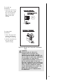
1
Heat-N-Glo Fireplace
Models:
6000 GDVFL
6000 XLS
Installers Guide
U.S. Patents 4,793,322; 4,875,464; 5,000,162 and Patents Pending
Canadian Patent 1,297,746
A.G.A. Design Certified/CGA Certified and
Underwriters Laboratories Listed. See
Approvals Tabel on Page 1.
WARNING
IF THE INFORMATION IN
THESE INSTRUCTIONS IS
NOT FOLLOWED EXACTLY, A
FIRE OR EXPLOSION MAY
RESULT CAUSING PROPERTY
DAMAGE, PERSONAL INJURY,
OR LOSS OF LIFE.
- Do not store or use gasoline or other flammable vapors and liquids in the vicinity of this
or any other appliance.
- What to do if you smell gas
Do not try to light any appliance.
Do not touch any electrical switch.
READ THIS MANUAL BEFORE INSTALLING
OR OPERATING THIS APPLIANCE. THIS
INSTALLERS GUIDE MUST BE LEFT WITH
APPLIANCE FOR FUTURE REFERENCE.
WARNING: IMPROPER
INSTALLATION, ADJUSTMENT,
ALTERATION, SERVICE OR
MAINTENANCE CAN CAUSE
INJURY OR PROPERTY DAMAGE.
REFER TO THIS MANUAL. FOR
ASSISTANCE OR ADDITIONAL
INFORMATION CONSULT A
QUALIFIED INSTALLER, SERVICE
AGENGY, OR THE GAS SUPPLIER.
Do not use any phone in your building.
Immediately call your gas supplier from a
neighbor's phone. Follow the gas supplier's
instructions.
If you cannot reach your gas supplier, call the
fire department.
- Installation and service must be performed by a
qualified installer, service agency, or the gas
supplier.
Printed in U.S.A.
Copyright 1997,
Heat-N-Glo Fireplace Products, Inc.
6665 West Highway 13, Savage, MN 55378
1.This appliance may be installed in an
aftermarket, permanently located,
manufactured (mobile) home, where
not prohibited by local codes.
2. This appliance is only for use with the
type of gas indicated on the rating
plate. This appliance is not convertible
for use with other gases, unless a
certified kit is used.
Please contact your Heat-N-Glo Fireplace
dealer for any questions or concerns. For the
number of your nearest Heat-N-Glo dealer,
please call 612-890-8367.
446-982-A 8/97
SAFETY AND WARNING INFORMATION
LIMITED 10 YEAR WARRANTY
HEAT-N-GLO GAS FIREPLACE PRODUCTS
In order to presumptively establish the dates to which your HEAT-N-GLO Limited 10 Year Warranty runs, you
must mail the completed warranty card to HEAT-N-GLO FIREPLACE PRODUCTS, INC., 6665 West
Highway 13, Savage, MN 55378, within 60 days of the date of fireplace installation. If you fail to do so, you
may be required to prove the date of installation before warranty work can be performed.
The warranty exclusions and limitations of liability are effective upon installation of the fireplace.
Subject to the conditions set forth herein, HEAT-N-GLO FIREPLACE PRODUCTS, INC. ("HEAT-N-GLO")
extends the following warranty with respect to HEAT-N-GLO Gas Fireplace Products.
If HEAT-N-GLO is reasonably satisfied that any part or portion of the fireplace covered by this Limited Warranty
is defective in material or workmanship under normal use and service as described in the Owners Guide,
HEAT-N-GLO will take the following actions:
1. If the defect is reported during the first year from the date of installation (stainless steel burners and fiber logs
are covered for 3 years), HEAT-N-GLO will replace or repair the defective components at its sole expense. The
decision whether to replace a component shall be made at HEAT-N-GLO's sole discretion. This Limited
Warranty does not cover components broken during shipping, misuse or careless handling. HEAT-N-GLO
shall be not responsible for any indirect, incidental, or consequential damages or for any costs other than those
incurred by HEAT-N-GLO to repair or replace the defective component. If components (including venting)
other than factory approved components are used, all warranty and liability on the fireplace is voided. Defects
reported after the first year will not be covered by warranty unless they fall within the purview of
paragraph 2 or 3 below.
2. If the following defects are reported during the second year after the date of installation, HEAT-N-GLO will
supply replacement parts at the current wholesale price: defective electrical or manual components, optional
components or accessories, and glass panels (not including glass panels broken during misuse or careless
handling). HEAT-N-GLO shall not be responsible for any labor, transportation or other costs. Furthermore,
HEAT-N-GLO shall not be liable for any indirect, incidental or consequential damages.
3. HEAT-N-GLO will replace or repair a defective firebox or heat exchanger, at any time during the 10 years from
the date of installation.
The decision whether to replace the defective component shall be made at
HEAT-N-GLO's sole discretion.
HEAT-N-GLO shall not be responsible for any indirect, incidental or
consequential damages or for any costs other than those incurred by HEAT-N-GLO to repair or replace the
defective component.
This Limited Warranty is the exclusive remedy available to you. If HEAT-N-GLO cannot effectively resolve a
warranty problem in an expedient and cost-effective manner, it can discharge its entire warranty liability by
refunding the price of the product to you.
Products made by other manufacturers, whether sold with the fireplace or added thereafter, are NOT covered by
this Limited Warranty. The use of other unauthorized components will make this warranty null and void. This
Limited Warranty will also be void if the appliance is not installed by a qualified installer in accordance with the
Installers Guide. Furthermore, the Limited Warranty will be void if the fireplace is not operated, at all times,
according to the Owners Guide furnished with the fireplace. Any service work must be performed by authorized
service representatives.
EXCEPT TO THE EXTENT PROVIDED BY LAW, NO OTHER EXPRESS OR IMPLIED WARRANTIES,
INCLUDING WARRANTIES OF MERCHANTABILITY OR FITNESS FOR A PARTICULAR PURPOSE, SHALL
APPLY TO THE FIREPLACE PRODUCT. In States that do not allow limitations on how long an implied warranty
lasts, or do not allow exclusion of indirect damages, those limitations or exclusions may not apply to you. You may
also have additional rights not covered in this Limited Warranty.
HEAT-N-GLO reserves the right to make changes at any time, without notice, in design, material, specifications
and prices. It also reserves the right to discontinue styles and products.
READ and UNDERSTAND all instructions carefully before starting the installation.
FAILURE TO FOLLOW these installation instructions may result in a possible fire
hazard and will void the warranty.
Prior to the first firing of the fireplace, READ the Using Your Fireplace section of the
Owners Guide.
DO NOT USE this appliance if any part has been under water. Immediately CALL a
qualified service technician to inspect the unit and to replace any part of the control
system and any gas control which has been underwater.
THIS UNIT IS NOT FOR USE WITH SOLID FUEL.
Installation and repair should be PERFORMED by a qualified service person. The
appliance and venting system should be INSPECTED before initial use and at least
annually by a professional service person. More frequent cleaning may be required due
to excessive lint from carpeting, bedding material, etc. It is IMPERATIVE that the units
control compartment, burners, and circulating air passageways BE KEPT CLEAN to
provide for adequate combustion and ventilation air.
Always KEEP the appliance clear and free from combustible materials, gasoline, and
other flammable vapors and liquids.
NEVER OBSTRUCT the flow of combustion and ventilation air. Keep the front of the
appliance CLEAR of all obstacles and materials for sevicing and proper operations.
Due to the high temperature, the appliance should be LOCATED out of traffic areas and
away from furniture and draperies. Clothing or flammable material SHOULD NOT BE
PLACED on or near the appliance.
Children and adults should be ALERTED to the hazards of high surface temperature and
should STAY AWAY to avoid burns or clothing ignition. Young children should be
CAREFULLY SUPERVISED when they are in the same room as the appliance.
These units MUST use one of the vent systems described in the Installing the Fireplace
section of the Installers Guide. NO OTHER vent systems or components MAY BE USED.
This gas fireplace and vent assembly MUST be vented directly to the outside and MUST
NEVER be attached to a chimney serving a separate solid fuel burning appliance. Each
gas appliance MUST USE a separate vent system. Common vent systems are
PROHIBITED.
INSPECT the external vent cap on a regular basis to make sure that no debris is
interfering with the air flow.
The glass door assembly MUST be in place and sealed, and the trim door assembly
MUST be in place on the fireplace before the unit can be placed into safe operation.
DO NOT OPERATE this appliance with the glass door removed, cracked, or broken.
Replacement of the glass door should be performed by a licensed or qualified service
person. DO NOT strike or slam the glass door.
The glass door assembly SHALL ONLY be replaced as a complete unit, as supplied by
the gas fireplace manufacturer. NO SUBSTITUTE material may be used.
DO NOT USE abrasive cleaners on the glass door assembly. DO NOT ATTEMPT to
clean the glass door when it is hot.
Turn off the gas before servicing this appliance. It is recommended that a qualified
service technician perform an appliance check-up at the beginning of each heating
season.
i
Any safety screen or guard removed for servicing must be replaced before operating
this appliance.
Safety and Warning Information ...................... i
Section 1: Approvals and Codes ..................... 1
Approval Listings and Codes ................................ 1
Appliance Certification ...................................... 1
Installation Codes ............................................... 1
High Altitude Installations ................................ 1
Section 2: Getting Started ................................ 2
Introducing the Heat-N-Glo Gas Fireplaces........ 2
Pre-installation Preparation ................................... 2
Table of
Contents
Section 3: Installing the Fireplace .................. 5
Step 1 Locating the Fireplace ............................. 5
Step 2 Framing the Fireplace .............................. 6
Step 3 Installing the Vent System ...................... 7
A. Vent System Approvals ................................ 7
B. Installing Vent Components ...................... 13
C. Vent Termination ......................................... 18
Step 4 Positioning, Leveling, and
Securing the Fireplace ........................... 23
Step 5 The Gas Control Systems ...................... 23
Step 6 The Gas Supply Line ............................. 24
Step 7 Gas Pressure Requirements .................. 25
Step 8 Wiring the Fireplace .............................. 26
Step 9 Finishing .................................................. 28
Step 10 Installing Trim, Logs, and
Ember Material ....................................... 29
Installing the Trim ............................................. 29
Positioning the Logs ......................................... 30
Placing the Ember Material ............................. 30
Step 11 Before Lighting the Fireplace .............. 32
Step 12 Lighting the Fireplace .......................... 32
After the Installation ............................................. 32
Section 4: Maintenance and Servicing ........ 33
Section 5: Replacement Parts
and Accessories ............................. 35
Replacement Parts ................................................. 35
Accessories ............................................................. 38
ii
1
Approval Listings
and Codes
MODEL
6000GDVFL
Approvals
and Codes
Appliance Certification
The Heat-N-Glo fireplace models discussed in this
Installers Guide have been tested to certification
standards and listed by the applicable laboratories.
LABORATORY
A.G.A./CGA
and
Underwriters
Laboratories
6000XLS
A.G.A./CGA
and
Underwriters
Laboratories
TYPE
CERTIFICATION
STANDARD
Direct Vent
Decorative
ANSI Z21.50CGA2.22
Direct Vent
Wall Furnace
ANSI Z21.44/IR#41/CAN1-2.19
Installation Codes
The fireplace installation must conform to local codes. Before installing the
fireplace, consult the local building code agency to ensure that you are in
compliance with all applicable codes, including permits and inspections.
In the absence of local codes, the fireplace installation must conform to the
National Fuel Gas Code ANSI Z223.1 (in the United States) or the CAN/CGAB149 Installation Codes (in Canada). The appliance must be electrically
grounded in accordance with local codes or, in the absence of local codes with
the National Electric Code ANSI/NFPA No. 70 (in the United States), or to the
CSA C22.1Canadian Electric Code (in Canada).
These models may be installed in a bedroom or bed-sitting room in the U.S.A.
and Canada.
High Altitude Installations
A.G.A./CGA Design Certified and U.L. Listed gas fireplaces are tested and
approved for elevations from 0 to 2,000 feet in the U.S.A. and from 0 to 4,500
feet in Canada.
When installing this fireplace at an elevation above 2,000 feet (in the United
States), it may be necessary to decrease the input rating by changing the
existing burner orifice to a smaller size. Input should be reduced four percent
(4%) for each 1,000 feet above sea level, unless the heating value of the gas has
been reduced, in which case this general rule will not apply. To identify the proper
orifice size, check with the local gas utility.
When installing this fireplace at an elevation between 2,000 and 4,500 feet (in
Canada), the input rating must be reduced by ten percent (10%).
When installing this fireplace at an elevation above 4,500 feet (in Canada), check
with local authorities.
Consult your local gas utility for assistance in determining the proper orifice for
your location.
1
Introducing the
Heat-N-Glo
Gas Fireplaces
Heat-N-Glo direct vent gas fireplaces are designed to
operate with all combustion air siphoned from outside
of the building and all exhaust gases expelled to the
outside.
The information contained in this Installers Guide,
unless noted otherwise, applies to all models and gas
control systems.
Gas fireplace diagrams, including the dimensions, are
shown in this section.
Pre-installation
Preparation
This gas fireplace and its components are tested and
safe when installed in accordance with this Installers
Guide. Report to your dealer any parts damaged in
shipment, particularly the condition of the glass. Do
not install any unit with damaged, incomplete, or
substitute parts.
2
Getting
Started
The vent system components and trim doors are
shipped in separate packages. The gas logs are
factory installed (Model 6000GDVFL) and are
packaged separately and must be field installed
(Model 6000XLS). Read all of the instructions
before starting the installation. Follow these
instructions carefully during the installation to
ensure maximum safety and benefit. Failure to
follow these instructions will void the owners
warranty and may present a fire hazard.
The Heat-N-Glo Fireplace Products, Inc. Warranty will
be voided by, and Heat-N-Glo Fireplace Products, Inc.
disclaims any responsibility for, the following actions:
Installation of any damaged fireplace or vent system
component.
Modification of the fireplace or direct vent system.
Installation other than as instructed by Heat-N-Glo
Fireplace Products, Inc.
Improper positioning of the gas logs or the glass
door.
Installation and/or use of any component part not
manufactured and approved by Heat-N-Glo Fireplace Products, Inc., not withstanding any independent testing laboratory or other party approval of
such component part or accessory.
ANY SUCH ACTION MAY POSSIBLY CAUSE A
FIRE HAZARD.
2
When planning a fireplace installation, its necessary to determine:
Where the unit is to be installed.
The vent system configuration to be used.
Gas supply piping.
Electrical wiring.
Framing and finishing details.
Whether optional accessoriesdevices such as a fan, wall switch, or remote
controlare desired.
If the fireplace is to be installed on carpeting or tile, or on any combustible
material other than wood flooring, the fireplace should be installed on a metal or
wood panel that extends the full width and depth of the fireplace.
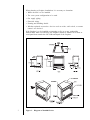
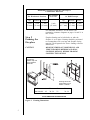
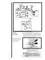
3
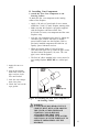
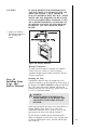
Figure 1. Diagram of the6000 Series
Step 1
Locating the
Fireplace
The diagram below shows space and clearance
requirements for locating a fireplace within a room.
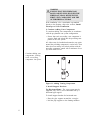
3
Installing the
Fireplace
Figure 2. Fireplace Dimensions, Locations, and
Space Requirements
Clearance Requirements
The top, back, and sides of the fireplace are defined
by stand-offs.
Minimum Clearances from the Fireplace to
Combustible Materials
Glass
Front
36 inches
(914 mm)
Floor
0
Back of
Fireplace
Sides of
Fireplace
Top of
Fireplace
Ceiling
1/2 inch
(13 mm)
1/2 inch
(13 mm)
3-1/2 inches
(89 mm)
31 inches
(787 mm)
The minimum clearance to a perpendicular wall
extending past the face of the fireplace is one inch (25
mm).
For 6000 Series Models, the back of the fireplace may
be recessed 21-1/2 inches (546 mm) into
combustible construction.
4
Minimum Clearances from the Vent Pipe to
Combustible Materials
For Horizontal Sections
Top
Bottom
For Vertical
Se c tio ns
Sides
3 inches 1 inch
1 inch
(75 mm) (25 mm) (25 mm)
At Wall Firestops
Top
1 inch
(25 mm)
Bottom
Sides
2-1/2 inches 1/2 inch
1 inch
(63.7 mm) (13 mm) (25 mm)
For minimum clearances, see the direct vent
termination clearance diagrams on pages 19 and 21 in
this section.
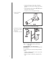
Step 2
Framing the
Fireplace
Fireplace framing can be built before or after the
fireplace is set in place. Framing should be positioned
to accommodate wall coverings and fireplace facing
material. The diagram below shows framing reference
dimensions.
CAUTION
MEASURE FIREPLACE DIMENSIONS, AND
VERIFY FRAMING METHODS AND WALL
COVERING DETAILS, BEFORE FRAMING
CONSTRUCTION BEGINS.
The framing
headers may rest
on the fireplace
stand-offs.
B
C
A
Framing should be
constructed of 2 X 4
lumber or heavier.
Model
A
B
C
D
6000 Models
42
38-1/4
22
26-1/4
NOTE: DIMENSIONS SHOWN IN INCHES
Figure 3. Framing Dimensions
5
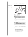
Step 3
Installing the
Vent System
A. Vent System Approvals
These appliances are approved to use D-series direct
vent pipe components and terminations. Approved
vent system components are labeled for identification.
NO OTHER VENTING SYSTEMS OR
COMPONENTS MAY BE USED. Detailed
installation instructions are included with each vent
termination kit and should be used in conjunction with
this Installers Guide. The drawing below shows vent
system components and terminations.
Identifying Vent Components
The vent systems installed on this gas fireplace may
include one, two, or three 90° elbow assemblies. The
relationships of vertical rise to horizontal run in vent
configurations using 90° elbows MUST BE strictly
adhered to. The rise to run relationships are shown in
the venting drawings and tables. Refer to the
diagrams on the next several pages.
Vent system
termination kits
Vent system components
Figure 4. Vent Components and Terminations
6
DV-45D
DV-90D
6-7/16"
6 7/16
(164
mm)
6-5/32"
6 5/32
(156
mm)
88-1/2"
1/2
(216 mm)
7-3/8"
8-1/2"
8 /12
(216 mm)
5-7/8"
7 (187
3/8 mm)5(149
7/8mm)
11-5/8"
11 5/8
(295 mm)
11-1/16"
11 1/16
(281 mm)
6-1/2"
6 1/2
(165 mm)
8-5/8"
8(220
5/8mm)
5-1/16"
5 1/16
(129 mm)
8-5/8"
11-15/16"
11 15/16
(303 mm)
8(220
5/8mm)
DV-48D
DV-36D
47-3/4"
47
(1.23/4
m)
35-3/4"
35mm)
3/4
(908
DV-12D
DV-09D
11-3/4"
11 3/4
(298 mm)
DV-06D
8-3/4"
8 3/4
(222 mm)
NOTE: PIPES
1 3/8 INCHES
(34.93 mm)
AT
EACH
JOINT.JOINT.
NOTE:OVERLAP
PIPES OVERLAP
1-3/8 INCHES
(34.93
mm)
AT EACH
Figure 5. D-Series Direct Vent Component Specifications
(5-inch inner pipe/8 5/8-inch outer pipe)
7
5-3/4"
5 3/4
(146 mm)
HORIZONTAL VENTING
Kit No.
H
Max. Run
DVK-01D
DVK-01TRD
24" (610 mm)
Figure 6. Corner Installation
Models 6000XLS, and 6000GDVFL are tested and
approved to use 45° elbows in corner installations.
However, 90° elbows will result in better performance.
8
VENTING WITH ONE (1) 90° ELBOW
1´
2´
3´
4´
MIN.
MIN.
MIN.
MIN.
(305 mm)
(610 mm)
(914 mm)
(1.22 m)
40´ MAX. (12.4 m)
Figure 7. Venting with One 90° Elbow
9
2´
4´
6´
8´
MAX.
MAX.
MAX.
MAX.
(610 mm)
(1.22 m)
(1.86 m)
(2.48 m)
8´ MAX. (2.48 m)
VENTING WITH TWO (2) 90° ELBOWS
V
1´ MIN. (305 mm)
2´ MIN. (610 mm)
3´ MIN. (914 mm)
4´ MIN. (1.22 m)
H
2´ MAX. (610 mm)
4´ MAX. (1.22 m)
6´ MAX. (1.86 m)
8´ MAX. (2.48 m)
H + H1
6´ MAX. (1.86 m)
12´ MAX. (3.72 m)
18´ MAX. (5.58 m)
24´ MAX. (7.74 m)
20´ MAX. (6.2 m)
8´ MAX. (2.48 m)
24´ MAX. (7.74 m)
(20´ (6.2 m) CANADA)
Figure 8. Venting with Two 90° Elbows
10
VENTING WITH THREE (3) 90° ELBOWS
1´ MIN. (305 mm)
2´ MIN. (610 mm)
3´ MIN. (914 mm)
4´ MIN. (1.22 m)
2´ MAX. (610 mm)
4´ MAX. (1.22 m)
6´ MAX. (1.86 m)
8´ MAX. (2.48 m)
5´ MAX. (1.52 mm)
10´ MAX. (3.1 m)
15´ MAX. (4.65 m)
20´ MAX. (6.2 m)
8´ MAX. (2.48 m)
20´ MAX. (6.2 m)
NOTE: V + V, MAX. 40´ (12.4 m)
VENTING WITH THREE (3) 90° ELBOWS
1´ MIN. (305 mm)
2´ MIN. (610 mm)
3´ MIN. (914 mm)
4´ MIN. (1.22 m)
2´ MAX. (610 mm)
4´ MAX. (1.22 m)
6´ MAX. (1.86 m)
8´ MAX. (2.48 m)
5´ MAX. (1.52 mm)
10´ MAX. (3.1 m)
15´ MAX. (4.65 m)
20´ MAX. (6.2 m)
20´ MAX. (6.2 m)
8´ MAX. (2.48 m)
20´ MAX. (6.2 m)
Figure 9. Venting with three 90° elbows
11
B. Installing Vent Components
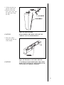
1. Attach the First Vent Component to the
Starting Collars
To attach the first vent component to the starting
collars of the fireplace:
Apply a 3/8 inch (9.5 mm) bead of stove cement
around the 5 inch (127 mm) fireplace starting collar.
Make sure that the fireplace rope gasket supplied
with the fireplace seals between the first
8-5/8 inch (219 mm) vent component and the outer
fireplace wrap.
Lock the vent components into place by sliding the
concentric pipe sections with four (4) equally
spaced interior beads into the fireplace collar or
previously installed component end with four (4)
equally spaced indented sections.
When the internal beads of each 8-5/8 inch
(219 mm) outer pipe line up, rotate the pipe section
clockwise about one-quarter (1/4) turn. The vent
pipe is now locked together.
The first 90° elbow installed in the vent system of a
rear venting fireplace MUST BE in a vertical position.
1. Apply the stove cement.
2. Line up the internal
beads and rotate the
pipe sections clockwise until locked.
STARTING
COLLAR
3. Lock the vent components into place.
4. Check the seal on the
rope gasket.
FIRST
VENT
COMPONENT
STOVE
SEALANT
BEAD
3/8
(9.5 mm)
3/8" INCH
(9.5 mm)
1 INCH (25.4 mm)
Figure 10. Attaching the First Vent Component to
the Starting Collars
WARNING
A 3/8 INCH (9.5 MM) BEAD OF STOVE
CEMENT MUST BE PLACED AROUND
THE 5 INCH (127 MM) FIREPLACE
STARTING COLLAR BEFORE
ATTACHING THE FIRST VENT
COMPONENT. FAILURE TO SEAL THIS
JOINT MAY CAUSE THE FIREPLACE TO
OPERATE IMPROPERLY. SEE THE
DIAGRAM .
12
WARNING
ENSURE THAT THE FIBERGLASS
ROPE GASKET SUPPLIED WITH THE
FIREPLACE SEALS BETWEEN THE
FIRST VENT COMPONENT AND THE
OUTER FIREPLACE WRAP.
If the installation is for a termination cap attached
directly to the fireplace, skip to the sections, Install
Firestops and Vent Termination.
2. Continue Adding Vent Components
To continue adding vent components in accordance
with the pre-planned vent system configuration:
Ensure that each succeeding vent component is
securely fitted and locked into the preceding component in the vent system.
90° elbows may be installed and rotated to any point
around the preceding components vertical axis. If an
elbow does not end up in a locked position with the
preceding component, attach with a minimum of two
(2) sheet metal screws.
Continue adding vent
components, locking
each succeeding
component into place.
Figure 11. Adding Venting Components
3. Install Support Brackets
For Horizontal Runs - The vent system must be
supported every five (5) feet of horizontal run by a
horizontal pipe support.
To install support brackets for horizontal runs:
Place the pipe supports around the vent pipe.
Nail the pipe supports to the framing members.
13
For Vertical Runs - The vent system must be
supported every eight (8) feet (2.4 m) above the
fireplace flue outlet by wall brackets.
To install support brackets for vertical runs:
Attach wall brackets to the vent pipe and secure the
wall bracket to the framing members with nails or
screws.
Use wall brackets to
support vertical runs
every 8 feet (2.4 m)
above the fireplace flue
outlet.
WALL BRACKET
WALL STUD
8 FT. (2.4 m)
FLUE
OUTLET
1 INCH MIN.
(25.4 mm)
Figure 12. Installing Support Brackets
4. Install Firestops
For Horizontal Runs - Firestops are REQUIRED on
both sides of a combustible wall through which the
vent passes.
NOTE
Model DVK-01TRD does not need an exterior
firestop on an exterior combustible wall.
To install firestops for horizontal runs that pass
through either interior or exterior walls:
Cut a 12-inch by 12-inch (305 mm X 305 mm) hole
through the wall. The center of the hole is one (1)
inch (25.4 mm) above the center of the horizontal
vent pipe.
14
Position the firestops on both sides of the hole
previously cut and secure the firestops with nails or
screws.
The heat shields of the firestops MUST BE placed
towards the top of the hole.
Continue the vent run through the firestops.
1. Cut the 12-inch by
12-inch hole.
12"
(305 mm)
12"
(305 mm)
1" (25.4 mm)
VENT PIPE
Figure 13. 12" x 12" Hole and Vent Pipe
2. Position the firestops.
3. Place the heat shield
to the top.
HEAT SHIELD
4. Continue the vent run.
TRIM HEAT
SHIELD IF TOO
LONG, ADD TO
SHIELD IF TOO
SHORT.
EXTERIOR
FIRESTOP
INTERIOR
FIRESTOP
Figure 14. Heat Shield, Interior and Exterior
Firestops
For Vertical Runs - One ceiling firestop is
REQUIRED at the hole in each ceiling through which
the vent passes.
To install firestops for vertical runs that pass through
ceilings:
Position a plumb bob directly over the center of the
vertical vent component.
15
Mark the ceiling to establish the centerpoint of the
vent.
Drill a hole or drive a nail through this centerpoint.
Check the floor above for any obstructions, such as
wiring or plumbing runs.
Reposition the fireplace and vent system, if necessary, to accommodate the ceiling joists and/or
obstructions.
Cut an 11-inch X 11-inch (280 mm X 280 mm) hole
through the ceiling, using the centerpoint previously
marked.
Frame the hole with framing lumber the same size
as the ceiling joists.
1. Cut the 11-inch by
11-inch hole.
11" (280 mm)
2. Add the new framing
members.
11" (280 mm)
CHIMNEY
HOLE
NEW
FRAMING
MEMBERS
EXISTING CEILING
JOISTS
CEILING
Figure 15. 11" x 11" Hole and New Framing
Members
If the area above the ceiling is NOT an attic, position
and secure the ceiling firestop on the ceiling side of
the previously cut and framed hole.
This shows a ceiling
installation.
JOIST
CEILING
NAILS (4 REQUIRED)
CEILING FIRESTOP
Figure 16. Ceiling Firestop (Ceiling Side)
16
If the area above the ceiling IS an attic, position and
secure the firestop on top of the previously framed
hole.
This shows an attic
installation.
NAILS (4 REQUIRED)
1. Keep insulation away
from the vent pipe at
least 1 inch (25 mm).
RAFTER
CEILING
CEILING FIRESTOP
Figure 17. Attic Firestop
C. Vent Termination
For Horizontal Terminations - To attach and secure
the termination to the last section of horizontal vent:
Rotate and interlock the ends as described at the
beginning of the Installing Vent Components section.
The termination kit should pass through the wall
firestops from the exterior of the building.
Adjust the termination cap to its final exterior position on the building.
WARNING
THE TERMINATION CAP MUST BE
POSITIONED SO THAT THE ARROW IS
POINTING UP.
For roundcap termination kits:
Use the exterior pipelock hole provided on the round
flange of the wall firestop to secure the vent pipe in
place.
For trapezoidal cap termination kits:
Using screws, secure the cap to the exterior wall
through the flanges built into the cap.
Use a high-temperature sealant or fiberglass rope
gasket to seal between the 8-5/8 inch
(219 mm) pipe and exterior firestop.
17
For round cap
termination:
1. Secure the 8-5/8 inch
(219 mm) pipe, using
the exterior pipelock
hole on the round
flange of the wall
firestop.
For trapezoidal
termination:
1. Screw the cap to the
exterior wall through
the flanges in the cap.
2. Seal the joint between
the pipe and the
exterior firestop.
Figure 18. Round and Trapezoid Termination
Caps
WARNING
THE BOTTOM OF THE VENT
TERMINATION CAP MUST BE A
MINIMUM OF 12 INCHES (305 MM)
ABOVE GROUND LEVEL (GRADE). THE
TOP OF THE CAP MUST BE A MINIMUM
OF 18 INCHES (457 MM) BELOW
COMBUSTIBLE MATERIAL, SUCH AS A
DECK, AND THE SIDE OF THE CAP
MUST BE A MINIMUM OF 6 INCHES (152
MM) AWAY FROM A PARALLEL OUTSIDE
WALL. VENTING TERMINALS SHALL
NOT BE RECESSED INTO A WALL OR
SIDING. SEE THE FOLLOWING
DIAGRAM FOR VENT TERMINATION
CLEARANCES.
18
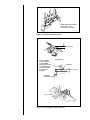
G
v
A
D
H
E
v
L
v
C
B
v
F
openable
fixed closed
v
B
v
v
B
I
B
M
v
X
J or K
A
V
=VENT TERMINAL
X =AIR SUPPLY INLET
123
123
123
123 =AREA WHERE TERMINAL IS NOT PERMITTED
123
A
= 12"
clearances above grade, veranda, porch, deck or balcony
B
= 12"
clearances to window or door that may be opened
C
= 9" (U.S.A.)
12" (Canada)
clearance to permanently closed window
D
= 18"
vertical clearance to ventilated soffit located above the
terminal within a horizontal distance of 2 feet (60 cm)
from the center-line of the terminal
E
= 18"
clearance to unventilated soffit
F
= 9"
clearance to outside corner
G
= 6"
clearance to inside corner
H
= 3 ft. (Canada)
not to be installed above a gas meter/regulator assembly
within 3 feet (90 cm) horizontally from the center-line of
the regulator
I
= 3 ft. (U.S.A.)
6 ft. (Canada)
clearance to service regulator vent outlet
J
= 9" (U.S.A.)
12" (Canada)
clearance to non-mechanical air supply inlet to building
or the combustion air inlet to any other appliance
K
= 3 ft. (U.S.A.)
6 ft. (Canada)
clearance to a mechanical air supply inlet
*L
= 7 ft.
clearance above paved sidewalk or a paved driveway
located on public property
**M = 18"
clearance under veranda, porch, deck or balcony
*
a vent shall not terminate directly above a sidewalk or paved driveway which is
located between two single family dwellings and serves both dwellings.
**
only permitted if veranda, porch, deck or balcony is fully open on a minimum of
2 sides beneath the floor.
NOTE: Local Codes or Regulations may require different clearances.
Figure 19. Vent Termination Minimum Clearances
CAUTION
19
IF EXTERIOR WALLS ARE FINISHED WITH
VINYL SIDING, IT IS NECESSARY TO INSTALL
THE VINYL PROTECTOR KIT (VPK-DV) TO THE
TOP OF THE EXTERIOR FIRESTOP (FOR ALL
ROUND TERMINATION CAPS).
For Vertical Terminations - To locate the vent and
install the vent sections:
Locate and mark the vent centerpoint on the underside of the roof, and drive a nail through the
centerpoint.
Make the outline of the roof hole around the
centerpoint nail.
The size of the roof hole framing dimensions
depend on the pitch of the roof. There MUST BE a
1-inch (25.4 mm) clearance from the vertical vent
pipe to combustible materials.
Mark the roof hole accordingly.
Cover the opening of the installed vent pipes.
Cut and frame the roof hole.
Use framing lumber the same size as the roof
rafters and install the frame securely. Flashing
anchored to the frame must withstand heavy winds.
Continue to install concentric vent sections up
through the roof hole (for inside vent installations) or
up past the roof line until you reach the appropriate
distance above the roof (for outside terminations).
WARNING
MAJOR U.S. BUILDING CODES
SPECIFY MINIMUM CHIMNEY AND/OR
VENT HEIGHT ABOVE THE ROOF TOP.
THESE MINIMUM HEIGHTS ARE
NECESSARY IN THE INTEREST OF
SAFETY. SEE THE FOLLOWING
DIAGRAM FOR MINIMUM HEIGHTS,
PROVIDED THE TERMINATION CAP IS
AT LEAST TWO (2) FEET FROM A
VERTICAL WALL AND 2-FEET BELOW A
HORIZONTAL OVERHANG.
NOTE
This also pertains to vertical vent systems installed
on the outside of the building.
20
To seal the roof hole, and to divert rain and snow from
the vent system:
Attach a flashing to the roof using nails, and use a
non-hardening mastic around the edges of the
flashing base where it meets the roof.
Attach a storm collar over the flashing joint to form a
water-tight seal. Place non-hardening mastic
around the joint, between the storm collar and the
vertical pipe.
Slide the termination cap over the end of the vent
pipe and rotate the pipe clockwise 1/4 turn.
1. Attach the flashing
and apply sealant
around the edges of
the flashing base.
TERMINATION
CAP
2. Attach the storm
collar over the flashing
joint and apply sealant
between the storm
collar and vertical
pipe.
Roof Pitch
flat to 6/12
6/12 to 7/12
over 7/12 to 8/12
over 8/12 to 9/12
over 9/12 to 10/12
over 10/12 to 11/12
over 11/12 to 12/12
over 12/12 to 14/12
over 14/12 to 16/12
over 16/12 to 18/12
over 18/12 to 20/12
over 20/12 to 21/12
H (min.) ft.
1.0
1.25
1.5
2.0
2.5
3.25
4.0
5.0
6.0
7.0
7.5
8.0
Figure 20. Minimum Height from Roof to Lowest
Discharge Opening
21
Step 4
Positioning,
Leveling, and
Securing the
Fireplace
The diagram below shows how to properly position,
level, and secure the fireplace.
1. Place the fireplace
into position.
2. Level the fireplace
from side to side and
from front to back.
3. Shim the fireplace
with non-combustible material, such
as sheet metal, as
necessary.
4. Secure the fireplace
to the framing by
nailing or screwing
Figure 21. Proper Positioning, Leveling, and
Securing of a Fireplace
Step 5
The Gas Control
Systems
WARNING
THIS UNIT IS NOT FOR USE WITH
SOLID FUEL.
Two types of gas control systems are used with
these models: Standing Pilot Ignition and Direct
Spark Ignition (DSI). Model 6000XLS has Standing
Pilot Ignition only.
Standing Pilot Ignition System
This system includes millivolt control valve, standing
pilot, thermopile/thermocouple flame sensor, and
piezo ignitor.
WARNING
110-120 VAC MUST NEVER BE
CONNECTED TO A CONTROL VALVE
IN A MILLIVOLT SYSTEM.
Direct Spark Ignition (DSI) System
This system includes a 24V control valve, electronic
module, transformer, and spark ignitor/flame sensor.
WARNING
110-120 VAC MUST BE WIRED TO THE
FIREPLACE JUNCTION BOX IN A DSI
SYSTEM.
WARNING
DIRECT VENT PROPANE MODELS
WITH DSI CONTROL SYSTEMS
CANNOT BE USED IN CANADA.
22
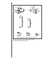
DSI IGNITION
STANDING PILOT
IGNITOR
3/8" (10 mm)
1/2" (13 mm)
3/16" (5 mm)
Figure 22. Gas Controls Systems
Step 6
The Gas
Supply Line
NOTE: Have the gas supply line installed by a
qualified service technician in accordance with all
building codes.
NOTE: Before the first firing of the fireplace, the
gas supply line should be purged of any trapped air.
NOTE: Consult local building codes to properly size
the gas supply line leading to the 1/2 inch
(13 mm) hook-up at the unit.
This gas fireplace is designed to accept a 1/2 inch
(13 mm) gas supply line.
To install the gas supply line:
A listed 1/2 inch (13 mm) manual shut-off valve and a
listed flexible gas connector are connected to the 1/2
inch (13 mm) inlet of the control valve.
A 1/8 inch (3 mm) N.P.T. plugged tapping, accessible
for test gauge connection, should be provided for in
the gas supply line leading to the units shut-off valve.
Locate the gas line access hole in the outer casing of
the fireplace.
Open the fireplace lower grille, insert the gas supply
line through the gas line hole, and connect it to the
shut-off valve.
When attaching the pipe, support the control so that
the lines are not bent or torn.
After the gas line installation is complete, use a soap
solution to carefully check all gas connections for
leaks.
WARNING
DO NOT USE AN OPEN FLAME TO
CHECK FOR GAS LEAKS.
23
At the gas line access hole, use insulation to repack the space around the gas pipe.
Insert insulation from the outside of the fireplace
and pack the insulation tightly to totally seal between the pipe and the outer casing.
The gas line should be
installed by a qualified
service technician.
Figure 23. Gas Supply Line
Step 7
Gas Pressure
Requirements
Pressure requirements for Heat-N-Glo gas fireplaces
are shown in the table below.
Pressure
Natural Gas
Propane
Minimum
Inlet Pressure
5.0 inches
w.c.
11.0 inches
w.c.
Maximum Inlet
Gas Pressure
14.0 inches
w.c.
14.0 inches
w.c.
Manifold
Pressure
3.5 inches
w.c.
10.0 inches
w.c.
A one-eighth (1/8) inch (3 mm) N.P.T. plugged tapping
is provided on the outlet side of the gas control for a
test gauge connection to measure the manifold
pressure. To measure inlet pressure, provisions must
be made to attach a test gauge to a one-eighth (1/8)
inch (3 mm) N.P.T. plugged tapping immediately
upstream of the gas supply connection to the
fireplace.
The fireplace and its individual shut-off valve must be
disconnected from the gas supply piping system
during any pressure testing of the system at test
pressures in excess of one-half (1/2) psig (3.5 kPa).
The fireplace must be isolated from the gas supply
piping system by closing its individual shut-off valve
during any pressure testing of the gas supply piping
system at test pressures equal to or less than onehalf (1/2) psig (3.5 kPa).
24
Step 8
Wiring the
Fireplace
NOTE: Electrical wiring must be installed by a
licensed electrician.
Caution: Disconnect remote controls if you are
absent for extended time periods. This will
prevent accidental fireplace operation.
For Standing Pilot Ignition Wiring
Appliance Requirements
This appliance DOES NOT require 110-120 VAC to
operate.
WARNING
DO NOT CONNECT 110-120 VAC TO THE
GAS CONTROL VALVE OR REMOTE
WALL SWITCH OR THE APPLIANCE WILL
MALFUNCTION AND THE VALVE WILL BE
DESTROYED.
Optional Accessories
Optional fan and remote control kits require that 110120 VAC be wired to the factory installed junction box
before the fireplace is permanently installed.
Remote Wall Switch
Position the remote wall switch in the desired position
on a wall. Run a maximum of 25 feet (7.8 m) or less
length of 18 A.W.G. minimum wire and connect it to
the fireplace ON/OFF switch pigtails.
WARNING
DO NOT CONNECT 110-120 VAC TO THE
REMOTE WALL SWITCH OR THE
CONTROL VALVE WILL BE
DESTROYED.
CAUTION
LABEL ALL WIRES PRIOR TO DISCONNECTION
WHEN SERVICING CONTROLS. WIRING
ERRORS CAN CAUSE IMPROPER AND
DANGEROUS OPERATION. VERIFY PROPER
OPERATION AFTER SERVICING.
Figure 24. Standing Pilot Ignition Wiring Diagram
25
FAN WIRING DIAGRAM
NOTE: IF ANY OF THE ORIGINAL WIRE
AS SUPPLIED WITH THE APPLIANCE
MUST BE REPLACED, IT MUST BE
REPLACED WITH TYPE 105 DEGREE C
RATED WIRE.
VARIABLE SPEED CONTROL
BLK
BLK
JUNCTION BOX
BLK
BLK
BLOWER RECEPTACLE
BLK
BLK
BLK
BLK
WHT
WHT
BLK
GROUND
TEMPERATURE
SENSOR SWITCH
BLOWER
GRN
BLK
WHT
110-120 VAC
JUNCTION
BOX
FAN
TEMPERATURE
SENSOR SWITCH
SPEED CONTROL
(RHEOSTAT)
Figure 25. Fan Wiring Diagram
For Direct Spark Ignition (DSI) Wiring
Appliance Requirements
This appliance requires that 110-120 VAC be wired to
the factory installed junction box. Maintain correct
polarity when wiring the junction box.
Optional Accessories
Optional fan and remote control kits require that 110120 VAC be wired to the fireplace junction box.
Remote Wall Switch
Position the remote wall switch in the desired position
on a wall. Run a maximum of 25 feet
(7.8 m) or less of 16 A.W.G. minimum wire and
connect it to the fireplace ON/OFF switch pigtails.
NOTE
Electrical wiring must be installed by a licensed
electrician.
CAUTION
LABEL ALL WIRES PRIOR TO DISCONNECTION
WHEN SERVICING CONTROLS. WIRING
ERRORS CAN CAUSE IMPROPER AND
DANGEROUS OPERATION. VERIFY PROPER
OPERATION AFTER SERVICING.
26
Figure 26. Direct Spark Ignition (DSI) Wiring Diagram
Step 9
Finishing
The following diagram shows the minimum vertical
and corresponding maximum horizontal dimensions
of fireplace mantels or other combustible projections
above the top front edge of the fireplace. See Figures
2 and 3 for other fireplace clearances.
Only non-combustible
materials may be used
to cover the black
fireplace front.
12"
11"
10"
9"
8"
7"
6"
11"
5"
4"
6" 7"
3"
2"
1"
3" 3.5"
4"
8" 9"
10"
4.5" 5"
1.5"
TOP FRONT EDGE
OF FIREPLACE
NOTE: ALL DIMENSIONS SHOWN
IN INCHES.
Figure 27. Minimum Vertical and Maximum
Horizontal Dimensions of
Combustibles above Fireplace
27
WARNING
WHEN FINISHING THE FIREPLACE,
NEVER OBSTRUCT OR MODIFY THE
AIR INLET/OUTLET GRILLES IN ANY
MANNER.
CAUTION
IF JOINTS BETWEEN THE FINISHED WALLS
AND THE FIREPLACE SURROUND (TOP AND
SIDES) ARE SEALED, A 300° F. MINIMUM
SEALANT MATERIAL MUST BE USED. THESE
JOINTS ARE NOT REQUIRED TO BE SEALED.
ONLY NON-COMBUSTIBLE MATERIAL (USING
300° F. MINIMUM ADHESIVE, IF NEEDED) CAN
BE APPLIED AS FACING TO THE FIREPLACE
SURROUND. SEE THE DIAGRAM SHOWN
BELOW.
1. Apply non-combustible facing material to
the fireplace surround.
Figure 28. Sealant Material
Hearth Extensions
A hearth extension may be desirable for aesthetic
reasons. However, ANSI or CAN/CGA testing
standards do not require hearth extensions for gas
fireplace appliances.
Step 10
Installing Trim,
Logs, and
Ember Material
Installing the Trim
Combustible materials may be brought up to the
specified clearances on the side and top front edges of
the fireplace, but MUST NEVER overlap onto the front
face. The joints between the finished wall and the
fireplace top and sides can only be sealed with a 300°
F. (149° C) minimum sealant.
WARNING
WHEN FINISHING THE FIREPLACE,
NEVER OBSTRUCT OR MODIFY THE
AIR INLET/OUTLET GRILLES IN ANY
MANNER.
Install optional marble and brass trim surround kits as
desired. Marble, brass, brick, tile, or other noncombustible materials can be used to cover up the
gap between the sheet rock and the fireplace.
Do not obstruct or modify the air inlet/outlet grilles.
When overlapping on both sides, leave enough space
so that the bottom grille can be lowered and the trim
door removed.
28
Positioning the Logs
If the gas logs have been factory installed they should
not need to be positioned.
If the logs have been packaged separately, refer to the
installation instructions that accompany the logs.
Save the log instructions with this manual.
If sooting occurs, the logs might need to be
repositioned slightly to avoid excessive flame
impingement.
Placing the Ember Material
Two separate bags of ember material are shipped with
this gas fireplace:
The bag labeled Golden Ember (GE-93) is flame
colorant material.
The bag labeled Glowing Ember (050-721) is
standard glowing ember material.
To place the ember material:
Remove the wing nuts and glass clips or tension
springs around the glass door.
Remove the glass door from the unit.
Cover the top of the burner with a single layer of
ember material. Then sprinkle GE-93 on top of the
burner.
Save the remaining ember materials for use during
fireplace servicing.
Replace the glass door and a front trim door on the
unit (see Replacement Parts Section of the
manual.)
Replace the wing nut, glass clips, and tension
springs.
Hand tighten the wing nuts.
29
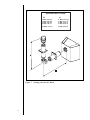
1. Lift the trim door up
and out of the unit.
2. Remove the wing
nuts, glass clips, and
the glass door from
the unit.
Figure 29. Glass Assembly
CAUTION
HAND TIGHTEN THE WING NUTS, BUT BE
CAREFUL NOT TO OVERTIGHTEN.
1. Place the ember
material onto the top
of the burner.
Figure 30. Placement of the Ember Material
CAUTION
IT IS STRONGLY RECOMMENDED THAT TRIM
DOORS WITH OPTIIONAL MESH SCREENS BE
INSTALLED ON PROPANE MODELS.
30
Step 11
Before Lighting
the Fireplace
Before lighting the fireplace, be sure to do the
following:
Review safety warnings and cautions
Read the Safety and Warning Information section
at the beginning of this Installers Guide.
Double-check for gas leaks
Before lighting the fireplace, double-check the unit
for possible gas leaks.
Double-check vent terminations and front grilles
for obstructions.
Before lighting the fireplace, double-check the unit
for possible obstructions that could be blocking the
vent terminations or the front grilles.
Double-check for faulty components
Any component that is found to be faulty MUST BE
replaced with an approved component. Tampering
with the fireplace components is DANGEROUS and
voids all warranties.
A small amount of air will be in the gas supply lines.
When first lighting the fireplace, it will take a few
minutes for the lines to purge themselves of this air.
Once the purging is complete, the fireplace will light
and will operate normally.
Subsequent lightings of the fireplace will not require this
purging of air from the gas supply lines, unless the
gas valve has been turned to the OFF position, in
which case the air would have to be purged.
Step 12
Lighting the
Fireplace
Youve reviewed all safety warnings, youve checked
the fireplace for gas leaks, you know the vent system is
unobstructed, and youve checked for faulty
components. Now youre ready to light the fireplace.
WARNING
PLEASE REFER TO THE USERS
MANUAL FOR ALL CAUTIONS, SAFETY,
AND WARNING INFORMATION
PERTAINING TO THE LIGHTING AND
OPERATION OF THE FIREPLACE.
After the
Installation
31
LEAVE THIS INSTALLATION MANUAL
WITH THE APPLIANCE FOR FUTURE
REFERENCE.
Fireplace
Maintenance
Although the frequency of your fireplace servicing and
maintenance will depend on use and the type of
installation, you should have a qualified service
technician perform an appliance check-up at the
beginning of each heating season. See the table below
for specific guidelines regarding each fireplace
maintenance task.
IMPORTANT
TURN OFF THE GAS BEFORE SERVICING
YOUR FIREPLACE.
Type of
Fireplace
Maintenance
Frequency
By
Fireplace Maintenance Task To
Be Completed
Replacing
Old Ember
Material
Once annually,
during the
annual check-up
Qualified
Service
Technician
Brush away loose ember material near
the burner. Replace old ember
material with new dime-size and -shape
pieces of Golden Ember (GE-93) and
Glowing Ember (050-721). New ember
material should be placed alternately on
top of the burnera layer of Golden
Ember, a layer of Glowing Ember,
and so on. Save the remaining ember
material and repeat this procedure at
your next servicing. For more
information, see Placing Ember
Material in the INSTALLERS GUIDE.
Cleaning
Burner
& Controls
Once annually
Qualified
Service
Technician
Brush or vacuum the control
compartment, fireplace logs, and
burner areas surrounding the logs.
Checking
Flame
Patterns,
Flame Height
Periodically
Qualified
Service
Technician
Make a visual check of your fireplaces
flame patterns. Make sure the flames
are steadynot lifting or floating. See
the picture in Figure 31. The flame
s e n s o r (DSI) or thermopile/thermocouple
(standing pilot) tips should be covered
with flame. See the picture in Figure 32.
Checking
Vent System
Before initial use
and at least
annually thereafter,
more frequently
if possible
Qualified
Service
Technician/
Owner
Inspect the external vent cap on a
regular basis to ensure that no debris is
interfering with the flow of air.
Cleaning
Glass Door
As necessary
Homeowner
Clean as necessary, particularly after
adding new ember (flame colorant)
material. Film deposits on the inside of
the glass door should be cleaned off
using a household glass cleaner.
NOTE: DO NOT handle or attempt to
clean the door when it is hot and
DO NOT use abrasive cleaners.
4
Maintaining
and
Servicing
Your
Fireplace
32
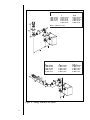
MAKE SURE THE FLAMES
ARE STEADYNOT
LIFTING OR FLOATING.
Figure 31. Burner Flame Patterns
STANDING PILOT
3/8" (10 mm)
NOTE: FLAMES
TOO CLOSE TO
THE CERAMIC
INSULATORS CAN
CAUSE NUISANCE
LOCKOUTS AND
ELECTRODE
FAILURE.
DSI IGNITION
CERAMIC
INSULATOR
3/16" (5 mm)
Figure 32. Pilot/Ignitor Flame Patterns
33
IGNITOR
1/2 (13mm)
All parts listed in this INSTALLERS GUIDE may be
ordered from an authorized dealer. When requesting
service or replacement parts for your fireplace, please
provide the model number and the serial number.
Standing Pilot Only
PART
PART DESCRIPTION
PART NUMBER
Valve LP
SRV60-523
Valve NG
SRV60-522
Piezo Ignitor
SRV60–513
Thermopile
SRV60–512
Thermocouple
SRV446-511
Pilot Orifice LP
Pilot Orifice NG
SRV446–517
SRV446–505
Pilot Assembly LP
SRV446-511A
Pilot Assembly NG
SRV446-510A
Pilot Tube
SRV446-301
Burner Tube
SRV60-307
5
Replacement
Parts and
Accessories
34
DSI Ignition Only
PART
35
PART DESCRIPTION
PART NUMBER
DSI Valve LP
DSI Valve NG
SRV77–501
SRV77–500
Transformer
SRV60–599
DSI Module
SRV420–592
Electrode
SRV77–591
Burner Tube
SRV422-302
Both Standing Pilot and DSI Ignition
PART
PART DESCRIPTION
PART NUMBER
High Temperature Limit Switch
SRV92–531
Burner
- 6000GDVFL & 6000XLS NG
SRV446-176A
- 6000 GDVFL & 6000XLS LP
SRV446-175A
Burner Orifice
- 6000XLS LP
- 6000XLS NG
SRV414–800
SRV446–801
- 6000GDVFL NG
SRV57–800
- 6000GDVFL LP
SRV57–801
On/Off Rocker Switch
SRV60–525A
Glass Door Assembly
- 6000GDVFL
- 6000XLS
Glass Clip Assembly
GLA–6FL
GLA-6XLS
SRV60–135AX
Wing Nut
SRV60–872
Glass Spring Fastener
SRV79-001A
GLASS SPECIFICATIONS:
6000GDVFL:
6000XLS:
20 X 34
20 X 34
TEMPERED
CERAMIC
36
Both Standing Pilot and DSI Ignition (Cont.)
PART
PART DESCRIPTION
Trim Door
-6000 MODELS (MESH)
-6000 MODELS (NO MESH)
Log Set Assembly
-6000GDVFL
-6000XLS
PART NUMBER
DF-6000
DF-36
LOGS-6FL
LOGS-CAMP
Accessories
PAR T
PAR T D E S C R IP T ION
Fa n K i t
Re mo te Co ntro l
Wa ll S wi tch K i t
- Off Whi te
- Whi te
37
PAR T N U M B E R
GFK -160A
RC-S TAT
S MA RT-S TAT
RC-MLT
WS K -21
WS K -21-W