1
3/3/6HULHV
8VHU0DQXDO
Preface
Thank you very much for purchasing a Pro-face PL-6930/PL-7930 Unit, hereafter referred to as PL. PL is a general-purpose computer for Factory Automation (FA), which accomplished high performance and the newest architecture with low
cost. Before using the PL, read this manual thoroughly to familiarize yourself with the PL’s operation procedures and
functions.
NOTICE
1.
Copying this manual’s contents, either in whole or in part, is prohibited without the express permission of Digital
Electronics Corporation, Japan.
2.
The information contained in this manual is subject to change without notice.
3.
If you find any errors or omissions in this document, please contact Digital Electronics Corporation to report your
findings.
4.
Regardless of Clause 3 above, Digital Electronics Corporation shall not be held responsible for any damage,
losses or third-party damage resulting from the use of this product.
Product names used in this manual are the trademarks / registered trademarks of their respective owners.
© 2006 Digital Electronics Corporation. All rights reserved.
1
Essential Safety Precautions
All safety-related procedures stated in this document must be followed to operate the PL correctly and safely. Be sure to
read this and any related documents thoroughly to understand the correct operation and functions of the PL unit.
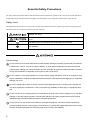
Safety Icons
Throughout this manual, these icons provide essential safety information for PL operation procedures requiring special
attention. These icons indicate the following levels of danger:
Indicates situations where severe bodily injury, death or major equipment
damage can occur.
Indicates situations where slight bodily injury or minor equipment damage can
occur.
Indicates actions or procedures that should NOT be performed.
Indicates actions or procedures that MUST be performed to ensure correct
unit operation.
System Design
Do not create PL touch panel switches that could possibly endanger the safety of personnel or equipment.
A malfunction of the PL unit, its I/O unit(s), cable(s), or other related equipment can cause unexpected
output signals, leading to a serious accident. Be sure to design all important machine operation switches
so they are operated via a separate control system, and not via the PL.
Do not create PL touch panel switches to control machine safety operations, such as an emergency stop
switch. Install these switches as separate hardware switches, otherwise severe bodily injury or equipment
damage can occur.
Be sure to design your system so that a communication fault between the PL and its host controller will
not cause equipment to malfunction. This is to prevent any possibility of bodily injury or equipment damage.
Do not use the PL as a warning device for critical alarms that can cause serious operator injury, machine
damage or can halt system operation. Critical alarm indicators and their control/activator units must be
designed using stand-alone hardware and/or mechanical interlocks.
Do not use the PL with aircraft control devices, aerospace equipment, central trunk data transmission
(communication) devices, nuclear power control devices, or medical life support equipment, due to these
devices’ inherent requirements of extremely high levels of safety and reliability.
2
Be sure to use redundant and/or fail-safe system designs to ensure adequate levels of system reliability
and safety when using the PL with transportation vehicles (trains, cars and ships), disaster and crime prevention devices, various types of safety equipment, non-life support related medical devices, and other
similar equipment.
After the PL unit’s backlight burns out the touch panel is still active, unlike the PL unit’s “Standby Mode”. If
the operator fails to notice that the backlight is burned out and touches the panel, a potentially dangerous
machine operation error can occur. Therefore, do not create PL unit touch panel switches that may cause
injury and/or equipment damage.
If your PL unit’s backlight suddenly turns OFF, use the following steps to determine if the backlight is actually burned out.
1) If the PL unit’s “Backlight Control” is not set and the screen has gone blank, your backlight is burned
out.
2) If the PL unit’s “Backlight Control” is set to Standby Mode and the screen has gone blank, and touching
the screen or performing another input operation does not cause the display to reappear, your backlight
is burned out.
Handling
Do not modify the PL unit. Doing so may cause a fire or an electric shock.
Do not operate the PL in an environment where flammable gases are present, since it may cause an
explosion.
Wiring
To prevent an electric shock be sure to disconnect your PL unit’s power cord from the power supply before
wiring the PL.
Do not use voltage beyond the PL unit’s specified range. Doing so may cause a fire or an electric shock.
Maintenance
Do not connect or disconnect Host and PL unit communication cables while the PL is turned ON.
The PL uses a lithium battery for backing up its internal clock data and the battery may explode if it is
replaced incorrectly. When replacement is required, use a Pro-face-designated product.
SEE
8.6 Replacing the Internal Battery (page8-15)
3
Installation
Be sure all cable connectors are securely attached to the PL unit. A loose connection may cause incorrect
input or output signals.
Wiring
Be sure to ground the PL unit’s FG wire separately from other equipment FG lines. Also, be sure to use a
grounding resistance of 100Ω or less and a 2mm2 or thicker wire, or your country's applicable standard.
Otherwise, electric shock or malfunctions may result.
Be sure to use only the designated torque to tighten the PL unit’s terminal block screws. If these screws
are not tightened firmly, it may cause a short-circuit, fire or incorrect unit operation.
Be sure that metal particles and wiring debris do not fall inside the PL unit. They can cause a fire,
malfunction or incorrect unit operation.
Maintenance
Do not reset or turn the PL OFF, or insert or remove the hard disk or the CF Card while the PL unit’s CF
Card is being accessed. Otherwise, the data in the hard disk or CF Card may be damaged or lost.
Unit Disposal
When the product is disposed of, it should be done so according to your country’s regulations for similar
types of industrial waste.
General Safety Precautions
Do not press on the PL unit’s display with excessive force or with a hard object, since it can damage the
display. Also, do not press on the touch panel with a pointed object, such as the tip of a mechanical pencil
or a screwdriver, since doing so can damage the touch panel.
Do not install the PL where the ambient temperature exceeds the specified range. Doing so may cause a
unit malfunction.
To prevent abnormally high temperatures from occurring inside the PL, do not restrict or block the PL
unit’s rear-face ventilation slots.
Do not operate the PL in areas where large, sudden temperature changes can occur. These changes can
cause condensation to form inside the PL, possibly causing it to malfunction.
Do not allow water, liquids or metal fragments to enter inside the PL unit’s case, since they can cause
either a malfunction or an electric shock. For use in Pollution Degree 2 environment.
Do not operate or store the PL in locations where it can be exposed to direct sunlight, high temperatures,
excessive dust, moisture or vibration.
4
Do not operate or store the PL where chemicals evaporate, or where chemicals are present in the air.
Corrosive chemicals
: Acids, alkalines, liquids containing salt
Flammable chemicals
: Organic Solvents
Do not use paint thinner or organic solvents to remove dirt or oil from the PL unit’s surface. Instead, use a
soft cloth moistened with a diluted neutral detergent.
Do not use or store the PL in areas with direct sunlight, since the sun's ultraviolet rays may cause the
LCD’s quality to deteriorate.
Do not store the PL in an area where the temperature is lower than that recommended in the PL unit’s
specifications. Doing so may cause the LCD display’s liquid to congeal, which can damage the LCD. Also,
if the storage area’s temperature becomes higher than the specified level, the LCD’s liquid may become
isotropic, causing irreversible damage to the LCD. Therefore, only store the PL in areas where temperatures are within the PL unit’s specifications.
After turning OFF the PL, be sure to wait a few seconds before turning it ON again. The PL may not operate correctly if it is restarted too quickly.
Due to the possibility of unexpected accidents, be sure to back up the PL unit’s data regularly.
LCD Panel Usage Precautions
• The LCD panel’s liquid contains an irritant. If the panel is damaged and any of this liquid contacts your skin,
immediately rinse the area with running water for at least 15 minutes. If the liquid gets in your eyes, immediately rinse
your eyes with running water for at least 15 minutes and consult a doctor.
• The PL unit’s LCD screen may show unevenness in the brightness of certain images or at some contrast settings. This
is an LCD characteristic and not a product defect.
• The PL unit’s LCD screen pixels may contain minute black and white-colored spots. This is an LCD characteristic and
not a product defect.
• The color displayed on the PL unit’s LCD screen may appear different when seen from outside the specified viewing
angle. This is an LCD characteristic and not a product defect.
• When the same image is displayed on the PL unit’s screen for a long period, an afterimage may appear when the image
is changed. If this happens, turn off the PL, wait 10 seconds and then restart the unit. This is an LCD characteristic and
not a product defect.
• To prevent an afterimage:
• Set the PL unit’s display OFF feature when you plan to display the same screen image for a long period of time.
• Change the screen image periodically and try to not display the same image for a long period of time.
5
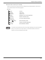
Information Symbols
This manual uses the following icons:
Indicates a warning or a product limitation. Be sure to follow the instructions
given with this icon to ensure the safe operation of the PL.
Contains additional or useful information.
(1) (2)
*1
SEE
PL-X930 Series
Indicates steps used to accomplish a given task.
Be sure to follow these steps in the order they are written.
Indicates useful or important supplemental information.
Indicates pages containing related information.
Indicates a generic name for the products of PL-6930 and PL-7930.
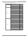
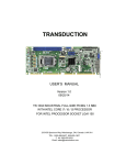
The Diagram for the PL Series Models
The type
PL∗93∗-T4∗
A
B CDE
6
PL-6930 Series (12 inch type)
7
PL-7930 Series(15 inch type)
0
4 Slot Type
1
2 Slot Type
C
T
TFT color LCD Type
D
4
CE Marking, UL/c-UL Approval
1
Model without FAN
CPU: CeleronM 1.3GHz
2
Model attached FAN
CPU: PentiumM 1.6GHz, or
CeleronM 1.3GHz
(Embedded Optional Items)
A
B
E
6
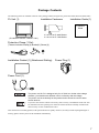
Package Contents
The following items are included in the PL unit’s package. Before using the PL, please check that all items listed below.
PL Unit (1)
Installation Fasteners
Installation Guide (1)
Installation
Guide
(PL-6930/PL-6931/PL-7930/PL-7931)
4 / set x 2 for PL-6930 Series
4 / set x 3 for PL-7930 Series
Protective Clamp (1 Set)
(The set includes Clamp(1),Bracket(1),Screw(1))
Installation Gasket (1) (Attachment Setting)
Power Plug (1)
Power Cord (1)
• The power cord for PL is designed only for AC100V use. Under other voltage
situation, you should use a different cord in conformity with the voltage.
• The power cord is exclusively for this product and it cannot be used for other
electric devices.
• If your PL unit contains a built-in accessory, that accessory’s Installation Guide will also
be included in the PL’s packing box. Please check that all items normally included with
that accessory are also included in this box.
This unit has been carefully packed, with special attention to quality. However, should you find anything damaged or
missing, please contact your local PL distributor immediately.
7
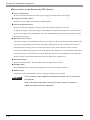
Main Features
The PL-6930/PL-7930 series displays are equipped with the following features.
• The Latest, High-Performance Architecture
Designed around the Pentium®M (1.6GMHz) or Celeron®M (1.3GMHz) CPU, the PL utilizes the type of high
performance architecture that offers you superior compatibility. Add to this unrivalled support of the Windows®
XP and other widely used operating systems.
• High Expendability
PL supports expansion PCI/ISA bus. For the 4 slot type (PL-6930 and PL-7930) three slots are available for both
PCI bus and ISA bus. For the 2 slot type (PL-6931 and PL-7931) one slot is available for a PCI bus and two slots
are available for ISA bus.
• Bright LCD with a Wide Viewing Angle
The PL’s large TFT LCD display offers excellent visibility and brightness.
• Pro-face’s top of the line TFT color LCD allows you to create detailed and powerful visual
images, with excellent brightness, a wide viewing angle, and a display capable of 64K colors.
• High Resolution, Analog-Resistance-Film Touch Panel
Standard equipment with the PL is a high resolution 1024 x 1024 touch panel, and the mouse emulation utility
provides mouse-like functionality and pointer control.
• Easy Front Panel Installation
The PL is designed to be installed easily into the front of any panel or device. It is also rugged enough for use in
harsh, industrial environments, such as those found in the factory automation industries and provides protection
equivalent to the IP65f standard.
• Front-Access Port execution control function
This function can control some accesses from the access ports (USB port or reset switch) of the front face. This
operation prevents your important data from unwilling accesses, which may harm or destroy.
SEE
1.1.2 Front Access Port Execution Control (page1-4)
• Supporting USB2.0
USB2.0 supports USB High-speed devices.
8
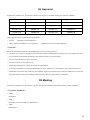
UL Approval
PL6930-T4*, PL6931-T4*, PL7930-T4*, PL7931-T4* are UL/c-UL listed products (UL File No. E220851)
Product Model No.
UL Registration Model No.
Product Model No.
UL Registration Model No.
PL6930-T41
3480901-01
PL7930-T41
3480901-05
PL6930-T42
3480901-02
PL7930-T42
3480901-06
PL6931-T41
3480901-03
PL7931-T41
3480901-07
PL6931-T42
3480901-04
PL7931-T42
3480901-08
Those products conform to the following standards:
• UL508
Industrial Control Equipment
• CSA-C22.2 No.142-M1987 (c-UL Approval)
Standard for Process Control Equipment
<Cautions>
Be aware of the following items when building the PL into an end-use product:
• The PL unit’s rear face is not approved as an enclosure. When building the PL unit into an end-use product, be sure to
use an enclosure that satisfies standards as the end-use product’s overall enclosure.
• For use on flat surface of a type 1 Enclosure.
• The PL unit must be used indoors only.
• Install and operate the PL with its front panel facing outwards.
• If the PL is mounted so as to cool itself naturally, be sure to install it in a vertical panel. Also, insure that the PL is
mounted at least 50 mm away from any other adjacent structures or machine parts. If these conditions are not met, the
heat generated by the PL unit's internal components may cause it to fail to meet UL standards.
CE Marking
PL6930-T4*, PL6931-T4*, PL7930-T4*, PL7931-T4* are CE marked products that conform to EMC compliant.
<Compliant Standards>
• Saftey
EN60950-1
• EMI
EN55011 ClassA, EN61000-3-2, EN61000-3-3
• EMS
EN61000-6-2
9
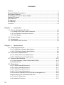
Contents
Preface...................................................................................................................... 1
Essential Safety Precautions ................................................................................... 2
Information Symbols ................................................................................................ 6
The Diagram for the PL Series Models .................................................................... 6
Package Contents .................................................................................................... 7
Main Features .......................................................................................................... 8
UL Approval ............................................................................................................. 9
CE Marking .............................................................................................................. 9
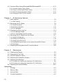
Contents.................................................................................................................. 10
Chapter 1
Introduction
1.1 Prior to Operating the PL Unit......................................................................... 1-2
1.1.1 Setting Up the Touch Panel Connection ...............................................................1-3
1.1.2 Front Access Port Execution Control ....................................................................1-4
1.1.3 Power Supply........................................................................................................1-5
1.2 System Design................................................................................................ 1-6
1.3 Accessories .................................................................................................... 1-7
1.4 Part Names and Functions ............................................................................. 1-9
Chapter 2
Specifications
2.1 General Specifications .................................................................................... 2-2
2.1.1 PL-6930 Series General Specifications ................................................................2-2
2.1.2 PL-7930 Series General Specifications ................................................................2-4
2.2 Performance Specifications ............................................................................ 2-6
2.2.1 PL-6930 Performance Specifications....................................................................2-6
2.2.2 PL-7930 Performance Specifications....................................................................2-9
2.3 Interface Specifications................................................................................. 2-12
2.3.1 Serial Interfaces (COM1/COM2/COM3/COM4) ..................................................2-12
2.3.2 RAS Interface......................................................................................................2-14
2.4 Dimensions ................................................................................................... 2-16
2.4.1 PL-6930 External Dimensions ............................................................................2-16
2.4.2 PL-6931 External Dimensions ............................................................................2-17
2.4.3 PL-7930 External Dimensions ............................................................................2-18
2.4.4 PL-7931 External Dimensions ............................................................................2-19
2.4.5 Dimensions attached RS-232C/RS-485 exchangeable unit ...............................2-20
2.4.6 Dimensions with a full-sized board cover............................................................2-22
2.4.7 Panel Cut Dimensions ........................................................................................2-24
2.4.8 Installation Fasteners..........................................................................................2-25
10
Chapter 3
Peripheral Device Installation
3.1 Installing optional units / expansion boards .................................................... 3-2
3.1.1 Uninstalling the Rear Maintenance Cover ............................................................3-2
3.1.2 Installing the Main Memory ...................................................................................3-5
3.1.3 Uninstalling / Installing HDD units / CF card units.................................................3-6
3.1.4 Installing the Expansion board (PCI/ISA)..............................................................3-8
3.1.5 Connecting a CD-ROM drive unit .........................................................................3-9
3.2 Installing / Uninstalling PCMCIA Cards......................................................... 3-15
3.3 Installing USB Cable Clamp.......................................................................... 3-16
Chapter 4
Installation and Wiring
4.1 Installing the PL unit........................................................................................ 4-2
4.1.1 Installation Procedures .........................................................................................4-2
4.2 Wiring.............................................................................................................. 4-7
4.2.1 Connecting the Power cord ..................................................................................4-7
4.2.2 Connecting the Power Supply ............................................................................4-10
4.2.3 Grounding Precaution ......................................................................................... 4-11
4.2.4 I/O Signal Line Placement Precaution ................................................................ 4-11
Chapter 5
System Setup
5.1 Setup Procedures ........................................................................................... 5-2
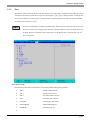
5.2 System Parameters ........................................................................................ 5-3
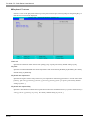
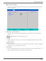
5.2.1 Main ......................................................................................................................5-3
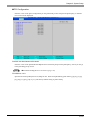
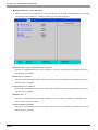
5.2.2 Advanced ..............................................................................................................5-6
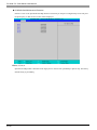
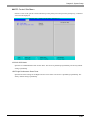
5.2.3 Intel .....................................................................................................................5-19
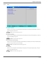
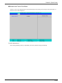
5.2.4 Security ...............................................................................................................5-30
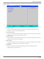
5.2.5 Boot ....................................................................................................................5-31
5.2.6 Exit ......................................................................................................................5-33
Chapter 6
Setting Up Software
6.1 Setting Up Your PL Unit .................................................................................. 6-2
6.1.1 Setting Up an HDD with no Pre-installed OS........................................................6-2
6.1.2 Setting Up an HDD with Pre-installed OS.............................................................6-4
6.2 Installing Drivers ............................................................................................. 6-6
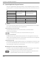
6.3 Special Application Program Features............................................................ 6-8
6.3.1 Uninstalling PL-X930 Driver and Utility ...............................................................6-10
11
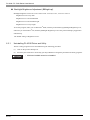
6.4 Cautions When Using Windows®2000/Windows®XP...................................6-11
6.4.1 Automatic System Log-on Setup ........................................................................ 6-11
6.4.2 Using an Uninterrupted Power Supply................................................................ 6-11
6.4.3 When Changing the System Design ...................................................................6-12
6.4.4 Changing to the NTFS File System ....................................................................6-12
Chapter 7
PL Monitoring Features
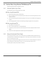
7.1 RAS Features ................................................................................................. 7-2
7.1.1 RAS Features .......................................................................................................7-2
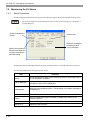
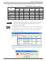
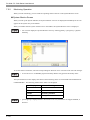
7.2 Monitoring the PL Status................................................................................. 7-8
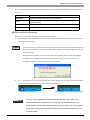
7.2.1 Setup Procedures .................................................................................................7-8
7.2.2 Monitoring Operation ..........................................................................................7-10
7.2.3 Error Messages...................................................................................................7-12
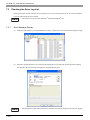
7.3 Checking the Error Log List .......................................................................... 7-14
7.3.1 Error Message Display........................................................................................7-14
7.3.2 Error Type/Location and Error Action..................................................................7-15
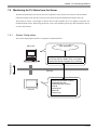
7.4 Monitoring the PL Status from the Server..................................................... 7-17
7.4.1 System Configuration..........................................................................................7-17
7.4.2 Setting Up the Client PL......................................................................................7-18
7.4.3 Setting Up the Server PC....................................................................................7-19
7.4.4 Reading/Writing the Status of the System Monitor/RAS Feature........................7-20
7.4.5 Restrictions .........................................................................................................7-24
7.5 Restarting/Shutting down the PL from the Server ........................................ 7-26
Chapter 8
Maintenance
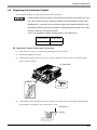
8.1 Cleaning the Display....................................................................................... 8-2
8.2 Cleaning the Fan Filter ................................................................................... 8-3
8.3 Periodic Inspection Items................................................................................ 8-4
8.4 Replacing the Installation Gasket ................................................................... 8-5
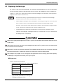
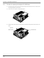
8.5 Replacing the Backlight .................................................................................. 8-7
8.5.1 Procedure for replacing the backlight of PL-6930 Series......................................8-8
8.5.2 Procedure for replacing the backlight of PL-7930 Series.................................... 8-11
8.6 Replacing the Internal Battery ...................................................................... 8-15
Appendices
12
1
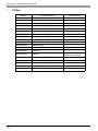
I/O Map ........................................................................................................... A-2
2
Memory Map................................................................................................... A-3
3
Interrupt Map .................................................................................................. A-4
4
Consent Agreement........................................................................................ A-5
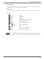
1
Introduction
1. Prior to Operating the PL Unit
2. System Design
3. Accessories
4. Part Names and Functions
This chapter describes peripheral devices that can be connected to PL Series units along with the name and
functions of each part.
1-1
PL-6930 / PL-7930 Series User Manual
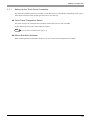
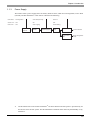
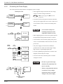
1.1 Prior to Operating the PL Unit
The following procedures are prior to use the PL unit.
Connect Peripheral Devices
Connect the display unit and any optional devices.
SEE
Connect Power
1.2 System Design (page1-6)/1.3
Accessories (page1-7)
Connect the PL unit's power cord to AC Interconnection and turn the power switch ON.
SEE
4.2 Wiring (page4-7)
Configure the PL unit's BIOS.
Set Up the System
SEE
5.1 Setup Procedures (page5-2)
[When PL has no preinstalled OS]
[When PL has preinstalled OS]
Setup an OS for the PL.
Install a commercial
OS in your PL. For
how to setup the OS,
refer to the manual
provided with the
product.
Install an OS
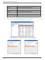
Download and install the necessary divers and utility software
SEE
6.1.1 Setting Up an HDD with no
Pre-installed OS (page6-2)
Visit the download page at the Otasuke Pro! site.
URL http://www.pro-face.com/otasuke/
Setup the pre-installed PL.
Install Required Software
Install the PL Unit
SEE
6.1.2 Setting Up an HDD with Preinstalled OS (page6-4)
Install all required software. For software installation instructions, refer to the manual provided
with that product.
• After hardware setup is completed, the OS (Windows®2000, Windows®XP) must
be used to create partitions and format (initialize) the HDD before any data or
applications can be saved to the hard disk drive. For details concerning these
procedures, refer to the OS manufacturer's instruction manual.
• Whenever you turn the PL unit's power OFF, wait until the internal HDD stops
spinning (approximately 5 seconds) before turning the power ON again.
• The PL’s hard disk is designed for use with the Windows®2000, Windows®XP.
This driver software can’t be applied to other operating systems.
1-2
Chapter 1 Introduction
1.1.1
Setting Up the Touch Panel Connection
The connection method used can be via either a serial (RS-232C) or USB interface. Depending on the type of
Touch Panel connection used, the OS types that can be used will vary.
Touch Panel Changeover Switch
The switch changes the switch placed on the board inside of the unit to a state of COM4.
See the following for the place of the chageover switch.
SEE
1.4 Part Names and Functions (page1-9)
Mouse Emulation Software
When installing the Mouse Emulation Software, be sure to select Serial communication (COM4).
1-3
PL-6930 / PL-7930 Series User Manual
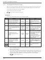
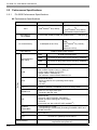
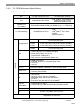
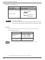
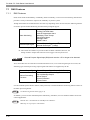
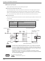
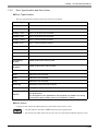
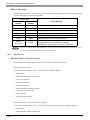
1.1.2
Front Access Port Execution Control
When you open the front maintenance hatch of the front unit, there are USB ports and a reset switch. If you
want to prevent unwilling or unintentional accesses, change the DipSW settings not to be executed some
accesses from reset from the front side or the USB ports.
See the following for the place of the DipSW.
SEE
1.4 Part Names and Functions (page1-9)
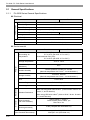
DipSW
For the factory default settings; SW No.1 is ON, the others are OFF.
SW No.
Meaning
ON
OFF
Notes
Enabled
Disabled
The front USB port is available
when the SW is ON. It is
unavailable when the SW is
OFF.
Reserved
Do not change the initial
setting.
1
Sets up an enabled/disabled
state for the front USB*1 port
execution control function
2
Used for the system
Reserved
3
Sets up an output of the USB
control signals(RAS DOUT2) if
needed.
Output
mode for
UPS
Shutdown
4
Implements the logical
inversion operation for RAS
output
5
Set up an enabled/disabled
state for the port execution
control function of the front
reset switch.
Normal
Close
Disabled
Normal
Output
RAS DOUT2 is the only for the
UPS control output when the
SW is ON. In that case, RAS
OUT2 cannot be used for
normal output.
Normal
Open
RAS output is a CLOSE state
when the SW and the system
is ON. When the SW is OFF, it
is the opposite.
The RAS Output keeps
Normal OPEN when the Soft
OFF*2 state occurs or the
power turns OFF.
Enabled
The hardware switch is
unavailable when the SW is
ON. But, it is available to enter
switch from the Soft OFF*2
state.
Reserved
Do not change the initial
setting.
6
7
Used for the system.
Reserved
8
*1
The Setting up an enabled/Disabled state for USB port execution control function is available for only Windows®2000 and Windows®XP. Make sure to disable the function of the setting when other OS used.
*2
The Soft OFF refers to the state that Windows® has been shut down and the power is provided only for the electric circuit to boot system. This Soft OFF State is different from what
is System Standby set by Windows®. For the state of Soft OFF, see the following.
SEE
1-4
1.1.3 Power Supply (page1-5)
Chapter 1 Introduction
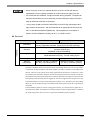
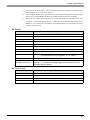
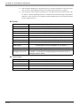
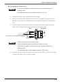
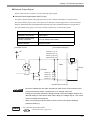
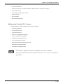
1.1.3
Power Supply
About states of PL’s power supply, there are three(3) kinds of states, which are No Energization, Active State
(Normal), and Soft OFF State*1. Each state is outlined in the following.
Power State : No Energization
Active State (Normal)
Soft OFF
Screen of PL : OFF
ON
OFF
Power LED
Green Lighting
Green Blinking
: OFF
PL’s
power On
PL’s system
activated
Shut down by
Windows program
System
Stop
Reset Switch ON
Power Switch OFF,
Remove Power
Cable
*1
for Normal State
for No Energization
State
The Soft OFF refers to the state that Windows® has been shut down and the power is provided only for
the electric circuit to boot system. This Soft OFF State is different from what is System Standby set by
Windows®.
1-5
PL-6930 / PL-7930 Series User Manual
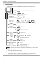
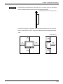
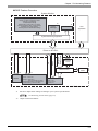
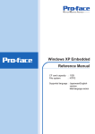
1.2 System Design
Side of PL unit
Back of PL unit
Front of PL unit
The following diagram illustrates the standard range of items that can be connected to the unit.
USB 2.0 or 1.1 Compatible Peripherals (commercial type)
USB I/F x 1
USB I/F x 2
USB 2.0 or 1.1 Compatible Peripherals
USB Keyboard on the narkef
SOUND
(LINE IN.MIC.SPK)
Pin- jack Cable
(commercial type)
Sound Devices such as Speaker
Major
Network
LAN I/F x 2
(100/10BASE-T)
Hub
Twisted Pair Cable
(commercial type) (commercial type)
PCMCIA
/CARD BUS *3 x 1
Graphic Operation Panel for GP series
(Commercial or Conventional products)
Commercial Item
Primary (HDD0)
HDD/CF Card
Unit I/F x 2
HDD Unit *1
Secondary (HDD1)
HDD Unit or CF Card Unit *1 *2
Secondary
IDE I/F
RS232C I/F COM1.2.3.4
(D-sub 9pin)
CD-ROM Drive Unit *1
Serial Cable
(commercial type)
Peripherals
(commercial type)
RS-232C/RS-485 Converting Unit *1
(Available only for COM2 / COM3)
RAS I/F
(D-sub 25pin)
MEMORY SLOTx1
200pin SODIMM
RAS Cable
(Produces by users)
DIM Module *1
ISA board (commercial type)
PCI/ISA SLOT
(4SLOT type :3 PORT,2SLOT type :1 PORT)
PCI board (commercial type)
(4SLOT type :3 PORT,2SLOT type :1 PORT)
• This diagram shows only the PL's internal layout and connectable devices. The user's actual
design may differ.
*1
The Pro-face’s optional devices used with PL.
*2
When using the HDD unit with the CD-ROM drive unit at the same time, be sure to set the HDD unit’s
setting as Master. [Chapter 3 Uninstalling / Installing HDD units / CF card units (page3-6).]
*3
1-6
The CARD BUS doesn’t include functions of ZOOMED VIDEO, SOUND.
Chapter 1 Introduction
1.3 Accessories
All accessories listed here are produced by Digital Electronics Corporation.
Optional Items
Product Name
Model No.
Description
PSA-DDR512
DIM module 512M Bytes
PSA-DDR1G
DIM module
CD-ROM Drive Unit
PSS-CD01
IDE (ATAPI) compatible CD-ROM drive unit
(Connection cable is included with CDROM unit)
CF Card Unit
PL-CF200
Designed exclusively for 5V type cards.
Hard Disk Unit
PL-HD240
HDD Unit mounted a Type 2.5 Hard Disk
The capacity is 40G byte and it doesn’t
include OS.
PL-FC200
Used when ISA full-sized expansion board
is used. (Used only with PL-6931/PL-7931.)
PL-FC210
Used when ISA full-sized expansion board
is used. (Used only with PL-6930/PL-7930)
RS-232C/RS-485
Converting Unit
PL-RC500
RS232C - a converting unit for
RS485.When used, it should be placed on
COM2 or COM3.
Screen Protection Sheet
PL-CS100
Disposable sheet that protects the PL unit’s
screen and prevents from dust.
(5 sheets/set) (Hard type)
CA3-CFCALL/128MB-0*
TYPE 1 128M byte
CA3-CFCALL/256MB-0*
TYPE 1 256M byte
CA3-CFCALL/512MB-0*
TYPE 1 512M byte
CA6-CFCALL/1GB-01
TYPE 1
DIM Module Memory
1G Bytes
Full Sized Board Cover
CF Card
1G byte
• Since the PL unit's hard disk drive (HDD) is a consumable item, i.e. it has a
limited lifetime, be sure to back up its data regularly and prepare a spare HDD
unit.
• The Hard Disk lifetime given here may be reduced due to unforeseen
environmental factors.The disk will be available until either of the following
conditions comes first. One is it spends 20,000 energization hours, the other is it
reaches 5 years. Those conditions are under at a condition of the surrounding
temperature 20 °C. The use condition and its environment will affect the lifetime
span.
1-7
PL-6930 / PL-7930 Series User Manual
Maintenance Items
Product Name
Installation Fastener
Model No.
CA3-ATFALL-01
PL6900-WP00
(PL-6930 Series)
Installation Gasket
PL7900-WP00
(PL-7930 Series)
Description
Used to install the PL into a solid panel.
(4/set x 2 for PL-6930 Series, 4/set x 3 for
PL-7930 Series)
Provides dust and moisture resistance
when PL is installed into a solid panel.
CA3-BLU12-01
(PL-6930 Series)
Replacement Backlight
Replacement backlight
CA3-BLU15-01
(PL-7930 Series)
Commercially Available Items
The PL-6930 and PL-7930 Series units can all use commercially available expansion boards (PCI/ISA
compatible) as well as a standard keyboard, mouse, printer, etc. When using a USB cable, the PL-6930 and
PL-7930 Series units can also use USB compatible devices. However, among the commercially available
USB devices, not all will be compatible with the PL unit.
• Be sure to use only DIM modules manufactured by Digital. Installing other DIM modules may
result in either damage to or failure of the PL, and will void your warranty.
• When using USB type devices, be sure they are USB compatible, and be sure to read that
device's installation guide prior to connecting it to the PL.
1-8
Chapter 1 Introduction
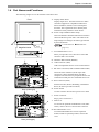
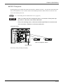
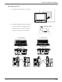
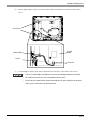
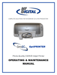
1.4 Part Names and Functions
The following images are of a PL-6930/PL-7930 Series unit.
A: Display/Touch Panel
Front
Display output area. The built-in SVGA or XGA
controller supports PC compatible architecture.
Mouse emulation, which is one of Touch panel
functions, has a significant role to build system
architecture easily without a mouse device.
A
B: Power Lamp LED/RAS Status Lamp
This LED indicates both the RAS monitor feature's
status and the PL's power status. The status of the
lamp changes according to the alarm type detected
by the RAS feature.
B
SEE
C
Magnified inside
7.1 RAS Features LED Indicator
(page7-5)
C: Front Maintenance Cover
D
When you open this cover, there are a front USB
connector and a reset switch.
E
D: Hardware Reset Switch (RESET)
F
G
E: USB Connector (USB)
USB 2.0 compatible devices can be connected here.
F: RS-232C Connector(COM1/COM2COM3/COM4)
K
H
These RS-232C interfaces (D-sub 9 pin male
connectors), allow communication with other
computers and connection to peripheral devices.The
COM2 and COM3 ports are switchable for RI/+5V.
G: RAS connector (RAS)
I
J
Interface for DIN, DOUT, Watchdog, and Remote
Reset. (D-sub 25 pin male connector)
H: Power Switch
Rear (4 slot type)
F
G
Use this switch to turn the PL's power ON or OFF.
I: Power Connector
Plug a power cord in here.
K
J: IDE Cover
To connect the optional CD-ROM drive unit (PSSCD01), remove this cover and use this connector.
H
I
J
K: Rear Maintenance Cover
To install DIM module and various expansion
boards, which are optional products, remove this
cover.
Rear (2 slot type)
1-9
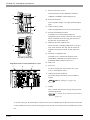
PL-6930 / PL-7930 Series User Manual
L: Ethernet Connector (LAN)
Network Interface (meets IEEE802.3 standard /
L
O
M
10BASE-T/100BASE-TX autochangeover).
M: Sound I/O Interface
Used to Speaker output, Line input and Microphone
input.
N
P
Q
Right Side (4 slot type)
N: USB Connector (USB)
USB 2.0 compatible devices can be connected here.
O: PCI/ISA board Expansion Slot
Available to use commercial PCI/ISA bus
compatible boards. From the front face side, the slot
names are dubbed as the first slot, the second slot,
the third slot, and the forth slot.*1
P: HDD/CF card unit expansion slot
R
These slots aim at installing HDD units or CF card
units. From the front face side, the slot names are
dubbed as the expansion slot0, and the expansion
slot1.
S
Q: PCMCIA / CARD BUS slot
Left Side (4 slot type)
Magnified inside of Rear Maintenance Cover
T
V
U
Available to use a commercial PCMCIA card /
CARD BUS (CARD BUS excepts functions of
ZOOMED VIDEO, SOUND, however).
R: Half Cover
S: Fan Cover
For the 2 slot type (PL-6931 and PL-7931), fan
cover is in the bottom of unit.
T: Changeover Switch for RI/5V
The switch changes the RI/5V state of COM2 or
COM3.
SEE
RI/5V Changeover (page2-13)
U: DipSW
X
W
This is a mask switch for PL setting, which prevents
accidental operation.
SEE
1.1.2 Front Access Port Execution Control
(page1-4)
*1 For the 4 slot type (PL-6930 and PL-7930), the first slots is available only for ISA bus and the second slot
is only available for PCI bus. For the 2 slot type (PL-6931 and PL-7931) the first slot is available only for ISA
bus.
1-10
Chapter 1 Introduction
V: Touch Panel Changeover Switch
The communication method can be changed by USB
or COM4.
SEE
1.1.1 Setting Up the Touch Panel Connection (page1-3)
W: Main Memory
X: Internal Battery
• Refer to the following to know how to uninstall the rear maintenance cover.
SEE
3.1.1 Uninstalling the Rear Maintenance Cover (page3-2)
1-11
PL-6930 / PL-7930 Series User Manual
Memo
1-12
2
Specifications
1. General Specifications
2. Performance Specifications
3. Interface Specifications
4. Dimensions
This chapter describes the general, functional and interface specifications of the PL as well as its part names
and dimensions.
2-1
PL-6930 / PL-7930 Series User Manual
2.1 General Specifications
2.1.1
PL-6930 Series General Specifications
Electrical
Power Supply
Item
PL-6930
PL-6931
Input Voltage
AC100 / 240V
Rated Voltage
AC85 to 265V
Rated Frequency
50Hz to 60Hz
Allowable Voltage Drop
Current Consumption
1cycle or less (Voltage drop interval must be 1s or more.)
150VA (max.)
130 VA (max.)
leakage current
2.0mA (max.)
In-Rush Current
30A (max.)
Voltage Endurance
AC1500V 20mA for 1 minute
Insulation Resistance
DC500V 10MΩ (min.)
Environmental
Item
Physical
Surrounding Air
Temperature
Wet-bulb temperature
(Maximum)
29°C
Ambient Humidity
10%RH (Relative Humidity) to 85%RH
(Wet bulb temperature: 29°C max. - no condensation.)
Storage Humidity
10%RH to 85%RH
(Wet bulb temperature: 29°C max. - no condensation.)
Corrosive gas
Mechanical
Model without FAN (T41) :
5°C to 40°C (No HDD : 0°C to 40°C)
Model attached FAN (T42) :
5°C to 50°C (No HDD : 0°C to 50°C)
-10°C to +60°C
Pollution Degree
Electrical
PL-6931
Storage Temperature
Dust
Vibration Resistance
Free of dust
Pollution Degree 2
Free of corrosive gas
When not using HDD units:19.6m/s² (10Hz to 25Hz / 30 min. for
each X, Y, and Z direction)
When using HDD units:4.9m/s² (10Hz to 25Hz / 30 min. for each
X, Y, and Z direction)
Noise Immunity
(via noise simulator)
Noise Voltage: 1,500Vp-p
Pulse Duration: 50ns, 500ns, 1µs
Rise Time: 1ns
Electrostatic
Discharge Immunity
4.0kV (complies with IEC61000-4-2)
Noise Immunity
(Fast Transient Burst Noise)
2-2
PL-6930
Power supply line: 2kV (IEC61000-4-4)
COM port: 1kV (IEC61000-4-4)
Chapter 2 Specifications
• When using any of the PL’s optional devices, be sure to check that device’s
specifications for any special conditions or cautions that may apply to its use.
• As a Hard Disk has a lifetime, it might be broken during operation. To prepare an
expected Hard Disk error, we recommend you take backup the data you need or
keep an alternate Hard Disk to exchange.
•
It may cause a fatal error that the Hard Disk is used in a high temperature and
high moisture environment. We recommend that an appropriate environment be
29°C in Wet-bulb temperature (Maximum). This temperature, for example, is
equal to 64%RH (Relative Humidity) at 35°C, or 44%RH at 40°C.
Structural
Item
PL-6930
PL-6931
Grounding resistance of 100 Ω, 2mm or thicker wire, or your
country’s applicable standard. (Same for FG and SG terminals)
2
Installation
Grounding
Structure
Cooling Method
Rating*1: Equivalent to IP65f (Only not using Front USB)
figuration: Built-in type
Installation method: Embedding
Model without FAN (T41) : Natural air circulation
Model attached FAN (T42) : Forced cooling by fan
Weight
Approx. 9.5kg [20.9lb]
Approx. 8.5kg [18.7lb]
External
Dimensions
W346mm [13.62in.] × H287mm
[11.30in.] × D170mm [6.69in.]
W346mm [13.62in.] × H287mm
[11.30in.] × D123mm [4.84in.]
*1
The front face of the PL unit, installed in a solid panel, has been tested using conditions equivalent to the standards shown in the specification. Even though the PL unit’s level of resistance
is equivalent to these standards, oils that should have no effect on the PL can possibly harm
the unit. This can occur in areas where either vaporized oils are present, or where low viscosity cutting oils are allowed to adhere to the unit for long periods of time. If the PL’s front face
protection sheet becomes peeled off, these conditions can lead to the ingress of oil into the PL
and separate protection measures are suggested. Also, if non-approved oils are present, it may
cause deformation or corrosion of the front panel’s plastic cover. Therefore, prior to installing
the PL be sure to confirm the type of conditions that will be present in the PL’s operating environment.
If the installation gasket is used for a long period of time, or if the unit and its gasket are removed from the panel, the original level of the protection cannot be guaranteed. To maintain
the original protection level, be sure to replace the installation gasket regularly.
2-3
PL-6930 / PL-7930 Series User Manual
2.1.2
PL-7930 Series General Specifications
Electrical
Power Supply
Item
PL-7930
PL-7931
Input Voltage
AC100 / 240V
Rated Voltage
AC85 to 265V
Rated Frequency
50Hz to 60Hz
Allowable Voltage Drop
Current Consumption
1cycle or less (Voltage drop interval must be 1s or more.)
150VA (max.)
130VA (max.)
leakage current
2.0mA (max.)
In-Rush Current
30A (max.)
Voltage Endurance
AC1500V 20mA for 1 minute
Insulation Resistance
DC500V 10MΩ (min.)
Environmental
Item
Physical
Surrounding Air
Temperature
Wet-bulb temperature
(Maximum)
29°C
Ambient Humidity
10%RH (Relative Humidity) to 85%RH
(Wet bulb temperature: 29°C max. - no condensation.)
Storage Humidity
10%RH to 85%RH
(Wet bulb temperature: 29°C max. - no condensation.)
Corrosive gas
Mechanical
Model without FAN (T41):
5°C to 40°C (No HDD : 0°C to 40°C)
Model attached FAN (T42):
5°C to 50°C (No HDD : 0°C to 50°C)
-10°C to +60°C
Pollution Degree
Electrical
PL-7931
Storage Temperature
Dust
Vibration Resistance
Free of dust
Pollution Degree 2
Free of corrosive gas
When not using HDD units:19.6m/s² (10Hz to 25Hz) / 30 min.
for each X, Y, and Z direction)
When using HDD units:4.9m/s² (10Hz to 25Hz) / 30 min. for
each X, Y, and Z direction)
Noise Immunity
(via noise simulator)
Noise Voltage: 1,500Vp-p
Pulse Duration: 50ns, 500ns, 1µs
Rise Time: 1ns
Electrostatic
Discharge Immunity
4.0kV (complies with IEC61000-4-2)
Noise Immunity
(Fast Transient Burst Noise)
2-4
PL-7930
Power supply line: 2kV (IEC61000-4-4)
COM port: 1kV (IEC61000-4-4)
Chapter 2 Specifications
• When using any of the PL’s optional devices, be sure to check that device’s
specifications for any special conditions or cautions that may apply to its use.
• As a Hard Disk has a lifetime, it might be broken during operation. To prepare an
expected Hard Disk error, we recommend you take backup the data you need or
keep an alternate Hard Disk to exchange.
•
It may cause a fatal error that the Hard Disk is used in a high temperature and
high moisture environment. We recommend that an appropriate environment be
29°C in Wet-bulb temperature (Maximum). This temperature, for example, is
equal to 64%RH (Relative Humidity) at 35°C, or 44%RH at 40°C.
Structural
Item
PL-7930
PL-7931
Grounding resistance of 100 Ω, 2mm or thicker wire, or your
country’s applicable standard. (Same for FG and SG terminals)
2
Installation
Grounding
Structure
Rating*1: Equivalent to IP65f (Only not using Front USB)
figuration: Built-in type
Installation method: Embedding
Cooling Method
Model without FAN (T41): Natural air circulation
Model attached FAN (T42): Forced cooling by fan
Weight
Approx. 10.5kg [23.1lb]
Approx. 9.5kg [20.9lb]
External
Dimensions
W374mm [14.72in.] × H325mm
[12.80in.] × D180mm [7.09in.]
W374mm [14.72in.] × H325mm
[12.80in.] × D134mm [5.28in.]
*1
The front face of the PL unit, installed in a solid panel, has been tested using conditions
equivalent to the standards shown in the specification. Even though the PL unit’s level of resistance is equivalent to these standards, oils that should have no effect on the PL can possibly harm the unit. This can occur in areas where either vaporized oils are present, or where
low viscosity cutting oils are allowed to adhere to the unit for long periods of time. If the
PL’s front face protection sheet becomes peeled off, these conditions can lead to the ingress
of oil into the PL and separate protection measures are suggested. Also, if non-approved oils
are present, it may cause deformation or corrosion of the front panel’s plastic cover. Therefore, prior to installing the PL be sure to confirm the type of conditions that will be present
in the PL’s operating environment.
If the installation gasket is used for a long period of time, or if the unit and its gasket are removed from the panel, the original level of the protection cannot be guaranteed. To maintain
the original protection level, be sure to replace the installation gasket regularly.
2-5
PL-6930 / PL-7930 Series User Manual
2.2 Performance Specifications
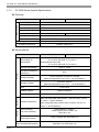
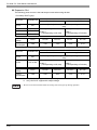
2.2.1
PL-6930 Performance Specifications
Performance Specifications
Item
CPU
Main Memory
(S.O-DIMM)
L2 Cache Memory
PL6930-T41/PL6931-T41
PL6930-T42/PL6931-T41
Intel®Celeron® M (1.3GHz)
Intel®Pentium® M (1.6GMHz),
or
Intel®Celeron® M (1.3GHz)
(Embedded Optional Items)
PC2700 DDR 256MB,512MB,1GB (DIMM socket × 1 1GB (max.))
512KB(Built in the CPU)
Video Memory
Interface
Serial (RS232C:
with FIFO)
2-6
Intel®Pentium® M (1.6GMHz) :
1MB
Intel®Celeron® M (1.3GHz) :
512KB
(Built in the CPU)
32MB to 64MB (UMA method)
COM1
D-SUB 9 pin plug MALE
COM2
D-SUB 9 pin plug MALE(5V/RI switching available)
COM3
D-SUB 9 pin plug MALE(5V/RI switching available)
COM4
D-SUB 9 pin plug MALE
USB
• USB2.0 (Support for HI SPEED 480M bps)
• The number of ports: Front (1) / Side (2)
• Power supply voltage: 5V DC ±5%
• Output current : 500mA(max.)
• The maximum communication distance: 5m
RAS
D-SUB 25PIN MALE
• 5DATA IN, 4DATA OUT (Including Reset Input)
• +12V OUT
• +5V OUT
LAN × 2
IEEE802.3 10BASE-T/100BASE-TX Auto exchange SIDE
SOUND I/O
Sound I/O, Line-input, MIC-input
• Connector: Mini Pin Jack
IDE
• Ultra ATA100
• HD SLOT 2SLOT (Primary, Secondary)
Master and Slave settings are set by HDD*1
• CD SLOT
(Concurrent use with a 2SLOT HDD available*2)
PCMCIA
/CARD BUS
• Corresponding to TypeII
• Corresponding to CARD BUS (Excluding ZOOMED VIDEO and
SOUND functions)
ISA
2SLOT/3SLOT
PCI
PCI Rev. 2.2 (33MHz) 1SLOT/3SLOT
Clock Accuracy*3
± 180 sec. / month (fudge factor by the situation at normal
temperature and power-off)
Chapter 2 Specifications
*1
*2
*3
For the setting of Master/Slave, refer to the following section; Chapter 3 Uninstalling / Installing HDD units / CF card units (page3-6)
When using the HDD SLOT1 (Expansion SLOT1) with the CD-ROM drive unit at the same
time, be sure to set the HDD/CF card unit inside the Expansion SLOT1 as Master.
The clock, RTC, built in the PL has fudge error. The range of the error will be between +300
to -300 sec. / month, depending on the PL’s conditions such as lifetime usage or temperature
difference. If you use the PL in a computer network that takes this error seriously, adjust the
clock in regular intervals.
Display
Item
Specification
Type
12 inch SVGA TFT color LCD
Resolution
Dot pitch
W800 x H600 dots (SVGA)
W0.3mm [0.01in.] x H0.3mm [0.01in.]
Effective Display Area
Color/Shade level
Backlight
W246.0mm [9.69in.] x H184.5mm [7.26in.]
260,000 colors
CFL (Compact Fluorescent Lamp) 2-color-light system
Brightness control
Contrast Adjustment
View Angles
4 levels of adjustment (Controlled by software)
None
Horizontal Direction: 120 degrees, Vertical Direction: 100 degrees
(Contrast ratio: CR is 10 or greater, or TYP value)
Display Service Life
50,000hrs.(MTTF) (Backlight display service life is not included.)
Backlight Service Life
50,000hrs. or more (at ambient temperature 25°C and continuous
operation - a period until backlight brightness decreases to 50% or
backlight starts to flicker)
Touch Panel
Item
Specification
Type
Resistive Film (analog)
Resolution
1024 x 1024
Service Life
1,000,000 times or more
Interface
USB or COM4
2-7
PL-6930 / PL-7930 Series User Manual
Expansion Slot
The following power current is the total output current when using all slots
<PL-6930(4 SLOT type)>
SLOT No.
Available Bus
Available Board Size
Standard Use
When using PL-FC210
163mm [6.42in.]x122mm [4.80in.](corresponding to Half size
only)
SLOT1
ISA
SLOT2
PCI
SLOT3
PCI or ISA
SLOT4
PCI or ISA
Output
Voltage
DC5V
DC12V
DC3.3V*1
DC-5V*2
DC-12V
4.0A
1.0A
1.5A
0.1A
0.1A
Current
Consumption
250mm[9.84in.]×122mm
[4.80in.]
(corresponding to 3Q size)
340mm [13.39in.] x 122mm
[4.80in.]
(corresponding to Full size)
<PL-6931(2 SLOT type)>
SLOT No.
Available Bus
Available Board Size
Standard Use
When using PL-FC210
163mm [6.42in.]x122mm [4.80in.](corresponding to Half size
only)
SLOT1
ISA
SLOT2
PCI or ISA
Output
Voltage
DC5V
DC12V
DC3.3V*1
DC-5V*2
DC-12V
2.0A
0.5A
0.5A
0.1A
0.1A
Current
Consumption
250mm[9.84in.]×122mm
[4.80in.]
(corresponding to 3Q size)
*1
Only PCI SLOT supports this output voltage.
*2
Only ISA SLOT supports this output voltage.
340mm [13.39in.] x 122mm
[4.80in.]
(corresponding to Full size)
• Be sure to use the PCI/ISA board concerning of the heat goes up during operation.
2-8
Chapter 2 Specifications
PL-7930 Performance Specifications
Performance Specifications
Item
PL7930-T41/PL7931-T41
CPU
Main Memory
(S.O-DIMM)
L2 Cache Memory
®Celeron®
Intel
Serial (RS232C:
with FIFO)
PL7930-T42/PL7931-T42
M (1.3GHz)
Intel®Pentium® M (1.6GMHz), or
Intel®Celeron® M (1.3GHz)
(Embedded Optional Items)
PC2700 DDR 256MB,512MB,1GB (DIMM socket × 1 1GB (max.))
Intel®Pentium® M (1.6GMHz) :
1MB
Intel®Celeron® M (1.3GHz) :
512KB
(Built in the CPU)
512KB(Built in the CPU)
Video Memory
Interface
2.2.2
32MB to 64MB (UMA method)
COM1
D-SUB 9 pin plug MALE
COM2
D-SUB 9 pin plug MALE(5V/RI switching available)
COM3
D-SUB 9 pin plug MALE(5V/RI switching available)
COM4
D-SUB 9 pin plug MALE
USB
• USB2.0 (Support for HI SPEED 480M bps)
• The number of ports: Front (1) / Side (2)
• Power supply voltage: 5V DC ±5%
• Output current: 500mA(max.)
• The maximum communication distance: 5m
RAS
D-SUB 25PIN MALE
• 5DATA IN, 4DATA OUT (Including Reset Input)
• +12V OUT
• +5V OUT
LAN × 2
IEEE802.3 10BASE-T/100BASE-TX Auto exchange SIDE
SOUND I/O
Sound I/O, Line-input, MIC-input
• Connector: Mini Pin Jack
IDE
• Ultra ATA100
• HD SLOT 2SLOT (Primary, Secondary)
Master and Slave settings are set by HDD*1
• CD SLOT
(Concurrent use with a 2SLOT HDD available*2)
PCMCIA
/CARD BUS
• Corresponding to Type II
• Corresponding to CARD BUS (Excluding ZOOMED VIDEO,
SOUND functions)
ISA
2SLOT/3SLOT
PCI
PCI Rev. 2.2 (33MHz) 1SLOT/3SLOT
Clock Accuracy*3
± 180 sec. / month (fudge factor by the situation at normal
temperature and power-off)
*1
For the setting of Master/Slave, refer to the following section; [Chapter 3 Uninstalling / Installing HDD units / CF card units (page3-6)]
- Continued.
2-9
PL-6930 / PL-7930 Series User Manual
*2
*3
When using the HDD SLOT1 (Expansion SLOT1) with the CD-ROM drive unit at the same
time, be sure to set the HDD/CF card unit inside the Expansion SLOT1 as Master.
The clock, RTC, built in the PL has fudge error. The range of the error will be between +300
to -300 sec. / month, depending on the PL’s conditions such as lifetime usage or temperature
difference. If you use the PL in a computer network that takes this error seriously, adjust the
clock in regular intervals.
Display
Item
Specification
Type
15 inch XGA TFT color LCD
Resolution
Dot pitch
1024 × 768 dots (XGA)
W0.3mm [0.01in.] x H0.3mm [0.01in.]
Effective Display Area
Color/Shade level
Backlight
W304.1mm [11.97in.] x H228.1mm [8.98in.]
260,000 colors
CFL (Compact Fluorescent Lamp) (2-color-light system
Brightness control
Contrast Adjustment
View Angles
4 levels of adjustment (Controlled by software)
None
Horizontal Direction: 120 degrees, Vertical Direction: 100 degrees
(Contrast ratio: CR is 10 or greater, or TYP value)
Display Service Life
50,000hrs.(MTTF) (Backlight display service life is not included.)
Backlight Service Life
50,000hrs. or more (at ambient temperature 25°C and continuous
operation - a period until backlight brightness decreases to 50% or
backlight starts to flicker)
Touch Panel
2-10
Item
Specification
Type
Resistive Film (analog)
Resolution
1024 x 1024
Service Life
1,000,000 times or more
Interface
USB or COM4
Chapter 2 Specifications
Expansion Slot
The following power current is the total output current when using all slots.
<PL-7930(4 SLOT type)>
SLOT No.
Available Bus
Available Board Size
Standard Use
When using PL-FC210
163mm [6.42in.]x122mm [4.80in.](corresponding to Half size
only)
SLOT1
ISA
SLOT2
PCI
SLOT3
PCI or ISA
SLOT4
PCI or ISA
Output
Voltage
DC5V
DC12V
DC3.3V*1
DC-5V*2
DC-12V
4.0A
1.0A
1.5A
0.1A
0.1A
Current
Consumption
250mm[9.84in.]×122mm
[4.80in.]
(corresponding to 3Q size)
340mm [13.39in.] x 122mm
[4.80in.]
(corresponding to Full size)
<PL-7931(2 SLOT type)>
SLOT No.
Available Bus
Available Board Size
Standard Use
When using PL-FC210
163mm [6.42in.]x122mm [4.80in.](corresponding to Half size
only)
SLOT1
ISA
SLOT2
PCI or ISA
Output
Voltage
DC5V
DC12V
DC3.3V*1
DC-5V*2
DC-12V
2.0A
0.5A
0.5A
0.1A
0.1A
Current
Consumption
250mm[9.84in.]×122mm
[4.80in.]
(corresponding to 3Q size)
*1
Only PCI SLOT supports this output voltage.
*2
Only ISA SLOT supports this output voltage.
340mm [13.39in.] x 122mm
[4.80in.]
(corresponding to Full size)
• Be sure to use the PCI/ISA board concerning of the heat goes up during operation.
2-11
PL-6930 / PL-7930 Series User Manual
2.3 Interface Specifications
This section describes the specifications of each interface of the PL Series unit.
• The PL unit’s serial port is not isolated. When the host (PLC) unit is also not
isolated, be sure to connect the #5 SG (Signal Ground) terminal to reduce the risk
of damaging the RS-232C circuit.
• Inside the PL unit, the SG (Signal Ground) and FG (Frame Ground) terminals are
connected.
• If you connect an external device to the PL using the SG terminal, make sure that
no short-circuit loops are formed in the system design proceedings.
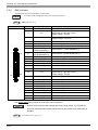
2.3.1
Serial Interfaces (COM1/COM2/COM3/COM4)
This interface is used to connect an RS-232C (serial) cable. A D-sub 9pin plug connector is used.
Pin
Arrangement
5
9
1
6
Pin No.
RS-232C
1
2
3
4
5
6
7
8
Signal Name
CD
RD(RXD)
SD(TXD)
ER(DTR)
SG(GND)
DR(DSR)
RS(RTS)
CS(CTS)
Direction
Input
Input
Output
Output
Input
Output
Input
9
CI(RI)/5V
Input/Output
FG
FG
-
Meaning
Carrier Detect
Receive Data
Send Data
Data Terminal Ready
Signal Ground
Data Set Ready
Request to Send
Send Available
Called status display/+5V Output
(Switching available*1)
Frame Ground
(Common with SG)
*1 Number 9 pin's [RI/+5V]changeover is good only for COM2 and COM3. The factory default setting is
[RI]. For COM1 and COM4, [RI] can be available.
Use #4-40 (UNC) fixing clamps to fix the joint of the interspace.
• The ground (GND) is a signal ground. Make sure to connect it with the other unit’s
SG (Signal Ground) pin.
• The COM4 is not allowed to use when the communication procedure to the Touch
Panel is applied to a COM port connecting.
2-12
Chapter 2 Specifications
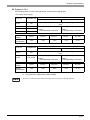
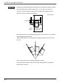
RI/5V Changeover
Switching [RI/5V] for COM2 and COM3 uses the RI/5V changeover switch - it is placed on the board inside
of the rear maintenance cover of the PL. Refer to the following for more details of how to remove the fan
cover or the memory slot cover.
SEE
3.1.1 Uninstalling the Rear Maintenance Cover (page3-2)
• When you switch the RI/5V changeover switch, you must turn off the power supply of the PL. Otherwise, it will cause malfunction.
• Prior to the switching action, confirm the interface specification for the other side
of the connection. Otherwise, it will cause malfunction.
<Magnified image>
+5V
RI
COM2
RI
+5V
COM3
RI/5V Changeover Switch
Main Memory
The factory setting of both ports is [RI].
2-13
PL-6930 / PL-7930 Series User Manual
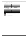
2.3.2
RAS Interface
Specification for D-sub 25pin Male is listed below.
• Correspond with the DipSW setting for using the connector.
DipSW (page1-4)
SEE
Pin Arrangement
Pin No.
1
Signal Name
GND
2
+5V
3
+12V
4
5
6
9
10
11
12
13
14
NC
RST(+)
DIN0(+)
DOUT2 (-)
(UPS Shutdown(-))
DOUT2 (+)
(UPS Shutdown(+))
DOUT0 (-)
DOUT0 (+)
RST (-)
DIN0 (-)
DIN1 (+)
GND
15
+5V
16
17
18
19
20
21
22
23
24
25
DIN2 (+)
DIN2 (-)
DIN3 (+)
DOUT1(-)
DOUT1(+)
DOUT3(-)
DOUT3(+)
DIN3 (-)
DIN1 (-)
NC
7
1
14
8
25
13
Meaning
Ground
Output Current : Lower than or equal to 100mA
(with a total of 2 pin and 15 pin)
Output Voltage : 5V±5%
Output Current : Lower than or equal to 100mA
Output Voltage : 12V±5%
Reset Input (+)
Data Input 0 (+)
Data Output 2 (-) (UPS Shutdown(-))
Data Output 2 (+)(UPS Shutdown(+))
Data Output 0 (-)
Data Output 0 (+)
Reset Input (-)
Data Input 0 (-)
Data Input 1 (+)
Ground
Output Current : Lower than or equal to 100mA
(with a total of 2 pin and 15 pin)
Output Voltage : 5V±5%
Data Input 2 (+)
Data Input 2 (-)
Data Input 3 (+)
Data Output 1(-)
Data Output 1(+)
Data Output 3(-)
Data Output 3(+)
Data Input 3(-)
Data Input 1(-)
-
Use #4-40 (UNC) fixing clamps to fix the joint of the interspace.
• Be sure to use only the rated voltage level when using the No. 2 [+5V] and No.
3[12V] for external power output. Failure to do so can lead to a unit malfunction or
accident.
SEE
2-14
7.1 RAS Features (page7-2)
Chapter 2 Specifications
Input (DIN0, 1, 2, 3 and RST)
INPUT VOLTAGE RANGE
DC12V to 24V
INPUT CURRENT
Lower than or equal to10mA
INNER RESISTOR
3.6k Ω 1/10W
INSULATION
Greater than or equal to 500V
SINK SOURCE INPUT
Correspondence
Output (DOUT0, 1, 2, 3)
OUTPUT VOLTAGE RANGE
DC24V
OUTPUT CURRENT
Lower than or equal to 120mA
INSULATION
Greater than or equal to 500V
PROTECTION DIODE
Equipped
• For further details of the circuit diagram, refer to the following.
SEE
7.1.1 RAS Features (page7-2)
2-15
PL-6930 / PL-7930 Series User Manual
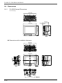
2.4 Dimensions
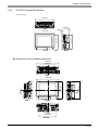
2.4.1
PL-6930 External Dimensions
Unit: mm [in.]
330[12.99]
Top
170[6.69]
287[11.30]
271[10.67]
13[0.51]
346[13.62]
Front
Side
Dimensions with installation fasteners
342[13.46]
236[9.29]
Top
Side
Front
Side
10[0.39]
264[10.39]
2-16
Bottom
283[11.14]
5[0.20]
293[11.54]
8[0.31]
352[13.86]
Chapter 2 Specifications
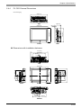
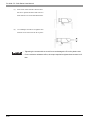
PL-6931 External Dimensions
Unit: mm [in.]
330[12.99]
287[11.30]
346[13.62]
123[4.84]
13[0.51]
271[10.67]
Top
Side
Front
Dimensions with installation fasteners
342[13.46]
236[9.29]
Top
Side
Front
283[11.14]
5[0.20]
293[11.54]
352[13.86]
8[0.31]
2.4.2
Side
10[0.39]
264[10.39]
Bottom
2-17
PL-6930 / PL-7930 Series User Manual
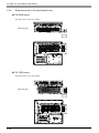
2.4.3
PL-7930 External Dimensions
Unit: mm [in.]
359[14.13]
180[7.09]
Top
325[12.80]
310[12.20]
13[0.51]
374[14.72]
Side
Bottom
Dimensions with installation fasteners
371[14.61]
264[10.39]
11[0.43]
Top
Side
30[1.18]
2-18
Bottom
147[5.79]
322[13.07]
120[4.72]
24[0.94]
Side
Front
142[5.59]
108[4.25]
332[13.07]
26[1.02]
108[4.25]
120[4.72]
381[15.00]
Chapter 2 Specifications
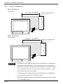
PL-7931 External Dimensions
Unit: mm [in.]
359[14.13]
Top
134[5.28]
325[12.80]
310[12.20]
13[0.51]
374[14.72]
Front
Side
Dimensions with installation fasteners
371[14.61]
264[10.39]
11[0.43]
Top
Side
Front
322[13.07]
24[0.94]
120[4.72]
108[4.25]
332[13.07]
108[4.25]
120[4.72]
381[15.00]
26[1.02]
2.4.4
Side
30[1.18]
142[5.59]
147[5.79]
Bottom
2-19
PL-6930 / PL-7930 Series User Manual
2.4.5
Dimensions attached RS-232C/RS-485 exchangeable unit
PL-6930
Unit: mm [in.]
(Except for
protrudent objects
and cable parts)
Front
60
[2.36]
Bottom
Side
31
[1.22]
55
[2.17]
Top
90
[3.54]
PL-6931
Front
Bottom
2-20
60
[2.36]
Side
90
[3.54]
31
[1.22]
55
[2.17]
Top
Chapter 2 Specifications
PL-7930
Unit: mm [in.]
(Except for
protrudent objects
and cable parts)
Front
60
[2.36]
Bottom
31
[1.22]
55
[2.17]
Top
Side
120
[4.72]
PL-7931
Front
Bottom
60
[2.36]
Side
31
[1.22]
55
[2.17]
Top
120
[4.72]
2-21
PL-6930 / PL-7930 Series User Manual
2.4.6
Dimensions with a full-sized board cover
PL-6930 series
The figure shows a PL-6931 model.
Unit: mm [in.]
54
[2.13]
PL-7930 series
The figure shows a PL-7930 model.
Unit: mm [in.]
55
[2.17]
2-22
Chapter 2 Specifications
• Prior to installing a full-sized board and the PL’s full-sized cover (PL-FC200/PLFC210), be sure that the PL is installed in its attachment panel/cabinet. Due to
dimension differences, a full-sized expansion board and PL’s full-sized cover can
not be attached prior to installing the PL into a panel.
•
When using a full sized expansion board, be sure to check its dimensions and
shape, since they will affect the board’s environment specifications, such as for
vibration, etc.
• There are two types of full-sized covers - one for 4-slot units (PL-6930/7930) and one for
2-slot units (PL-6931/7931). Use an appropriate cover.
SEE
1.3 Accessories (page1-7)
2-23
PL-6930 / PL-7930 Series User Manual
2.4.7
Panel Cut Dimensions
PL-6930 Series
Unit: mm [in.]
+0.5
-0
+0.02
[13.03 -0
]
equal to or less than 4-R3
272.0
+0.5
+0.02
]
-0 [10.71 -0
331.0
PL-7930 Series
+0.5
360.0 -0
+0.02
[14.17-0
]
equal to or less than 4-R3
311.0
+0.5
+0.02
-0 [12.24 -0 ]
Unit: mm [in.]
• The thickness of the installation panel is from 1.6mm[0.06in.] to 10 mm[0.39in.].
• Depending on the shape of the PL’s panel, it may need some reinforcements.
Especially, if high levels of vibration are expected and the PL’s installation surface
(i.e. an operation panel’s door, etc.) can move (i.e.open or close) due consideration should be given to the PL’s weight.
• To insure that the PL’s water resistance is maintained, be sure to install the PL
into a panel that is flat and free of scratches or dents.
• Be sure all installation tolerances are maintained to prevent the unit from falling
out of its installation panel.
2-24
Chapter 2 Specifications
Installation Fasteners
Unit: mm [in.]
11[0.43]
16 [0.63]
16.6 [0.65]
M6
31 [1.22]
∅10[0.39]
2.4.8
2-25
PL-6930 / PL-7930 Series User Manual
Memo
2-26
3
Peripheral Device
Installation
1. Installing optional units / expansion boards
2. Installing / Uninstalling PCMCIA Cards
3. Installing USB Cable Clamp
This chapter shows how to install the unit and expansion board to the PL, and to install peripheral device to
the PL.
3-1
PL-6930 / PL-7930 Series User Manual
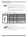
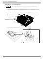
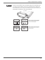
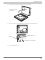
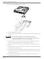
3.1 Installing optional units / expansion boards
A wide variety of optional units, DIM module, CF cards, manufactured by Digital Electronics Corporation
and commercial Expansion boards (PCI/ISA bus compatible board) can be used with the PL. When installing
those optional units, refer to the “Installation Guide” of each unit.
Be sure to confirm that power is not supplied to the PL unit before installing or removing
any optional units, DIM module, CF cards, or Expansion boards (PCI/ISA boards). Failure
to do so can result in an electric shock.
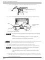
• Use a screwdriver to loosen and tighten the screws. Be sure not to tighten the
screws too much. Excessive force to the unit may cause damage.
• When removing or replacing screws, be careful that they do not fall inside the PL
unit's chassis.
• When the PL is in Soft OFF state, its screen looks “OFF” but some part of the
PL’s circuit still carries electricity. Make sure that no power cable has been
plugged to the PL unit at installation.
3.1.1
Uninstalling the Rear Maintenance Cover
Follow the steps given below when uninstalling the rear maintenance cover.
• The cover is made of aluminum so it is easy to bend or change its shape. Pay
special attention to the uninstalling operation.
PL-6930/PL-7930 (4slot-type unit)
• Make sure to remove the maintenance cover first, and then the half cover.
(1)
Turn off the power and uninstall the power cable. Place the PL unit on a horizontal place as its screen
side could face to the bottom.
3-2
Chapter 3 Peripheral Device Installation
(2)
Unscrew the five(5) attachment screws of the rear maintenance cover in place.
Rear Maintenance Cover
(3)
Remove the rear maintenance cover.
Half Cover
(4)
Lift up slightly the hooks of the half cover and remove it from the unit.
Hooks
Half Cover
3-3
PL-6930 / PL-7930 Series User Manual
PL-6931/PL-7931 (2slot-type unit)
• Make sure to remove the half cover first, and then the maintenance cover.
(1)
Turn off the power and uninstall the power cable. Place the PL unit on a horizontal place as its screen
side could face to the bottom.
(2)
Unscrew the four(4) attachment screws of the rear maintenance cover and the half cover in place.
Half Cover
Rear Maintenance Cover
(3)
Remove the rear maintenance cover.
Hooks
Half Cover
3-4
Chapter 3 Peripheral Device Installation
(4)
3.1.2
Lift up slightly the hooks of the half cover and remove it from the unit.
Installing the Main Memory
• Since DIM module sockets are easy to break, be sure to install the DIM module
• very carefully.
(1)
Uninstall the rear maintenance cover and the half cover.
SEE
(2)
3.1.1 Uninstalling the Rear Maintenance Cover (page3-2)
Install the main memory shown as the following figures. Put the DIM module in the connector at a tilt
then push it all the way. Next, push it down until it can engage tightly with the stopper.
Connector
Main Memory
2
1
DIM module
Stopper
(3)
Return both of the rear maintenance cover and half cover to the unit. Screw the screws to install them on
the unit. The requirement torque force is 0.5N•m to 0.6N•m.
3-5
PL-6930 / PL-7930 Series User Manual
3.1.3
Uninstalling / Installing HDD units / CF card units
• The HDD units and CF card units are precision instruments. Be sure not to jar or
shake them unnecessarily. Read through the Installation Guide for each unit
when using.
• When installing/uninstalling the CF cards, follow the steps as the following procedures
(Procedures of HDD unit).
(1)
Turn off the power switch of the PL. Remove the power cable from the unit.
(2)
Remove the Expansion Slot 0 cover's two (2) attachment screws.
(3)
Grasp the HDD unit's handle and insert it slowly into the PL unit along with the guideways. Be sure you
do not damage the unit.
Expansion Slot1
Expansion Slot0
(4)
Fix the unit in place with its two(2) attachment screws.
• Do as same as above when installing/uninstalling to the Expansion Slot1 card units.
3-6
Chapter 3 Peripheral Device Installation
• Be sure to use the HDD/CF card unit as Master setting for PL-X930 Series units.
• If you want to use the HDD/CF card unit in the “Expansion Slot1” together with
the CD-ROM drive unit, the setting of the HDD/CF card unit must be “Master” (as
the first disk). To do failure so, it may cause malfunction.
<PL-HD240>
Slave Setting
Master Setting
for use as slave
for use as Master
When using the PL-HD240 as a Master,
be sure to remove the jumper plug, as
shown in the left side figure.
Jumper Plug
Slave Setting
Master Setting
for use as slave
for use as Master
When using the PL-CF200 as a Master,
be sure to shift the switch, as shown in
the left side figure.
3-7
PL-6930 / PL-7930 Series User Manual
3.1.4
Installing the Expansion board (PCI/ISA)
(1)
Uninstall the rear maintenance cover of the PL unit.
SEE
3-8
3.1.1 Uninstalling the Rear Maintenance Cover (page3-2)
(2)
Unscrew the one screw of the blank panel then uninstall the panel.
(3)
Remove the dust cover from the expansion slot, and insert the expansion board there.
(4)
Fix the steel plate by the attachment of the expansion board.
(5)
Return the rear maintenance cover and the half cover to the unit then screw the screw to fix.
Chapter 3 Peripheral Device Installation
3.1.5
Connecting a CD-ROM drive unit
• If you want to use the HDD/CF card unit in the “Expansion Slot1” together with
the CD-ROM drive unit, the setting of the HDD/CF card unit must be “Master” (as
the first disk). To do failure so, it may cause malfunction. Please refer to the
Chapter 3 Uninstalling / Installing HDD units / CF card units (page3-6)
PL-6930 / PL-7930(4-Slot Type)
(1)
Unscrew the two(2) attachment screws on the IDE cover, and then remove the cover.
(2)
Unscrew two (2) attachment screws of the Expansion Slot1 and then remove the cover.
IDE cover
Expansion Slot1 cover
(3)
Secure the attachment bracket for the rear face to the PL unit using the two (2) attachment screws.
The torque should be 0.5 to 0.6N•m.
Attachment Bracket for the Rear Face
3-9
PL-6930 / PL-7930 Series User Manual
(4)
Secure the front face fastener to the bottom of the CD-ROM unit using the two (2) attachment screws.
The torque should be 0.5 to 0.6N•m.
• Insert firmly both sides of parts, which are marked with thick circles (salients and holes) on the
above.
(5)
Connect the CD unit to the PL unit via the connection cable, folded the cable over, along the diagonal
line. Be sure to confirm that the Cable's #1 pin mark and the connector are correctly aligned. Do not connect anything to the DC INPUT Connector.
1 Pin Mark
DC Input Connector
• Make sure that the cable is securely plugged into the connector before you turn
on the power switch.
• Refer to the following drawings to confirm that the connection cable is securely
attached to both connectors. Be sure to check both connectors before turning the
PL ON, since incorrect attachment of the connectors can cause equipment
damage.
×
3-10
×
Chapter 3 Peripheral Device Installation
(6)
Secure the CD-ROM unit to the PL unit using the four (4) attachment screws. The torque should be 0.5
to 0.6N•m. Place the cable in the space between the PSS-CD01 and the PL unit.
• When using the HDD/CF Card unit within the Expansion Slot 1 for PL-X930
Series, Step (6) is not required. PSS-CD01 should be used, unattached on the
rear of PL unit.
3-11
PL-6930 / PL-7930 Series User Manual
PL-6931 / PL-7931(2-Slot Type)
(1)
Unscrew the two(2) attachment screws on the IDE cover, and then remove the cover.
(2)
Unscrew two (2) attachment screws of the Expansion Slot1 cover and then remove the cover
IDE cover
Expansion Slot1 cover
(3)
Secure the attachment bracket for the rear face to the PL unit using the two (2) attachment screws. The
torque should be 0.5 to 0.6N•m.
Attachment Bracket for the Rear Face
3-12
Chapter 3 Peripheral Device Installation
(4)
Secure the front face fastener to the bottom of the CD-ROM unit using the two (2) attachment screws.
The torque should be 0.5 to 0.6N•m.
(5)
Connect the CD unit to the PL unit via the connection cable, folded the cable over, along the diagonal
line. Be sure to confirm that the Cable's #1 pin mark and the connector are correctly aligned. Do not anything connect to the DC INPUT Connector.
1 Pin Mark
DC Input Connector
• Make sure that the cable is securely plugged into the connector before you turn
on the power switch.
• Refer to the following drawings to confirm that the connection cable is securely
attached to both connectors. Be sure to check both connectors before turning the
PL ON, since incorrect attachment of the connectors can cause equipment
damage.
×
×
3-13
PL-6930 / PL-7930 Series User Manual
(6)
Secure the CD-ROM to the PL unit using the four (4) attachment screws. The torque should be 0.5 to
0.6N•m. Place the cable in the space between the PSS-CD01 and the PL unit.
• When using the HDD/CF Card unit within the Expansion Slot 1 for PL-X931
Series, Step (6) is not required. PSS-CD01 should be used, unattached on the
rear of PL unit.
3-14
Chapter 3 Peripheral Device Installation
3.2 Installing / Uninstalling PCMCIA Cards
PL series accept commercial PC cards on the market.
(1)
Unscrew the two(2) screws on the cover of the side of the PCMCIA, and then remove the cover.
Eject Button
(2)
To remove the PC card, press the eject button twice. (When you press the button for the first time, the tip
of the eject button pokes out. The PC card is pushed out at the second time.)
(3)
Return the PCMCIA cover to the unit, and then drive the screws to fix the cover.
• If your PC card is a cable attachment type, you should consider an effective
prevention measure that the installing of the cable does not drop out of the clamp.
The cable fixation may not be stable if there is vibration.
• When energizing to the PL, be sure to stop the PL unit PC Card’s driver prior to
removing the PC Card. A failure to stop this driver may result in damage to either
the PC Card, the PC Card's data, or may cause the Windows program to hang
up. For information on the procedure for stopping the PC Card’s driver, refer to
your OS' User Manual.
3-15
PL-6930 / PL-7930 Series User Manual
3.3 Installing USB Cable Clamp
In the use of USB connection devices, installing a gasket and clamp makes the USB cable firmly fasten. This
installation prevents the USB plug from falling out of the unit.
(1)
Install the bracket in the USB interface side of the unit.
(2)
Plug the USB cable into the unit. Tie up the cable and clamp to fix firmly.
Bracket
Clamp
• If you fix two USB cables together, tie them up with one USB clamp.
3-16
4
Installation and
Wiring
1. Installing the PL unit
2. Wiring
This chapter shows how to install the PL unit and to care the wiring method.
4-1
PL-6930 / PL-7930 Series User Manual
4.1 Installing the PL unit
This section describes the procedures and precautions for installing the PL unit.
4.1.1
Installation Procedures
Follow the steps given below when installing the PL.
Check the Installation Gasket’s Seating
It is strongly recommended that you use the installation gasket, since it absorbs vibration in addition to
repelling water.
For the procedure for attaching the installation gasket, refer to the following.
SEE
8.4 Replacing the Installation Gasket (page8-5)
• Before installing the PL into a cabinet or panel, check that the installation gasket is
securely attached to the unit.
• A gasket which has been used for a long period of time may have scratches or dirt
on it, and could have lost much of its dust and drip resistance. Be sure to change
the gasket periodically as the scratches or dirt on the gasket becomes visible.
Creating a Panel Cut
Create the correct sized opening required to install the PL, using the installation dimensions given.
The installation gasket and the installation fasteners are required when installing the PL.
SEE
2.4.7 Panel Cut Dimensions (page2-24)
Panel
Panel Cut
Area
• Check that the installation panel or cabinet’s surface is flat, in good condition and has no
jagged edges. Also, if desired, metal reinforcing strips can be attached to the inside of the
panel, near the Panel Cut, to increase the panel’s strength.
4-2
Chapter 4 Installation and Wiring
• Panel thickness should be from 1.6mm [0.06 in.] to 10.0mm [0.29 in.]. Decide the
panel’s thickness based on the level of panel strength required.
1.6mm [0.06 in.] to 10.0mm [0.39 in.]
• For easier maintenance, operation, and improved ventilation, be sure to install
the PL at least 50 mm [1.97 in.] away from adjacent structures and other equipment.
Unit: mm [in.]
50
[1.97]
50
[1.97]
50
[1.97]
50
[1.97]
50
[1.97]
50
[1.97]
50
[1.97]
4-3
PL-6930 / PL-7930 Series User Manual
• Be sure that the ambient operation temperature and the ambient humidity are within
their designated ranges. When installing the PL on the panel of a cabinet or
enclosure, “Ambient operation temperature” indicates both the panel face and
cabinet or enclosure’s internal temperature.
Unit: mm [in.]
100 [3.94]
30 [1.18]
Panel
face
30 [1.18]
Inside of the
enclosure
• Be sure that heat from surrounding equipment does not cause the PL to exceed its
standard operating temperature.
• When installing the PL in a slanted panel, the panel face should not incline more
than 30°.
30° or less
• The PL Series unit does not support longitudinal mounting.
• Any electromagnetic switch or Non Fuse breaker that generates arc should be
placed away from the PL.
4-4
Chapter 4 Installation and Wiring
Installing the PL
(1)
Insert the PL into the panel cut, as shown.
(2)
Insert the installation fasteners into the PL
insertion slots on the left, right, top, and
Installation Panel
bottom of the unit. (8 slots for PL-6930
Series and 12 slots for PL-7930 Series)
Hook
PL-6930 Series
Slots
Slots
PL-7930 Series
Slots
Slots
4-5
PL-6930 / PL-7930 Series User Manual
(3)
Insert each of the fasteners shown below.
Be sure to pull the fastener back until it is
flush with the rear of the attachment hole.
(4)
Use a Phillips screwdriver to tighten each
fastener screw and secure the PL in place.
• Tightening the screws with too much force can damage the PL unit’s plastic case.
• For the moisture resistance effect, the torque required to tighten these screws is 0.5
N•m.
4-6
Chapter 4 Installation and Wiring
4.2 Wiring
This section describes the procedures and precautions to install the PL unit.
4.2.1
Connecting the Power cord
To avoid an electric shock, prior to connecting the PL unit’s power cord terminals to the
power terminal block, confirm that the PL unit’s power supply is completely turned OFF, via
a breaker, or similar unit.
The PL is designed to use AC100V/240V input. Supplying a power voltage other than that
specified will damage the power source and the PL unit.
When the FG terminal is connected, be sure the wire is grounded to avoid an electric shock
at breakdown.
• When the FG terminal is connected, be sure the wire is grounded. Not grounding
the PL unit will result in excess noise and vibration.
• The SG and FG terminals are connected internally in the PL unit.
• When connecting the SG wire to another device, be sure that the design of the
system/connection does not produce a shorting loop.
Connect the power cord to the power plug on the rear of the PL unit. The power plug can be removed from
Socket part of the PL unit.
Rear Side
N
L FG
Power Plug
Power Connector
4-7
PL-6930 / PL-7930 Series User Manual
Power cord specifications
Power Cable Size
0.75mm² to 2.5mm² (18AWG to12AWG)
Type of Cable Core
Single or Strand Wire
10mm [0.39in.]
Cable Core Length
• Use copper conductors only.
• When using the Strand Wire, if the Conductor's end (individual) wires are not twisted
correctly, the end wires may either short against each other, or against an electrode.
Wiring
When connecting the Power Cord, use the following items when performing wiring. (The items are
manufactured by Phoenix Contact.) *1
Recommended Tool
SZS 0.6X3.5 (1205053)
Recommended Pin
Terminals
AI 0.75-10GY
AI 1-10RD
AI 1.5-10BK
AI 2.5-12BUK
Recommended Pin
Terminal Crimp Tool
CRIMPFOX ZA3 (1201882)
(3201288)
(3200182)
(3200195)
(3200962)
• The power supply plug FKC-2.5/3-STF-5.08 is manufactured by Phoenix Contact.
*1
4-8
For further details, please contact your local Phoenix Contact distributor.
Chapter 4 Installation and Wiring
Connecting the Power Cord
• To prevent the possibility of a terminal short, use a pin terminal that has an
insulating sleeve.
• The temperature rating of field installed conductors: 75°C only.
(1)
Confirm that the power cord is unplugged from the power supply.
(2)
Open the cable attachment holes of the Power Plug. There are Open Buttons next to the holes corresponding to each of cable cores. Push that button with a straight slot screwdriver etc., and the button
opens.
(3)
Insert the crimp-type pin terminal of the cable core completely into the hole with the Open Button
pushed. When stopping pushing the button, the hole shuts and the cable is fixed.
Black
White
(AC Power Cord included in the package)
Open Button
L
N
FG
Green/Yellow
• Confirm that all wires are connected correctly.
• The torque required to tighten these screws is 0.5N•m to 0.6N•m.
• To prevent the possibility of a terminal short, use a pin terminal that has an
insulating sleeve.
• The temperature rating of field installed conductors: 75oC or less.
(4)
Insert the power plug into the socket of the PL, then screw both of the minus (-) screws to fix. The torque
required to tighten these screws is 0.5N•m to 0.6N•m.
4-9
PL-6930 / PL-7930 Series User Manual
4.2.2
Connecting the Power Supply
This section describes the precautions for supplying a power voltage.
• If the supplied voltage exceeds the PL unit's range,
Twisted-pair cord
connect a constant voltage transformer.
Constant
Voltage
Transformer
PL Unit
FG
SEE
Electrical (page2-2)/ Electrical
(page2-4)/
• For between the line and ground or between the lines,
Twisted-pair cord
select a power supply that is low in noise. If there is an
Insulating
Transformer
PL Unit
FG
excess amount of noise, connect an insulating transformer.
• Use constant voltage and
insulating transformers with
PL Unit
Main Power
capacities of 200VA or more.
PL Power
• When supplying power to the PL unit, please separate
Power
Input/Output
Input/Output
Unit
the input/output and operation unit lines, as shown.
• To increase the noise resistance quality of the power
cord, it is recommended to attach a ferrite core to the
power cord.
Main
Power
PL
Power
• The power supply cord must not be bundled or
PL Unit
T1
T2
Power
Input/
Output
Main
Circuit
positioned close to main circuit lines (high voltage,
high current), or input/output signal lines.
Input/Output
Unit
Input/Output
Unit
• Connect a lightening surge absorber, as shown in the
diagram, to deal with power surges.
• To avoid excess noise, make the power cord short
enough as it can be.
Operation
Unit
• Be sure to ground the surge
absorber (E1) separately from
the PL unit (E2).
PL Unit
FG
E1
E2
• Select a surge absorber that has
a maximum circuit voltage
greater than that of the peak
voltage of the power supply.
Lightening Surge
Absorber
4-10
Chapter 4 Installation and Wiring
4.2.3
Grounding Precaution
This section describes the precautions for grounding the PL unit.
Do not use common grounding. It can lead to an accident or machine breakdown.
(a)Exclusive Grounding (BEST)
• When supplying power to the PL unit, be sure to
separate the input/output and power lines, as shown.
PL Unit
Other
Equipment
[diagram (a)]
• Check that the grounding
resistance is 100Ω or less.
• FG and SG terminals are
internally connected in the PL.
When connecting an external
device to the PL using the SG
(b) Common Grounding (OK)
terminal, be sure to check that
PL Unit
Other
Equipment
no short-circuit loop is created
when you setup the system.
• The grounding wire should have
a cross sectional area of 2mm2
or greater. Create the
connection point as close to the
(c)Common Grounding (Not OK)
PL unit as possible, and make
the wire as short, as possible.
When using a long grounding
PL Unit
Other
Equipment
wire, replace the thin wire with a
thicker wire, and place it in a
duct.
• If exclusive grounding is not possible, use a common
connection point. [diagram (b)]
• If the equipment does not function
properly when grounded, disconnect
the ground wire from the FG terminal.
4.2.4
I/O Signal Line Placement Precaution
•
Input and output signal lines must be separated from the power control cables for operating circuits.
•
If this is not possible, use a shielded cable and ground the edge of the shield.
4-11
PL-6930 / PL-7930 Series User Manual
Memo
4-12
5
System Setup
1. Setup Procedures
2. System Parameters
This chapter explains how to enter the PL system settings, as well as the cautions required both before and
during set up.
5-1
PL-6930 / PL-7930 Series User Manual
5.1 Setup Procedures
The BIOS setting up procedures are the following.
• Normally, use only the factory (default) settings.
(1)
Connect a USB keyboard to the PL.
(2)
Turn the PL’s power ON.
(3)
After the boot-up screen comes up, press the [F2] key until the following screen appears.
Menu
KEYBOARD ACTION KEYS
Provides a summary of the keyboard keys used to carry out the set-up.
Help area
Shows the information of
the items you selected.
SYSTEM SETTING SELECTION AREA
Each of the titles (areas) listed here contains system setting items.
(4)
To use the [
][
] arrow keys, change the menu contents. A setting screen of each system will be
][
] arrow keys, move up and down the cursor to select an item of the system, then
displayed.
(5)
To use the [
confirm it by the [Enter] key. Now you can set up the item you selected.
5-2
Chapter 5 System Setup
5.2 System Parameters
Select the items to set up the system information. Here, we introduce the system parameters of each item.
• Normally, use only the factory (default) settings.
5.2.1
Main
System Time
Shows the time which the PL currently recognizes. Set a proper time for the PL by moving the cursor with the
[Tab] key or using the [+] and [-] keys because the factory default setting is the Japan’s Standard Time
(GMT+09:00).
System Date
Shows the date which the PL currently recognizes. Set a proper date for the PL by the [+] and [-] keys.
Primary Master / Primary Slave / Secondary Master / Secondary Slave
Displays the name of devices connected to the PL. Pressing the [Enter] key will call up the Parameter settings
menu.
SEE
Primary Master / Primary Slave / Secondary Master / Secondary Slave (page5-4)
System Memory
Shows the capacity of the “System Memory”.
Extended Memory
Shows the capacity of the “Extended Memory”. It is the loaded memory - the size of the Video Memory 2048K bytes.
5-3
PL-6930 / PL-7930 Series User Manual
Primary Master / Primary Slave / Secondary Master / Secondary Slave
Point out the cursor at the [Primary Master], [Primary Slave], [Secondary Master], or [Secondary Slave] on
the “Main screen”, and then press the [Enter] key, so that the following screen is shown.
Type
Specifies a type of drive which you use. Select from [Auto], [None], [ATAPI Removable], [CD-ROM], [IDERemovable], [Other ATAPI], or [User]. The factory default type is [Auto].
Total Sectors
Shows the number of disk sectors connected to the unit.
Maximum Capacity
Shows the maximum capacity of the disk connected to the unit.
Multi Sector Transfers
Specifies the number of sectors per block, which are transferred to the memory.When the [Type] is [None],
nothing is displayed. In other cases, select from [Disabled], [2 Sectors], [4 Sectors], [8 Sectors], or [16
Sectors].
LBA Mode Control
Enables or disables the Logical Block Addressing (LBA) instead of the Cylinders, Headers, and Sectors.
When the [Type] is [None], nothing is displayed. In other cases, select from [Disabled] or [Enabled].
32 Bit I/O
Enables or disables the 32 bit transferring between CPU and IDE controller. The choice is [Enabled] or
[Disabled]. When the [Type] is [None], nothing is displayed.
5-4
Chapter 5 System Setup
Transfer Mode
Specifies a method of transferring data. When the [type] is [None], nothing is displayed. In other cases, select
from [Standard], [Fast PIO 1], [Fast PIO 2], [Fast PIO 3], [Fast PIO 4], [FPIO 3/DMA 1], or [FPIO 4/DMA 2]
Ultra DMA Mode
Specifies a Ultra DMA mode for the Hard drive. When the [type] is [None], nothing is displayed. In other
cases, select from [Disabled], [Mode 0], [Mode 1], [Mode 2], [Mode 3], [Mode 4], or [Mode 5].
5-5
PL-6930 / PL-7930 Series User Manual
5.2.2
Advanced
Installed O/S
Specifies a type of OS of the unit. Select from [Other], [Win95], [Win98], [WinMe], or [Win2K/XP]. The
factory default setting is [Win2K/XP].
Reset Configuration Data
Specifies whether you want to reset the Plug & Play information which is recorded in the Extended System
Configuration Data (ESCD) Block of the CMOS RAM, when the system boots up next time. The choice is
[Yes] or [No] and the factory default setting is [No].
Large Disk Access Mode
When you use UNIX or NetWare for OS, the setting should be [Other]. The choice is [DOS] or [Other] and
the factory default setting is [DOS].
Local Bus IDE adapter
Specifies an enabled/disabled state for the IDE controller. Select from [Both], [Primary], [Secondary], or
[Disabled]. The the factory default setting is [Both].
Advanced Chipset Control
Point the cursor to the [Advanced Chipset Control] and press the [Enter] Key, so that you can set up details.
SEE
5-6
Advanced Chipset Control (page5-9)
Chapter 5 System Setup
I/O Device Configuration
Point the cursor to the [I/O Device Configuration] and press the [Enter] Key, so that you can go to the Serial
Port Setting screen
SEE
I/O Device Configuration (page5-11)
Keyboard Features
Point the cursor to the [Keyboard Features] and press the [Enter] Key, so that you can go to the keyboard setup screen.
SEE
Keyboard Features (page5-12)
Cache Memory
Point the cursor to the [Cache Memory] and press the [Enter] Key, so that you can go to the set-up screen for
Cache Memory.
SEE
Cache Memory (page5-13)
PCI Configuration
Point the cursor to the [PCI Configuration] and press the [Enter] Key, so that you can go to the set-up screen
for PCI IRQ.
SEE
PCI Configuration (page5-15)
DMI Event Logging
Point the cursor to [DMI Event Logging] and press the [Enter] Key to go to the set-up screen for DMI event
logging.
SEE
DMI Event Logging (page5-17)
Disable ACPI_Sx
Specifies the API’s state. Select from [None], [S1]. With this action, the selecting state will be enabled. The
factory default setting is [None].
Legacy USB Support
Specifies an enabled/disabled state for the USB when the USB keyboard etc. is used under DOS. The choice
is [Enabled] or [Disabled]. The factory default setting is [Enabled].
Enable Memory gap
Specifies an enabled/disabled state for the Memory gap. The choice is [Enabled] or [Disabled]. The factory
default setting is [Disabled].
Summary screen
Specifies whether you need to display the Summary screen in running the daisy-chained devices. The choice
is [Enabled] or [Disabled]. The factory default setting is [Disable].
QuickBoot Mode
Specifies whether the system boot-up should be “QuickBoot mode”. When the choice is [Disabled], it will
execute a system test at the system starting-up. The factory default setting is [Enabled].
5-7
PL-6930 / PL-7930 Series User Manual
Extended Memory Testing
Specifies whether a test for the Extended Memory needs to be executed at the system starting-up. The test
types are listed below. The factory default setting is [Just Zero it].
[Normal]
Normal test
[Just Zero it] Simple test
[None]
No test
Show CMOS Checksum Error
Specifies whether you need to display the errors in case CMOS Checksum Error occurs. The choice
is [Enabled] or [Disabled]. The factory default setting is [Disabled].
Clear CMOS Data Area
Specifies whether you need to Clear CMOS Data Area. The choice is [Enabled] or [Disabled]. The factory
default setting is [Disabled].
Power On Delay
Specifies whether the system waits during boot-up. Select from [Enabled] or [Disabled]. When [Enabled] is
selected, the system waits about 4 seconds during boot-up. The factory default setting is [Disabled].
• If a USB device such as USB memory is connected to the PL when the PL is started, the following phenomenon may occur, depending on the device:
• It takes about 1 minute before the OS starts up.
• The PL does not recognize the USB device.
These problems may be solved by setting [Power On Delay] to [Enable].
5-8
Chapter 5 System Setup
Advanced Chipset Control
Point the cursor to the [Advanced Chipset Control] on the [Advanced] screen and press the [Enter] Key, so
that the next screen will be displayed.
DDR SDRAM Configuration
Point the cursor to the [DDR SDRAM Configuration] and press the [Enter] Key, so that you can go to the
Memory Setting screen.
SEE
DDR SDRAM Configuration (page5-10)
ECC Config
Specifies whether the ECC function for memory, which is a function of recovering errors, needs to be used.
This parameter is displayed only when memory with the ECC function is used. Select from [ECC] or [Disabled]. The factory default setting is [Disabled].
ECC Error Type
Specifies the interruption setting when an ECC error occurs. This parameter is displayed only when memory
with the ECC function is used. Select from [None], [NMI], [SMI], or [SCI]. The factory default setting is
[SMI].
SERR signal condition
Specifies error bit(s) for ECC. This parameter is displayed only when memory with the ECC function is used.
Select from [None], [Single bit], [Multiple bit], or [Both]. The factory default setting is [Multiple bit].
5-9
PL-6930 / PL-7930 Series User Manual
DDR SDRAM Configuration
Point the cursor to the [DDR SDRAM Configuration] on the [Advanced Chipset Control] and press the
[Enter] Key, so that the next screen will be displayed.
DDR Speed
Specifies the clock frequency for the memory.
Active to Precharge delay
Specifies the timing of DRAM Precharge processing.
SDRAM RAS# to CAS# Latency
Specifies the latency time for CAS.
RAS# to CAS# Delay
Specifies a transfer timing from RAS to CAS.
RAS# Precharge
Specifies the number of cycles of RAS precharge.
5-10
Chapter 5 System Setup
I/O Device Configuration
Point the cursor to the [I/O Device Configuration] on the [Advanced] screen and press the [Enter] Key, so that
the next screen will be displayed.
On board Serial Port 1
Specifies an enabled/disabled state for the COM1. Select from [Disabled] or [Enabled]. The factory default
setting is [Enabled]. In addition, the factory default setting for Base I/O Address is [3F8], and for Interrupt is
[IRQ 4].
On board Serial Port 2
Specifies an enabled/disabled state for the COM2. Select from [Disabled] or [Enabled]. The factory default
setting is [Enabled]. In addition, the factory default setting for Base I/O Address is [2F8], and for Interrupt is
[IRQ 3].
On board Serial Port 3
Specifies an enabled/disabled state for the COM3. Select from [Disabled] or [Enabled]. The factory default
setting is [Enabled]. In addition, the factory default setting for Base I/O Address is [3E8], and for Interrupt is
[IRQ 11].
On board Serial Port 4
Specifies an enabled/disabled state for the COM4. Select from [Disabled] or [Enabled]. The factory default
setting is [Enabled]. In addition, the factory default setting for Base I/O Address is [2E8], and for Interrupt is
[IRQ 10].
5-11
PL-6930 / PL-7930 Series User Manual
Keyboard Features
Point the cursor to the [Keyboard Features] on the [Advanced Chipset Control] and press the [Enter] Key, so
that the next screen will be displayed.
NumLock
Specifies the NumLock status. Select from [Auto], [On], or [Off]. The factory default setting is [On].
KeyClick
Specifies an enabled/disabled state for the keyboard’s click sound. Select [Enabled] or [Disabled]. The factory
default setting is [Disabled].
Keyboard auto-repeat rate
Specifies the figures of how many times a key can input letters while being pressed for a second. Select from
[30/sec.], [26.7/sec.], [21.8/sec.], [18.5/sec.], [13.3/sec.], [10/sec.], [6/sec.], or [2/sec.]. The factory default
setting is [30/sec.].
Keyboard auto-repeat delay
Specifies a time duration until the auto-repeat function becomes enabled from a key is pressed. Select from [1/
4 sec.], [1/2 sec.], [3/4 sec.], or [1 sec.]. The factory default setting is [1/2 sec.].
5-12
Chapter 5 System Setup
Cache Memory
Point the cursor to the [Cache Memory] on the [Advanced] screen and press the [Enter] Key, so that the next
screen will be displayed.
Memory Cache
Specifies an enabled/disabled state for the Memory Cache. The choice is [Enabled] or [Disabled]. The factory
default setting is [Enabled].
Cache System Bios area
Specifies the cache set-up for the System BIOS area. The choice is [uncached] or [Write Protect]. The factory
default setting is [Write Protect].
Cache Video BIOS area
Specifies the cache set-up for the VIDEO BIOS area. The choice is [uncached] or [Write Protect]. The factory
default setting is [Write Protect].
Cache Base 0-512k
Specifies the cache set-up for the Base Memory, 0k to 512k. Select from [uncached], [Write Through], [Write
Protect], or [Write Back]. The factory default setting is [Write Back].
Cache Base 512-640k
Specifies the cache set-up for the Base Memory, 512k to 620k. Select from [uncached], [Write Through],
[Write Protect], or [Write Back]. The factory default setting is [Write Back].
Cache Extended Memory Area
Specifies the cache set-up for the Extended Memory area. Select from [uncached], [Write Through], [Write
Protect], or [Write Back]. The factory default setting is [Write Back].
5-13
PL-6930 / PL-7930 Series User Manual
Cache xxxx-xxxx
Specifies the cache setting for each address. Select from [Disabled], [USWC Caching] (The address A000 AFFF and B000 - BFFF are only available.), [Write Through], [Write Protect], or [Write Back]. The factory
default setting is as follows.
5-14
A000 - AFFF
Disabled
B000 - BFFF
Disabled
C800 - CBFF
Write Protect (VIDEO Memory)
CC00 - CFFF
Write Protect
D000 - D3FF
Disabled
D400 - D7FF
Disabled
D800 - DBFF
Disabled
DC00 - DFFF
Disabled
E000 - E3FF
Disabled
E400 - E7FF
Write Protect (PXE)
E800 - EBFF
Write Protect
EC00 - EFFF
Write Protect
Chapter 5 System Setup
PCI Configuration
Point the cursor to the [PCI Configuration] on the [Advanced] screen and press the [Enter] Key, so that the
next screen will be displayed.
PCI/PNP ISA IRQ Resource Exclusion
Point the cursor to the [PCI/PNP ISA IRQ Resource Exclusion] and press the [Enter] Key, so that you can go
to the [ISA IRQ] set-up screen.
SEE
PCI/PNP ISA IRQ Resource Exclusion (page5-16)
PCI IRQ line 1 to 8
Specifies the Interrupt Request Lines (IRQ) for PCI. Select from [Disabled], [Auto Select], [3], [4], [5], [7],
[9], [10], [11], [12], [14], or [15]. The factory default setting is [Auto Select].
5-15
PL-6930 / PL-7930 Series User Manual
PCI/PNP ISA IRQ Resource Exclusion
Point the cursor to the [PCI/PNP ISA IRQ Resource Exclusion] on the [PCI Configuration] screen and press
the [Enter] Key, so that the next screen will be displayed.
IRQ3,4,5,7,10,11
Specifies the IRQ which is allocated to the legacy device. Select from [Available] or [Reserved]. The factory
default setting is [Available].
5-16
Chapter 5 System Setup
DMI Event Logging
Specifies the parameters related to DMI event logging. Point the cursor to the [DMI Event Logging] on the
[Advanced] screen and press the [Enter] Key, so that the following screen will be displayed.
Event log validity
Shows the status of the event log storage area. [Valid] is shown when the status is normal, and [Not valid] is
shown when the status is abnormal.
Event log capacity
Shows the status of the area to which event logs are written. [Full] is shown when the area is full, and [Space
Available] is shown when the area is not full.
View DMI event log
Point the cursor to [View DMI event log] and press the [Enter] Key to view the DMI event logs.
Event Logging
Specifies whether event logs need to be recorded. Select from [Enabled] or [Disabled]. The factory default
setting is [Enabled].
ECC Event Logging
Specifies whether the event logs related to memory ECC need to be recorded. Select from [Enabled] or
[Disabled]. The factory default setting is [Enabled].
Mark DMI events as read
Point the cursor to [Mark DMI events as read] and press the [Enter] Key to mark unread event logs as read.
5-17
PL-6930 / PL-7930 Series User Manual
Clear all DMI event logs
Specifies whether all the recorded DMI event logs need to be deleted. Select from [Yes] or [No]. The factory
default setting is [No].
5-18
Chapter 5 System Setup
5.2.3
Intel
CPU Control Sub-Menu
Point the cursor to the [CPU Control Sub-Menu] on the [Intel] screen and press the [Enter] Key, so that you
can go to the [CPU] set-up screen.
SEE
CPU Control Sub-Menu (page5-21)
MCH Control Sub-Menu
Point the cursor to the [MCH Control Sub-Menu] on the [Intel] screen and press the [Enter] Key, so that you
can go to the [MCH] set-up screen.
SEE
MCH Control Sub-Menu (page5-22)
Video (Intel IGD) Control Sub-Menu
Point the cursor to the [Video (Intel IGD) Control Sub-Menu] on the [Intel] screen and press the [Enter] Key,
so that you can go to the set-up screen for display.
SEE
Video (Intel IGD) Control Sub-Menu (page5-24)
ICH Sub-Menu
Point the cursor to the [ICH Control Sub-Menu] on the [Intel] screen and press the [Enter] Key, so that you
can go to the [ICH] set-up screen.
SEE
ICH Control Sub-Menu (page5-25)
5-19
PL-6930 / PL-7930 Series User Manual
ACPI Control Sub-Menu
Point the cursor to the [ACPI Control Sub-Menu] on the [Intel] screen and press the [Enter] Key, so that you
can go to the [ACPI] set-up screen.
SEE
ACPI Control Sub-Menu (page5-27)
APM Control Sub-Menu
Point the cursor to the [APM Control Sub-Menu] on the [Intel] screen and press the [Enter] Key, so that you
can go to the [APM] set-up screen. If you use APM OS, you are requested to set up this configuration.
SEE
APM Control Sub-Menu (page5-28)
Workaround Control Sub-Menu
Point the cursor to the [Workaround Control Sub-Menu] on the [Intel] screen and press the [Enter] Key, so
that you can go to the set-up screen of the whole platform.
SEE
5-20
Workaround Control Sub-Menu (page5-29)
Chapter 5 System Setup
CPU Control Sub-Menu
Point the cursor to the [CPU Control Sub-Menu] on the [Intel] screen and press the [Enter] Key, so that this
screen will be displayed.
Processor Power Management
This is a function that controls the processor’s power state. Select from [Disabled], or [C States Only]. The
factory default setting is [C States Only] and the default should be applied when using.
Thermal Control Circuit
This is a function that protects the CPU’s temperature, and its setting is a situation that if it exceeds the limit
that CPU is able to work properly. Select from [Disabled], [TM1], or [TM2]. The factory default setting is
[TM1] and the default should be applied for use.
5-21
PL-6930 / PL-7930 Series User Manual
MCH Control Sub-Menu
Point the cursor to the [MCH Control Sub-Menu] on the [Intel] screen and press the [Enter] Key, so that this
screen will be displayed.
MCH Power Management Sub-Menu
Goes to the Chipset set-up screen.
SEE
MCH Power Management Sub-Menu (page5-23)
DDR ECC Operation
Specifies whether you use ECC memory or not. The choice is [Enabled] or [Disabled] and the default factory
setting is [Enabled].
5-22
Chapter 5 System Setup
MCH Power Management Sub-Menu
Point the cursor to the [MCH Power Management Sub-Menu] on the [Intel] screen and press the [Enter] Key,
so that this screen will be displayed.
Chipset Thermal Throttling
Specifies a thermal throttle, a system to prevent a themorunway, for chipset. The choice is [Enabled] or
[Disabled]. The factory default setting is [Enabled].
DRPM Support
Specifies an enabled/disabled state for the setting of Dynamic Row Power Management. The choice is
[Enabled] or [Disabled]. The factory default setting is [Enabled].
5-23
PL-6930 / PL-7930 Series User Manual
Video (Intel IGD) Control Sub-Menu
Point the cursor to the [Video (Intel IGD) Control Sub-Menu] on the [Intel] screen and press the [Enter] Key,
so that this screen will be displayed.
IGD-Memory Size
Specifies an allocation capacity for the Video Memory. Select from [UMA=1MB], [UMA=8MB],
[UMA=16MB], or [UMA=32MB]. the factory default setting is [UMA=8MB].
5-24
Chapter 5 System Setup
ICH Control Sub-Menu
Point the cursor to the [ICH Control Sub-Menu] on the [Intel] screen and press the [Enter] Key, so that this
screen will be displayed.
Integrated Device Control Sub-Menu
Goes to the setting screen where an enabled/disabled state for the USB and the LAN and the PCMCIA is
specified.
SEE
Integrated Device Control Sub-Menu (page5-26)
CPU Sleep
Specifies whether the CPU needs power saving. The choice is [Enabled] or [Disabled]. The factory default
setting is [Enabled].
Deeper Sleep in S1M
Specifies whether the CPU needs power saving in the Standby mode for Windows®. The choice is [Enabled]
or [Disabled]. The factory default setting is [Disabled].
PCI Clock Run
Specifies an enabled/disabled state for the usage of PCI Clock Run Protocol for the Card Bus Controller. The
choice is [Enabled] or [Disabled]. The factory default setting is [Disabled].
5-25
PL-6930 / PL-7930 Series User Manual
Integrated Device Control Sub-Menu
Point the cursor to the [Integrated Device Control Sub-Menu] from the [ICH Control Sub-Menu] on the [Intel]
screen and press the [Enter] Key, so that the following screen will be displayed.
USB-Device 29, F1 only / USB-Device 29, Function 7
Specifies an enabled/disabled state for the USB device. The choice is [Enabled] or [Disabled]. The factory
default setting is [Enabled].
IDE-Device 31, Function 1
Specifies an enabled/disabled state for the IDE device. The choice is [Enabled] or [Disabled]. The factory
default setting is [Enabled].
AC97A-Device 31, Function 5
Specifies an enabled/disabled state for the AC97 Audio. The choice is [Enabled] or [Disabled]. The factory
default setting is [Enabled].
Onboard LAN 1, 2
Specifies an enabled/disabled state for the Onboard LAN 1,2. The choice is [Enabled] or [Disabled]. The
factory default setting is [Enabled].
Onboard Cardbus Controller
Specifies an enabled/disabled state for the PCMCIA Slot. The choice is [Enabled] or [Disabled]. The factory
default setting is [Enabled].
5-26
Chapter 5 System Setup
ACPI Control Sub-Menu
Point the cursor to the [ACPI Control Sub-Menu] on the [Intel] screen and press the [Enter] Key, so that this
screen will be displayed.
ACPI-IO APIC Mode
Specifies an enabled/disabled state for the APIC. The choice is [Enabled] or [Disabled]. The factory default
setting is [Enabled].
HPET-High Performance Event Timer
Specifies the timer setting for the High Precision Event Timer. The choice is [Enabled] or [Disabled]. The
factory default setting is [Disabled].
5-27
PL-6930 / PL-7930 Series User Manual
APM Control Sub-Menu
Point the cursor to the [APM Control Sub-Menu] on the [Intel] screen and press the [Enter] Key, so that this
screen will be displayed.
CX Status
Specifies whether you use a power saving state when using APM OS. The choice is [Enabled] or [Disabled].
The factory default setting is [Enabled].
5-28
Chapter 5 System Setup
Workaround Control Sub-Menu
Point the cursor to the [Workaround Control Sub-Menu] on the [Intel] screen and press the [Enter] Key, so
that this screen will be displayed.
C3-APIC Workaround
Select from [Enabled], [Auto], or [Disabled]. The factory default setting is [Enabled].
5-29
PL-6930 / PL-7930 Series User Manual
5.2.4
Security
Supervisor Password Is
Displayed as “Set“ when the password is set. Since no password has been set at factory, the factory default
setting is [Clear].
User Password Is
Displayed as “Set“ when the password is set. Since no password has been set at factory, the factory default
setting is [Clear]. Note that BIOS setting with a User Password is not allowed.
Set Supervisor Password / Set User Password
Specifies a password. When any password is not needed, do not input any values in the new password setting
and press just the [Enter] key.
Fixed disk boot sector
Specifies whether writing into the boot sector on the hard disk is not allowed. Select from [Normal], [Write
Protect], or [Protect]. The factory default setting is [Normal].
Password on boot
Specifies whether a password should be needed at the Start-Up. The choice is [Enabled] or [Disabled]. The
factory default setting is [Disabled].
5-30
Chapter 5 System Setup
5.2.5
Boot
Specifies an order for boot-up devices. The boot-up devices are specified in the Boot priority order list and are
searched for from the top of the list in sequence. By using the [+] or [-] keys, change its order. To change the
device to be booted up, use the [x] key to move the device from the Boot priority order list to the Excluded
from boot order list and vice versa.
• When a new hard disk or commercial USB memory which does not require boot-up is connected
and such a device is given high priority in the Boot priority order list, the system may not boot up
properly. Be sure to check the order of the devices in the Boot priority order list after you connect a new device.
Boot priority order
Specifies the order of the boot-up devices. The factory default settings are as follows:
1:
IDE 0
: Primary Master Device
2:
IDE 1
: Primary Slave Device
3:
IDE 2
: Secondary Master Device
4:
IDE 3
: Secondary Slave Device
5:
USB FDC
: USB Floppy Disk Driver
6:
USB CDROM
: USB CDROM Driver
7:
USB HDD
: USB Memory, etc.
8:
5-31
PL-6930 / PL-7930 Series User Manual
Exluded from boot order
5-32
:
Other USB
: Other USB media
:
PCI LAN
: LAN 1(10/100Base Ether) PXE Boot ROM
:
PCI LAN
: LAN 2(GigaBit Ether) PXE Boot ROM
:
PCI SCSI
: PCI SCSI Board
:
PCI
: Other PCI device
Chapter 5 System Setup
5.2.6
Exit
Exit Saving Changes
Point the cursor to the [Exit Saving Changes] on the [Exit] screen and press the [Enter] Key, the current
configuration is saved and the setting procedure is ended.
Exit Discarding Changes
Point the cursor to the [Exit Discarding Changes] on the [Exit] screen and press the [Enter] Key, the current
configuration is NOT saved but the setting procedure is ended.
Load Setup Defaults
Point the cursor to the [Load Setup Defaults] on the [Exit] screen and press the [Enter] Key, all of the current
configuration is back to the factory default settings.
Discard Changes
Point the cursor to the [Discard Changes] on the [Exit] screen and press the [Enter] Key, the current modified
configuration is canceled and the previous setting values are reloaded.
Save Changes
Point the cursor to the [Save Changes] on the [Exit] screen and press the [Enter] Key, the current
configuration which you modified is saved.
5-33
PL-6930 / PL-7930 Series User Manual
Memo
5-34
6
Setting Up
Software
1. Setting Up Your PL Unit
2. Installing Drivers
3. Special Application Program Features
4. Cautions When Using Windows®2000/Windows®XP
6-1
PL-6930 / PL-7930 Series User Manual
6.1 Setting Up Your PL Unit
There are two types of PL units. One has a hard disk with no pre-installed OS and the other has a hard disk
with a pre-installed OS. Therefore, the setup procedures used will differ.
6.1.1
Setting Up an HDD with no Pre-installed OS
First, when you use a hard disk with no pre-installed OS, you will need to install either Windows®2000 or
Windows®XP. You also need to install any required utility software.
Installing the HDD Unit
Check to see if a hard disk unit is installed in your PL unit. If it is not, install the “PL-HD240” (the HDD unit
with no pre-installed OS) prior to going to the next step. For the installation method, refer to the Installation
Guide that comes with the HDD unit with no pre-installed OS.
Setting Up HDD Unit System Information
Check to see if a hard disk unit is installed in your PL unit. If it is not, install the HDD unit with no preinstalled OS. After that, you will need to set up a variety of system information. Set up this information so that
the system recognizes the newly-installed hard disk drive. For detailed setup procedures about the hard disk,
refer to the Installation Guide that comes with the HDD unit with no pre-installed OS.
Setting Up the OS
Install your operating system. For the setup procedures about the OS, refer to that product's installation manual.
• Specify [Disabled] for the USB-Device29 and the Function7 of the BIOS when
you install commercial Windows®, using a USB CD-ROM drive.
SEE
Integrated Device Control Sub-Menu (page5-26)
• The PL unit supports Windows®2000 Service Pack 4 and Windows®XP Service
Pack 2. The PL unit performance cannot be guaranteed when any other
operating system is used.
Setting Up the PL Dedicated Software
(1)
SEE
(2)
Download the necessary drivers and utility software from the Pro-face support site “Otasuke Pro!”
URL http://www.pro-face.com/otasuke/
Decompress the downloaded data, then the [Proface] folder has been created in drive C.
• A USB keyboard is required to set up the PL.
6-2
Chapter 6 Setting Up Software
Proface Folder Contents (on PL hard disk)
When you set up the PL unit’s utility software, the folder [Proface] will automatically be created on the C:
drive. Inside that folder are the following programs.
[Proface]
[Api]
API-DLL
[Audio]
Audio Driver
[Chipset]
Chipset driver
[Disp]
Backlight Control Console Application
[Display]
Graphic Accelerator Driver
[Keyclick]
On-screen Keyboard Emulator
[Shutdown]
[Client]
Remote Shutdown Client
[Sysmon]
System monitor/RAS application
[UPDD]
Mouse Emulation Software
• The contents of the hard disk (shown above) may change, depending on the type of OS installed.
• When you set up the PL unit’s utility software, you will find the Hardware control driver
(Sysmon.sys) in your PL hard disk's system folder.
6-3
PL-6930 / PL-7930 Series User Manual
6.1.2
Setting Up an HDD with Pre-installed OS
Use the following steps to set up your PL unit’s HDD unit, which contains the operating system of Windows®2000 or Windows®XP, related drivers and utility software.
• Each pre-installed operating system on the hard disk in the PL unit is designed specially for the
PL-6930/PL-7930 Series.
Installing the HDD Unit
After opening the PL unit’s packing box, check that a hard disk unit is installed. If it is not, install an HDD
unit with the pre-installed OS. For the installation method, refer to the Installation Guide that comes with the
HDD unit with the pre-installed OS.
Setting Up the PL Unit’s System Information
If your PL unit does not have a pre-installed HDD, you will need to install an HDD unit with the pre-installed
OS and then configure that drive’s system information. Be sure to check that the system successfully recognizes the drive. For detailed setup procedures about the hard disk, refer to the Installation Guide that comes
with the HDD unit with the pre-installed OS.
6-4
Chapter 6 Setting Up Software
Setting Up OS
Set up the Pre-installed OS in the PL unit. For the setup procedures about the OS, refer to the Installation
Guide that comes with the HDD unit with the pre-installed OS.
Hard Disk files
You will find a folder named "Proface" on your HDD unit (C: drive). The files found on that drive are as follows:
[Proface]
[Api]
API-DLL
[Audio]
Audio Driver
[Chipset]
Chipset driver
[Disp]
Backlight Control Console Application
[Display]
Graphic Accelerator Driver
[Keyclick]
On-screen Keyboard Emulator
[Shutdown]
[Client]
Remote Shutdown Client
[Setup]
Setup
[Sysmon]
System monitor/RAS application
[UPDD]
Mouse Emulation Software
• The contents of the hard disk (shown above) may change, depending on the type of OS installed.
• In your PL hard disk's system folder, you will find the Hardware control driver (Sysmon.sys).
6-5
PL-6930 / PL-7930 Series User Manual
6.2 Installing Drivers
Four types of dedicated PL drivers (Audio, Chipset, Graphic Accelerator and Mouse Emulation Software) are
available.
If your PL has no pre-installed OS, install the following drivers as required. (A PL unit that has been recovered using the Recovery CD-ROM will have all the required drivers installed).
The following explanation assumes the utility programs have been previously installed in the [Proface] folder
on your PL unit’s hard disk.
• Drivers set up manually cannot be uninstalled.
Installing the Audio Driver
Use the following explanation to install the Audio driver in your PL unit. Installing the Audio driver enables
the Audio feature.
Double-click on the “WDM_A.exe” file in Proface folder’s “Audio” folder. ( “” indicate the
driver version.) Follow the instructions given on the screen to install the driver.
C:\Proface\Audio\WDM_A.exe
Installing the Chipset Driver
Use the following explanation to install the Chipset driver in your PL unit. Installing this driver incorporates
the Chipset feature in your OS.
Double-click on the “infinst_autol.exe” file in your Proface folder’s “Chipset” folder. Follow the instructions
given on the screen to complete the installation.
C:\Proface\Chipset\infinst_autol.exe
Installing the Graphic Accelerator Driver
Use the following explanation to install the Graphic Accelerator driver in your PL unit. Installing this driver
will speed up your PL unit’s display under Windows®, using special hardware features.
(1)
Start up the following file.
C:\Proface\Display\win2k_xp.exe ( “” indicate the driver version.)
(2)
6-6
Select [Next]-[Next]-[Yes]-[Exit], and then restart the system to complete the installation.
Chapter 6 Setting Up Software
Installing the Mouse Emulation Software
Install the Touch Panel Driver.
(1)
It is required to agree to “DMC Corporation Mouse Emulation Software (TSC-1310D/DD) Software
License Agreement” beforehand.
SEE
Appendices 4 Consent Agreement (pageA-5)
(2)
Start “C:\Proface\UPDD\Setup.exe” file.
(3)
Follow the instructions given on the screen to install the Touch Panel Driver.
(4)
Refer to “C:\Proface\UPDD\Readmee.pdf” for the rest, the details of the setting.
6-7
PL-6930 / PL-7930 Series User Manual
6.3 Special Application Program Features
The PL unit is equipped with the following special features. The special application programs are located in
the following folders. It is assumed that the [Proface] folder has already existed on the hard disk of the PL unit
here.
Windows®2000
File Name
Windows®XP
Blioctl.dll
Ioctl.dll
C:\Winnt\System32
C:\Windows\System32
Backlight Control.scr
Disp.exe
C:\Proface\Disp
Keyclick.exe
C:\Proface\Keyclick
SystemMonitor.exe
C:\Proface\Sysmon
SmSRvCPL.cpl
C:\Windows\System32
C:\Winnt\System32
System Monitor Property C:\Winnt\System32 / C:\Windows\System32
Sysmon.sys
C:\Winnt\System32\Drivers
C:\Windows\System32\Drivers
API-DLL
This is a dynamic link library designed to provide access to the System BIOS’RAS feature for User applications. API-DLL consists of three types, which are explained below.
Shared Memory Access (Smonras.dll)
This dynamic link library allows users to access shared memory via remote RAS features.
For details, refer to the following.
SEE
7.4.4 Reading/Writing the Status of the System Monitor/RAS Feature (page7-20)
Backlight Control (Blioctl.dll)
This Blioctl.dll file provides a dynamic link library that allows User-created applications to utilize the PL6930/PL-7930 series' backlight control feature. This file should be in the same folder as the User's application
or in the System32 folder. For details, refer to the API reference.
RAS Feature (Ioctl.dll)
This Ioctl.dll file provides a dynamic link library that allows User-created applications to utilize the PL-6930/
PL-7930 series' System BIOS' RAS feature. This file should be in the same folder as the User's application or
in the System32 folder. For details, refer to the API reference.
Backlight OFF Screen Saver (Backlight control.scr)
This software is used to turn OFF the PL’s backlight after a specified period of inactivity. The use of this feature will help to extend the life of the PL’s backlight. This program runs on Windows®.
• Certain application programs may not allow the PL’s backlight to turn OFF. Please test each
program individually to check if the screen saver will operate correctly.
6-8
Chapter 6 Setting Up Software
Backlight Control Console Application (DISP.EXE)
This command line utility is used to turn ON/OFF both the PL’s backlight and display. This program runs on
the command prompt.
Settings Used
DISP ON
or DISP OFF
Option Switch
ON: Displayed / OFF: Not Displayed
Return Value
0: Completed Normally / -1: Option Switch Error
• If your OS is Windows® and your application requires that the OS continuously
turn the backlight display ON and OFF, be sure to use the backlight control
Blioctl.dll.
Keyboard Emulator (Keyclick.exe)
This program allows the User’s mouse operation to perform keyboard-like data input. When this program is
executed on Windows®, a keyboard is displayed on the screen of the PL unit.
It is required to agree to "IN-fINITY soft Keyclick32 License Agreement".
SEE
4 Consent Agreement (pageA-5)
• Certain application programs do not support this keyboard emulator. Please test each application
individually to check if the keyboard emulator operates correctly.
• This application cannot be used to enter Windows® startup screen User Name and Password
information.
• To change the Keyclick program’s font size a keyboard is required.
• For details concerning the Keyclick program’s operation, simply click on the HELP button of the
keyboard on the screen to call up the program’s online help data.
System Monitor/RAS Application (SystemMonitor.exe)
This utility provides monitoring of the PL's temperature, voltage level, and fan's operation, via the system
BIOS' RAS and system monitoring functions. This program runs on Windows®.
System Monitor Program (SystemMonitor.exe)
For details, refer to the following.
SEE
7.2.2 Monitoring Operation (page7-10)
Monitor Parameter Setting Program (System Monitor Property)
For details, refer to the following.
SEE
7.2.2 Monitoring Operation (page7-10)
System File: Sysmon.sys
This system file allows use of the RAS and System Monitoring features. This file should not be modified. If it
is modified, the RAS and System Monitoring features may not operate correctly.
6-9
PL-6930 / PL-7930 Series User Manual
Backlight Brightness Adjustment (BlBright.cpl)
Backlight brightness can be set to one of four levels: Level 0, Level 1, Level 2 or Level 3.
Brightness level 0: Very dark
Brightness level 1: Somewhat dark
Brightness level 2: Somewhat bright
Brightness level 3: Very bright
To use this program, when you use Windows®2000, click the [Control Panel]’s [Backlight Brightness] icon,
and when you use Windows®XP, click the [Backlight Brightness] icon of the [Control Panel]’s [Appearance
and Themes].
The default setting is Brightness level 3.
6.3.1
Uninstalling PL-X930 Driver and Utility
The PL’s utility programs can be uninstalled using the following procedure.
(1)
Click on the [Control Panel] icon.
(2)
Select the [PL-X930 Driver and Utility] on the [Add/Remove Programs] and delete the utility programs.
• All drivers installed cannot be uninstalled.
6-10
Chapter 6 Setting Up Software
6.4 Cautions When Using Windows®2000/Windows®XP
Perform the following settings as required by your OS.
6.4.1
Automatic System Log-on Setup
This setting allows users to skip password entry at startup.
When using Windows®2000
(1)
Start the Control Panel’s [Users and Passwords].
(2)
Select an automatic log-on user and deselect the [Users must enter a user name and password to use this
computer] checkbox.
(3)
Click on the [Advanced] tab and deselect the [Require users to press Ctrl-Alt-Delete before logging on]
checkbox.
(4)
Click the [Apply] button and when the automatic login dialog box appears, enter your password.
When using Windows®XP
(1)
Select [Run] from the [Start] screen.
(2)
Enter “Control userpasswords2”, and click [OK] button.
(3)
Deselect the [User must enter the user name and password to use this computer] checkbox and click
[Apply].
(4)
6.4.2
Enter the user name and password for automatic logon and click [OK] button.
Using an Uninterrupted Power Supply
Prior to turning OFF the PL's power, be sure to shut down your OS (Windows®2000 or Windows®XP). It is
recommended that an Uninterrupted Power Supply Device is used to prevent the accidental loss of User data,
due to an unexpected power outage.
When using an Uninterrupted Power Supply (UPS), the unit can be set to switch to backup power, which will
provide enough time to safely shut down your PL, or it can even shut down your PL for you.
For details, please consult your local dealer of UPS units.
6-11
PL-6930 / PL-7930 Series User Manual
6.4.3
When Changing the System Design
When the PL unit is connected to a printer or to a LAN network, the Windows® system settings must be
changed.
Changing the System Design
When the Windows® system configuration settings are changed, the following message appears. Enter the
name of the folder where you will save the configuration changes and click [OK].
•
Insert the CD labeled "Windows® xx*1 Professional CD-ROM" in the CD-ROM drive
(D: ), and click [OK].
•
When copying the file from other locations such as network server, also click the [OK]
button.
•
When Your PL has No Pre-installed OS
Double-click the [I386] folder in the Windows® CD-ROM.
D:\I386 (When the CD-ROM drive is “D”)
•
When Your PL has a Pre-installed OS
C:\Proface\Setup\I386
6.4.4
Changing to the NTFS File System
If your OS is formatted with the Windows® DOS-compatible file system (FAT32), it can be converted to the
NTFS file system.
To convert to the NTFS file system, start up Windows® and use the command prompt.
convert x:/fs:ntfs (Replace “X” with your drive name.)
• Once the file system is converted to the NTFS file system, it cannot be converted back to the
Windows® DOS-compatible file system (FAT32).
• In OS pre-install type, the NTFS file system is used.
*1
“xx” is your OS.
Example) When using Windows®XP: “Windows XP Professional CD-ROM”
6-12
7
PL Monitoring
Features
1. RAS Features
2. Monitoring the PL Status
3. Checking the Error Log List
4. Restarting/Shutting down the PL from the Server
This chapter describes various ways to monitor the status of the PL.
7-1
PL-6930 / PL-7930 Series User Manual
7.1 RAS Features
7.1.1
RAS Features
RAS, which stands for Reliability, Availability, and Serviceability, is a device-level monitoring function that
provides a variety of features to improve the reliability of your PL system.
Though the standard set of RAS features used will vary depending on the devices used, the following features
are used to provide Alarm Monitoring and External Input Signal support.
Alarm Monitoring
Power Voltage Alarm
Cooling Fan RPM Alarm
Internal Temperature Alarm
Watchdog Timer Timeup
Touch Panel Alarm
Backlight Alarm
SMART Alarm
External Input Signal
General Purpose Signal Input *1 (DIN 4-bit)
Remote Reset Input *2(1 lamp)
*1: General Purpose Signal Input will maintain Input Information.
*2: The remote reset feature’s input can be either enabled or disabled, however, the
setting of DOUT output state cannot be set to trigger a forced system reset.
• General Purpose Signal Input (DIN) level must be 1.5S or longer to be detected.
Also, when either the one of the above mentioned alarm occurs, or an external signal input is received, the
following types of alarm processing output signals and features are supported by the PL.
External Output Signal General Purpose Signal Output (DOUT 4-bit)
Various Processing
Functions
LED Indicator (2 colors, 1 lamp)
Pop-up Message Output
Buzzer Output
System Shutdown
System Reset
Use the included System Monitor feature (utility software) to enable/disable the monitoring features and to set
the alarm processing details.
SEE
7.2 Monitoring the PL Status (page7-8)
In addition, you can use the included dynamic link library (API-DLL) to access the RAS features from usercreated applications.
SEE
7-2
Otasuke Pro! “PL-X930 Series API Reference Manual”
URL http://www.pro-face.com/otasuke/
Chapter 7 PL Monitoring Features
RAS Feature Overview
System Monitor
*1
System Properties
Voltage, Fan RPM, Temperature Alarm
Detection Level Settings
Enable/Disable Settings
SMART Alarm, Power Alarm, Fan Alarm,
Internal Temperature Alarm, Output Settings,
Watchdog Timer Value Settings,
Watchdog Reset Enable/Disable Settings
*2
*2
Popup
Message
OS Shutdown
User
Application
System Monitoring Application
WDT Reset
Mask Settings
DOUT
DIN
Driver or API-DLL
Watchdog
Timer
Reset Control
Hardware
Reset
*2
*2
LED
Buzzer
Grenn : Power ON
Orange : RAS Error /
Touch Panel Self-Test Error
Orange/Red Brinking : Backlight Error
Green Brinking : Soft OFF status
RAS Connector
*2
DIN 4 Port
DOUT 4 Port
RESET IN
Hardware
*1
Be sure to adjust these settings according to your system’s specifications.
SEE
*2
7.2 Monitoring the PL Status (page7-8)
Output via the RAS feature.
7-3
PL-6930 / PL-7930 Series User Manual
Errors which can be Detected by RAS Features
Power Voltage Alarm
Monitors the status of the PL unit’s built-in power supply and internal CPU power supply.
Cooling Fan Rotation Alarm
Monitors the CPU cooling fan and electric fan RPM speeds.
Internal Temperature Alarm
Monitors the internal temperature of the PL unit and the ambient temperature of the CPU.
Configure the settings via [System Setup] to enable/disable individual monitoring features, and the monitoring levels for voltage, fan and temperature. After that, enable/disable individual monitoring features via the
System Monitor feature.
Watchdog Timer Timeup
This feature monitors the performance of the CPU by writing the CPU’s time-up count value to the RAS feature’s built-in programmable timer and by periodically clearing the count value from the CPU. Errors are
detected when the clearing of the count value from the CPU stops, which will cause a timer overflow.
Use the System Monitor Property area to set the Watchdog Timer Timeup ON or OFF, and enter detailed error
processing settings. For the method for using the Watchdog Timer from a user application, refer to the API
Reference which can be downloaded from the Pro-face support site “Otasuke Pro!”.
Touch Panel Alarm
Detects Touch Panel alarms. When an alarm occurs, the LED will turn orange.
Backlight Alarm
Detects Backlight alarms. When the backlight burns out, the LED will flash orange/red.
SMART Alarm
Monitors the status of the hard disk. Detects a warning of trouble of the hard disk.
• A CF card doesn’t support SMART and therefore the status of the CF card cannot
be monitored.
• When a hard disk except options made by Pro-face is used, the operation of
SMART Monitoring cannot be guaranteed.
7-4
Chapter 7 PL Monitoring Features
Error Notification
The method for notifying or handling errors can be selected from the following:
LED Indicator
The three-color LED is used to indicate the PL system conditions. It is also used as a power ON/OFF indicator. The LED is located on the front face of the PL unit.
LED Color
System Status
output condition
Green (Lit)
Normal Operation (Power is ON)
None
Green (Blinking)
System is NOT running (Soft OFF)
None
A RAS alarm has occurred.
LED is enabled via System
Monitor Property.
Touch Panel Self -Test Error
None
Orange/Red
(Blinking)
Backlight is not functioning.
None
Not Lit
Power is OFF
-
Orange (Lit)
• Immediately after the PL unit’s power is turned ON, if the orange LED lights, a Touch Panel
Self-Test Error may have occurred.
• A Touch Panel Self-Test Error indicates that the touch panel is faulty. Please contact your local
PL distributor.
Pop-up Message Output
This feature displays system status via a Windows® pop-up message.
System Monitor Property is used to enable or disable this feature.
Buzzer Output
This feature uses the PL unit’s built-in speaker to alert the operator about the PL system status.
System Monitor Property is used to enable or disable this feature.
System Shutdown
This feature shuts down the PL unit’s OS.
System Monitor Property is used to enable or disable this feature.
System Reset
This feature resets the system when the Watchdog Timer reaches “time up”.
System Monitor Property is used to enable or disable this feature.
7-5
PL-6930 / PL-7930 Series User Manual
External Input Signals
The PL’s RAS interface connector uses the following input signals.
General Purpose Signal Input (DIN 4 bits)
This standard digital input is used for alarm detection in external devices. The input signal uses four bits.
The System Monitor property of the control panel or the API-DLL can be used to enable or disable this
feature, as well as designate what type of processing is to be performed once a signal is received. (Only the
“ON” state of the DIN circuit is detected. The “OFF” state of the DIN circuit cannot be monitored.)
Remote Reset Input
This is the reset signal sent from an external device to the PL. When this signal is enabled, a forced reset of the
PL is performed.
The System Monitor property of the control panel or the API-DLL can be used to enable or disable this feature.
Input Voltage
DC12V to DC24V
Input Current
7mA
Operating Voltage
ON voltage: 9V (min), OFF voltage:3V (max)
Isolation Method
Via photocoupler
(Interface Circuit)
(Connection Example)
+5V
1.8kΩ
1/10W
R
R
No polarity - for Sink/
Source input
1.8kΩ
1/10W
RST(+) pin 5
DIN0(+) pin 6
DIN1(+) pin 13
DIN2(+) pin 16
DIN3(+) pin 18
RST(-)
DIN0(-)
DIN2(-)
DIN3(-)
DIN1(-)
pin 11
pin 12
pin 17
pin 23
pin 24
Cable
DC12V to
DC24V
switch or other
Dsub 25 pin Connector switching device
PC357
• General Purpose Signal Input (DIN) level must be 1.5S or longer to be detected.
• Be sure the voltage value between terminals is controlled via the input voltage, so
that the PL is operated within its recommended range. If the input voltage exceeds
this range, a malfunction or PL damage may occur.
• With Sink/Source input, even if the D(-), and RESET(-) are positive, and D(+),
RESET(+) are negative, no problems are created. Be sure to operate the unit within
the recommended voltage range.
• For connection pin location details,
SEE
7-6
2.3.2 RAS Interface (page2-14)
Chapter 7 PL Monitoring Features
External Output Signal
The PL’s RAS interface connector uses the following output signals.
General Purpose Signal Output (DOUT 4 bits)
This general purpose digital output signal provides system condition information to external devices.
The System Monitor property of the control panel or the API-DLL is used by applications to control this signal.
The above mentioned general purpose digital output signals provide system condition information to external devices.
The System Monitor property can be used to enable or disable any of these output signals.
Rated Load Voltage
DC24V
Maximum Load Current
100mA/point
Maximum Voltage Drop
between Terminals
1.5V (at 100mA load current)
Isolation Method
Via photocoupler
(Connection Example)
(Interface Circuit)
DOUT2(+) pin 8
DOUT0(+) pin 10
DOUT1(+) pin 20
DOUT3(+) pin 22
+5V
R
Load
Cable
*1
DC24V
SSTA06
PC357
4.7kΩ
DOUT2(-)
DOUT0(-)
DOUT1(-)
DOUT3(-)
pin 7
pin 9
pin 19
pin 21
D-sub25 pin Connector
• Be sure to operate the unit within its maximum load current. If the maximum load
current exceeds this range, a malfunction or PL damage may occur.
• Design your electrical system by adding the load current and voltage values to the
terminal voltage. If load current value used is large, the voltage drop of 1.5V or less
will occur between the terminals.
• When connecting an induction load, be sure to connect the above drawing’s
protection diode (*1).
• For connection pin location details,
SEE
2.3.2 RAS Interface (page2-14)
7-7
PL-6930 / PL-7930 Series User Manual
7.2 Monitoring the PL Status
7.2.1
Setup Procedures
Double-click [System Monitor Property] in [Control Panel] to display the System Monitor Property screen.
• You can also display the System Monitor Property screen by selecting [Start] -> [Program] ->
[System Monitor].
Enable or disable the
feature.
Set the timer
Enter the message to
be displayed as a
pop-up message.
Specify the operation to
be performed when the
condition exceeds the
allowable range.
Set the actions when the allowable range for the preset monitoring features is exceeded (when an error occurs).
The following table lists the description of each action.
Item
7-8
Operation
Buzzer
Sounds a beep as an alarm. (Cannot be set up when a checkmark is put in
the “OS Shutdown” checkbox.
Pop-up Message
Displays error messages as pop-up messages. (The monitoring item and
description of the error are displayed.)
OS Shutdown
Shuts down the operating system. (The shutdown confirmation message is
not displayed.)
OS Restart
Resets the hardware.
Enable
Select or deselect this option to enable or disable each setting of the
monitoring feature.
LED
The front LED lights orange/red.
DOUT0 to 3
Output from the RAS port.
Chapter 7 PL Monitoring Features
The following table lists the operating settings that can be configured for each feature.
O: Setting available X: Setting not available
Operation
Feature
Buzzer
Popup
Message
OS
Shutdown
Reset
LED
DOUT0
to 3
Watchdog Timer
O
O
O
O
O
O
Voltage
O
O
O
X
O
O
Fan
O
O
O
X
O
O
Temperature
O
O
O
X
O
O
Backlight
O
O
X
X
O
O
SMART
O
O
X
X
O
O
DIN0 to 3
O
O
O
X
O
O
• Administrator Authentication is required for executing SMART Monitoring. When a
user who does not have the administrator authentication logs in, nothing is
displayed in the item of SMART.
• System Monitor also operates as Windows’s Services. When System Monitor applications do not
start, the System Monitor Service execute the RAS events setup in the System Monitor Property.
You can check the System Monitor Service’s operation state by selecting [Control Panel] ->
[Administrative Tools] -> [Services].
• The pop-up message displayed when the System Monitor Service detects an error differs from
ordinary ones.
7-9
PL-6930 / PL-7930 Series User Manual
7.2.2
Monitoring Operation
When you start monitoring, you can check the operating status of the PL on the System Monitor screen.
System Monitor Screen
When you start up the System Monitor, the System Monitor screen is not displayed immediately but its icon
appears in the System Tray in the taskbar.
When you double-click the system monitor icon in the taskbar, the System Monitor screen is displayed.
• You can also display the System Monitor screen by selecting [Start] -> [Program] -> [System
Monitor].
To see the status of each item, select the corresponding tab. When an error occurs the color of the tab changes.
• As for Device No. of SMART, [0] means Primary Master and [1] means Secondary Slave.
The System Monitor screen displays the status of the monitoring items of “FAN/TEMP/VOLTAGE/BACKLIGHT/SMART”. The following table lists the status to be displayed.
Display
Meaning
Pass
Normal
Fail
Abnormal
Disable
Monitoring disabled
Not Support
Not support
• [Not Support] is displayed when a device like a CF card, which does not support SMART, is
detected.
7-10
Chapter 7 PL Monitoring Features
There are buttons: [Buzzer Off], [Reset], [Minimize], and [Close], located at the bottom of the System Monitor screen.
Button
Operation
Buzzer Off
Stops the buzzer sound at normal operations.
Reset
Clears the error condition held at normal operations and inside the
System Monitor.
Minimize
Minimizes the System Monitor into the icon display.
Close
Closes the System Monitor.
When an Error is Detected
When an error is detected, the System Monitor operates as follows:
(1)
It activates the action which has been specified in the System Monitor Property screen, such as a buzzer
or pop-up message output.
• The Error Action is performed only one time when an error is detected for each monitoring item.
• When the buzzer feature is enabled, press the [Buzzer Off] button on the pop-up message to stop
the buzzer sound.
When the buzzer sounds as an Error Action, the System Monitor screen displays the [Buzzer
Off] button that is hidden under normal conditions. When a pop-up message window is
displayed, the [Buzzer Off] button appears on the window.
(2)
An “×” mark appears on the icon in the System Tray, which indicates an error status, and the icon blinks.
You can see the description of the error by double-clicking the icon.
Icon display on start-ups
Icon display when an error is detected.
• Once an error is detected, the System Monitor holds the “error” status. (Icon
display indicating error detection) To recover from the error status, press the
[Reset] button on the System Monitor screen or turn off the PL. After that, perform
maintenance service for removing the cause of the error factor, and then turn on
the power again.
7-11
PL-6930 / PL-7930 Series User Manual
7.2.3
Error Messages
This section describes the error messages and closing messages displayed on the System Monitor and System
Monitor Property screens.
System Monitor
Alarm Pop-up Messages
When an error occurs while the “Popup Message” option is enabled for Error Action, the following messages
appear on the pop-up message output screen under the factory settings.
7-12
Error Type
Voltage VcoreA
Message
VOLT VcoreA Power Supply Error
Voltage VcoreB
Voltage +3.3V
Voltage +5.0V
Voltage +12.0V
VOLT VcoreB Power Supply Error
VOLT +3.3V Power Supply Error
VOLT +5.0V Power Supply Error
VOLT +12V Power Supply Error
Voltage -5.0V
VOLT -5.0V Power Supply Error
Voltage -12.0V
VOLT -12V Power Supply Error
CPU FAN
FAN CPU Fan Error
System FAN
FAN System Fan Error
Temperature CPU
Temperature System
Temperature System2
DIN0
DIN1
DIN2
DIN3
Watchdog
Backlight
SMART
TEMP CPU Temperature Error
TEMP System Temperature Error
TEMP System2 Temperature Error
DIN0 Error
DIN1 Error
DIN2 Error
DIN3 Error
Watchdog Timer Error
Backlight Blowout Error
SMART Error
Chapter 7 PL Monitoring Features
• The messages displayed on the pop-up message output screen can be modified on the System
Monitor Property screen.
SEE
7.2.1 Setup Procedures (page7-8)
Shutdown Confirmation Message
System Monitor Property Screen
Shutdown Confirmation Message
7-13
PL-6930 / PL-7930 Series User Manual
7.3 Checking the Error Log List
Error type/location and error actions are recorded as error events in the System Log. Error event information
can be checked using the Event Viewer.
• This feature can be used with Windows® 2000 and Windows® XP.
7.3.1
Error Message Display
(1)
Start the [Control Panel] -> the [Administrative Tools] -> the [Event Viewer], and select the [System Log].
(2)
Select the System Monitor’s error and click the [Properties] icon. When the [Event Properties] dialog
box appears, the error message will appear in the [Description] area.
• OS Restart from a Watch Dog Timer Error and the reset input for the RAS port cannot be logged.
7-14
Chapter 7 PL Monitoring Features
7.3.2
Error Type/Location and Error Action
Error Type/Location
The error types/locations shown by the Event Viewer are as follows.
Error Type
Message
Voltage VcoreA
VOLT VcoreA Error has occurred.
Voltage VcoreB
VOLT VcoreB Error has occurred.
Voltage +3.3V
VOLT +3.3V Error has occurred.
Voltage +5.0V
VOLT +5.0V Error has occurred.
Voltage +12.0V
VOLT +12V Error has occurred.
Voltage -5.0V
VOLT -5.0V Error has occurred.
Voltage -12.0V
VOLT -12V Error has occurred.
CPU FAN
FAN CPU Error has occurred.
System FAN
FAN System Error has occurred.
Temperature CPU
TEMP CPU Error has occurred.
Temperature
System
TEMP System Error has occurred.
Temperature
System2
TEMP System2 Error has occurred.
DIN0
DIN0 Error has occurred.
DIN1
DIN1 Error has occurred.
DIN2
DIN2 Error has occurred.
DIN3
DIN3 Error has occurred.
Watchdog
Watchdog Timer Error has occurred.
Backlight
Backlight Error has occurred.
SMART
SMART Error has occurred. Attribute (No.)(Attribute Name) Device
(No.)(HD Model).
The descriptions in the parentheses vary depending on details of occurring
errors and the device where errors occur (0:Master, 1:Slave)
Error Action
Using the Eveint Viewer the following actions can be taken when an error occurs
• The data shown in the table’s “” indicate the error type/location.
• The actions to be taken after an error occurs are set via the System Monitor Property screen.
7-15
PL-6930 / PL-7930 Series User Manual
Error Action
Error Message
Buzzer
Buzzer has sounded because of error.
Popup Message
Popup Message has been shown because of error.
OS Shutdown
Window has been shut down because of error.
DOUT0
DOUT0 has output because of error.
DOUT1
DOUT1 has output because of error.
DOUT2
DOUT2 has output because of error.
DOUT3
DOUT3 has output because of error.
When a “+3.3V” error occurs and the buzzer sounds, two errors will be displayed by the Event Viewer,
“+3.3V Error has occurred.” and “Buzzer has sounded because of +3.3V error”.
Double-clicking these error events opens the following screens respectively.
7-16
Chapter 7 PL Monitoring Features
7.4 Monitoring the PL Status from the Server
The Remote RAS feature uses the Pro-Server EX (optional) or the Pro-face’s Pro-Server with Pro-Studio
(optional) installed in the host PC to monitor and control the System Monitor/RAS feature of the PL.
The Pro-Server EX Ver. 1.20 or higher or the Pro-Server with Pro-Studio Ver.3.12 or higher is required to use
the Remote RAS feature. When using this feature, refer to the installation guides provided with the Pro-Server
as well as this manual.
7.4.1
System Configuration
The system employing this feature is configured as illustrated below.
User Application
Server PC
Two-way feature
Pro-Server EX Ver. 1.20 or higher
Pro-Server with Pro-Studio Ver.3.12 or higher
Remote RAS Server Program (IPC_RAS.npj)
Ethernet
Client PL
[System Monitor/RAS Feature]
• SystemMonitor.exe
• System Monitor Property
• Ioctl.dll
• Smonras.dll
• Blioctl.dll
• Sysmon.sys
7-17
PL-6930 / PL-7930 Series User Manual
7.4.2
Setting Up the Client PL
(1)
Start the [System Monitor Property] -> [Control Panel].
(2)
On the [Remote RAS] tab, put a check mark in the [Enable] checkbox.
Set the IP Address used
to connect with ProServer*1
This feature designates
that the PL will communicate only with the server at
the specified IP address.
Put check marks
in the item boxes
you want to
monitor.
Specify the IP
address of the
server you want to
communicate with.
The Remote RAS feature is now enabled.
• In order to actually activate the Remote RAS feature, you are required to start up the System
Monitor (SystemMonitor.exe) within the PL.
*1
When 2 or more IP Addresses are allocated to the PL unit, the [Auto] cannot be selected. Enter settings
that allow the reading of a fixed IP Address from a DHCP server. For details, contact your company’s
network administrator for getting the detailed information.
7-18
Chapter 7 PL Monitoring Features
7.4.3
Setting Up the Server PC
(1)
On the server PC, download the software from the Pro-face support site “Otasuke Pro!”. Follow the
attached instructions to copy the downloaded file to the designated file.
(2)
Start up the Pro-Studio.
(3)
Register the PL you want to include in the network to the network station, and edit the participant stations.
SEE
Pro-Server with Pro-Studio for Windows Operation Manual
Pro-Server EX Reference Manual
• When using the Pro-studio’s [Find Stations] command to register the PL to the network station, the
System Monitor should be activated with the Remote RAS feature enabled in the PL.
(4)
Select [PL, PS-A, PS-B] for the PLC type on the network station editing.
(5)
Register the symbol. Refer to the following for the symbols that can be registered.
SEE
List of Device Addresses (page7-21)
• You are not required to transfer the network project file created with the Pro-Studio to the client PL.
7-19
PL-6930 / PL-7930 Series User Manual
7.4.4
Reading/Writing the Status of the System Monitor/RAS Feature
The read/write operation of the operating conditions of the client PL and System Monitor/RAS feature can be
performed from the server PC via the Pro-Server.
User Application
Server PC
Pro-Server EX (optional) or
Pro-Server with Pro-Studio (Optional)
Two-Way feature
Pro-Easy.dll
Ethernet
User Application
SystemMonitor.exe
Shared Memory
Client PL
Smonras.dll
•
The status of the System Monitor/RAS feature is stored in the shared memory for which device address is
assigned.
SEE
•
List of Device Addresses (page7-21) / Bit Assign of Error Event, and Error Mask (page7-23)
The status of the System Monitor/RAS feature is transferred to the Pro-Server via Ethernet from the SystemMonitor.exe. The RAS feature including voltage, FAN, and temperature etc., can be monitored by
monitoring the device addresses assigned from the Pro-Studio.
•
The user applications in the server PC monitors the RAS feature through the Pro-Easy.dll program provided from the Pro-Server.
•
The client PL shares the data with the user applications on the server PC by using the shared memory. The
data transfers on both sides are processed via the Smonras.dll and Pro-Easy.dll programs.
•
The client PL can be shut down and re-started by writing specific value to the software reset port.
• For the details of Read/Write to the devices and access procedures, refer to the “List of Device
Addresses” on the next page.
7-20
Chapter 7 PL Monitoring Features
List of Device Addresses
Device
Type
Device
Device
Symbol
Read/
Write
Bit Access
16-bit
Access
VcoreA Voltage*1
WORD
VLT0
VcoreB Voltage*1
WORD
VLT1
+3.3V Voltage*
1
WORD
VLT2
+5.0V Voltage*
1
WORD
VLT
VLT3
1
+12V Voltage*
WORD
VLT4
-5.0V Voltage*1
WORD
VLT5
-12V Voltage*
WORD
VLT6
Number of Revolution of
CPU FAN *2
WORD
1
Read
FAN0
-
FAN
Number of Revolution of
System FAN *2
WORD
FAN1
System Temperature *3
WORD
TMP0
CPU Temperature *
3
WORD
32-bit
Access
TMP1
TMP
System2 Temperature *3 WORD
TMP2
DIN
WORD
DIN
DOUT
WORD
DOUT
Error Event
WORD
ERR
Internal Memory Area *4
WORD
LS
DIN00-DIN03
DIN0
Read/
Write
DOUT00-DOUT03
DOUT0
Read
ERR00-ERR0E
ERR0
LS00000-LS0000F
to LS02550LS0255F
LS0000 to
LS0255
LS0000
to
LS0254
PL00000-PL0000F
to PL02550PL0255F
PL0000 to
PL0255
PL0000
to
PL0254
Read/
Write
Shared Memory
WORD
PL
Software Reset Port *5
WORD
RST
Read/
Write
-
RST0
-
Error Mask *6
WORD
ERRM
Read
ERRM00-ERRM0E
ERRM0
-
*1
When monitoring the voltage with the device monitor, the unit is “mV”.
*2
When monitoring the number of revolutions with the device monitor, the unit is “rpm”.
*3
When monitoring Temperature with the device monitor, the unit is “°C”.
*4
Used for only the system to read/write the data and perform monitoring operation.
*5
Shuts down and restarts the operation system on the client PL.
*6
Indicates the error event that is being monitored by the PL.
7-21
PL-6930 / PL-7930 Series User Manual
• When “Forced Shutdown” or “Forced Reboot” is written to the device address, the
system automatically shuts down/restarts the operation system without prompting
the confirmation for saving the data on current applications.
Take extra cautions when performing write operation in order to avoid accidental
data loss.
Value to be Written
Decimal Number
Hexadecimal Number
1
0001
2
0002
257
0101
258
0102
7-22
Operation
Shutdown
Reboot
Forced Shutdown
Forced Reboot
Chapter 7 PL Monitoring Features
Bit Assign of Error Event, and Error Mask
Device Name
DIN
Error Event
Error Mask
Item
DIN0
DIN1
DIN2
DIN3
VcoreA Voltage Error
VcoreB Voltage Error
+3.3V Voltage Error
+5.0V Voltage Error
+12V Voltage Error
-5.0V Voltage Error
-12V Voltage Error
CPU FAN Error
System FAN Error
Reserved
System Temperature Error
CPU Temperature Error
System2 Temperature Error
Watchdog Timer Error
Reserved
Backlight Error
SMART Error
Bit
DIN0
DIN1
DIN2
DIN3
ERR00
ERR01
ERR02
ERR03
ERR04
ERR05
ERR06
ERR07
ERR08
ERR09
ERR0A
ERR0B
ERR0C
ERR0D
ERR0E
ERR0F
ERR10
ERRM00
ERRM01
ERRM02
ERRM03
ERRM04
ERRM05
ERRM06
ERRM07
ERRM08
ERRM09
ERRM0A
ERRM0B
ERRM0C
ERRM0D
ERRM0E
ERRM0F
ERRM10
7-23
PL-6930 / PL-7930 Series User Manual
Error Messages
The following table lists the error messages which concern the remote RAS feature and are displayed by the
Pro-Server during device read/write operations.
Error Code
Hexadecimal
Number
9530
253Ah
RAS Initialization Error
9531
253Bh
Command not supported.
9532
253Ch
Access type not supported.
9533
253Dh
Read/Write type not supported.
9534
253Eh
Access to the device is rejected.
9535
253Fh
Value setting to the device/retrieval failed.
65535
(No Code)
FFFFh
Returned when read/write of invalid values or
unsupported device is performed for Voltage,
Temperature, and number of revolution of the FAN.
SEE
7.4.5
Error Message
Decimal
Number
For error messages other than listed above, refer to “Pro-Server EX Reference Manual” or “ProServer with Pro-Studio for Windows Operation Manual”.
Restrictions
Supported Pro-Server Features
The following table lists the features of the Pro-Server that are supported by the PL.
When using Pro-Server EX
For the details of each feature, refer to “Pro-Server EX Reference Manual”.
•
DDE Feature
•
Simplified DLL Feature (ProEasy.dll)
•
OPC Server Interface
•
Data Transfer Feature
•
VBA Feature Assist
•
Device Data Backup/Restore Feature
•
Capture Screen Save Feature
•
Device Monitor
•
Read Time Measurement
When using Pro-Server with Pro-Studio for Windows
For the details of each feature, refer to “Pro-Server with Pro-Studio for Windows Operation Manual”.
7-24
•
DDE Feature
•
Simplified DLL Feature (ProEasy.dll)
Chapter 7 PL Monitoring Features
•
OPC Server Interface
•
Data Viewer (Pro-Server with Pro-Studio for Windows Ver.4.0 or higher is required.)
•
VBA Feature Assist
•
Device Data Backup/Restore Feature
•
Security Feature
•
Device Monitor
•
Read Time Measurement
Supported Simplified DLL Features
The simplified DLL features supported by the PL are as follows:
•
Direct Read Function
•
Direct Write Function
•
Cache Read Function
•
Retrieval of Multithreading Handle
•
Release of Multithreading Handle
•
Loading of Network Project File
•
Error Code String Conversion.
•
Participant Station Status Readout Function
•
Initialization of Simplified DLL
•
Termination of Simplified DLL
• Note that the PL-supported OS and features supported by Pro-Server are different.
• When using the Remote RAS feature together with Pro-Server in PL, be sure to select different
port numbers.
7-25
PL-6930 / PL-7930 Series User Manual
7.5 Restarting/Shutting down the PL from the Server
When the Pro-Server is not installed on the system, you can shut down and/or restart the PL from the server
PC via the network. The installer for this application is included in the software which can be downloaded
from the Pro-face support site “Otasuke Pro!” (in \Utility\Shutdown).
When the installer is started, you are asked to select the application for server or the client. Select the desired
application, and follow the instruction on the screen to complete the installation.
The installed applications are stored in the following folder.
File Name
Folder (Same for both Windows® XP and Windows® 2000)
PSClt.exe
C:\Proface\Shutdown\Client
RSSvr.exe
C:\Proface\Shutdown\Server
• For the operation procedure of this feature, refer to the online help of the Remote Shutdown
Application.
• Both applications (for server and client) can be installed on the PL to achieve self-control
system. In such a case, however, the PL should be connected to a network.
• If the Remote Shutdown feature is executed, the PL unit will be in the Soft OFF Status. (Power is
still supplied to a part of circuits.)
7-26
8
Maintenance
1. Cleaning the Display
2. Cleaning the Fan Filter
3. Periodic Inspection Items
4. Replacing the Installation Gasket
5. Replacing the Backlight
6. Replacing the Internal Battery
This chapter explains cautions and inspection criteria that will ensure trouble-free use of the PL.
8-1
PL-6930 / PL-7930 Series User Manual
8.1 Cleaning the Display
The display of the PL needs to be clean. When the surface or frame of the display gets dirty, soak a soft cloth
in water with a neutral detergent, wring the cloth tightly, and wipe the display.
• Do not use paint thinner, organic solvents, or a strong acid compound to clean the
unit.
• Do not use hard or pointed objects to operate the touch-screen panel, since it can
damage the panel surface.
8-2
Chapter 8 Maintenance
8.2 Cleaning the Fan Filter
Excessive dirt and dust in the filter of the PL’s electric fan can potentially affect the performance of the unit.
Regular inspection and cleaning of the filter is strongly recommended.
(1)
Unscrew one screw fixing the fan filter cover.
Filter Cover
(2)
Remove the filter from the fan cover.
Filter
(3)
Clean the filter completely. If stubborn dirt or stains are present, wash the filter with a neutral detergent.
• Do not wring the filter to dry it.
• Dry the filter in the shade.
• Dry the filter completely before reattaching.
(4)
Put the filter on the unit, and install the filter cover on the unit by fastening one screw.
8-3
PL-6930 / PL-7930 Series User Manual
8.3 Periodic Inspection Items
Be sure to inspect the PL periodically to ensure it is in good working condition.
Ambient environment check points
Is the ambient temperature within the specified range?
Ambient Operating
Temperature
PL693*-T41, PL793*-T41
Model without FAN
(CPU: CeleronM 1.3GHz)
5 °C to 40 °C (When using HDD)
0 °C to 40 °C (When NOT using HDD)
PL693*-T42, PL793*-T42
Model attached FAN
(CPU:PentiumM1.6GHz or
CeleronM 1.3GHz)
5 °C to 50 °C (When using HDD)
0 °C to 50 °C (When NOT using HDD)
•
Is the ambient humidity within the specified range (10%RH to 85%RH)?
•
Is the atmosphere free of corrosive gas?
Electrical specifications check
•
Is the voltage adequate (AC85V to AC265V, 50Hz to 60 Hz)?
Installation check points
•
Are all connection cables firmly connected?
•
Are any bolts or screws loose?
•
Are there any flaws or tears on the moisture resistant gasket?
Display check
•
Is the display bright enough?
• When the PL’s backlight needs to be replaced, please contact your nearest authorized service
center for prompt service
8-4
Chapter 8 Maintenance
8.4 Replacing the Installation Gasket
The installation gasket provides protection against dust and moisture.
• A gasket which has been used for a long period of time may have scratches or dirt
on it, and could have lost the moisture resistance to be equivalent to IP65f. when
installing the PL removed from the enclosure again, the moisture resistance to be
equivalent to IP65f may go down. Be sure to change the gasket at least once a year,
or when scratches or dirt become visible.
• The PL unit installation gasket’s model number is CA3-WPG10-01.
PL-6930 Series
PL6900-WP00
PL-7930 Series
PL7900-WP00
Installation Gasket Attachment Procedure
(1)
Place the PL on a flat, level surface facing the display face downwards.
(2)
Remove the gasket from the PL.
(3)
Attach the new gasket to the PL. Be sure to insert the gasket into the PL’s groove so that the gasket’s
groove sides are vertical.
PL Rear Face
Gasket
Gasket Seem
Installation
Groove
(4)
Check that the gasket is attached correctly to the PL. The upper surface of the gasket should protrude
approximately 2 mm [0.08 in.] out of the groove evenly.
Unit:mm [in.]
2.0 [0.08]
8-5
PL-6930 / PL-7930 Series User Manual
• Be sure to confirm the condition of installation of the gasket when you install the unit
in the panel. The gasket must be inserted correctly into the groove for the PL’s
moisture resistance to be equivalent to IP65f.
• Since the gasket is flexible but not elastic, be careful not to stretch it unnecessarily,
as doing so could tear the gasket.
• Be sure the gasket’s seam is not inserted into any of the unit’s corners, only in the
straight sections of the groove. Inserting it into a corner may lead to its eventually
tearing.
• To ensure stable resistance against dust and moisture, insert the gasket so that the
seam is at the bottom of the PL unit.
8-6
Chapter 8 Maintenance
8.5 Replacing the Backlight
PL units use a CFL, long-life type backlight. The actual life of the backlight however, will vary depending on
the PL’s operating conditions, and replacement may be required. A PL backlight has a life of 50,000 hours
(approx. 5.7 years, at 25°C and 24 hour operation), when the backlight is lit continuously (time required for
brightness to fall to half its normal level.)
• When the LED setting is specified with the RAS control in Control Panel and a backlight
burnout is detected, the status LED illuminates in orange.
• If the backlight or the display unit is damaged, the screen display will go out. Even if the screen
goes out, however, there is a possibility that the touch panel is still operating correctly.
Therefore, since any type of touch panel contact could have an unexpected or dangerous effect
or result, be sure not to touch the screen when this condition occurs.
• A backlight burnout is detected by monitoring the consumed current. Depending on the
condition of the backlight, a backlight burnout may not be detected or it may be detected before
the backlight burns out completely.
Whenever changing the backlight, be sure the PL’s power cord has been disconnected and that the unit is
cooled down.
High voltage runs through the wires in the backlight area. When the PL’s power cord is connected and the
PL is ON, do not touch the area!
When the PL’s power has just been turned OFF, the backlight area is still very hot! Do not touch the backlight area until the area is cooled down. Be sure to wear gloves to prevent being burned.
The backlight is very fragile. Do not strongly push the glass tube or do not strongly pull it when replacing
the Backlight. If the glass tube breaks, you may be injured.
Preparation
Prepare the following beforehand.
•
Replacement backlight (See your model on the table above.)
PL Type
Backlight Type
PL- 6930
CA3-BLU12-01
PL- 6931
PL- 7930
CA3-BLU15-01
PL- 7931
•
•
A pair of clean (preferably new) cotton gloves.
A Phillips screwdriver (no.2)
8-7
PL-6930 / PL-7930 Series User Manual
8.5.1
Procedure for replacing the backlight of PL-6930 Series
(1)
Turn OFF the power switch of the PL and remove the power cable. Place the PL unit on a flat, level surface facing the display face downwards.
(2)
Unscrew the screws (4 places). (See the figure below.)
(3)
Hold both sides of the front panel section and use your thumbs to slide (push) the chassis forward. (see
figure.)
Top Face
Slide Forward
8-8
Rear Face
Chapter 8 Maintenance
(4)
The chassis can then be pivoted back and open. (See the figure below).
Remove the rear part
from the unit.
(5)
Disconnect the power connectors from the inverter board. Remove the plug from the cable
Cable Clamp
Backlight Set Screw
Connector
Inverter Board
(6)
Loosen the backlight’s set screw.
8-9
PL-6930 / PL-7930 Series User Manual
(7)
)Lift the edge of the Backlight Unit, and remove the unit while sliding it along the groove.
Backlight Unit
(8)
Insert a new Backlight Unit while sliding it along the groove.(The process is the opposite of (7)).
Backlight Set Screw
White
Insert the backlight
and fix it.
Red
Insert the cable in both channels.
• Be careful that no dust or dirt adheres to the backlight surface or to the backlight
holder.
• Be careful not to soil the Backlight with moisture, oil content or finger prints;
otherwise, the life duration of the Backlight will be shortened.
• Connect the backlight’s power cable wires (white and red) to the two channels. Insert one white
wire into the upper channel, and the two red wires into the lower channel.
(9)
Tighten one backlight’s set screw. (The torque force for the screw needs 0.19 N•m.)
(10) Connect the cable to the connector on the PL’s inverter board. (The process is the opposite of (5))
• Be sure the cable is inserted completely into the connector. An incompletely
connected connector could cause an accident.
• As the cable doesn’t get stuck in the PL, it should be fastened with the cable
clamp.
(11) Return the rear of the PL to the unit and fix it with screws (4 places). First, tighten the 2 screws in the
bottom then, do the 2 screws in the rear. (The process is the opposite of (2), (3), (4)). The torque force for
the screws needs 0.5N•m to 0.6 N•m.
8-10
Chapter 8 Maintenance
8.5.2
Procedure for replacing the backlight of PL-7930 Series
(1)
Turn OFF the power switch of the PL and remove the power cable. Place the PL unit on a flat, level surface facing the display face downwards.
(2)
Unscrew the screws (4 places). (See the figure below.)
(3)
Remove the two attachment screws, hold both sides of the front panel section and use your thumbs to
slide (push) the chassis forward. (See the figure below.)
Top Face
Slide
8-11
PL-6930 / PL-7930 Series User Manual
(4)
Lift the chassis up with making a little slide upper, then remove the front cover. Remove the cover’s
three attachment screws.
Mask Cover
(5)
8-12
Remove the LCD unit attachment screws (4 places). (See the figure below.)
Chapter 8 Maintenance
(6)
Each backlight (upper and lower) is fixed in place with an attachment screw. Remove each of these
screws.
Connector
Inverter
Board
Cable Clamp
Screw
Connector
(7)
Each backlight is fixed in place with an attachment screw. Remove each of them with a driver.
• Use a “0” sized Phillips screwdriver to remove the backlight attachment screws.
• Be careful not to lose any of the small attachment screws.
• Do not let any of attachment screws fall inside the PL unit’s chassis or front panel
area, since it could cause an electrical short.
8-13
PL-6930 / PL-7930 Series User Manual
(8)
Remove each backlight unit. Insert each new backlight.
(9)
Insert the backlight like the above figure.
Backlights are used for each one on the both above and below the LCD. Exchange both backlights at the
same time.
• Be sure to always change both of the PL backlights at the same time.
• Be sure that the backlight’s power cord connector is inserted completely into the
Inverter Board’s receptacle. If not, the PL may be damaged.
(10) Screw the backlight’s screws (2 places, above and below) and the LCD fixing screws (4 places). The
torque force for fixing the backlight is 0.19N•m, and for fixing the LCD is 0.5N•m.
(11) Inset the connector in to the Inverter Board. Fix the cable with the cable clamp (2 places, above and
below).
(12) Return the mask cover to the unit and fix it with the screws (3 places). Cover the front part with the rear
cover (The process is the opposite of (4)).
(13) Fix the rear and front part with 4 pieces of screws (the procedure is the opposite of (2)). First, fix the bottom side with 2 pieces of screws, and then do the rear side with 2 pieces of screws as well. The torque
force needs 0.5N•m to 0.6 N•m.
(14) Install the front cover on the unit with 2 pieces of screws (the procedure is the opposite of (3). The
torque force needs 0.5N•m to 0.6 N•m.
8-14
Chapter 8 Maintenance
8.6 Replacing the Internal Battery
The PL unit has an internal battery for backup of internal clock data.
Compatible Battery
Service Life
Lithium Battery CR2032
(Hitachi Maxell, Ltd.)
5 years
• The expected battery service life is 5 years, but the battery may die earlier. It is
strongly recommended that you replace the battery regularly.
• When the battery is replaced, a part of the BIOS settings are initialized. Configure
the BIOS setting again after replacing the battery.
A wrong way of exchange of batteries for the PL leads an explosion. The battery should be
replaced only with the battery recommended by Pro-face.
Before replacing the battery, be sure to turn OFF the PL unit’s power.
Be careful not to cause a short circuit.
Do NOT touch any internal parts except the battery and the battery holder.
During the replacement, be extremely careful not to drop the battery onto the PC board
inside the PL unit. This may cause product failure.
Dispose of used batteries according to the battery manufacturer’s instructions.
Battery Replacement Procedure
The battery is on the PC board inside the PL unit. Refer to “7.5 Replacing the Backlight” for how to open the
PL unit.
SEE
8.5.1 Procedure for replacing the backlight of PL-6930 Series (page8-8)
8.5.2 Procedure for replacing the backlight of PL-7930 Series (page8-11)
8-15
PL-6930 / PL-7930 Series User Manual
(1)
Be sure to confirm that power is not supplied to the PL unit and open the unit.
Internal Battery
(2)
Remove the battery. Push the clip of the battery holder with your finger, the forceps etc. and the battery
is pushed up and removed.
Clip
+
Battery
Battery Holder
(3)
Insert the new battery. Insert the battery in the opposite surface side of the clip of the battery holder first
with the plus pole (+) facing upward. Push the battery from above until you hear the click to fit it in the
battery holder.
+
• Be sure the battery’s plus(+) and minus(-) sides are correctly oriented.
(4)
Return the PL unit to the original condition.
• Be sure to adjust the time of the internal clock after replacing the battery.
8-16
A
Appendices
1. I/O Map
2. Memory Map
3. Interrupt Map
4. Consent Agreement
The following data explains the design of the I/O Map, Memory Map and Interrupt Map.
A-1
PL-6930 / PL-7930 Series User Manual
1
I/O Map
Address
A-2
AT System Device
0000H-001FH
DMA controller (8237)
0020H-003FH
Interrupt controller (8259A)
0040H-005FH
System timer (8254)
0060H-006FH
Keyboard Controller
0070H-007FH
Real-time clock, NMI mask
0080H-009FH
DMA page register
00A0H-00BFH
Interrupt controller 2 (8259A)
00C0H-00DFH
DMA controller 2 (8237)
00F0H-00FFH
Numeric data processor
0170H-017FH
Hard disk (IDE)
01F0H-01FFH
Hard disk (IDE)
0200H-0207H
Game I/O
0290H-029FH
Reserved
02E8H-02EFH
Reserved
02F8H-02FFH
Serial port 2 (COM2) : General Use
03B0H-03BBH
Video controller (VGA)
03C0H-03DFH
Video controller (VGA)
03E8H-03EFH
Reserved
03F8H-03FFH
Serial port 1 (COM1) :General Use
System Device
Touch Panel
Serial Port 4 (COM4)
Serial port 3 (COM3)
Appendices
2
Memory Map
MAXMEM
SMRAM
MAXMEM-1MB
FrameBuffer
MAXMEM-2MB to 8MB*1
Expanded Memory
1MB
System BIOS
F000:0000
Expanded ROM Area
D000:0000
PXE BIOS, VGA BIOS
C000:0000
Video RAM
A000:0000
Conventional Memory
0000:0000
*1
The capacity allocated by "IGD-Memory Size" of the "Video (Intel IGD) Control Sub-Menu" screen of
the BIOS setting is 1MB.
A-3
PL-6930 / PL-7930 Series User Manual
3
Interrupt Map
• The interrupts and DMA channel will change depending on the PnP features of PCI/ISA.
Hardware Interrupt List
NMI
IRQ
0
1
2
3
4
5
6
7
8
9
10
11
12
13
14
15
Description
Parity Error or I/O Channel Check
Timer (in the Chipset)
Reserved
Cascade from Controller 2
Serial Port 2 (COM2): General Use Port
Serial Port 1 (COM1): General Use Port
Available for users *
Available for users *
Available for users *
Real Time Clock
Reserved (ACPI)
Serial Port 4 (COM4): (Touch Panel) General Use Port
Serial Port 3 (COM3)
Reserved
Numeric Data Processor
Hard Disk (IDE)
Hard Disk (IDE)
• The “*” mark indicates that, depending on the customer’s settings, the following
devices are automatically allocated as Plug and Play devices.
Display Controller
SMBus Controller
Multimedia Device
Network Controller
USB Controller
DMA Channel List
Description
DMA 0
1
2
3
4
5
6
7
A-4
For 8-bit
transmission
Cascade to controller 1
For 16-bit
transmission
Appendices
4
Consent Agreement
DMC Corporation Mouse Emulation Software (TSC-1310D/DD) Software License
Agreement
Before unsealing and using this product, please read the following license agreement carefully:
This license agreement regarding the following software product (hereinafter called "product") is concluded
between you the individual or entity licensing the product (hereinafter called ("licensee") and DMC Co., Ltd.
(hereinafter called "DMC"). With unsealing, installing, copying or using the product, the licensee is regarded
to agree this contract and the contract is in force. Please confirm and understand this agreement fully in
advance. If you do not agree this contract, do not unseal, install, copy or use the software product at all. In
such a case, please return the product at an unused state to the place you the licensee purchased it. Your payment will be returned to the licensee.
1.
Copyright
The copyright of the software product belongs to Touch-Base, Ltd.
2.
License
For the programs included in this product and the documents related to it, DMC grants untransferable
nonexclusive license to licensee, which permits use of the product under the following conditions:
(1) When a licensee does not purchase the license which permits the licensee to use a licensed product
and its copy(s) and/or the license which permits use of the product on multiple computers, the licensee is granted the right to use the product on a single computer.
(2) The licensee can create one copy of the product for archival purposes. For the other purposes, copying the whole or part of the product is strictly prohibited whichever medium you use.
(3) The licensee shall display the copyright notice and other necessary information which is the same as
that for the product on every copy of the product.
(4) The intangible property right of the product and its copy(s) belong to DMC or the DMC supplier.
3.
Term of use
This contract shall maintain its validity from conclusion of the contract to the cancellation by DMC or
the licensee.
A-5
PL-6930 / PL-7930 Series User Manual
4.
Termination of the right of use
(1) The licensee can at any time terminate the right to use the product by expunging or destroying the
product and all the copied contents.
(2) When a licensee contravenes these license contents, DMC can notify the licensee of termination of
the right to use the product. In this case, the licensee shall return the product or all the copied contents to DMC within one month.
5.
Limited Warranty
(1) DMC guarantees that 90 days after the licensee purchased the product, neither material nor manufacturing flaws shall be found at the medium where the product has been recorded or stored. If any
errors related to the material or manufacturing is recognized when the product is installed, we shall
replace the medium used to install the product on the condition that we are notified of it within the
guaranteed period.
(2) DMC shall grant the right to use the product at a state it has been supplied without explicit or
implicit guarantee except for replacement of the medium containing product described in the above
clause. Further, we do not guarantee that the product is suitable as useful for the licensee's specific
purpose of use and that execution of the product is neither interrupted nor an error is found at its
execution.
(3) The responsibility attributable to DMC based on this agreement is limited to replacement of the
medium containing the product, and DMC shall not assume any responsibility for the explicit or
implicit guarantee including the other legal warranty against a defect and a liability for reparation
given from a third party to the licensee regarding the licensee's profit loss caused by the product,
damage arising from a special circumstance and the damage against data or intangible property
right.
6.
Licensee's obligation
The licensee shall recognize that the product shall possess the confidential information or property information including the intangible property right protected by the Copyright Act and shall not take the following actions:
(1) Use and copying of the product against the terms of the license and disassembling, reverse engineering, and modifying the product.
(2) Transfer, leasing and sublicensing of the product to the third party.
(3) Deletion and/or change of display of the intangible property right including the copyright displayed
on the medium containing the product.
A-6
Appendices
7.
Restrictions on Export
When the product is subjected to the regulation of the Foreign Exchange and Foreign Trade Control Act
and the laws and regulations accompanying it and the Export, the licensee shall observe the corresponding laws and regulations and rules.
http://www.dmccoltd.com
Hironokougyoudanchi, Hirono-machi, Futaba-gun, Fukushima
979-0401, Japan
Phone: +81-240-27-4030 Fax: +81-240-27-4025
IN-fINITY soft Keyclick32
Digital Electronics Corporation shall be in no case liable for any loss or damages to you or any third party
whatsoever arising from any faulty performance of IN-fINITY soft, nor shall be responsible to correct such
error of the software program in question.
A-7
PL-6930 / PL-7930 Series User Manual
Memo
A-8