1
www.mymowerparts.com
8454 SERVICE MANUAL
MTD Products, LLC Product Training and Education Department
FORM NUMBER 769-00903
K&T Saw Shop 606-678-9623 or 606-561-4983
www.mymowerparts.com
K&T Saw Shop 606-678-9623 or 606-561-4983
www.mymowerparts.com
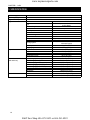
CONTENTS
CHAPTER 1. GENERAL INFORMATION ........................................................................................ 1-1
1. TRACTOR VIEW ............................................................................................................................................... 1-3
2. TIGHTENING TORQUE FOR STANDARD BOLTS AND NUTS ................................................................. 1-4
2.1 TIGHTENING TORQUE ........................................................................................................................ 1-4
3. SPECIFICATIONS ............................................................................................................................................ 1-6
4. IDENTIFICATIONS ........................................................................................................................................... 1-8
4.1 ENGINE NUMBER ................................................................................................................................ 1-8
4.2 SERIAL NUMBER OF THE TRACTOR ............................................................................................... 1-8
5. CAUTION BEFORE REPAIR .......................................................................................................................... 1-9
5.1 BEFORE REPAIR OR INSPECTION .................................................................................................. 1-9
5.2 ASSEMBLY AND DISASSEMBLY ......................................................................................................... 1-9
5.3 PARTS TO BE REPLACED .................................................................................................................. 1-9
5.4 PARTS ..................................................................................................................................................... 1-9
5.5 ASBESTOS PARTS ............................................................................................................................. 1-10
5.6 ELECTRICAL SYSTEM ....................................................................................................................... 1-10
5.7 TUBES AND RUBBERS ..................................................................................................................... 1-11
5.8 LUBRICANT ......................................................................................................................................... 1-11
6. REGULAR CHECK LIST ............................................................................................................................... 1-12
7. OIL & WATER SUPPLY LIST ........................................................................................................................ 1-13
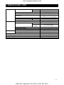
CHAPTER 2. ENGINE ........................................................................................................................ 2-1
1. GENERAL ......................................................................................................................................................... 2-3
1.1 APPEARANCE ....................................................................................................................................... 2-3
1.2 SPECIFICATIONS ................................................................................................................................. 2-4
1.3 PERFORMANCE CURVE ..................................................................................................................... 2-5
1.4 DIMENSIONS ......................................................................................................................................... 2-6
1.5 GENERAL WARNING ........................................................................................................................... 2-6
2. STRUCTURE AND FUNCTION ..................................................................................................................... 2-7
2.1 BODY ...................................................................................................................................................... 2-7
2.2 LUBRICATION SYSTEM ..................................................................................................................... 2-11
2.3 COOLING SYSTEM ............................................................................................................................. 2-13
2.4 FUEL SYSTEM ..................................................................................................................................... 2-15
2.5 INTAKE AND EXHAUST SYSTEM ...................................................................................................... 2-22
3. DISASSEMBLING AND SERVICING .......................................................................................................... 2-24
3.1 TROUBLIE SHOOTING ...................................................................................................................... 2-24
3.2 SERVICING SPECIFICATIONS ......................................................................................................... 2-27
3.3 CHECKING, DISASSEMBLING AND SERVICING .......................................................................... 2-33
K&T Saw Shop 606-678-9623 or 606-561-4983
www.mymowerparts.com
CHAPTER 3. CLUTCH ....................................................................................................................... 3-1
1. TROUBLE SHOOTING.................................................................................................................................... 3-3
2. SPECIFICATIONS,TIGHTENING TORQUES AND SPECIAL TOOLS ...................................................... 3-4
2.1 SPECIFICATIONS ................................................................................................................................. 3-4
2.2 TIGHTENING TORQUES ..................................................................................................................... 3-4
2.3 SPECIAL TOOLS ................................................................................................................................... 3-4
3. STRUCTURE AND OPERATION ................................................................................................................... 3-5
3.1 FEATURES ............................................................................................................................................. 3-5
3.2 STRUCTURE ......................................................................................................................................... 3-5
3.3 OPERATION ........................................................................................................................................... 3-6
4. PREPARATION STAGE FOR DISASSEMBLING AND ASSEMBLING ........................................................ 3-7
4.1 SEPARATING PANEL FRAME ASSEMBLY ......................................................................................... 3-7
4.2 SEPARATING ENGINE AND CLUTCH HOUSING CASE ................................................................. 3-9
4.3 DISASSEMBLY ..................................................................................................................................... 3-10
5. ADJUSTMENT OF PEDALS ......................................................................................................................... 3-11
5.1 DEFLECTION OF CLUTCH PEDAL ................................................................................................. 3-11
5.2 CLEARANCE BETWEEN SAFETY STARTING SWITCH AND LINK ............................................. 3-11
6. INSPECTION AND REPAIR .......................................................................................................................... 3-12
6.1 WEAR AND DAMAGE ON CLUTCH DISC ....................................................................................... 3-12
6.2 CLEARANCE BETWEEN SPLINE BOSS OF THE CLUTCH DISC AND
SHUTTLE SHAFT SPLINES .............................................................................................................. 3-12
6.3 FLATNESS OF CLUTCH PRESSURE PLATE, DAMAGES ............................................................ 3-13
6.4 DAMAGES TO FLYWHEEL, ADJUSTMENT OF RELEASE BEARING .......................................... 3-13
6.5 WEAR OR DAMAGES ON RELEASE BEARING, RELEASE FORK AND RELEASE HUB ........ 3-13
6.6 CLEARANCE BETWEEN CLUTCH PEDAL SHAFT AND CLUTCH PEDAL BUSHING ............ 3-14
CHAPTER 4. TRANSMISSION SYSTEM ........................................................................................ 4-1
1. TROUBLESHOOTING ..................................................................................................................................... 4-3
1.1 TROUBLESHOOTING FOR SHUTTLE SHIFT IN OPERATION ERROR ...................................... 4-3
1.2 TROUBLESHOOTING FOR MAIN SHIFTS IN OPERATION ERROR ............................................ 4-3
1.3 TROUBLESHOOTING FOR AUXILIARY AND CREEP SHIFTS IN OPERATION ERROR ........... 4-4
1.4 TROUBLESHOOTING FOR REAR DIFFERENTIAL GEAR IN OPERATION ERROR ................. 4-4
1.5 TROUBLESHOOTING FOR REAR DIFFERENTIAL IN OPERATION ERROR ............................. 4-4
1.6 TROUBLESHOOTING FOR FRONT WHEEL DRIVE IN OPERATION ERROR ........................... 4-5
1.7 TROUBLESHOOTING FOR PTO CLUTCH IN OPERATION ERROR ........................................... 4-5
1.8 TROUBLESHOOTING FOR PTO IN OPERATION ERROR ............................................................. 4-5
1.9 TROUBLESHOOTING FOR PARKING BRAKE IN OPERATION ERROR ...................................... 4-5
2. SPECIFICATIONS ............................................................................................................................................ 4-6
2.1 TIGHTENING TORQUES ..................................................................................................................... 4-6
3. STRUCTURE ................................................................................................................................................... 4-7
3.1 POWER TRAIN DIAGRAM .................................................................................................................... 4-7
3.2 STRUCTURE ......................................................................................................................................... 4-8
K&T Saw Shop 606-678-9623 or 606-561-4983
www.mymowerparts.com
3.3 POWER TRAIN ...................................................................................................................................... 4-9
3.3.1 TRANSMISSION ......................................................................................................................... 4-9
3.3.2 SHUTTLE SHIFT SECTION ................................................................................................... 4-10
3.3.3 MAIN SHIFT .............................................................................................................................. 4-11
3.3.4 AUXILIARY SHIFT .................................................................................................................... 4-12
3.3.5 FRONT WHEEL DRIVE ........................................................................................................... 4-12
3.3.6 PTO SHIFT ................................................................................................................................ 4-13
3.4 OPERATION ......................................................................................................................................... 4-14
3.4.1 FEATURES ................................................................................................................................. 4-14
4. PREPARATION STAGE FOR DISASSEMBLING AND ASSEMBLING TRANSMISSION ........................ 4-22
4.1 DRAINING THE TRANSMISSION FLUID ......................................................................................... 4-22
4.2 SEPARATING PANEL FRAME ASSEMBLY ....................................................................................... 4-23
4.3 SEPARATING REAR FENDERS AND PLATFORM ASSEMBLY ..................................................... 4-25
5. TO DISMANTLE AND TO ASSEMBLE ......................................................................................................... 4-28
5.1 STANDARD TABLE FOR REPAIR ..................................................................................................... 4-28
5.2 TO DISMANTLE AND TO ASSEMBLE ............................................................................................... 4-28
6. DIFFERENTIAL GEAR ................................................................................................................................... 4-55
6.1 STRUCTURE ....................................................................................................................................... 4-55
6.2 OPERATION ......................................................................................................................................... 4-56
6.3 LOCKING OF THE DIFFERENTIAL GEAR ...................................................................................... 4-57
CHAPTER 5. FRONT AXLE ............................................................................................................... 5-1
1. TROUBLESHOOTING ..................................................................................................................................... 5-3
2. SPECIFICATIONS ............................................................................................................................................ 5-4
3. STRUCTURE ................................................................................................................................................... 5-6
3.1 OPERATION ........................................................................................................................................... 5-6
3.2 FRONT WHEEL ALIGNMENT .............................................................................................................. 5-7
3.3 TOE-IN ADJUSTMENT .......................................................................................................................... 5-8
3.4 DIRECTION CONTROL ANGLE FOR THE FRONT WHEEL .......................................................... 5-8
3.5 ROCKING FORCE OF THE FRONT AXLE, DEFLECTION IN FRONT & REAR DIRECTIONS .. 5-9
4. PREPARATION STAGE FOR DISASSEMBLING AND ASSEMBLING ...................................................... 5-10
4.1 SEPARATING FRONT AXLE .............................................................................................................. 5-10
5. TO DISMANTLE AND TO ASSEMBLE ......................................................................................................... 5-12
5.1 FRONT AXLE CASE AND FRONT AXLE ........................................................................................... 5-12
5.2 BEVEL GEAR CASE AND FRONT AXLE CASE .............................................................................. 5-13
5.3 BEVEL GEAR CASE AND FRONT AXLE SUPPORT ...................................................................... 5-14
5.4 FRONT AXLE SUPPORT AND DIFFERENTIAL GEAR CASE ....................................................... 5-15
5.5 FRONT DIFFERENTIAL GEAR ......................................................................................................... 5-16
5.6 FRONT BRACKET .............................................................................................................................. 5-19
5.7 REAR BRACKET ................................................................................................................................. 5-20
K&T Saw Shop 606-678-9623 or 606-561-4983
www.mymowerparts.com
CHAPTER 6. HYDRAULIC SYSTEMS ............................................................................................. 6-1
1. HYDRAULIC LIFT SYSTEM ............................................................................................................................ 6-3
1.1 TROUBLE SHOOTING ......................................................................................................................... 6-5
1.2 SPECIFICATIONS ................................................................................................................................. 6-6
1.3 STRUCTURE AND OPERATION ......................................................................................................... 6-9
1.4 PREPARATION STAGE FOR DISASSEMBLING AND ASSEMBLING ........................................... 6-25
1.5 DISMANTLE AND ASSEMBLING ....................................................................................................... 6-27
2.
PTO CLUTCH VALVE SYSTEM .................................................................................................................. 6-38
2.1 SPECIFICATIONS AND DIAGRAM .................................................................................................... 6-38
2.2 STRUCTURE AND OPERATION ....................................................................................................... 6-39
2.3 ASSEMBLING AND DISASSEMBLING ............................................................................................. 6-44
2.4 TO CHECK AND TO REPAIR ............................................................................................................. 6-46
3. POWER STEERING SYSTEM ...................................................................................................................... 6-47
3.1 TROUBLE SHOOTING......................................................................................................................... 6-47
3.2 INTRODUCTION ................................................................................................................................. 6-48
3.3 STRUCTURE AND OPERATION ....................................................................................................... 6-50
3.4 PREPARATION STAGE FOR DISASSEMBLING AND ASSEMBLING ........................................... 6-55
3.5 TO DISMANTLE AND TO ASSEMBLE ............................................................................................... 6-58
4. HYDRAULIC PUMP ....................................................................................................................................... 6-66
4.1 TROUBLESHOOTING ........................................................................................................................ 6-66
4.2 SPECIFICATIONS ............................................................................................................................... 6-66
4.3 STRUCTURE AND OPERATION ....................................................................................................... 6-67
4.4 TO DISMANTLE AND TO ASSEMBLE ............................................................................................... 6-69
5. HYDRAULIC FILTER ..................................................................................................................................... 6-71
5.1 STRUCTURE AND OPERATION ....................................................................................................... 6-71
6. HYDRAULIC PRESSURE OPERATION PRINCIPLE AND TROUBLE SHOOTING ............................. 6-73
6.1 COMPOSITION OF HYDRAULIC DEVICE & FLOW DIAGRAM OF HYDRAULIC OIL ................ 6-73
6.2 STEERING DEVICES ......................................................................................................................... 6-75
6.3 PTO SYSTEM ....................................................................................................................................... 6-77
6.4 HYDRAULIC PRESSURE RISE & FALL DEVICE ........................................................................... 6-79
CHAPTER 7. BRAKE .......................................................................................................................... 7-1
1. TROUBLESHOOTING ..................................................................................................................................... 7-3
2. SPECIFICATIONS ............................................................................................................................................ 7-3
3. TIGHTENING TORQUE .................................................................................................................................. 7-4
4. STRUCTURE AND OPERATION ................................................................................................................... 7-5
4.1 STRUCTURE ......................................................................................................................................... 7-5
4.2 OPERATION ........................................................................................................................................... 7-7
5. DISASSEMBLING AND ASSEMBLING .......................................................................................................... 7-8
5.1 DRAINING THE TRANSMISSION FLUID ........................................................................................... 7-8
5.2 SEPARATING PANEL FRAME ASSEMBLY ......................................................................................... 7-9
K&T Saw Shop 606-678-9623 or 606-561-4983
www.mymowerparts.com
5.3 SEPARATING REAR FENDERS AND PLATFORM ASSEMBLY ..................................................... 7-11
5.4 DISASSEMBLING REAR AXLE CASE .............................................................................................. 7-14
5.5 DISASSEMBLING BRAKE CASE ...................................................................................................... 7-15
6. ADJUSTMENT OF THE BRAKE ................................................................................................................... 7-16
7. SERVICING .................................................................................................................................................... 7-17
CHAPTER 8 ELECTRIC SYSTEM .................................................................................................... 8-1
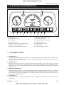
1. ELECTRONIC INSTRUMENTATION ............................................................................................................. 8-3
1.1 INSTRUMENT GAUGE ............................................................................................................................ 8-3
1.2 INDICATORS AND WARNING LIGHTS ................................................................................................. 8-4
2. TROUBEL SHOOTING .................................................................................................................................... 8-6
3. SERVICING SPECIFICATIONS ..................................................................................................................... 8-8
4. MECHANISM ..................................................................................................................................................... 8-9
4.1 STARTING SYSTEM ................................................................................................................................ 8-9
4.2 CHARGING SYSTEM ............................................................................................................................. 8-12
4.3 PREHEATING SYSTEM ......................................................................................................................... 8-14
4.4 FUSE ....................................................................................................................................................... 8-15
4.5 GAUGE AND SENSORS ....................................................................................................................... 8-16
CHAPTER 9. CABIN SYSTEM ......................................................................................................... 9-1
1. DISASSEMBLY AND ASSEMBLY .................................................................................................................... 9-3
2. HEATER ............................................................................................................................................................ 9-8
2.1 STRUCTURE ......................................................................................................................................... 9-8
2.2 DISASSEMBLY AND ASSEMBLY ......................................................................................................... 9-8
2.3 HEATER OPERATION DEVICE ........................................................................................................... 9-8
3. AIR CONDITIONER ......................................................................................................................................... 9-9
3.1 AIR CONDITIONER .............................................................................................................................. 9-9
3.2 TROUBLE SHOOTING ....................................................................................................................... 9-13
K&T Saw Shop 606-678-9623 or 606-561-4983
www.mymowerparts.com
K&T Saw Shop 606-678-9623 or 606-561-4983
www.mymowerparts.com
CHAPTER 1
GENERAL INFORMATION
K&T Saw Shop 606-678-9623 or 606-561-4983
www.mymowerparts.com
K&T Saw Shop 606-678-9623 or 606-561-4983
www.mymowerparts.com
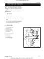
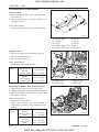
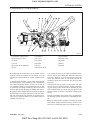
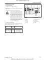
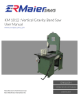
GENERAL INFORMATION
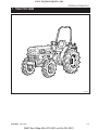
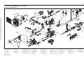
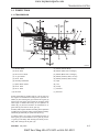
1. TRACTOR VIEW
569W101A
D569-W02 May-2003
K&T Saw Shop 606-678-9623 or 606-561-4983
1-3
www.mymowerparts.com
CHAPTER 1
8454
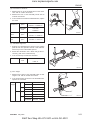
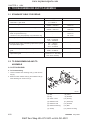
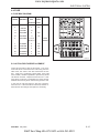
2. TIGHTENING TORQUE FOR STANDARD BOLTS AND NUTS
2.1 TIGHTENING TORQUE
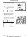
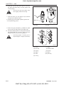
Screws, bolts and nuts whose tightening torques are not specified in this workshop manual should be tightened
according to the table below.
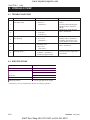
A. TIGHTENING TORQUE FOR STANDARD BOLTS AND NUTS
Grade
No grade 4T
Unit
Nominal
Diameter
M6
(6 mm, 0.24 in.)
M8
(8 mm, 0.31 in.)
M 10
(10 mm, 0.39 in.)
M 12
(12 mm, 0.47 in.)
M 14
(14 mm, 0.55 in.)
M 16
(16 mm, 0.63 in.)
M 18
(18 mm, 0.71 in.)
M 20
(20 mm, 0.79 in.)
4
7T
9T
7
9
N·m
Kgf·m
lbf·ft
N·m
Kgf·m
lbf·ft
N·m
Kgf·m
lbf·ft
7.85
0.80
5.79
9.80
1.00
7.24
12.3
1.25
9.1
~
~
~
~
~
~
~
~
~
9.30
0.95
6.87
11.2
1.15
8.32
14.2
1.45
10.5
17.7
1.8
13.0
23.6
2.4
17.4
29.4
3.0
21.7
~
~
~
~
~
~
~
~
~
20.5
2.1
15.2
27.4
2.8
20.2
34.3
3.5
25.3
39.2
4.0
29.0
48.1
4.9
35.5
60.8
6.2
44.9
~
~
~
~
~
~
~
~
~
45.0
4.6
33.2
55.8
5.7
41.2
70.5
7.2
52.1
62.8
6.4
46.3
77.5
7.9
57.2
103
10.5
76.0
~
~
~
~
~
~
~
~
~
72.5
7.4
53.5
90.1
9.2
66.5
117
12.0
86.8
108
11.0
79.6
124
12.6
91.2
167
17.0
123
~
~
~
~
~
~
~
~
~
125
12.8
92.5
147
15.0
108
196
20.2
144
167
17.0
123
196
20.0
145
260
26.5
192
~
~
~
~
~
~
~
~
~
191
19.5
141
225
23.0
166
303
31.0
224
245
25.0
181
275
28.0
203
343
35.0
254
~
~
~
~
~
~
~
~
~
284
29.0
210
318
32.5
235
401
41.0
297
334
34.0
246
368
37.5
272
490
50.0
362
~
~
~
~
~
~
~
~
~
392
40.0
289
431
44.0
318
568
58.0
420
* The figures on the table above are indicated the top of screw of bolt.
1-4
D569-W02 May-2003
K&T Saw Shop 606-678-9623 or 606-561-4983
www.mymowerparts.com
GENERAL INFORMATION
B. TIGHTENING TORQUE FOR STUDS
M8
11.7 to 15.7 N·m
1.2 to 1.6 kgf·m
8.6 to 11.5 lbf·ft
M10
24.5 to 31.4 N·m
2.5 to 3.2 kgf·m
18.0 to 23.1 lbf·ft
M12
34.3 to 49.0 N·m
3.4 to 5.0 kgf·m
25.3 to 36.1 lbf·ft
C. TIGHTENING TORQUE FOR HIGH PRESSURE HOSE UNION NUTS
Hose Size
(Inside Diameter: Inches)
1/8″
3/16″
1/4″
5/16″
3/8″
1/2″
5/8″, 3/4″
1″
Screw Size (PF)
1/8″
1/4″
1/4″
3/8″
3/8″
1/2″
3/4″
1″
Tightening (N·m)
9.8
24.5
24.5
49.0
49.0
58.8
117.7
137.3
1
2.5
2.5
5
5
6
12
14
7.2
18.0
18.0
36.1
36.1
43.3
86.8
101.2
Torque
(kgf·m)
(lbf·ft)
D569-W02 May-2003
K&T Saw Shop 606-678-9623 or 606-561-4983
1-5
www.mymowerparts.com
CHAPTER 1 8454
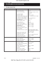
3. SPECIFICATION
MODEL
Maximum PTO power
Engine GROSS power
Engine
8454
Model
Type
Number of cylinders
Bore and stroke
Total displacement
Rated revolution
Injection timing
Injection order
Compression ratio
Lubricating system
Cooling system
Capacities
Dimensions
(with std.tires)
Track width
Alternator
Weight (Dry)
Fuel tank
Engine crankcase
Engine coolant
Transmission case
Front axle case
Overall length (without 3p)
Overall length (with 3p)
Overall Length (minimum tread)
Overall height (Top of ROPS)
Overall height (Top of CABIN)
Overall height (Top of steering wheel)
Wheelbase
Ground clearance
Front
Rear
38 HP
45 HP
4A220
Indirect injection, vertical, water-cooled,
4cycle diesel
4
87 x 92.4 (3.425 x 3.638in.)
2,197
2,600 RPM
18 before T.D.C.
1-3-4-2
22:01
Forced lubrication by trochoida pump
Pressurized radiator, Forced circulation
with water pump
12V, 50 AMPS
207 kg (456lb)
40 L (10.6 gal.)
7.0 L (1.9 gal.)
8.9 L (2.4 gal.)
34.0 L (9.0 gal.)
8.2 L (2.2 gal.)
3,073mm (120.9 in.)
3,323mm (130.8 in.)
1,550mm (61.0 in.)
2,235 mm (88.0 in.)
2,337 mm (92.0 in.)
1,610 mm (63.3 in.)
1,820 mm (71.6 in.)
370 mm (14.5 in.)
1,265 mm (49.8 in)
1,180 - 1,490mm (46.4 - 58.6 in.)
1-6
K&T Saw Shop 606-678-9623 or 606-561-4983
www.mymowerparts.com
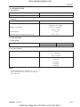
3. SPECIFICATION CON'T
Drive system
Tire size (Std. Tires)
Front
Rear
Clutch
Steering
Transmission
Brake
Hydraulic system
Differential
Hydraulic lift control system
Pump Capacity
Travel
Parking
Main Pump
Power steering
pump
Three point hitch
Maximum lifting capacity
No. of remote control valve ports (option)
PTO
PTO shaft
Revolution (independent PTO)
Min. turning radius ( without Brake)
Traction system
Weight (with ROPS)
Traveling speed ( at rated engine speed with Std tires)
9.5 - 16.6
14.9 - 24.8
Dry single disc
Hydrostatic steering system
Synchronized shuttle
12 forward and 12 reverse speeds
Wet disc type
Connected with the traveling brake
Bevel gear
Position, Draft and Mix control
31.2 L/min (8.2 gal.)
18.7 L/min (5.0 gal.)
SAE Category 1 & 2
1,800 kg (3,968 lb)
2-4
SEA 1 3/8, 6 splines
560 rpm
2,865 mm (112.7 in.)
Fixed drawer (or swing drawer Option)
1,720 kg (3,792 lb)
0.37 - 24.6 km/h (0.23 - 15.29 mph)
1-7
K&T Saw Shop 606-678-9623 or 606-561-4983
www.mymowerparts.com
CHAPTER 1
8454
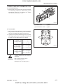
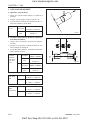
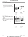
4. IDENTIFICATION
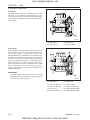
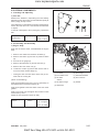
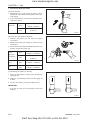
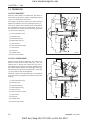
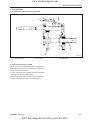
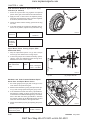
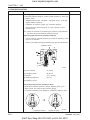
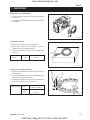
4.1 ENGINE NUMBER
Engine number is engraved in the left side of the cylinder block as shown in the figure.Engine number fills
the important role of providing it’s record.
569W103A
(1) Engine Serial Number
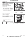
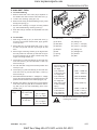
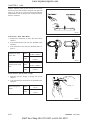
4.2 SERIAL NUMBER OF THE
TRACTOR
Serial number of the tractor is stamped on the left side
of the front axle frame as shown in the figure.
569W104A
(1) Tractor Serial Number
(2) Transmission Serial Number
1-8
D569-W02 May-2003
K&T Saw Shop 606-678-9623 or 606-561-4983
www.mymowerparts.com
GENERAL INFORMATION
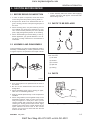
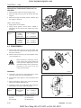
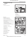
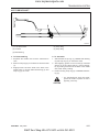
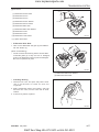
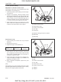
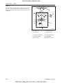
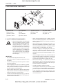
5. CAUTION BEFORE REPAIR
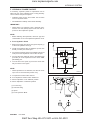
5.1 BEFORE REPAIR OR INSPECTION
1. In case of repair or inspection, locate the tractor
on the flat ground and pull the parking brake on.
2. Except for the items to be checked while the engine is running, be sure to stop the engine prior to
the work.
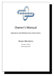
7. Finish assembly within 20 minutes after applying
sealant, after that, wait approx. 30 minutes later
before filling with oil.
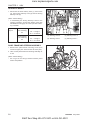
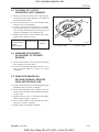
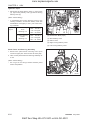
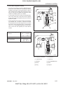
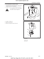
5.3 PARTS TO BE REPLACED
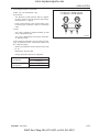
3. When washing parts, use parts washing solvent
for industrial use (avoid using gasoline so to prevent environmental pollution). For the hydraulic
parts, apply designated hydraulic oil in washing.
4. When disassembling and assembling of the hydraulic apparatus, pay special attention not to allow dust or foreign substance to be attached or
intermixed.
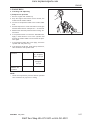
5.2 ASSEMBLY AND DISASSEMBLY
To check a failure, try to find out its underlying cause. If
assembly or disassembly is needed, perform the work
in regular sequence as specified in this repair manual.
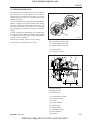
569W106A
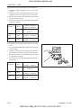
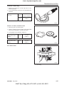
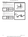
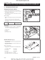
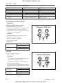
The following parts should be replaced with new ones
when removed.
(1) Oil Seal
(2) Gasket
(3) Lock Nut
(4) Split Pin
(5) O-Ring
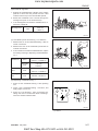
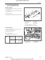
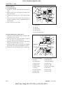
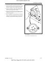
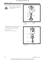
5.4 PARTS
227W105A
1. Disassembled parts shall be arranged orderly.
2. Sort out the parts to be replaced from the ones to
be reused.
CC
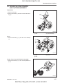
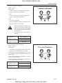
3. Be sure to use standard bolts and nuts that are
designated.
4. When assembling snap rings or spring pin types,
take care of assembling direction.
5. Split pin shall be spread surely not to escape when
installed.
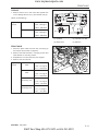
6. When using sealant (such as gasket bond) on the
assembled surfaces, apply it evenly and consistently in a height of 3 ~ 5 mm (0.12 ~ 0.2 in.) on the
contact surface after removing the old bond and
cleaning the sealing surface with solvent. Apply
sealant on the center of the contact surface for the
space between the bolt holes of the contact
surface, and on the more inner side than the bolt
hole for the bolt area.
569W107A
When replacing part only genuine Cub Cadet parts.
D569-W02 May-2003
K&T Saw Shop 606-678-9623 or 606-561-4983
1-9
www.mymowerparts.com
CHAPTER 1
8454
5.5 ASBESTOS PARTS
Since dust out of asbestos fibrous parts is extremely
dangerous to your health, be sure to clean such parts
carefully, do not use compressed air.
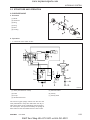
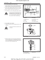
5.6 ELECTRICAL SYSTEM
1. Check electrical wiring every year for any damage
or short circuit at the connections. In addition, have
your dealer inspection the electric system regularly.
2. Do not modify or reorganize the wiring of the electric field parts.
3. When disconnecting the battery cable, disconnect
negative cable first, reinstall the positive cable first
when reinstalling.
569W109A
5. When connecting the connector, insert it until it
snaps.
Disconnect battery negative terminal
•
Be sure to turn the starting key OFF
when connecting or disconnecting the
cable.
CAUTION
569W110A
6. Be sure not to drop sensors and relays which are
fragile.
7. When replacing a broken fuse with a new one, be
sure to use the fuse of capacity as specified.
569W108A
4. Remove the connector by pulling the plastic
section, not the wiring.
1-10
D569-W02 May-2003
K&T Saw Shop 606-678-9623 or 606-561-4983
www.mymowerparts.com
GENERAL INFORMATION
5.7 TUBES AND RUBBERS
5.8 LUBRICANT
569W111A
Be cautious of oil or other petroleum products on the
hoses and rubber parts, this may cause damage.
569W112A
When assembling and fixing, apply designated lubricant where specified in accordance with this repair
manual.
D569-W02 May-2003
K&T Saw Shop 606-678-9623 or 606-561-4983
1-11
www.mymowerparts.com
CHAPTER 1
8454
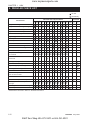
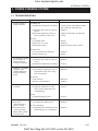
6. REGULAR CHECK LIST
the first
periodically
Since
Purchased
Indicated Hours By Hour Meter
Check Items
50 100 150 200 250 300 350 400 450 500 600 700 800 1500hr
1yr
2yr
Engine oil change
Engine oil filter cartridge change
Transmission oil change
Hydraulic oil filter change
Front axle oil change
Applying grease
Clutch pedal deflection
Brake pedal deflection
Fan belt tension
Fuel filter element change
Air cleaner element change
Battery electrolyte
Oil pressure fuel pipe’s inlet screw
if loosened
Radiator hose’s inlet bands if
loosened
Fuel pipe change
Radiator hose change
Hydraulic pipe joint change
Steering hose change
Toe-in
Deflection adjustment in front and
rear of the front axle
Direction control section
Bolt, nuts and pins of each part
Battery positive code adjustment &
change
Bleeding water in clutch housing
Check injection nozzle*
* Maintenance intervals in basis on the EPA instructions.
1-12
D569-W02 May-2003
K&T Saw Shop 606-678-9623 or 606-561-4983
www.mymowerparts.com
GENERAL INFORMATION
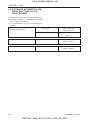
7. OIL & WATER SUPPLY LIST
Supply Items
Fuel
Capacity
(42.3 U.S.gal.)
40
Recommended Spec.
No. 2 - D diesel fuel
No. 1 - D diesel fuel if temperature
is below - 10 °C (14 °F)
Coolant
8.9
(2.4 U.S.gal.)
Fresh clean water with antifreeze
Engine oil
7.0
(1.8 U.S.gal.)
SAE 15 W - 40
Transmission oil
34
(9.0 U.S.gal.)
Universal tractor/transmission
Front axle section
8.2
(2.2 U.S.gal.)
hydraulic oil
Applying
grease
Hydraulic control lever
shaft section
3 point link section
Small quantity
SAE multi-purpose type grease
Until grease exits
Brake pedal link section
Bracket section in front
and rear of the front axle
Clutch release hub
Supply when removed
D569-W02 May-2003
K&T Saw Shop 606-678-9623 or 606-561-4983
1-13
www.mymowerparts.com
K&T Saw Shop 606-678-9623 or 606-561-4983
www.mymowerparts.com
CHAPTER 2
ENGINE
K&T Saw Shop 606-678-9623 or 606-561-4983
www.mymowerparts.com
K&T Saw Shop 606-678-9623 or 606-561-4983
www.mymowerparts.com
ENGINE
1. GENERAL
1.1 APPEARANCE
569W201A
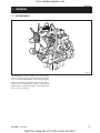
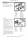
The DAEDONG A series engines are vertical, watercooled, 4-cycle, three or four cylinders diesel engines,
they concentrate DAEDONG’s foremost technologies.
With swirl combustion chamber, bosch K type fuel injection pump, well-balanced designs, they feature
greater power, low fuel consumption, less vibration and
noise, and low emission.
D569-W02 May-2003
K&T Saw Shop 606-678-9623 or 606-561-4983
2-3
www.mymowerparts.com
CHAPTER 2
8454
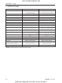
1.2 SPECIFICATIONS
MODEL
Type
Number of cylinder
Bore and stroke mm (in.)
3
Total displacement cc (in .)
4A220
4A200T
Vertical, water-cooled,
Vertical, water-cooled,
4-cycle diesel engine
4-cycle diesel engine (Turbo)
4
4
87.0 x 92.4 (3.43 x 3.64)
83.0 x 92.4 (3.27 x 3.64)
2,197(134.1 )
1,999(122.0)
vortex chamber
vortex chamber
43/2,700 (30.9/2,700)
47/2,600 (34.6/2,600)
Maximum idling speed rpm
2,900
2,800
Minimum idling speed rpm
850 ~ 900
850 ~ 900
1-3-4-2
1-3-4-2
Counterclockwise
Counterclockwise
(viewed from flywheel side)
(viewed from flywheel side)
Bosch K TYPE mini pump
Bosch K TYPE mini pump
Combustion chamber
POWER (NET) PS/rpm (kW. rpm)
Order of firing
Direction of rotation
Injection pump
2
Injection pressure
Injection timing (Before T.D.C)
Compression ratio
Fuel
Lubricant
Dimensions mm
(length x width x height) (in.)
Dry weight kg (kg, lbs.)
140 ~ 150 kgf/cm
140 ~ 150 kgf/cm2
(13.73 ~ 14.71 MPa, 1991 ~ 2133 psi)
(13.73 ~ 14.71 MPa, 1991 ~ 2134 psi)
18°
12°
22 : 1
22 : 1
Diesel fuel
Diesel fuel
Engine oil SAE 15W-40
Engine oil SAE 15W-40
817.3 x 488.1 x 735.8
817.3 x 542.0 x 735.8
(32.2 x 19.2 x 29.0)
(32.2 x 19.2 x 29.0)
207 (456)
211 (465)
* NOTE: Change of parts are not subject to advance notice.
2-4
D569-W02 May-2003
K&T Saw Shop 606-678-9623 or 606-561-4983
www.mymowerparts.com
ENGINE
1.3 PERFORMANCE CURVE
569W204A
D569-W02 May-2003
K&T Saw Shop 606-678-9623 or 606-561-4983
569W203A
2-5
www.mymowerparts.com
CHAPTER 2
8454
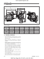
1.4 DIMENSIONS
569W205A
Sample/td Spec.
mm (in.)
A
B
C
D
E
F
4A220
697.3 (27.45)
817.3 (32.18)
280 (11.02)
φ 400 (15.75)
502.6 (19.79)
262.5 (10.33)
4A200T
697.3 (27.45)
817.3 (32.18)
280 (11.02)
φ 400 (15.75)
519 (20.43)
282.4 (11.12)
G
H
I
J
K
L
4A220
736 (28.98)
260 (10.24)
240 (9.45)
φ 321 (12.64)
104.5 (4.11)
-
4A200T
736 (28.98)
260 (10.24)
240 (9.45)
φ 321 (12.64)
104 (4.09)
542 (21.34)
1.5 GENERAL WARNING
•
When disassembling, arrange each part on a clean
place. Do not mix them up. Replace bolts and nuts
where they were.
•
When connecting instruments to electrical
equipment, first disconnect battery negative
terminal.
•
Replace gaskets or O-rings with new ones when
reassembling, and apply grease on a O-rings and
the oil seals when reassembling.
•
When exchanging parts, use genuine DAEDONG
parts to maintain engine performance and safety.
•
To prevent oil and water leakage, apply non-drying
adhesive to the gaskets according to this manual
before reassembling.
•
When hoisting up the engine, use the hook provided on the cylinder head.
•
When installing the engine, use the hook provided
on the cylinder head.
•
When installing external cir-clips or internal cir-clips,
direct corner end to the non- loosening direction.
2-6
D569-W02 May-2003
K&T Saw Shop 606-678-9623 or 606-561-4983
www.mymowerparts.com
ENGINE
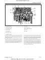
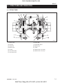
2. STRUCTURE AND FUNCTION
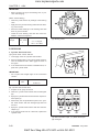
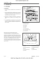
2.1 BODY
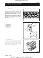
A. CYLINDER HEAD
The cylinder head is made of special alloy cast iron
which can resist high temperature and pressure
caused by combustion. The intake and exhaust ports
are arranged cross-flow type to get high combustion
efficiency by protecting the suction air from being heated
and expanded by heated exhaust air.
The Daedong vortex type combustion chamber is designed for high efficiency combustion and reducing fuel
consumption. The glow plugs assures easy engine
starts even at (-) 15 °C (5 °F).
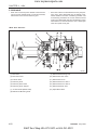
569W206A
(1) Combustion Chamber
(2) Inlet Port
(3) Exhaust Port
(4) Injection Nozzle
(5) Glow Plug
(6) Cylinder Head
569W207A
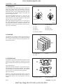
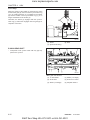
B. CYLINDER BLOCK
The engine has a high durability tunnel-type cylinder
block. Furthermore, liner less type, allows effective cooling, less distortion, and greater wear-resistance using
special material. The noise is reduced to a minimum
because each cylinder had its chamber.
569W208A
D569-W02 May-2003
K&T Saw Shop 606-678-9623 or 606-561-4983
2-7
www.mymowerparts.com
CHAPTER 2
8454
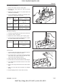
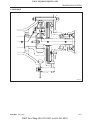
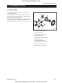
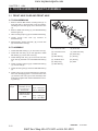
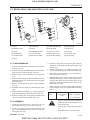
C. CRANKSHAFT
The crankshaft is made of forged steel and the journals,
the crankpins and the bearing surface for the oil seal
are induction-hardened to increase wear resistance.
Each crankshaft journal is supported by the main bearing case (3) having a bearing inside.
The front crankshaft bearing (2) is a solid type bushing
and rear and intermediate bearings are a split type.
The crankshaft’s bearings have oil holes for lubricant
flow.
569W209A
(1) Crankshaft
(4) Crankshaft Bearing 2
(2) Crankshaft Bearing
(5) Thrust Bearing
(3) Main Bearing Case
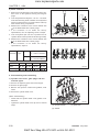
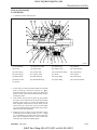
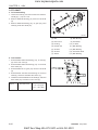
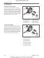
D. PISTON AND PISTON RINGS
The piston are made of an aluminum alloy which is
temperature and pressure resistant. Three rings installed in grooves of the piston. The top ring (1) is a
keystone type, which can withstand heavy loads, and
the barrel face on the ring fits well to the cylinder wall.
The second ring (2) is an undercut type, which prevents the oil from being carried up. The oil ring (3) has
chambered contact faces and an expander ring, which
increase the pressure of the oil ring against the cylinder wall to scrape the oil. The top ring is plated with
hard chrome to increase wear resistance (The ring of
4A200T engine is mode of a special steel).
569W210A
(1) Top Ring
(3) Oil Ring
(2) Second Ring
E. CONNECTING ROD
The connecting rod (2), which converts the reciprocating motion of the pistons caused by the fuel combustion into the rotating motion of the crankshaft, is made
of harden forged steel. The connecting rod has bearings at both ends. The small end has a solid type bearing (small end bushing (2)) and the big end has a split
type bearing (crankpin bearing (3)).
569W211A
(1) Small End Bushing
(3) Crankpin Bearing
(2) Connecting Rod
2-8
D569-W02 May-2003
K&T Saw Shop 606-678-9623 or 606-561-4983
www.mymowerparts.com
ENGINE
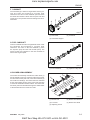
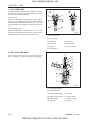
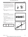
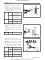
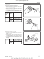
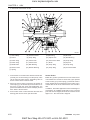
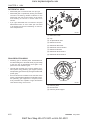
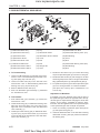
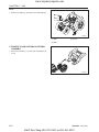
F. CAMSHAFT
The camshaft (3) is made of forged steel and it’s journals and cams are hardened to increase wear
resistance. The cams on the camshaft open and close
the intake and exhaust valves with the push rods and
rocker arms. The journals and their bearings are forcelubricated.
569W212A
(1) Cam Gear
(3) Camshaft
(2) Camshaft Stopper
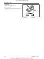
G. FUEL CAMSHAFT
This fuel camshaft is made of forged steel and its cams
are hardened and tempered to increase wear
resistance. The cams on the fuel camshaft (1) drive
the injection pump and the fuel transfer pump. The
governor balls are installed on the fuel camshaft to
control the engine speed.
569W213A
(1) Fuel Camshaft
(2) Injection Pump Gear
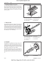
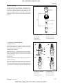
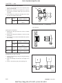
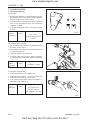
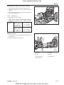
H. ROCKER ARM ASSEMBLY
The rocker arm assembly includes the rocker arms (1)
and an adjusting screw (3), which is at the end of rocker
arm and rests on the push rod, rocker arm brackets (4)
and rocker arm shaft (5). The rocker arms are activated
by the reciprocating motion of the push rods and open
or close the intake and exhaust valves. The rocker arm
and other parts are lubricated through the drilled holes
of the brackets and the rocker arm shaft.
569W214A
(1) Rocker Arm
(4) Rocker Arm Bracket
(2) Lock Nut
(5) Rocker Arm Shaft
(3) Adjusting Screw
D569-W02 May-2003
K&T Saw Shop 606-678-9623 or 606-561-4983
2-9
www.mymowerparts.com
CHAPTER 2
8454
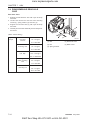
I. INTAKE AND EXHAUST VALVES
The valve and its guide of the intake are different from
those for the exhaust. Other parts, such as the spring,
spring retainers, valve spring collets, valve stem seals
are the same for both the intake and the exhaust. All
contact or sliding surfaces are hardened to increase
wear resistance.
569W215A
(1) Valve Spring Collet
(4) Valve Stem Seal
(2) Valve Spring Retainer (5) Exhaust Valve
(3) Valve Spring
(6) Intake Valve
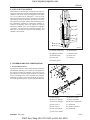
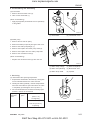
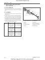
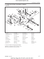
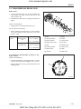
J. TIMING GEARS
The crankshaft drives the oil pump and the idle gear
engaged fuel camshaft and camshaft. The timing for
opening and closing the valves is extremely important
to achieve effective air intake and sufficient gas exhaust.
The appropriate timing can be obtained by aligning the
mark on the crankshaft gear (6) with one the idle gear
(5), idle gear with camshaft gear, idle gear with injection pump gear, when assembling.
569W216A
(1) Injection Pump Gear
(5) Idle Gear
(2) Fuel Camshaft
(6) Crankshaft Gear
(3) Camshaft Gear
(7) Crankshaft
(4) Camshaft
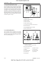
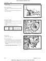
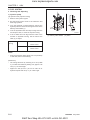
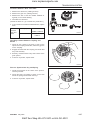
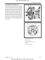
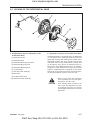
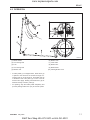
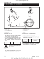
K. FLYWHEEL
The flywheel is installed on the rear end of the
crankshaft. Its inertia keeps the engine turning at a
constant speed, while the crankshaft tends to speed
up during the power stroke and to slow down during
other stokes. The flywheel has a ring gear (1), which
meshes with the drive pinion of the starter.
The flywheel has marks “TC” and “FI” on its outer rim.
The mark TC shows the piston’s top dead center and
the mark FI shows the fuel injection timing, when they
are aligned with the mark of window on the clutch housing.
569W217A
(1) Ring Gear
(3) Crankshaft
(2) Flywheel
2-10
D569-W02 May-2003
K&T Saw Shop 606-678-9623 or 606-561-4983
www.mymowerparts.com
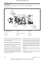
ENGINE
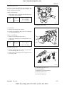
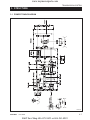
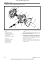
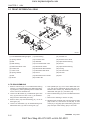
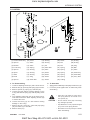
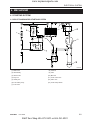
2.2 LUBRICATING SYSTEM
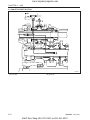
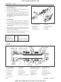
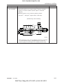
A. FLOW OF LUBRICATING OIL
The lubricating oil is forced to each journal through the
oil passages of the cylinder block, cylinder head and
shafts. The oil, splashed by the crankshaft or thrown
off from the bearings, lubricates other engine parts
such as the push rods (11), tappets (12), piston pins
and timing gears.
569W218A
(1) Piston
(9) Rocker Arm Shaft
(2) Idle Gear
(10) Rocker Arm
(3) Oil Pump
(11) Push Rod
(4) Relief Valve
(12) Tappet
(5) Strainer
(13) Oil Pressure Switch
(6) Oil Filter Element
(14) Camshaft
(7) Bypass Valve
(15) Crankshaft
(8) Oil Pan
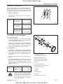
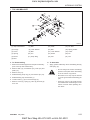
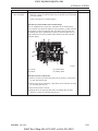
B. OIL PUMP
The oil pump is a gear type. Whose rotors have trochoid lobes. The inner rotor (3) has 4 lobes and the
outer rotor (4) has 5 lobes, and they are eccentrically
engaged to each other. The inner rotor, which is driven
by the crankshaft through the gears, rotates the outer
rotor in the same direction, varying the space between
the lobes.
While the rotors rotate from (A) to (B), the space leading to the inlet port increases, which causes the oil to
flow through the inlet port. When the rotors rotate to
(C), the port to which the space leads is changed from
inlet to outlet. At (D), the space decreases and oil is
discharged though the outlet port.
569W219A
(1) Inlet
(3) Inner Rotor
(2) Outlet
(4) Outer Rotor
D569-W02 May-2003
K&T Saw Shop 606-678-9623 or 606-561-4983
2-11
www.mymowerparts.com
CHAPTER 2
8454
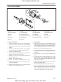
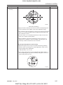
C. OIL FILTER AND RELIEF VALVE
The lubricating oil force-fed by the pump is filtered by
the filter cartridge, passing through the filter element
from the outside to the inside. When the filter element
accumulates dirt and the pressure difference between
the inside and the outside rises more than 98 kPa
(1.0 kgf/cm 2, 14 psi), the bypass valve (1) opens to
allow the oil to flow from the inlet line to outlet line,
bypassing the filter element. The relief valve ball (4) in
the inlet line allows oil to prevent damage to the lubricating system, when the oil pressure rises more than
441 kPa (4.5 kgf/cm2, 64 psi).
569W220A
(1) Bypass Valve
(2) Bypass Adjusting Spring
(3) Filter Element
(4) Relief Valve Ball
(5) Relief Adjusting Spring
(a) To Idle Gear, Camshaft and Rocker Arm
(b) From Oil Pump
(c) To Crankshaft Journal Crankpin
(d) Drain of Relief Valve
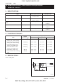
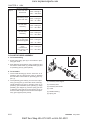
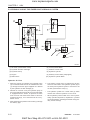
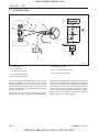
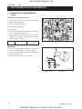
D. OIL PRESSURE SWITCH
The oil pressure switch is installed on the cylinder
block and leads to the oil passage of the lubricating
oil. When the oil pressure falls below the specified
value, the contacts of the oil pressure switch closes to
turn on the warning lamp (1).
569W221A
(A) At lower Oil Pressure
(49 kPa (0.5 kgf/cm2, 7 psi) or less)
(B) At Proper Oil Pressure
(1) Warning Lamp
(6) Rubber washer
(2) Battery
(7) Oil Pressure
(3) Contact Movable
(8) Cylinder Block
(4) Contact Cup
(9) Pressure
(5) Diaphragm
2-12
D569-W02 May-2003
K&T Saw Shop 606-678-9623 or 606-561-4983
www.mymowerparts.com
ENGINE
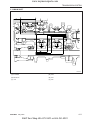
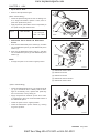
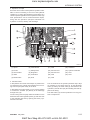
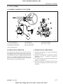
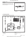
2.3 COOLING SYSTEM
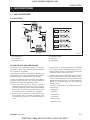
A. FLOW OF COOLING WATER
The cooling system consists of a radiator (5), a centrifugal water pump (7), a cooling fan (6) and a thermostat (2). The water is cooled as it flows through the
radiator core, and the fan behind the radiator pulls the
cooling air through the radiator core. The water pump
receives water from the radiator or from the cylinder
head and forces it into cylinder block. The thermostat
open or closes according to the water temperature.
When the water temperature is high, the thermostat
opens to allow the water to flow from the cylinder block
to the radiator. When the water temperature is low, the
thermostat closes and the flow stays within the block.
The opening temperature of the thermostat is approx.
70 °C (160 °F).
569W222A
(1) Water Return Pipe
(2) Thermostat
(3) Cylinder Head Water Jacket
(4) Cylinder Block Water Jacket
(5) Radiator
(6) Cooling Fan
(7) Water Pump
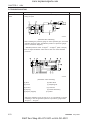
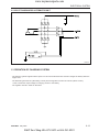
B. WATER PUMP
The water pump is driven with the fan drive pulley, which
is on the water pump shaft and driven by the crankshaft
with a belt. The water pump sucks the cooled water,
forces into the cylinder block and draws out the hot
water to the radiator repeatedly. The mechanical seal
(3) prevents the water from entering the bearing (1).
569W223A
(a) From the Thermostat
(b) To the Cylinder Block
(c) From the Radiator
(1) Bearing
(3) Mechanical Seal
(2) Pump Body
(4) Pump Impeller
D569-W02 May-2003
K&T Saw Shop 606-678-9623 or 606-561-4983
2-13
www.mymowerparts.com
CHAPTER 2
8454
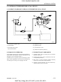
C. THERMOSTAT
The thermostat is wax pellet type, which controls the
flow of the cooling water to the radiator to keep the
proper temperature. The case has a seat (1) and the
pellet has a valve (2). The spindle attached to the case
is inserted into the synthetic rubber in the pellet. The
pellet is charged with wax.
(A) At low temperature (lower than 71 °C (160 °F)). The
valve (2) is seated by the spring (7) and the cooling
water circulates in the engine through the water return
pipe but does not enter the radiator.
(B) At high temperature (higher than 71 °C (160° F)). As
the water temperature rises, the wax in the pellet (3)
turns liquid and expands, repelling the spindle. The
pellet lowers and the valve (2) opens to send the cooling water to the radiator.
569W224A
(1) Seat
(6) Wax (Solid)
(2) Valve
(7) Spring
(3) Pellet
(8) Leak Hole
(4) Spindle
(9) Wax (Liquid)
(5) Synthetic Rubber
D. RADIATOR
The radiator core consists of water carrying tubes (2)
with fins (3) at a right angle to it. The water in the radiator is cooled by the air flowing through between the
tube wall and the fin.
569W225A
(1) Cooling Air
(3) Fin
(2) Tube
E. RADIATOR CAP
The pressure type cap is installed on the radiator, which
prevents the pressure difference between the inside
and the outside of the radiator from deforming the radiator.
(A) At high pressure
Higher than 88 kPa (0.9 kgf/cm2, 13 psi) when the coolant temperature rises and the pressure in the radiator
increase above the specified pressure, the pressure
valve (1) opens to reduce the internal pressure.
(B) At low pressure
When the coolant temperature falls and a vacuum is
formed in the radiator, the vacuum valve (2) opens to
allow coolant stored in the over flow tank to enter the
radiator.
2-14
569W226A
(1) Pressure Valve
(2) Vacuum Valve
D569-W02 May-2003
K&T Saw Shop 606-678-9623 or 606-561-4983
www.mymowerparts.com
ENGINE
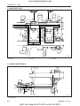
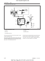
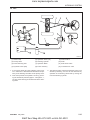
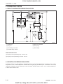
2.4 FUEL SYSTEM
A. FLOW OF FUEL
The fuel is fed from the fuel tank (1) through the fuel
feed pump (7) to the injection pump (3) thru the fuel
filter (2). The injection pump force-feds the fuel through
the injection nozzles (5), which inject the fuel into the
cylinders for combustion. The excessive fuel from the
injection pump to the injection nozzles is collected in
the fuel overflow pipes (6) and returns to the fuel tank.
569W227A
(1) Fuel Tank
(5) Injection Nozzle
(2) Fuel Filter
(6) Fuel Overflow Pipe
(3) Injection Pump
(7) Fuel Feed Pump
(4) Injection Pipe
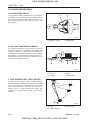
B. FUEL FILTER
The fuel filter removes dirt and water with its fine filter
paper, which collects particles of 90 microns (0.0034
in.) at 20 kPa (0.2 kgf/cm2, 3 psi). The fuel from the fuel
feed pump is filtered by the filter element (6), while
flowing through the filter body (3). The air vent (2) returns the air in the fuel to the fuel tank to prevent the
engine from stopping or running irregularly.
569W228A
(a) To Fuel Tank
(b) From Fuel Feed Pump
(c) To Injection Pump
(1) Cock
(4) Retainer Ring
(2) Air Vent
(5) Pot
(3) Filter Body
(6) Filter Element
D569-W02 May-2003
K&T Saw Shop 606-678-9623 or 606-561-4983
2-15
www.mymowerparts.com
CHAPTER 2
8454
C. FUEL FEED PUMP
The diaphragm (6) is linked to the tappet (3) with a
push rod (2). The tappet is reciprocated by the eccentric cam on the fuel camshaft (7).
(A) Inlet stroke
When the diaphragm is pulled down by the spring,
vacuum in the chamber (5) causes the outlet valve (4)
to close and the atmospheric pressure in the fuel tank
forces the fuel into the chamber, opening the inlet valve
(1).
(B) Discharge stroke
When the diaphragm is pushed up by the cam, the
pressure in the chamber causes the inlet valve to close
and forces out the fuel, opening the outlet valve.
569W229A
(a) From Fuel Tank
(b) To Fuel Filter
(1) Inlet Valve
(5) Chamber
(2) Push Rod
(6) Diaphragm
(3) Tappet
(7) Fuel Camshaft
(4) Outlet Valve
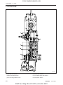
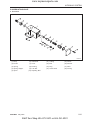
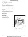
D. FUEL INJECTION PUMP
The injection pump is bosch K type mini injection
pump. It features a compact and light weight design.
569W230A
(a) To Injection Nozzle
(b) From Fuel Filter
2-16
(1) Delivery Valve Holder
(5) Plunger
(2) Delivery Valve Spring
(6) Control Rack
(3) Delivery Valve
(7) Plunger Spring
(4) Cylinder
(8) Tappet
D569-W02 May-2003
K&T Saw Shop 606-678-9623 or 606-561-4983
www.mymowerparts.com
ENGINE
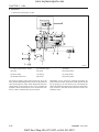
a . Pump Element
The pump element (1) consists of a plunger (3) and
cylinder (2), their sliding surfaces are precision machined to maintain fuel tightness. The plunger (3) fits
in the control sleeve (5) at the driving surface (7). The
sleeve is engaged with the control rack, which rotate
the plunger in the cylinder to control the amount of fuel
delivery.
569W231A
(1) Pump Element
(5) Control Sleeve
(2) Cylinder
(6) Control Groove
(3) Plunger
(7) Driving Surface
(4) Feed Hole
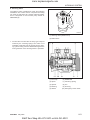
b. Operation of Pump Element
(A) Before delivery
As the taper lowers, the plunger (2) lowers and fuel is
drawn into the delivery chamber (1) through the feed
hole (4) from the fuel chamber (5).
(B) Beginning of delivery
When the plunger is pushed up by the cam and the
head of the plunger closes the feed hole (4), the pressure in the delivery chamber (1) rises to push the delivery valve (3) open.
(C) Delivery
While the plunger (2) is rising, delivery of fuel continues.
(D) End of delivery
When the plunger rises further and the control groove
(6) on its periphery meets the feed hole, the fuel returns to the fuel chamber (5) from the delivery chamber
(1) through the control groove (6) and the feed hole (4).
569W232A
(1) Delivery Chamber
(4) Feed Hole
(2) Plunger
(5) Fuel Chamber
(3) Delivery Valve
(6) Control Groove
D569-W02 May-2003
K&T Saw Shop 606-678-9623 or 606-561-4983
2-17
www.mymowerparts.com
CHAPTER 2
8454
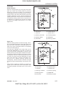
c. Amount of Fuel Delivery
(A) No fuel delivery
At the engine stop position of the control rack (3), the
lengthwise slot (1) on the plunger (2) aligns with the
feed hole (5). The delivery chamber (4) is led to the
feed hole during the entire stroke of the plunger. The
pressure in the delivery chamber does not build up
and no fuel is forced to the injection nozzle.
(B) Fuel delivery
The plunger is rotated by the control rack and the feed
hole is not aligned with the lengthwise slot. When the
plunger is pushed up, the feed hole is closed by the
plunger. The pressure in the delivery chamber builds
up and forces the fuel to the injection nozzle until the
control groove (6) meets the feed hole. The amount of
the fuel to be forced into the nozzle corresponds to
distance A.
569W233A
(1) Slot
(4) Delivery Chamber
(2) Plunger
(5) Feed Hole
(3) Control Rack
(6) Control Groove
d. Delivery Valve
The delivery valve prevents the fuel in the injection pipe
from flowing back into the delivery chamber and the
fuel in the injection nozzle from dribbling after injection.
569W234A
2-18
(1) Valve Spring
(4) Fuel Chamber
(2) Valve
(5) Valve Face
(3) Valve Seal
(6) Relief Plunger
D569-W02 May-2003
K&T Saw Shop 606-678-9623 or 606-561-4983
www.mymowerparts.com
ENGINE
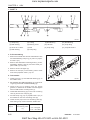
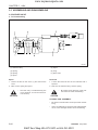
E. FUEL INJECTION NOZZLE
The nozzle is a throttle-type. It features low fuel consumption and works well with DAEDONG combustion
chamber. The nozzle valve opening pressure is about
13.7 to 14.7 MPa (140 to 150 kgf/cm2, 1,991 to 2,134
psi), the pressure overcomes the counterforce of nozzle
valve spring, and push the valve up instantly, the fuel is
then injected in a proper quantity into the swirling air in
the combustion chamber for combustion. Addition or
reduction of adjusting shims can adjust the opening
pressure. A washer of 0.1 mm corresponds to 980 kPa
(10 kgf/cm 2, 142 psi) change in opening pressure. The
heat seal is employed to improve the durability and
reliability of the nozzle.
569W235A
(1) Nozzle Holder Ass’y
(6) Nozzle Body
(2) Adjusting Washer
(7) Needle Valve
(3) Nozzle Spring
(8) Heat Seal
(4) Push Rod
(9) Packing
(5) Retaining Nut
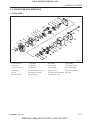
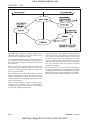
F. GOVERNOR AND IDLE COMPENSATING
a . Disassembled View
The governor serves to keep engine speed constant by
automatically adjusting the amount of fuel supplied to
the engine according to changes in the load. The engine employs an all-speed governor which is controlled
by the centrifugal force of the steel ball (13) weights,
produced by rotation of the fuel camshaft (9), and tension of the governor spring 1 (2) and 2 (3) are balanced.
569W236A
(1) Start Spring
(8) Governor Lever
(2) Governor Spring 1
(9) Fuel Camshaft
(3) Governor Spring 2
(10) Governor Ball Case
(4) Fork Lever 1
(11) Steel Ball
(5) Fork Lever 2
(12) Governor Sleeve
(6) Fork Lever Shaft
(13) Steel Ball
(7) Fork Lever Holder
D569-W02 May-2003
K&T Saw Shop 606-678-9623 or 606-561-4983
2-19
www.mymowerparts.com
CHAPTER 2
8454
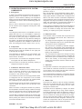
b. Operation of Governor
a) At start
The steel balls (13) have no centrifugal force. As the
fork lever 1 (4) is pulled by the start spring (1), the
control rack (14) moves to the maximum injection position. At start, the sufficient injection of the fuel enables
easy starting.
569W237A
(1) Start Spring
(13) Steel Ball
(4) Fork Lever 1
(14) Control Rack
b) At idling
At the idling position of the speed control lever (15), the
governor spring 1 (2) is free and the governor spring 2
(3) only acts slightly. The governor sleeve (12) is
pushed leftward by a centrifugal force of steel ball (13).
Therefore, the fork lever 1 (4) and control rack (14) are
moved to the rear by the governor sleeve (12) and then
the idling adjusting spring (16) is compressed by the
control rack (14). As a result, the control rack (14) is
kept at a position where the centrifugal force of steel
ball (13) and forces of the start spring (1), governor
spring 2 (3) and idling limit spring are balanced, providing stable idling.
IMPORTANT:
•
The idling speed has been factory-set. The idling
adjusting screw (20) and spring (16) should not be
disassembled and readjusted.
569W238A
(1) Start Spring
(13) Steel Ball
(2) Governor Spring 1
(14) Control Rack
(3) Governor Spring 2
(15) Speed Control Lever
(4) Fork Lever 1
(16) Idle Adjusting Spring
(12) Governor Sleeve
2-20
(20) Idle Adjusting Screw
D569-W02 May-2003
K&T Saw Shop 606-678-9623 or 606-561-4983
www.mymowerparts.com
ENGINE
c) At High Speed Running with a Load
When a load is applied to an engine running at high
speed, the engine speed drops and the centrifugal force
of steel ball (13) becomes less, the fork lever 2 (5) is
pulled forward by the governor spring 1 (2) and 2 (3),
this increases the amount of fuel injected.
The fork lever 2 (5) becomes ineffective in increasing
the fuel injection when it is stopped by the adjusting
bolt (17). After that, when the force of torque spring (18)
becomes greater than the centrifugal force of the steel
balls, fork lever 1 (4) moves forward to increase fuel
injection, causing the engine to run continuously at a
high torque.
569W239A
(2) Governor Spring 1
(13) Steel Ball
(3) Governor Spring 2
(17) Adjusting Bolt
(4) Fork Lever 1
(18) Torque Spring
(5) Fork Lever 2
d) To stop engine
When the stop lever (19) is moved to the STOP position,
fork lever 1 (4) is moved rearward and the control rack
(14) is moved to the non-injection position, causing
the engine to stop.
569W240A
(4) Fork Lever 1
(19) Stop Lever
(14) Control Rack
D569-W02 May-2003
K&T Saw Shop 606-678-9623 or 606-561-4983
2-21
www.mymowerparts.com
CHAPTER 2
8454
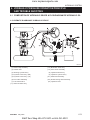
2.5 INTAKE AND EXHAUST SYSTEM
A. FLOW OF INTAKE AIR AND EXHAUST GAS
(a) Intake Air
(b) Exhaust Gas
(1) Intake Manifold
(2) Air Cleaner
(3) Cylinder Head
(4) Muffler
(5) Exhaust Manifold
569W241A
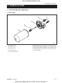
B. AIR CLEANER
The air cleaner is dry-cyclone type and easy to maintain.
The air from the inlet port (2) circulates along the fin (3)
and around the air cleaner element (4) and the heavier
dust is carried to the evacuator (6), to the dust exhaust
port. The fine dust in the air is filtered with the air cleaner
element (4), and the filtered air flows to the outlet port
(1).
569W242A
(a) Inlet Air
(b) To Intake Manifold
(c) Heavier Dust
(1) Outlet Port
(4) Air Cleaner Element
(2) Inlet Port
(5) Body
(3) Fin
(6) Evacuator
C. MUFFLER
The exhaust noises are absorbed, while the gases are
passed through a series of holes on the inner tube
and glass wool of the muffler.
569W243A
2-22
D569-W02 May-2003
K&T Saw Shop 606-678-9623 or 606-561-4983
www.mymowerparts.com
ENGINE
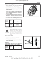
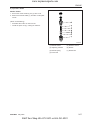
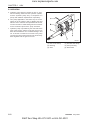
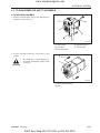
D. TURBOCHARGER (8454)
The mechanism of turbocharger is the use of exhaust
gas energy which rotates turbine and the power is
transmitted to air compressor by a shaft. So it is possible to supply more fuel to a cylinders and this will
increase the power.
It is recommended not to accelerate suddenly just about
starting or stopping the engine suddenly after driving.
Since the turbocharger runs above 100,000 rpm it is
necessary to allow the engine to idle for 1 or 2 minutes
before stopping, this protect the bearings of the turbocharger.
To keep a capacity of turbocharger you should check
the engine oil and air cleaner periodically. Turbocharger
is composed of precision parts. Do not disassemble
or repair without permission.
Turbocharger actuator pressure is 460 mmHg.
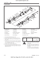
The structure of turbocharger is as above.
569W244A
(A) Compressor Ambient Air Inlet
(B) Compressor Air Discharge
(C) Turbine Exhaust Gas Inlet
(C) Turbine Exhaust Gas Inlet
(1) Turbine Wheel
(2) Compressor Wheel
569W245A
(A) Fresh Air Inlet
(B) Exhaust Outlet
(C) Exhaust Inlet
(1) Compressed Air Outlet
(2) Compressor Seal
(3) Oil Inlet
(4) Journal Bearing
(5) Turbine Seal
(6) Turbine Wheel
(7) Compressor Wheel
(8) Thrust Bearing
D569-W02 May-2003
(9) Oil Drain
K&T Saw Shop 606-678-9623 or 606-561-4983
2-23
www.mymowerparts.com
CHAPTER 2
8454
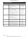
3. DISASSEMBLING AND SERVICING
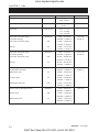
3.1 TROUBLESHOOTING
Symptom
Engine Does Not Start
(Starter Does Not Run)
Engine Revolution is Not Smooth
2-24
Probable Cause
Solution
• Not fuel
Replenish fuel
• Air in the fuel system
• Water in the fuel system
Vent air
Change fuel and repair or flush
fuel system
• Fuel pipe clogged
Clean
• Fuel filter clogged
• Excessively high viscosity of fuel
or engine oil at low temperature
Clean or replace
Use the specified fuel or engine
oil
• Fuel with low cetane number
Use the specified fuel
• Fuel leak due to loose injection
pipe retaining nut
• Incorrect injection timing
Tighten nut
• Fuel camshaft worn
Replace
• Injection nozzle clogged
• Injection pump malfunctioning
Clean or replace
Repair or replace
• Fuel transfer pump
malfunctioning
Repair or replace
• Seizure of transfer pump
malfunctioning piston, cylinder
bore or bearing
• Compression leak from cylinder
Repair or replace
• Improper valve seating, valve
spring broken, valve seized
Repair or replace
• Improper valve timing
• Piston ring and bore worn
Correct or replace timing gear
Repair or replace
• Excessive valve clearance
Adjust
• Battery discharged
• Starter malfunction
Charge
Repair or replace
• Starter switch malfunction
Repair or replace
• Wiring disconnected
• Fuel filter clogged or dirty
Connect
Clean or replace
• Air cleaner clogged
Clean or replace
• Fuel leak due to loose injection
pipe retaining nut
• Injection pump malfunctioning
Tighten nut
• Incorrect nozzle opening
pressure
Adjust
• Nozzle stuck or clogged
• Fuel over flow pipe clogged
Repair or replace
Clean
• Governor malfunctioning
Repair
Adjust
Replace head gasket, tighten
cylinder head screws, glow plug
and nozzle holder
Repair or replace
D569-W02 May-2003
K&T Saw Shop 606-678-9623 or 606-561-4983
www.mymowerparts.com
ENGINE
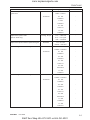
Symptom
Either White or Blue Exhaust
Gas is Observed
Either Black or Dark Gray
Exhaust Gas is Observed
Insufficient Output
Excessive Lubrication Oil
Consumption
Fuel Mixed into
Lubricating Oil
Probable Cause
Solution
• Excessive engine oil
• Piston ring and bore worn or
piston ring stuck
Reduce to the specified level
Repair or replace
• Incorrect injection timing
Adjust
• Insufficient compression
• Over heated
Adjust top clearance
Lessen the load
• Low grade fuel used
Use the specified fuel
• Fuel filter clogged
• Air cleaner clogged
Clean or replace
Clean or replace
• Incorrect injection timing
Adjust
• Engine’s moving parts seem to
be seizing
• Uneven fuel injection
Repair or replace
• Insufficient nozzle injection
Repair or replace the nozzle
• Compression leak
Replace head gasket, tighten
cylinder head screws and nuts,
glow plug and nozzle holder
Shift ring gap direction
• Piston ring’s gap facing the
same direction
Repair or replace the injection
pump
• Oil ring worn or stuck
Replace
• Piston ring groove worn
• Valve stem and guide worn
Replace the piston
Replace
• Crankshaft bearings, and crank
pin bearings worn
• Injection pump plunger worn
Replace
Replace pump element or pump
• Fuel transfer pump broken
Replace
Water Mixed Into Lubricating oil
• Head gasket defective
• Cylinder block or cylinder head
cracked
Replace
Replace
Low Oil Pressure
• Engine oil insufficient
Replenish
• Oil strainer closed
• Oil filter cartridge clogged
Clean
Replace
• Relief valve stuck with dirt
Clean
• Relief valve spring weak or
broken
• Excessive oil clearance of
crankshaft bearings
Replace
• Excessive oil clearance of crank
pin bearings
Replace
• Excessive oil clearance of rocker
arm bushings
• Oil passage closed
Replace
• Improper type of oil
Use the specified type of oil
• Oil pump defective
Repair or replace
Replace
Clean
D569-W02 May-2003
K&T Saw Shop 606-678-9623 or 606-561-4983
2-25
www.mymowerparts.com
CHAPTER 2
8454
Symptom
Probable Cause
• Improper type of oil
High Oil Pressure
• Relief valve defective
Engine Overheating
Replenish
• Cooling water insufficient
Replenish
• Radiator net and radiator fin
clogged with dirt
• Inside of radiator corroded
Clean
• Radiator cap defective
• Water pipe damaged
• Thermostat defective
• Water pump defective
• Mechanical seal defective
• Overload running
• Head gasket defective
• Incorrect injection timing
• Unsuitable fuel used
2-26
Use the specified type of oil
Replace
• Engine oil insufficient
• Fan belt broken or tensioned
improperly
• Cooling water flow route
corroded
Battery Quickly Discharge
Solution
Replace or adjust
Clean or replace
Clean or replace
Replace
Replace
Replace
Replace
Replace
Lesson the load
Replace
Adjust
Use the specified fuel
• Battery electrolyte insufficient
Replenish distilled water and
charge
• Fan belt slips
• Wiring disconnected
Adjust belt tension or replace
Connect
• Regulator defective
• Alternator defective
Replace
Replace
• Battery defective
Replace
D569-W02 May-2003
K&T Saw Shop 606-678-9623 or 606-561-4983
www.mymowerparts.com
ENGINE
3.2 SERVICING SPECIFICATIONS
A. ENGINE BODY
a . Cylinder Head
Item
Factory Specification
Allowable Limit
0.05 mm / 100 mm
Cylinder Head Surface Flatness
0.002 in. / 3.94 in.
0.75 ~ 0.9 mm
Top Clearance
-
0.0295 ~ 0.0354 in.
Cylinder Head Gasket Thickness
1.3 ~ 1.5 mm
Free
0.0512 ~ 0.0591 in.
-
1.15 ~ 1.25 mm
Tightened
0.0453 ~ 0.0492 in.
Compression Pressure
(When cranking with starting motor)
3.24 ~ 3.73 MPa
2.55 MPa
33 ~ 38 kgf/cm2
26 kgf/cm2
469 ~ 540 psi
370 psi
* Variance of compression pressure among cylinders should be 10% or less.
b. Valves
Factory Specification
Item
Valve Clearance (Cold)
Valve Seat Angle
Valve Face Angle
Allowable Limit
4A220
4A200T
IN.
0.25 mm 0.0098 in.
015 mm 0.0059 in.
EX.
0.30 mm 0.0118 in.
0.15 mm 0.0059 in.
IN.
1.047 rad. 60°
1.047 rad. 60°
EX.
0.785 rad. 45°
0.785 rad. 45°
IN.
1.047 rad. 60°
1.047 rad. 60°
EX.
0.785 rad. 45°
0.785 rad. 45°
0.2 ~ 0.5 mm
0.2 ~ 0.5 mm
0.8 mm
0.0079 ~ 0.0197 in.
0.0079 ~ 0.0197 in.
0.0315 in.
0.040 ~ 0.070 mm
0.040 ~ 0.070 mm
0.10 mm
0.00157 ~ 0.00276 in.
0.00157 ~ 0.00276 in.
0.0039 in.
7.960 ~ 7.975 mm
7.960 ~ 7.975 mm
0.31339 ~ 0.31398 in.
0.31339 ~ 0.31398 in.
Valve Recessing
Clearance Between Valve Stem and Valve
Guide
Valve Stem O.D
8.015 ~ 8.030 mm
8.015 ~ 8.030 mm
0.31555 ~ 0.31614 in.
0.31555 ~ 0.31614 in.
Valve Stem I.D
-
-
c. Valve Timing
Item
Inlet Valve
Exhaust Valve
Factory Specification
Open
0.140rad 8° before T.D.C
Close
0.611rad 35° after B.D.C
Open
0.785rad 45° before B.D.C
Close
0.140rad 8° after T.D.C
Allowable Limit
D569-W02 May-2003
K&T Saw Shop 606-678-9623 or 606-561-4983
-
-
2-27
www.mymowerparts.com
CHAPTER 2
8454
d. Cylinder Bore
Item
Cylinder bore inner
diameter
Factory Specification
Allowable Limit
4A220
87.000 ~ 87.022 mm
3.4252 ~ 3.4261 in.
0.15 mm
4A200T
83.000 ~ 83.022 mm
0.0059 in.
3.2677 ~ 3.2690 in.
e . Valve Spring
Item
Free length
Assembling load / assembling length
Squareness
Factory Specification
Allowable Limit
41.7 ~ 42.2 mm
41.2 mm
1.6417 ~ 1.6614 in.
1.6220 in.
12.0 kgf / 35.15 mm
10.2 kgf / 35.15 mm
26.46 lbs / 1.3839 in.
22.49 lbs / 1.3839 in.
-
1.0 mm
0.0394 in.
f. Rocker Arm
Item
Factory Specification
Rocker arm shaft O.D
Allowable Limit
18.955 ~ 18.980 mm
-
0.74600 ~ 0.74724 in.
Rocker arm bushing I.D
19.0 ~ 19.035 mm
-
0.74803 ~ 0.74941 in.
g. Tappet
Item
Clearance between tappet and guide
Tappet O.D
Factory Specification
Allowable Limit
0.020 ~ 0.062 mm
0.07 mm
0.00079 ~ 0.00244 in.
0.0028 in.
23.959 ~ 23.980 mm
-
0.94327 ~ 0.94410 in.
24.000 ~ 24.021 mm
Tappet guide I.D
-
0.94488 ~ 0.94571 in.
h. Camshaft
Item
Camshaft alignment
Cam height
IN. (4A200T, 4A220)
EX. (4A200T, 4A220)
Clearance between camshaft
Camshaft journal O.D
Camshaft counter bore I.D
Factory Specification
Allowable Limit
0.01 mm
0.05 mm
0.0004 in.
0.0020 in.
33.90, 33.59 mm
33.85, 33.54 mm
1.3346, 1.3224 in.
1.3327, 1.3205 in.
33.70, 33.69 mm
33.65, 33.64 mm
1.3268, 1.3264 in.
1.3248, 1.3244 in.
0.050 ~ 0.091 mm
0.15 mm
0.00197 ~ 0.00358 in.
0.0059 in.
39.934 ~ 39.950 mm
39.88 mm
1.57221 ~ 1.57284 in.
1.5701 in.
40.000 ~ 40.025 mm
-
1.57480 ~ 1.57579 in.
2-28
D569-W02 May-2003
K&T Saw Shop 606-678-9623 or 606-561-4983
www.mymowerparts.com
ENGINE
I. Timing Gear
Item
Timing gear backlash
Idle gear side clearance
Clearance between
Factory Specification
Allowable Limit
0.04 ~ 0.11 mm
0.15 mm
0.0016 ~ 0.0043 in.
0.0059 in.
0.20 ~ 0.51 mm
0.9 mm
0.0079 ~ 0.0201 in.
0.035 in.
Idle gear shaft and idle
gear bushing
0.025 ~ 0.066 mm
0.1 mm
0.00098 ~ 0.00260 in.
0.0039 in.
Idle gear shaft O.D
37.959 ~ 37.975 mm
-
1.49445 ~ 1.49508 in.
Idle gear bushing I.D
38.000 ~ 38.025 mm
-
1.49606 ~ 1.49705 in.
j. Piston Ring
Item
Piston pin-bore I.D
Clearance between
Oil ring and ring groove
Oil ring groove width
Factory Specification
Allowable Limit
25.000 ~ 25.006 mm
25.03 mm
0.98425 ~ 0.98448 in.
0.9854 in.
0.020 ~ 0.060 mm
0.15 mm
0.00079 ~ 0.00236 in.
0.0059 in.
3.010 ~ 3.030 mm
-
0.11850 ~ 0.11929 in.
Oil ring width
2.97 ~ 2.99 mm
-
0.11693 ~ 0.11772 in.
Clearance between
2nd ring and ring groove
2nd ring groove width
0.04 ~ 0.08 mm
0.15 mm
0.00157 ~ 0.00315 in.
0.0059 in.
2.03 ~ 2.05 mm
-
0.07992 ~ 0.08070 in.
2nd ring width
1.97 ~ 1.99 mm
-
0.07756 ~ 0.07834 in.
Top ring, oil ring end gap
2nd ring end gap
0.25 ~ 0.40 mm
1.25 mm
0.0098 ~ 0.01570 in.
0.0492 in.
0.55 ~ 0.70 mm
1.25 mm
0.0217 ~ 0.0276 in.
0.0492 in.
Factory Specification
Allowable Limit
k. Connecting Rod
Item
Connecting rod misalignment
-
0.05 mm
0.0020 in.
Clearance between
Piston and small end
bushing
0.014 ~ 0.038 mm
0.15 mm
0.00055 ~ 0.00150 in.
0.0059 in.
Piston pin O.D
25.002 ~ 25.011 mm
0.98433 ~ 0.98469 in.
Small end bushing I.D
-
25.025 ~ 25.040 mm
0.98524 ~ 0.98583 in.
D569-W02 May-2003
K&T Saw Shop 606-678-9623 or 606-561-4983
-
2-29
www.mymowerparts.com
CHAPTER 2
8454
l. Crankshaft
Item
Factory Specification
Crankshaft Misalignment
Clearance between
Allowable Limit
0.08 mm
-
0.0031 in.
Crankshaft and crankshaft bearing 1
0.040 ~ 0.118 mm
0.20 mm
0.00157 ~ 0.00465 in.
0.0079 in.
Crankshaft O.D
51.921 ~ 51.940 mm
-
2.04414 ~ 2.04489 in.
Crankshaft bearing 1 I.D
51.980 ~ 52.039 mm
-
2.04646 ~ 2.04878 in.
Clearance between
Crankshaft and crankshaft bearing 2
Crankshaft O.D
0.040 ~ 0.104 mm
0.20 mm
0.00157 ~ 0.00409 in.
0.0079 in.
51.921 ~ 51.940 mm
-
2.04414 ~ 2.04488 in.
Crankshaft bearing 1 I.D
51.980 ~ 52.025 mm
-
2.04646 ~ 2.04823 in.
Clearance between
Crank pin and crank pin
bearing
0.025 ~ 0.087 mm
0.20 mm
0.00098 ~ 0.00343 in.
0.0079 in.
Crank pin O.D
46.959 ~ 46.975 mm
-
1.84876 ~ 1.84947 in.
Crank pin bearing I.D
47.000 ~ 47.046 mm
-
1.85040 ~ 1.85221 in.
Crankshaft side clearance
0.15 ~ 0.31 mm
0.5 mm
0.0059 ~ 0.0122 in.
0.020 in.
Factory Specification
Allowable Limit
B. LUBRICATING SYSTEM
a . Oil Pump
Item
At idle speed
Engine oil pressure
more than 49.0 kPa
0.5 kgf/cm2
(oil temp. 85 ~ 95 °C,
185 ~ 203 °F)
At rated speed
Clearance between inner rotor and outer rotor
Radial clearance between outer rotor and pump
End clearance between inner rotor and cover
245 kPa
245 ~ 441 kPa
2.5 ~ 4.5 kgf/cm
2-30
-
7.11 psi
2
2.5 kgf/cm2
35.6 ~ 64.0 psi
35.6 psi
0.10 ~ 0.16 mm
0.2 mm
0.0039 ~ 0.0063 in.
0.0079 in.
0.11 ~ 0.19 mm
0.25 mm
0.0043 ~ 0.0078 in.
0.0098 in.
0.105 ~ 0.150 mm
0.2 mm
0.00413 ~ 0.00591 in.
0.00787 in.
D569-W02 May-2003
K&T Saw Shop 606-678-9623 or 606-561-4983
www.mymowerparts.com
ENGINE
C. COOLING SYSTEM
a . Thermostat
Valve opening temperature at beginning
69.5 ~ 72.5 °C (157.1 ~ 162.5 °F)
Opened completely (height 8 mm 0.315 in.)
85 °C (185 °F)
b. Radiator
Radiator tightness
No leak at 137 kPa, 1.4 kgf/cm2, 20 psi
10 seconds or more for pressure
falling from 88 ~ 59 kPa
from 0.9 ~ 0.6 kgf/cm 2
Radiator cap tightness
from 13 ~ 9 psi
Fan belt tension
7 ~ 9 mm
[deflection at 98 N (10 kgf, 22 lbs) of force]
0.28 ~ 0.35 in.
D. FUEL SYSTEM
a . Inject Pump
Injection timing (BTDC)
4A220
18°
4A200T
12°
b. Injection Nozzle
Fuel injection pressure
13.73 ~ 14.715 MPa
140 ~ 150 kgf/cm2
1,991 ~ 2,134 psi
Fuel tightness of nozzle valve seat
No fuel leak for 5 sec.
at pressure
12.74 MPa
130 kgf/cm2
1,849 psi
NOTE:
•
Injection Sequence Four Cylinders: 1 → 3 → 4 → 2
(The cylinder number is given in order from the
gear case end.)
D569-W02 May-2003
K&T Saw Shop 606-678-9623 or 606-561-4983
2-31
www.mymowerparts.com
CHAPTER 2
8454
E. TIGHTENING TORQUES
Size x Pitch
N•m
kgf•m
lbf·ft
Cylinder head screws
M11 x 1.25
103.0 ~ 107.9
10.5 ~ 11.0
75.9 ~ 79.6
Head cover nuts
M10 x 1.25
8.8 ~ 10.8
0.9 ~ 1.1
6.5 ~ 8.0
* Bearing case screw 1
M9 x 1.25
46.1 ~ 51.0
4.7 ~ 5.2
34.0 ~ 37.6
* Bearing case screw 2
M10 x 1.25
68.6 ~ 73.6
7.0 ~ 7.5
50.6 ~ 54.2
* Flywheel screw
M12 x 1.25
98.1 ~ 107.9
10.0 ~ 11.0
72.3 ~ 79.6
* Connecting rod screws
M8 x 1.0
46.1 ~ 51.0
4.5 ~ 5.0
34.0 ~ 37.6
Rocker arm bracket studs
M10 x 1.25
48.1 ~ 55.9
4.9 ~ 5.7
35.4 ~ 41.2
Drain plug
M12 x 1.25
32.4 ~ 37.3
3.3 ~ 3.8
23.9 ~ 37.3
Glow plugs
M10 x 1.25
19.6 ~ 24.5
2.0 ~ 2.5
14.5 ~ 18.1
PT1/8
14.7 ~ 19.6
1.5 ~ 2.0
10.8 ~ 14.5
Item
Oil switch
Nozzle locating screws
M20 x 1.5
49.1 ~ 68.7
5.0 ~ 7.0
36.2 ~ 50.6
Injection pipe nuts
M12 x 1.5
24.5 ~ 34.3
2.5 ~ 3.5
18.1 ~ 25.3
NOTE:
•
For *marked screw, bolts and nuts on the table,
apply engine oil to their threads and seats before
tightening.
•
The letter “M” in Size x Pitch means that the screw,
bolt or nut dimension stands for metric. The size is
the nominal outside diameter in mm of the threads.
The pitch is the nominal distance in mm between
two threads.
2-32
D569-W02 May-2003
K&T Saw Shop 606-678-9623 or 606-561-4983
ENGINE
3.3 CHECKING, DISASSEMBLING AND SERVICING
A. ENGINE DISASSEMBLED VIEW
www.mymowerparts.com
K&T Saw Shop 606-678-9623 or 606-561-4983
615WA18A
(1)
(2)
(3)
(4)
(5)
(6)
Cylinder Block
Oil Pressure Switch
Oil Pump
Oil Pan
Oil Strainer
Oil Gauge
D569-W02 May-2003
(7)
(8)
(9)
(10)
(11)
Cylinder Head
Head Bolt
Gear case
Oil Filter
Main bearing Case
Cover
(12)
(13)
(14)
(15)
(16)
(17)
Bearing Case Bolt 1
Main Bearing Case
Bearing Case Bolt 2
Rocker Arm
Inlet, Exhaust Valve
Cylinder Hear Cover
(18)
(19)
(20)
(21)
(22)
(23)
Push Rod
Tappet
Camshaft
Camshaft Gear
Idle Gear
Piston
(24)
(25)
(26)
(27)
(28)
(29)
Connecting Rod
Crankshaft
Flywheel
Flywheel Housing
Starter
Injection Pipe
(30)
(31)
(32)
(33)
(34)
(35)
Glow Plug
Nozzle
Fuel Injection Pump
Fuel Feed Pump
Fuel Camshaft
Fuel Camshaft Gear
(36)
(37)
(38)
(39)
(40)
(41)
Engine Stop Solenoid
Speed Control Plate
Fork Lever (Governor)
Impeller
Thermostat
Alternator
(42)
(43)
(44)
(45)
(46)
(47)
Fan Drive Pulley
Cooling Fan
Radiator
Reserve Tank Ass’y
Inlet Manifold
Muffler
(48)
(49)
(50)
(51)
Exhaust Manifold
Air Cleaner
Turbo Charger
Air Conditioner
Compressor
2-33
www.mymowerparts.com
K&T Saw Shop 606-678-9623 or 606-561-4983
www.mymowerparts.com
ENGINE
B. EXTERNAL COMPONENTS
a . Checking and Adjusting
1) Fan belt
Measure the deflection, depressing the belt halfway
between the fan drive pulley and the alternator pulley at
98 N (10 kgf, 22 lbs) of force.
If the deflection is not between the factory specifications,
loosen the bolts and nuts, and relocate the alternator
to adjust.
If the belt is damaged or worn (see figure), replace the
belt.
Belt tension
(deflection)
Factory spec
7 ~ 9 mm
569W249A
0.28 ~ 0.35 in.
b. Disassembly and Assembly
1) Engine body
Drain the oil and the water, if disassemble the engine
body.
1. Remove the muffler and exhaust manifold (7).
2. Remove the starter (9) and the oil pressure switch
(8).
3. Pull out the oil gauge (6).
4. Remove the alternator (5) and the fan belt (1).
5. Remove the hour meter unit (2).
6. Loosen the oil filter (3) with a filter wrench and remove it and the oil filter flange (4).
*
This figure does not show Hour meter Unit (2) covered with the cooling fan.
(When reassembling)
Apply liquid gasket (three bond 1,215 or equivalent) on
the thread of the oil pressure switch (8).
569W250A
(1) Fan Belt
(6) Oil Gauge
(2) Hour Meter Unit
(7) Exhaust Manifold
(3) Oil Filter
Switch
(8) Oil Pressure
(4) Oil Filter Flange
(9) Starter
(5) Alternator
Apply liquid gasket to the both sides of the hour meter
gasket.
Apply oil to the O-ring and tighten the oil filter not with
wrench but by hand.
Adjust the fan belt tension (See fan belt).
Tightening
torque
Oil pressure
switch
14.7 ~ 19.6 N·m
1.5 ~ 2.0 kgf·m
10.8 ~ 14.4 lbf·ft
D569-W02 May-2003
K&T Saw Shop 606-678-9623 or 606-561-4983
2-35
www.mymowerparts.com
CHAPTER 2
8454
2) Solenoid
1. Disconnect the stop lever 1 (5) from the engine stop
lever (2).
2. Remove the screw (3) and (4).
3. Remove the solenoid (7) with its support.
(When reassembling)
•
Loosen the solenoid mounting screws.
•
Install the support and complete the linkage between the solenoid (7) and the engine stop lever
(2).
•
Pushing the solenoid (7) plunger to the bottom, pull
the stop lever 2 (6) until the engine stop lever (2) is
turned to the end, then tighten the screws.
569W251A
(1) Screw
(5) Stop Lever 1
(2) Engine Stop Lever
(6) Stop Lever 2
(3) Screw
(7) Solenoid
(4) Screw
3) Intake manifold and fuel pipes
1. Disconnect the fuel pipe (3).
2. Loosen the injection pipe fitting with two wrenches
and remove the injection pipes (2).
3. Remove the intake manifold (1) and the fuel feed
pump (4).
IMPORTANT:
•
Tighten or loosen injection pipe fittings using the
one-hand two-wrench squeeze method.
•
Cap the nozzle hole to prevent entrance of foreign
materials.
Tightening
torque
2-36
Injection pipe
nut 19 mm
(0.75 in.)
cross flats
24.5 ~ 34.3 N·m
2.5 ~ 3.5 kgf·m
18.0 ~ 25.3 lbf·ft
569W252A
(1) Intake Manifold
(3) Fuel Pipe
(2) Injection Pipe
(4) Fuel Feed Pump
D569-W03 May-2003
K&T Saw Shop 606-678-9623 or 606-561-4983
www.mymowerparts.com
ENGINE
C. ENGINE BODY
a . Checking and Adjusting
1) Compression pressure
1. Run the engine until warmed up.
2. Stop the engine and remove the air cleaner, the
muffler and all nozzle holders.
3. Connect a compression tester to the nozzle holder
hole.
4. Pull the stop lever to cut the fuel and run the engine
with the starter at 250 ~ 350 rpm for 5 ~ 10 seconds.
5. Measure the maximum pressure while running, several times.
569W253A
6. If the pressure does not reach the allowable limit,
apply a small amount of oil to the cylinder wall
through the nozzle holder hole and check the pressure again.
7. If the pressure raises after oil is apply, check the
cylinder wall and piston ring.
8. If the pressure is still low, check the top clearance,
valve clearance and cylinder head.
Compression
pressure
Factory spec.
3.24 ~ 3.73 MPa
33 ~ 38 kgf/cm2
469 ~ 540 psi
Allowable limit
2.55 MPa
26 kgf/cm 2
370 psi
Difference
between two
cylinders
Allowable limit
10 %
NOTE:
•
Check the compression pressure with the specified
valve clearance for proper air in taking.
D569-W02 May-2003
K&T Saw Shop 606-678-9623 or 606-561-4983
2-37
www.mymowerparts.com
CHAPTER 2
8454
2) Valve clearance
1. Remove the cylinder head cover and the timing window cover on the flywheel housing and all glow
plugs.
2. Turn the flywheel and align the 1 TC or 1.4 TC mark
mark with the timing mark of window on the flywheel
housing to position the 1st cylinder valves at the top
head center during compression.
3. Measure the clearance at the valves marked with
in the table below with a feeler gauge.
4. If the clearance is not within the factory
specifications, turn the adjusting screw to adjust.
5. Turn the flywheel just one turn to position the 1st
cylinder valves at the top head center during overlap.
569W254A
6. Measure the clearance at the valves marked with
in the table below with a feeler gauge.
7. If the clearance is not within the factory
specifications, adjust it.
Valve
Factory
clearance spec.
4A220
In. : 0.25 mm 0.0098 in.
Ex. : 0.30 mm 0.0118 in.
4A200T
In. : 0.15 mm 0.0059 in.
Ex. : 0.15 mm 0.0059 in.
Cylinder NO.
Valve
1
2
3
4
IN. EX.
IN. EX.
IN. EX.
IN. EX.
569W255B
Checking
b. Disassembling and Assembling
1) Cylinder head cover, glow plugs and fuel
overflow pipes.
1. Remove the injection pipes and over flow pipe.
2. Remove the glow plugs.
3. Remove the injection nozzles and gaskets, heat
seals.
4. Remove the cylinder head cover.
(When reassembling)
•
Check that the cylinder head cover gasket is not
defective.
•
Tighten the cylinder head cover cap nuts in several
steps.
569W256A
(1) Injection Nozzle
(3) Heat Seal
(2) Gasket
2-38
D569-W03 May-2003
K&T Saw Shop 606-678-9623 or 606-561-4983
www.mymowerparts.com
ENGINE
2) Heat seal removal procedure
1. Drive screw driver lightly into the heat seal hole.
2. Turn screw driver three or four times each way.
3. While turning the screw driver, slowly pull the heat
seal put together with the injection nozzle gasket. If
the heat seal drops, repeat the above procedure.
4. Heat seal and injection nozzle gasket must be
changed when the injection nozzle is removed for
cleaning or for service.
NOTE:
•
Use a philips screw driver that has a diameter
which is bigger than the heat seal hole 1/4 in.
(approx. φ 6mm).
569W257A
(1) Philips Screw Driver
(2) Nozzle
(3) Injection Nozzle Gasket (4) Heat Seal
3) Rocker arm assembly
1. Loosen the nuts in several steps and the specified
sequence shown in the figure and remove them.
2. Remove the rocker arm assembly and the push rod.
(When reassembling)
•
Rest the end of push rod at the indent of tappet and
install the rocker arm assembly.
•
Tighten the nuts in several steps and in the specified sequence to the specified torque. As shown in
the figure.
•
Adjust the valve clearance after assembling the
rocker arm assembly.
569W258B
IMPORTANT:
•
When assembling the rocker arm assembly, locate
the groove of rocker arm shaft on stud bolt.
Tightening
torque
Stud, nut
48.1 ~ 55.9 N·m
4.9 ~ 5.7 kgf·m
35.3 ~ 41.2 lbf·ft
569W259A
(1) Rocker Arm Shaft
(3) Rocker Arm Bracket
(2) Rocker Arm
(4) Screw
D569-W03 May-2003
K&T Saw Shop 606-678-9623 or 606-561-4983
2-39
www.mymowerparts.com
CHAPTER 2
8454
4) Cylinder head
1. Remove the screw in the specified sequence shown
in the figure and remove the cylinder head (1) and
head gasket.
2. Remove the water flange (2).
3. Take out the tappets from the cylinder block.
NOTE:
•
Mark the cylinder number to the tappets to prevent
interchanging.
(When reassembling)
•
Apply liquid gasket (Three bond 1215 or equivalent)
on the both sides of water flange gasket.
•
Replace the head gasket with new one and place
on the cylinder block, be careful of its direction and
side.
•
When using the head gasket shim, assemble the
shim first on the cylinder head.
•
Before installing the tappets apply engine oil around
them.
569W260A
(1) Cylinder Head
(2) Water Flange
IMPORTANT:
•
Apply oil to the thread of screws and tighten in several steps and the specified sequence shown in the
figure to the specified torque.
•
Check the torque after 30 minutes operation of the
assembled engine, and adjust valve clearance.
Tightening
torque
Cylinder
head
screws
103.0 ~ 107.9 N·m
10.5 ~ 11.0 kgf·m
569W261B
75.9 ~ 79.6 lbf·ft
5) Valve
1. Compress the valve spring with a replaces and remove the collect (2).
2. Remove the retainer (3), valve spring (4), valve stem
seal (5) and the valve (1).
IMPORTANT:
•
Do not interchange valves and valve parts.
•
Mark the cylinder number on the valve and the parts
to prevent interchanging.
(When reassembling)
•
Apply oil to the stem of valve and install in the cylinder head.
•
Lubricate the
reassembling.
valve
and
the
parts
after
569W262A
(1) Valve
(4) Valve Spring
(2) Collect
(5) Valve Stem Seal
(3) Retainer
2-40
D569-W03 May-2003
K&T Saw Shop 606-678-9623 or 606-561-4983
www.mymowerparts.com
ENGINE
c. Timing Gears and Camshafts
1) Injection pump
1. Remove the injection pump cover (3) with the engine stop lever (2).
2. Remove the injection pump.
(When reassembling)
•
Apply liquid gasket to the both sides of injection
pump cover gasket and install it.
•
Install the injection pump so that its control rack pin
(4) engages with the groove (5) of fork lever 1 (1).
•
Install the injection pump cover with the arm of engine stop lever (2) at the right of the arm of fork lever
1 (1).
569W263A
(1) Fork Lever 1
(4) Control Rack Pin
(2) Engine Stop Lever
(5) Groove
(3) Injection Pump Cover
(6) Shim
2) Governor spring and Speed control plate
1. Disconnect the governor spring 1 (1) and 2 (2) from
the governor lever (4).
2. Remove the speed control plate.
3. Remove the governor spring.
(When reassembling)
•
Be careful not to drop the governor springs 1, 2 into
the gear case.
•
Fix the governor springs (1), (2) to the fork lever 2
(3) and pull the springs, hook on to the governor
lever(4).
•
Apply a liquid gasket both side of speed control plate
gasket.
569W265A
569W264A
(1) Governor Spring 1
(3) Fork Lever 2
(2) Governor Spring 2
(4) Governor Lever
D569-W02 May-2003
K&T Saw Shop 606-678-9623 or 606-561-4983
2-41
www.mymowerparts.com
CHAPTER 2
8454
3) Start spring
1. Remove the start spring (1) from the fork lever 1 (2).
(When reassembling)
•
Be careful not to drop the start spring into the gear
case.
•
Hook the start spring so that the longer hook is on
the fork lever side.
569W266A
(1) Start Spring
(2) Fork Lever 1
4) Fan drive pulley
1. Install the stopper to the flywheel so that the crankshaft may not turn.
2. Flatten the metal lock and loosen the crankshaft
nut (2).
3. Remove the fan drive fan drive pulley (1).
Tightening
torque
Crankshaft
nut
137.3 ~ 156.9 N·m
14.0 ~ 16.0 kgf·m
101.3 ~ 115.7 lbf·ft
569W267A
(1) Fan Drive Pulley
(2) Crankshaft Nut
5) Gear case
1. Remove the gear case.
(When reassembling)
•
Stick the O-ring (1) to the gear case with thin grease
to prevent from coming off during reassembling.
•
Apply grease to the crankshaft oil seal lip on the
gear case and take care not to damage it when
installing.
•
Apply liquid gasket (three bond 1215 or equivalent)
to the both sides of gear case gasket.
569W268A
(1) O-Ring
2-42
D569-W02 May-2003
K&T Saw Shop 606-678-9623 or 606-561-4983
www.mymowerparts.com
ENGINE
6) Water pump and relief valve
1. Remove the water pump body (1).
2. Remove the relief valve cover (2) and take out the
ball, spring and seat.
(When reassembling)
•
Install the relief valve cover (2) with its mark up.
Tightening Relief valve
torque
cover screw
32.4 ~ 36.3 N·m
3.3 ~ 3.7 kgf·m
23.9 ~ 26.8 lbf·ft
569W269A
(1) Water Pump Body
(2) Relief Valve Cover
7) Idle gear and crank gear
1. Remove the crankshaft collar (6), O-ring (5), oil
slinger (4) and crank gear collar (3) in the order.
2. Remove the idle gear (1).
3. Remove the crankshaft gear (2) with a special use
puller set.
(When reassembling)
•
Heat the crankshaft gear to approx. 80 °C (176 °F)
and insert the crankshaft.
•
Apply oil to the O-ring (5).
569W270A
IMPORTANT:
•
Install the idle gear, aligning the alignment marks
referring to the figure.
569W271A
(1) Idle Gear
(6) Crankshaft Collar
(2) Crankshaft Gear
(7) Oil Pump Gear
(3) Crank Gear Collar
(8) Injection Pump Gear
(4) Oil Slinger
(9) Cam Gear
(5) O-Ring
D569-W02 May-2003
K&T Saw Shop 606-678-9623 or 606-561-4983
2-43
www.mymowerparts.com
CHAPTER 2
8454
8) Camshaft
1. Align the holes on the cam gear (2) with the crews
to loosen them through the holes with a T handle
wrench.
2. Draw out the camshaft (1).
3. Remove the cam gear (2).
(When reassembling)
•
Heat the cam gear to approx. 80 °C (176 °F) and
insert the camshaft (1).
569W272A
(1) Camshaft
(2) Cam Gear
9) Fuel camshaft
1. Remove the fuel camshaft stopper.
2. Loosing the fork lever holder screws, remove the
fuel camshaft (4) with fork lever holder (5), fork lever
1 (1) and 2 (2).
3. Remove the Injection pump gear (3).
(When reassembling)
•
Heat the injection pump gear to approx. 80 °C (176 °F)
and insert the camshaft (4).
569W273A
(1) Fork Lever 1
(4) Camshaft
(2) Fork Lever 2
(5) Fork Lever Holder
(3) Injection Pump Gear
d. Connecting Rod and Piston
(A) Oil pan and oil filter
1. Remove the engine stand and the oil pan.
2. Remove the oil strainer (1).
(When reassembling)
•
Be sure to install the O-ring (2) between the oil
strainer and the cylinder block.
569W274A
(1) Oil Strainer
2-44
(2) O-Ring
D569-W02 May-2003
K&T Saw Shop 606-678-9623 or 606-561-4983
www.mymowerparts.com
ENGINE
(B) Piston and connecting rod
1. Remove the screws and the connecting rod cap.
2. Push out the rod and piston assembly.
(When reassembling)
•
Apply oil to the crankpin bearing, cylinder wall and
connecting rod cap screw.
•
Insert the rod and piston assembly with the mark
on the rod facing the injection pump, using a piston
ring compressor.
IMPORTANT:
•
Mark the cylinder number on the piston and connecting rod to prevent interchanging.
•
Carefully insert the piston and ring assembly in the
cylinder, compressing the rings not to damage the
chrome-plate on the piston rings.
•
If connecting rod cap screws can not be screwed to
the end by hand, replace the screw.
569W275A
569W276A
(C) Piston ring and piston pin
1. Remove the piston rings with a piston ring replacing tool.
2. Remove the piston pin.
(When reassembling)
•
Clean all the parts before assembling.
•
Heat the piston in approx. 80 °C (176 °F) of oil for 10
to 15 minutes, when inserting the piston pin into
the piston.
569W277A
(1) Piston Pin
(2) Piston
(3) Piston Pin Snap Ring
(4) Compression Ring 1 = Top Ring
(5) Compression Ring 2 = Second Ring
(6) Oil Ring
(7) Connecting Rod
D569-W02 May-2003
K&T Saw Shop 606-678-9623 or 606-561-4983
2-45
www.mymowerparts.com
CHAPTER 2
8454
•
Install the piston and connecting rod with the mark
FW on the piston to the flywheel and the mark on
the connecting rod to the injection pump.
•
Install the piston rings with their manufacture’s
mark to the top of the piston.
•
Install the expander in the oil ring with its gap opposite to the gap of oil ring.
•
Install the top ring with its gap at 1.57 rad (90°) from
the piston pin to the exhaust port.
•
Install the second ring and oil ring with their gap at
every 2.09 rad (120°).
569W278A
569W279A
(7) Connecting Rod
(11) Expander Joint
(8) Connecting Rod Cap (12) Oil Ring Gap
(9) Casting Mark
(13) Manufacturer’s Mark
(10) Mark(The Side Face)
e . Crankshaft
(A) Flywheel
1. Install the stopper to the flywheel and loosen the
screw.
2. Remove the flywheel stopper and the flywheel.
(When reassembling)
•
Clean the end of the crankshaft and the mating surface of the flywheel.
•
Apply oil to flywheel screws.
•
Fit the flywheel hole to crankshaft hole and lighten
the flywheel bolts to specified torque.
569W280A
NOTE:
•
Screw longer screws into the flywheel to carry. It if
needed.
Tightening
Flywheel
98.1 ~ 107.9 N·m
torque
screw
10.0 ~ 11.0 kgf·m
72.3 ~ 79.6 lbf·ft
2-46
D569-W02 May-2003
K&T Saw Shop 606-678-9623 or 606-561-4983
www.mymowerparts.com
ENGINE
(B) Bearing case cover
Loosen the screw first inside and next outside, and lift
the cover (1) by screwing two screws gradually and
evenly, referring to the photo.
(When reassembling)
•
Apply grease to the oil seal lip and take care that it
is not rolled when installing.
Tightening
torque
Bearing
case
cover screw
23.5 ~ 27.5 N·m
2.4 ~ 2.8 kgf·m
17.4 ~ 20.3 lbf·ft
569W281A
(1) Bearing Case Cover
(C) Crankshaft
1. Remove the bearing case screw 2.
2. Pull out the crankshaft, taking care not to damage
the crankshaft bearing 1.
(When reassembling)
•
Apply oil to the bearing case screw 2.
•
Clean the oil passage of the crankshaft with compressed air.
Tightening Main bearing
torque
case screw
2
68.7 ~ 73.6 N·m
7.0 ~ 7.5 kgf·m
50.6 ~ 54.2 lbf·ft
569W282A
(D) Main bearing case
1. Remove the bearing case screws 1 (4) and remove
the main bearing case 1, 2, 3 (1).
2. Remove the thrust bearing from the flywheel end of
the bearing case.
569W283A
(1) Main Bearing Case 1, 2, 3
(2) Thrust Bearings
(3) Main Bearing Case Assembly 1
(4) Bearing Case Screw 1
(5) Crankshaft Bearing 2
D569-W02 May-2003
K&T Saw Shop 606-678-9623 or 606-561-4983
2-47
www.mymowerparts.com
CHAPTER 2
8454
IMPORTANT:
•
Mark a location line (6) to the bearing case, to prevent interchanging.
(When reassembling)
•
Clean the parts and the oil passage of the bearing
case.
•
Apply oil to the journal, bearing inserts and the bearing case screws.
•
Place the thrust bearings on the bearing case with
their oil groove outside.
•
Install the main bearing case with the mark “FLY
WHEEL” toward the flywheel.
Tightening
torque
Bearing
case screw
1
46.1 ~ 51.0 N·m
569W284A
(6) Bearing Case
4.7 ~ 5.2 kgf·m
34.0 ~ 37.6 lbf·ft
D. SERVICING
a . Cylinder Head and Valve
(A) Cylinder head surface flatness
1. Thoroughly clean the cylinder head surface.
2. Place a straight edge on the cylinder head and measure the clearance with a feeler gage as shown in
the figure.
3. If the measurement exceeds the allowable limit, replace the cylinder head.
IMPORTANT:
•
Do not place the straight edge on the combustion
camber.
Flatness
Allowable
limit
569W285A
0.05 mm
0.0019 in.
(B) Cylinder head surface flaw
1. Prepare an air spray red check.
2. Clean the cylinder head surface with the detergent
(B).
3. Spray the cylinder head surface with the red permeative liquid (A).
4. Wash away the red permeative liquid on the cylinder head surface with the detergent (B) after ten
minutes.
5. Spray the cylinder head surface with the white developer (C).
6. If any flaw is found such as a red mark, replace the
cylinder head.
569W286A
(A) Red Permeative Liquid (C) White Developer
(B) Detergent
2-48
D569-W02 May-2003
K&T Saw Shop 606-678-9623 or 606-561-4983
www.mymowerparts.com
ENGINE
(C) Valve stem clearance
1. Remove the carbon from the valve guide.
2. Measure the valve stem O.D. with an outside
micrometer.
3. Measure the valve guide I.D. of cylinder head, and
calculate the clearance.
4. If the measurement exceeds the allowable limit,
replace the valve guide of the valve.
Valve stem
clearance
Factory
spec.
0.040 ~ 0.070 mm
0.00157 ~ 0.00276 in.
Allowable
limit
Valve guide
bore I.D.
Factory
spec.
Valve stem
O.D.
Factory
spec.
0.1 mm
0.004 in.
569W287A
8.015 ~ 8.030 mm
0.31555 ~ 0.31614 in.
7.960 ~ 7.975 mm
0.31339 ~ 0.31398 in.
11
1. Clean the cylinder head, the valve face and the seat.
12
13
(D) Valve recessing
Allowance
0.2 ~ 0.5 mm
0.0078 ~ 0.0197 in.
7
6
5
1
Factory
spec.
0
Valve
recessing
2
3
4. If the recessing exceeds the allowable limit, replace
the valve and check the valve seating.
4
3. Measure the valve recessing with a depth gauge.
8
9
10
2. Insert the valve in the guide.
0.8 mm
0.0315 in.
569W288A
(E) Valve seat
1. Coat the valve face lightly with red lead and put the
valve on its seat to check the contact.
2. If the valve does not seat all the way around the
valve seat or the valve contact is less than 70%,
correct the valve seating as follows.
3. Apply compound on the valve face evenly.
4. Put the valve on its seat hold it with the valve flapper.
5. Turn and flap the valve back and forth on the valve
seat to lap.
6. Remove the compound and clean the valve and the
seat.
7. Apply oil on the valve face and finish to complete
fitting.
569W289A
8. Repeat lapping until the valve seats correctly.
D569-W02 May-2003
K&T Saw Shop 606-678-9623 or 606-561-4983
2-49
www.mymowerparts.com
CHAPTER 2
8454
(F) Valve spring
1. Measure the free length of the spring with venire
calipers.
2. Place the spring on a spring compression tester and
compress to the specified length, and get the tension.
3. If the measurement is less than the allowable limit,
replace the valve spring.
Tension
Factory
spec.
117 N/35.15 mm
12.0 kgf/35.15 mm
26.5 lbs/1.3839 in.
Allowable
limit
100 N/35.15 mm
569W290A
10.2 kgf/35.15 mm
22.5 lbs/1.3839 in.
Free length
Factory
spec.
41.7 ~ 42.2 mm
1.6417 ~ 1.6614 in.
41.2 mm
Allowable
limit
1.622 in.
(G) Valve spring squareness (Tilt)
1. Place the spring on the surface plate, and a square
at its side.
2. Measure the maximum distance “A” (see figure),
rotating spring.
3. If the measurement exceeds the allowable limit replace.
Valve spring
square ness
Allowable
limit
1.0 mm
0.039 in.
569W291A
(H) Rocker arm bushing and shaft clearance
1. Measure the rocker arm I.D. with an inside micrometer.
2. Measure the rocker arm shaft O.D. with an outside
micrometer.
3. If the clearance exceeds the allowable limit, replace
the rocker arm.
4. If the clearance still exceeds the allowable limit after
replacing the rocker arm replace the rocker arm shaft.
Clearance
Factory
spec.
Allowable
limit
Rocker arm
shaft O.D.
Factory
spec.
Rocker
arm I.D.
Factory
spec.
2-50
0.020 ~ 0.070 mm
9
10
11
0.00079 ~ 0.00276 in.
0.15 mm
0.0059 in.
569W292A
18.955 ~ 18.980 mm
0.74626 ~ 0.74724 in.
19.000 ~ 19.025 mm
0.74803 ~ 0.74902 in.
D569-W02 May-2003
K&T Saw Shop 606-678-9623 or 606-561-4983
www.mymowerparts.com
ENGINE
b. Timing Gears and Camshafts
(A) Timing gear backlash
1. Set a dial indicator (lever type) with its tip on the
gear tooth.
2. Move the gear to measure the backlash, holding its
mating gear.
3. If the backlash exceeds the allowable limit, check
the oil clearance of the shafts and the gear.
4. If the oil clearance is proper, replace the gear.
Clearance
Factory
spec.
Allowable
limit
0.04 ~ 0.11 mm
0.0016 ~ 0.0043 in.
0.15 mm
569W293A
0.0059 in.
(B) Idle gear side clearance
1. Pull the idle gear collar 2 (1) and push the idle gear
(2) to each end.
2. Measure the clearance A between the idle gear and
the idle gear collar 2 (1) with a feeler gauge.
3. If the clearance exceeds the allowable limit, replace
the idle gear collar 1 (3).
Side
clearance
Factory
spec.
Allowable
limit
0.20 ~ 0.51 mm
0.0079 ~ 0.021 in.
0.9 mm
0.035 in.
569W294A
(1) Idle Gear Collar 2
(3) Idle Gear Collar 1
(2) Idle Gear
(C) Cam gear side clearance
1. Pull the cam gear (2) with the camshaft (1) to its
end.
2. Measure the clearance A between the cam gear (2)
and the camshaft stopper (3).
3. If the clearance exceeds the allowable limit, replace
the camshaft stopper (3).
Side
clearance
Factory
spec.
Allowable
limit
0.07 ~ 0.22 mm
0.0028 ~ 0.0087 in.
0.3 mm
0.0118 in.
569W295A
(1) Camshaft
(3) Camshaft Stopper
(2) Cam Gear
D569-W02 May-2003
K&T Saw Shop 606-678-9623 or 606-561-4983
2-51
www.mymowerparts.com
CHAPTER 2
8454
(D) Injection pump gear side clearance
1. Pull the fuel camshaft and pull the injection pump
gear (1) to each end.
2. Measure the clearance (A) between the injection
pump gear (1) and the snap ring (2) on the fuel
camshaft.
3. If the clearance exceeds the allowable limit, check
the gear, the bearing and the key.
Side
clearance
Factory
spec.
0.15 ~ 0.57 mm
0.0059 ~ 0.0224 in.
0.9 mm
Allowable
limit
0.035 in.
569W296A
(1) Injection Pump Gear
(2) Snap Ring
(A) Clearance
(E) Idle gear oil clearance
1. Measure the idle gear shaft O.D. with an outside
micrometer.
2. Measure the idle gear bushings I.D. with an inside
micrometer.
3. If the clearance exceeds the allowable limit, replace
the bushing.
Oil
clearance
Factory
spec.
0.025 ~ 0.066 mm
0.00098 ~ 0.00259 in.
Allowable
limit
0.1 mm
0.004 in.
Shaft
O.D.
Factory
spec.
37.959 ~ 37.975 mm
Bushing
I.D.
Factory
spec.
38.000 ~ 38.025 mm
569W297A
1.4944 ~ 1.4950 in.
1.4961 ~ 1.4970 in.
(F) Replacing idle gear bushings
1. Press out the bushings using an idle gear bushing
replacing tool.
2. Clean the bushings and the bore, and apply oil to
them.
3. Press in the bushing using the replacing tool.
569W298A
2-52
D569-W02 May-2003
K&T Saw Shop 606-678-9623 or 606-561-4983
www.mymowerparts.com
ENGINE
(G) Camshaft oil clearance
1. Measure the I.D. of the camshaft bore on the crankcase with an inside micrometer.
2. Measure the O.D. of the camshaft journal with an
outside micrometer.
3. If the clearance exceeds the allowable limit, replace
the shaft.
Factory
spec.
Oil
clearance
0.050 ~ 0.091 mm
0.00197 ~ 0.00358 in.
Allowable
limit
Journal
O.D.
Factory
spec.
Bore
I.D.
Factory
spec.
0.15 mm
0.0059 in.
39.934 ~ 39.950 mm
569W299A
1.57221 ~ 1.57284 in.
40.000 ~ 40.025 mm
1.57480 ~ 1.57579 in.
(H) Camshaft alignment
1. Support the camshaft with V blocks on the surface
plate at both end journals and set a dial indicator
with its tip on the intermediate journal.
2. Rotate the camshaft in the V block and get the eccentricity (half of the measurement).
3. If the eccentricity exceeds the allowable
Eccentricity
Allowable
limit
0.05 mm
0.002 in.
569W2A0A
(I) Cam height
1. Measure the height of the camshaft lobes at their
largest. O.D. with an outside micrometer.
2. If the measurement is less than the allowable limit,
replace the camshaft.
C a m 4A220 (IN.) specification
height
33.59 mm 1.322 in.
allowable limit
33.54 mm 1.320 in.
(EX.) specification
33.69 mm 1.326 in.
allowable limit
33.64 mm 1.324 in.
4A200T (IN.) specification
33.90 mm 1.335 in.
allowable limit
33.85 mm 1.333 in.
(EX.) specification
33.70 mm 1.327 in.
allowable limit
33.65 mm 1.325 in.
D569-W02 May-2003
K&T Saw Shop 606-678-9623 or 606-561-4983
569W2A1A
2-53
www.mymowerparts.com
CHAPTER 2
8454
c. Connecting Rod and Piston
(A) Piston pin bore
1. Measure the I.D. of the piston pin bore in piston
(lengthwise and widthwise of the piston) with a cylinder gauge.
2. If the measurement exceeds the allowable limit,
replace the piston.
Piston pin
bore I.D.
Factory
spec.
25.000 ~ 25.006 mm
Allowable
limit
25.03 mm
0.9843 ~ 0.9845 in.
0.9854 in.
569W2A2A
(B) Piston pin and brushing clearance
1. Measure the piston pin O.D. with an outside
micrometer.
2. Measure the piston pin busing I.D. with an inside
micrometer.
3. If the clearance exceeds the allowable limit with new
bushing, replace the piston pin.
Piston pin
and
bushing
clearance
Factory
spec.
Allowable
limit
Piston pin
O.D.
Factory
spec.
Bushing
I.D.
Factory
spec.
0.014 ~ 0.038 mm
9
10
11
0.00055 ~ 0.00150 in.
0.15 mm
0.0059 in.
25.002 ~ 25.011 mm
569W2A3A
0.98433 ~ 0.98469 in.
25.025 ~ 25.040 mm
0.98524 ~ 0.98583 in.
(C) Replacing the piston pin bushing
1. Press out the bushing, using a piston pin bushing
replacing tool.
2. Clean the new bushing and the bore and apply oil
to them.
3. Press in the bushing, using the replacing tool.
IMPORTANT:
•
Align the oil holes of the connecting rod and the
bushing.
569W2A4A
2-54
D569-W02 May-2003
K&T Saw Shop 606-678-9623 or 606-561-4983
www.mymowerparts.com
ENGINE
(D) Piston ring end gap
1. Push the ring into the cylinder to the lower limit of
the ring travel in the assembled engine with a piston.
2. Measure the ring gap with a feeler gauge.
3. If the gap exceeds the allowable limit, replace the
piston ring.
Piston
ring
end
gap
2nd
ring
Factory
spec.
Allowable
limit
Top
ring,
oil ring
Factory
spec.
Allowable
limit
0.55 ~ 0.70 mm
0.0217 ~ 0.0276 in.
1.25 mm
0.0492 in.
0.25 ~ 0.40 mm
569W2A5A
0.0098 ~ 0.0157 in.
1.25 mm
0.0492 in.
(E) Piston ring clearance
1. Clean the ring and the ring grooves, and install each
ring into its groove.
2. Measure the clearance between the ring and the
groove with a feeler gauge.
3. If the clearance exceeds the allowable limit, replace
the piston ring.
4. If the clearance still exceeds the allowable limit with
a new ring, replace the piston.
Piston
ring
clearance
2nd
ring
Factory
spec.
Allowable
limit
Oil ring
Factory
spec.
Allowable
limit
0.04 ~ 0.08 mm
0.00157 ~ 0.00314 in.
0.15 mm
569W2A6A
0.0059 in.
0.02 ~ 0.06 mm
0.00079 ~ 0.00236 in.
0.15 mm
0.0059 in.
D569-W02 May-2003
K&T Saw Shop 606-678-9623 or 606-561-4983
2-55
www.mymowerparts.com
CHAPTER 2
8454
(F) Connecting rod alignment
1. Remove the connecting rod bearing and install the
bearing cap.
2. Install the piston pin in the connecting rod.
3. Install the connecting rod on the connecting rod
alignment tool.
4. Put a gauge over the piston pin and move it against
the face plate.
5. If the gauge does not fit squarely against the face
plate, measure the space between the pin of the
gauge and the face plate.
6. If the measurement exceeds the allowable limit,
replace the connecting rod.
Space between
gauge pin and
face plate
Allowable
limit
569W2A7A
0.05 mm (0.0020 in.)
at 100 mm (3.94 in.)
of gauge pin span
d. Crankshaft
(A) Flywheel deflection and crankshaft end play
1. Set a dial indicator with its tip on the rear friction
face of the flywheel near the edge.
2. Turn the flywheel and measure the deflection or the
uneven wear.
3. If the measurement exceeds the allowable limit,
remove the flywheel and check the mating faces of
the crankshaft and flywheel.
4. If scored of worn excessively, resurface or replace
the flywheel.
5. Move the crankshaft with flywheel back and forth to
each end and measure the end play.
569W2A8A
6. If the play exceeds the allowable limit, replace the
side bearing.
Deflection
End play
Allowable
limit
Factory
spec.
Allowable
limit
2-56
0.05 mm
0.0020 in.
0.15 ~ 0.31 mm
0.0059 ~ 0.0122 in.
0.5 mm
0.020 in.
D569-W02 May-2003
K&T Saw Shop 606-678-9623 or 606-561-4983
www.mymowerparts.com
ENGINE
(B) Crankshaft alignment
1. Support the crankshaft with V blocks on the surface
plate at its front and rear journals and set a dial
indicator with its tip on the intermediate journal.
2. Rotate the crankshaft in the V blocks and get the
misalignment (half of the measurement).
3. If the misalignment exceeds the allowable limit, replace the crankshaft.
Misalignment
allowable
limit
0.08 mm
0.0031 in.
569W2A9A
(C) Crankshaft journal and bearing 1 oil clearance
1. Measure the I.D. of the crankshaft bearing 1 with an
inside micrometer.
2. Measure the O.D. of the crankshaft journal with an
outside micrometer.
3. If the clearance exceeds the allowable limit, replace
the bearing referring to Replacing Crankshaft Bearing 1.
Oil
clearance
Factory
spec.
Allowable
limit
Journal
O.D.
Allowable
limit
Bearing 1
I.D.
Allowable
limit
9
10
11
0.040 ~ 0.118 mm
0.00157 ~ 0.00465 in.
0.20 mm
0.0079 in.
569W2B0A
51.921 ~ 51.940 mm
2.04413 ~ 2.04488 in.
51.980 ~ 52.039 mm
2.04646 ~ 20.4878 in.
(D) Replacing crankshaft bearing 1
1. Press out the crankshaft bearing 1 with replacing
tool.
2. Clean a new crankshaft bearing 1 and bore, and
apply engine oil to them.
3. Press fit a new bearing 1 using a inserting tool,
taking due care to see that the seam of bearing 1
faces the exhaust manifold side.
569W2B1A
(1) Seam
D569-W02 May-2003
K&T Saw Shop 606-678-9623 or 606-561-4983
2-57
www.mymowerparts.com
CHAPTER 2
8454
(E) Crankshaft Journal and Bearing 2 Oil Clearance
1. Put plastic gauge lengthwise in the center of the
journal.
2. Install the bearing cap and tighten the screw to the
specified torque once, and remove the cap again.
3. Measure the amount of the flattening with the scale
and get the oil clearance.
4. If the clearance exceeds the allowable limit, replace
replace the bearing.
Oil
clearance
Factory
spec.
Allowable
limit
Journal
O.D.
Bearing 2
I.D.
Allowable
limit
Factory
spec
0.040 ~ 0.104 mm
0.00157 ~ 0.00409 in.
0.20 mm
0.0079 in.
51.921 ~ 51.940 mm
2.04413 ~ 2.04488 in.
51.980 ~ 52.025 mm
2.04646 ~ 2.04823 in.
(F) Crankpin and connecting rod bearing 2 oil clearance
1. Put a strip of PLASTIGAGE lengthwise in the center
of the crankpin.
2. Install the connecting rod and tighten the screws to
the specified torque once, and remove the cap again.
3. Measure the amount of the flattening with the scale
and get the oil clearance.
4. If the clearance exceeds the allowable limit, replace
the bearing.
Oil
clearance
Factory
spec.
Allowable
limit
Journal
O.D.
Factory
spec.
Bearing 1
I.D.
Factory
spec.
2-58
0.025 ~ 0.087 mm
0.00098 ~ 0.00343 in.
569W2B2A
0.20 mm
0.0079 in.
46.959 ~ 46.975 mm
1.84878 ~ 1.84941 in.
47.000 ~ 47.046 mm
1.85040 ~ 1.85221 in.
D569-W02 May-2003
K&T Saw Shop 606-678-9623 or 606-561-4983
www.mymowerparts.com
ENGINE
e . Cylinder Bore
(A) Cylinder bore diameter
1. Measure the cylinder liner I.D. at sit positions shown
in the figure to find the maximum wear.
4A200T
83.000 ~ 83.022 mm
.
3.2677 ~ 3.269 in.
87.000 ~ 87.022 mm
4A220
3.4252 ~ 3.4261 in.
569W2B3A
569W2B4A
(A) Axial Direction
(B) Transverse Direction
1,2,3 Measuring Points
D569-W02 May-2003
K&T Saw Shop 606-678-9623 or 606-561-4983
2-59
www.mymowerparts.com
CHAPTER 2
8454
E. LUBRICATING SYSTEM
a . Checking
(A) Engine oil pressure
1. Remove the oil pressure switch and install adaptors and pressure tester.
2. Start the engine and run it until it is warmed up, and
measure the oil pressure both at idling and rated
speed.
3. If the oil pressure is less than the allowable limit,
check the amount of oil, oil filter, oil pump relief
valve, oil passages and oil clearance.
Engine
oil pressure
At idle
speed
Factory
spec.
more than 49 kPa
Factory
spec.
294 ~ 441 kPa
569W2B5A
0.5 kgf/cm2
7.11 psi
At rated
speed
2.5 ~ 4.5 kgf/cm2
35.6 ~ 64.0 psi
Allowable
limit
245 kPa
2.5 kgf/cm2
35.6 psi
(Reference)
Tightening
torque
Oil
pressure
switch
14.7 ~ 19.6 N·m
1.5 ~ 2.0 kgf·m
10.8 ~ 14.5 lbf·ft
(B) Oil filter and relief valve
1. Drain the engine oil and remove the oil filter to check
it.
2. Check the relief valve for dirt, and the seat (2) and
ball (1) for damage.
3. If damaged, replace.
4. Check the free length of spring (3).
5. If it is less than the allowable limit, replace it.
Spring free
length
Factory
spec
Allowable
limit
35 mm
1.38 in.
30 mm
(1) Relief Valve Ball
NOTE:
•
Install the relief valve cover with the mark up.
Tightening
torque
569W2B6A
1.18 in.
Relief
cover
(3) Relief Valve Spring
(2) Relief Valve Seat
32.4 ~ 36.3 N·m
3.3 ~ 3.7 kgf·m
23.9 ~ 36.8 lbf·ft
2-60
D569-W02 May-2003
K&T Saw Shop 606-678-9623 or 606-561-4983
www.mymowerparts.com
ENGINE
b. Servicing
(A) Rotor and lobe clearance of oil pump
1. Measure the clearance between the outer and inner rotor with a feeler gauge.
2. Measure the clearance between the outer and the
housing with a feeler gauge.
3. If the clearance exceeds the allowable limit, replace
the pump.
Outer
and inner
rotor
clearance
Outer
and inner
housing
clearance
Factory
spec.
Allowable
limit
Factory
spec.
Allowable
limit
0.10 ~ 0.16 mm
0.0039 ~ 0.0063 in.
0.20 mm
0.0079 in.
569W2B7A
0.11 ~ 0.19 mm
0.0043 ~ 0.0075 in.
0.25 mm
0.0098 in.
569W2B8A
(B) Rotor end clearance of oil pump
1. Put a strip of PLASTIGAGE on the rotor and assemble the pump.
2. Disassemble the pump and measure the amount
of the flattening with the scale to get the clearance.
3. If the clearance exceeds the allowable limit, replace
the pump.
End
clearance
Factory
spec.
Allowable
limit
0.105 ~ 0.150 mm
0.00423 ~ 0.00591 in.
0.20 mm
0.0079 in.
569W2B9A
D569-W02 May-2003
K&T Saw Shop 606-678-9623 or 606-561-4983
2-61
www.mymowerparts.com
CHAPTER 2
8454
F. COOLING SYSTEM
a . Checking Adjusting
(A) Fan belt
1. Measure the deflection, by depressing the belt halfway between the fan drive pulley and the alternator
pulley at 98 N (10 kgf, 22 lbs) of force.
2. If the deflection is not between the factory specifications, loosen the bolts and nuts, and relocate the
alternator to adjust.
3. If the belt is damaged or worn (see figure), replace
the belt.
Belt
tension
(direction)
Factory
spec
7 ~ 9 mm
569W2C0A
0.28 ~ 0.35 in.
at 98 N (10 kgf, 22 lbs)
of force
(B) Radiator water tightness
1. Fill the radiator with water to the specified amount
and warm up the engine.
2. Set a radiator tester and raise the water pressure to
the specified pressure.
3. Check the radiator for water leaks.
4. For water leaks from a pin hole, repair it with radiator cement, and for larger leaks, replace the radiator.
Radiator
water
tightness
Factory
spec
No leaks at 137 kPa
(1.4 kgf/cm2, 20 psi)
569W2C1A
(C) Radiator cap tightness
1. Set a radiator tester on the radiator cap.
2. Apply 88 kPa (0.9 kgf/cm2, 13 psi) of pressure and
measure the pressure for 10 seconds.
3. If the pressure falls below 59 kPa (0.6 kgf/cm2, 9
psi),replace the radiator cap.
Radiator
cap
tightness
Factory
spec
more than 10 seconds
for pressure fall
from 88 ~ 59 kPa
(0.9 ~ 0.6 kgf/cm2, 13 ~ 9 psi)
569W2C2A
2-62
D569-W02 May-2003
K&T Saw Shop 606-678-9623 or 606-561-4983
www.mymowerparts.com
ENGINE
b. Disassembling and Assembling
(A) Thermostat
1. Remove the thermostat cover (2).
2. Take out the thermostat (1).
(When reassembling)
•
Apply liquid gasket (Three Bond 1215 or equivalent)
to the gasket.
569W2C3A
(1) Thermostat
(2) Thermostat Cover
(B) Water pump
1. Remove the fan and fan pulley.
2. Remove the water pump body from gear case cover.
3. Remove the water pump flange (1).
4. Remove the impeller and water pump shaft (3).
5. Remove the impeller from the water pump shaft.
6. Remove the mechanical seal (5).
(When reassembling)
•
Replace the mechanical seal (5) with new one.
569W2C4A
(1) Water Pump Flange
(4) Water Pump Body
(2) Water Pump Bearing
(5) Mechanical Seal
(3) Water Pump Shaft
(6) Impeller
c. Servicing
(A) Thermostat valve opening temperature
1. Suspend the thermostat in the water by a string with
its end inserted between the valve and seat.
2. Heating the water gradually, read the temperatures
when the valve starts to opens and when the valve
is completely opened approx 8 mm (0.315 in.).
3. If the measurements are not within the factory specifications, replace the thermostat.
Opening
temperature
Factory
spec.
71 ± 1.5 °C
(160 ± 3 °F)
at beginning
569W2C5A
Lower than 85 °C (185 °F)
at 8 mm (0.315 in.)
of opening
D569-W02 May-2003
K&T Saw Shop 606-678-9623 or 606-561-4983
2-63
www.mymowerparts.com
CHAPTER 2
8454
G. FUEL SYSTEM
a . Checking and Adjusting
1) Injection pump
(A) Injection term (Injection timing)
1. Remove the injection pipes.
2. Set the speed control lever to the maximum fuel
discharge position.
3. Turn the flywheel counterclockwise (facing the
flywheel) until the fuel flows through the hole of the
delivery valve holder (1).
4. Turn the flywheel further and stop turning when the
fuel stops to flow, to check the injection timing.
5. If the Fl mark does not align with the mark of the
window on flywheel housing, add or remove the
shim (2) to adjust.
Injection
timing
4A220
569W2C6A
(1) Delivery Valve Holder
(2) Shim
0.31 rad, 18°
before T.D.C
4A200T
0.21 rad, 12°
before T.D.C
NOTE:
•
Apply liquid gasket (There Bond 1215 or equivalent)
to the shim, when reassembling.
(Reference)
•
The timing advances by removing 0.15 mm (0.006
in.) of shim and retards by adding one, approx 0.26
rad (1.5°) of crank angle.
•
Approx 3.6 mm (0.142 in.) of turn at outer rim of
flywheel equals 0.26 rad (1.5°) of crank angle.
2-64
D569-W02 May-2003
K&T Saw Shop 606-678-9623 or 606-561-4983
www.mymowerparts.com
ENGINE
(B) Delivery valve fuel tightness
1. Remove the injection pipes, glow plugs and the inlet manifold, and install a pressure tester.
2. With the speed control lever at the fuel injection position, turn the crankshaft counterclockwise (facing
the flywheel) until the pressure builds up to the fuel
injection pressure.
3. Release the pressure in the delivery chamber by
moving down the plunger to bottom dead center
(turn the crankshaft clockwise approx 1.57 rad (90°)
from the FI timing).
4. If the pressure drops for 5 seconds exceeds the
allowable limit, replace the delivery valve or pump
assembly.
569W2C7A
5. If the pressure does not built up, replace the pump
element with new one and test again.
Fuel
injection
pressure
Factory
spec.
14.71 MPa
150 kgf/cm2
2134 psi
Pressure
drop
Allowable
limit
0.98 MPa
10 kgf/cm2
142 psi
b. Injection Nozzle
•
Never come in contact with spraying
diesel fuel under pressure, which can
have sufficient force to penetrate the
skin, causing serious personal injury.
•
Be sure nobody is in direction of the
spray.
CAUTION
(A) Fuel injection pressure
1. Set the injection nozzle to the nozzle tester.
2. Measure the injection pressure.
3. If the measurement is not within the factory specifications, adjust with the adjustment washer (1) inside the nozzle holder.
(Reference)
Pressure variation with 0.1 mm (0.004 in.) difference of
adjusting washer thickness is approx. 10 kgf/cm2.
Fuel
injection
pressure
Factory
spec.
13.73 ~ 14.71 MPa
140 ~ 150 kgf/cm2
569W2C8A
1991 ~ 2134 psi
(1) Adjustment Washer
D569-W02 May-2003
K&T Saw Shop 606-678-9623 or 606-561-4983
2-65
www.mymowerparts.com
CHAPTER 2
8454
(B) Fuel tightness of needle valve seat tightness
1. Set the injection nozzle to the nozzle tester.
2. Apply a pressure 130 kgf/cm2 (12.75 mPa, 1,849 psi).
After keeping the nozzle under this pressure for 10
seconds. Check to see if fuel leaks from the nozzle.
3. If the fuel should leak, replace the nozzle.
569W2D1A
c. Disassembling and Assembling
1) Injection pump
IMPORTANT:
•
If replacing the pump element, the amount of fuel
injection should be adjusted on specified bench.
569W2C9A
2-66
(1) Pump Body
(5) Delivery Valve
(2) Control Rack
(6) Tappet Roller
(3) Delivery Valve Holder
(7) Cylinder
(4) Delivery Valve Spring
(8) Plunger
D569-W02 May-2003
K&T Saw Shop 606-678-9623 or 606-561-4983
www.mymowerparts.com
ENGINE
2) Injection nozzle
Nozzle Holder
1. Secure the nozzle retaining nut (7) with a vise.
2. Remove the nozzle holder (1), and take out the parts
inside.
(When reassembling)
•
Assemble the nozzle in clean fuel oil.
•
Install the push rod (4), nothing its direction.
569W2D0A
(1) Nozzle Holder
(5) Distance Piece
(2) Adjusting Washer
(6) Nozzle
(3) Nozzle Spring
(7) Nozzle Nut
(4) Push Rod
D569-W02 May-2003
K&T Saw Shop 606-678-9623 or 606-561-4983
2-67
www.mymowerparts.com
K&T Saw Shop 606-678-9623 or 606-561-4983
www.mymowerparts.com
CHAPTER 3
CLUTCH
K&T Saw Shop 606-678-9623 or 606-561-4983
www.mymowerparts.com
K&T Saw Shop 606-678-9623 or 606-561-4983
www.mymowerparts.com
CLUTCH
1. TROUBLESHOOTING
Symptom
Clutch slip
Solution
Provable Causes
• Clutch pedal play too small
• Clutch disc facing worn
• Grease or oil on clutch disc facing
• Distortion or damaged in clutch pressure plate
and flywheel
Clutch disconnection
abnormal
Correct or replace
• Missing or feeble spring of clutch pressure plate
• Excessive clutch pedal defection
• Grease or oil on clutch disc facing
• Vibration or distortion in clutch disc
• Rust developed in clutch disc hub and shaft
splice part
Starting is not smooth
Adjust
Replace
Clean or replace
Replace
Adjust
Clean or replace
Replace
Remove rust or replace
• Clutch lever deformation, defective adjustment
Adjust or replace
• Abrasion and breakage in release bearing
• Fixation of clutch disc and flywheel or pressure
plate, rust developed
Replace
Remove rust or replace
• Foreign substance intermixed in clutch
Clean
• Grease or oil on clutch disc facing
• Loosened riveting in clutch disc facing
Clean or replace
Replace
• Distortion or damage in clutch disc, pressure
plate and flywheel
Correct or replace
• Defective adjustment of clutch lever
• Missing or feeble spring of pressure plate
• Rust or wear in clutch disc hub and shaft spline
part
Clutch noise
Clutch vibration
Clutch gets connected
suddenly
Adjust
Replace
Remove rust or replace
• Wear and Abrasion in release bearing
• Wear in clutch disc hub and shaft spline part
Replace
Replace
• Missing torsion spring of clutch disc
Replace
• Clutch disc damaged
• Bending in shuttle shaft or PTO drive shaft
Replace
Replace
• Defective dynamic balance in clutch assembly
Replace
• Damages on other clutch related parts
• Grease or oil on clutch disc facing
• Distortion in clutch pressure plate and flywheel
Replace
Clean or replace
Correct or replace
• Damage on torsion spring of clutch disc
D569-W02 May-2003
K&T Saw Shop 606-678-9623 or 606-561-4983
Replace
3-3
www.mymowerparts.com
CHAPTER 3
8454
2. SPECIFICATIONS, TIGHTENING TORQUES AND
SPECIAL TOOLS
2.1 SPECIFICATIONS
Item
Factory Specifications
Free Play
Clutch pedal
Allowable Limit
20 ~ 30 mm
-
0.79 ~ 1.18 in.
Clearance
Safety switch
2 ~ 5 mm
-
0.079 ~ 0.197 in.
Clutch disc spline boss to shuttle
shaft
Backlash
2.0 mm
Depth
Clutch disc surface to rivet
0.079 in.
0.3 mm
-
0.012 in.
Flatness
Pressure plate
0.2 mm
-
0.008 in.
2.2 TIGHTENING TORQUES
Tightening Torques
Nominal
Diameter (Type)
N·m
kgf·m
lbf·ft
• Inlet bolts between flywheel
housing and clutch housing
M12 (9T)
10.3 ~ 117.7
10.5 ~ 12.0
76.0 ~ 86.8
• Inlet nuts between flywheel
housing and clutch housing
M12 (7T)
77.5 ~ 90.2
7.9 ~ 9.2
57.2 ~ 66.5
• Inlet bolts between clutch
housing and middle case
• Inlet nuts between clutch
housing and middle case
M12 (9T)
103.0 ~ 117.7
10.5 ~ 12.0
76.0 ~ 86.8
M12 (7T)
77.5 ~ 90.2
7.9 ~ 9.2
57.2 ~ 66.5
• Inlet bolts of clutch cover
M8 (7T)
23.5 ~ 27.4
2.4 ~ 2.8
17.4 ~ 20.2
• Clutch release fork mounting
bolts
M8 (7T)
23.5 ~ 27.4
2.4 ~ 2.8
17.4 ~ 20.2
Item
2.3 SPECIAL TOOLS
Clutch center guide
569W301A
3-4
D569-W03
K&T Saw Shop 606-678-9623 or 606-561-4983
June-2003
www.mymowerparts.com
CLUTCH
3. STRUCTURE AND OPERATION
The clutch is located between the engine and the transmission and is operated by stepping on the clutch
pedal. When the clutch pedal is depressed, the clutch
is disengaged and when it is released, the clutch is
engaged and power from the engine is transmitted to
the transmission. These tractors are equipped with a
single plate clutch.
3.1 FEATURES
•
Ind. styled clutch is applied available to operate the
travel power and PTO power independently.
•
Travel clutch: As dry-single plated clutch, traveling
power is disconnected if the clutch pedal is stepped
down.
•
PTO clutch: As wet-multi plated clutch based on oil
pressure control, PTO power is disconnected and
connected by PTO switch over control.
3.2 STRUCTURE
(1) Clutch Release Fork
(2) Release Hub
(3) Release Bearing
(4) Diaphragm Spring
(5) Clutch Cover
(6) Clutch Pressure Plate
(7) Clutch Disc
(8) Flywheel
(9) Shuttle Shaft
(10) Clutch Lever Shaft
569W302A
D569-W02 May-2003
K&T Saw Shop 606-678-9623 or 606-561-4983
3-5
www.mymowerparts.com
CHAPTER 3
8454
3.3 OPERATION
CLUTCH “ENGAGED”
When the clutch pedal is not depressed, the clutch release bearing (3) and the fingers of diaphragm spring
(4) are not connected to each other.
Accordingly, the pressure plate (6) is tightly pressed
against the flywheel (8) by the diaphragm spring (4).
As a result, rotation of the flywheel (8) is transmitted to
the transmission through the shuttle shaft (9) due to
the frictional force among the flywheel (8), clutch disc
(7) and pressure plate (6).
(1) Clutch Release Fork
(2) Release Hub
(3) Release Bearing
(4) Diaphragm Spring
(5) Clutch Cover
(6) Clutch Pressure Plate
(7) Clutch Disc
(8) Flywheel
(9) Shuttle Shaft
569W302A
(10) Clutch Lever Shaft
CLUTCH “DISENGAGED”
When the clutch pedal is depressed, the clutch rod is
pulled to rotate the clutch lever shaft (10). Then, the
release fork (1) pushes the release hub (2) and release bearing (3) toward the flywheel. Simultaneously
the release bearing pushes the diaphragm spring (4),
the frictional force among the flywheel (8), clutch disc
(7) and pressure plate (6) disappears.
Therefore, rotation of the flywheel (8) is not transmitted
to the clutch disc (7) stopping the rotation of the shuttle
shaft (9).
(1) Clutch Release Fork
(2) Release Hub
(3) Release Bearing
(4) Diaphragm Spring
(5) Clutch Cover
(6) Clutch Pressure Plate
(7) Clutch Disc
(8) Flywheel
569W319A
(9) Shuttle Shaft
(10) Clutch Lever Shaft
3-6
D569-W02 May-2003
K&T Saw Shop 606-678-9623 or 606-561-4983
www.mymowerparts.com
CLUTCH
4. PREPARATION STAGE FOR DISASSEMBLING AND
ASSEMBLING
4.1 SEPARATING PANEL FRAME
ASSEMBLY
PREPARATION 1
1. Removing the following parts.
• Bonnet
• Side Cover (RH, LH)
• Side Skirt (RH, LH)
• Battery Negative Code
569W303A
(1) Side Cover (RH, LH)
(4) Side Skirt (RH, LH)
(2) Bonnet
(5) Battery Negative Code
(3) Front Grille
PREPARATION 2
1. Disconnect the brake rods (4), (10).
2. Disconnect the clutch rod (2).
3. Remove the accelerator cable (12).
4. Disconnect the foot accelerator rod (11).
5. Remove the panel frame cover (7) and disconnect
the connectors (6).
6. Remove the shuttle shaft lever (5) after disconnecting
limit switch wire harness.
7. Disconnect the 2P connector of alternator (1), jumper
for fuel level sensor (3) and starter (9).
8. Disconnect the meter cable (13) at the engine side.
569W305A
(1) 2P Connector for Alternator
(2) Clutch Rod
(3) Jumper Lead For Fuel Level Sensor
(4) Brake Rod (LH)
(5) Shuttle Shift Lever
(6) Connectors
(7) Panel Frame Cover
(8) Jumper Lead For Oil Switch
(9) Jumper Lead For Starter
(10) Brake Rod (RH)
(11) Food Accelerator Rod
(12) Accelerator Cable
569W306A
(13) Meter Cable
D569-W02 May-2003
K&T Saw Shop 606-678-9623 or 606-561-4983
3-7
www.mymowerparts.com
CHAPTER 3
8454
HYDRAULIC HOSES
1. Disconnect the main delivery hose (1), return hose
(2), right turning delivery hose (3) and left turning
delivery hose (4).
(When reassembling)
•
In assembling the turning delivery hoses to the
steering controller, connect the delivery hose with
identification mark (type) “A” to the L port of the steering controller.
Tightening
torque
Main delivery
hose retaining
nut
46.6 ~ 50.9 N·m
4.8 ~ 5.2 kgf·m
569W307A
34.4 ~ 37.6 lbf·ft
Turning delivery
hose retaining
nut
24.5 ~ 29.4 N·m
(1) Steering Hose P
(3) Steering Hose R
2.5 ~ 3.0 kgf·m
(2) Steering Hose T
(4) Steering Hose L
18.1 ~ 21.7 lbf·ft
PANEL FRAME AND STEERING ASSEMBLY
1. Remove the panel frame mounting crews (Two
screws a upper part. Seven screws at lower part).
2. Take out the panel frame and steering assembly as
a unit.
(When reassembling)
•
Do not get in the wiring harness between panel
frame and platform.
569W308A
3-8
D569-W02 May-2003
K&T Saw Shop 606-678-9623 or 606-561-4983
www.mymowerparts.com
CLUTCH
4.2 SEPARATING ENGINE AND
CLUTCH HOUSING CASE
PROPELLER SHAFT
1. Slide the propeller shaft covers (4), (5) after removing to bolt (9).
2. Tap out the spring pin (10), and then slide the coupling (2) the front.
(When reassembling)
•
Apply grease to the splines of the propeller shaft.
569W310A
(1) Propeller Shaft
(6) O-Ring
(2) Coupling
(7) O-Ring
(3) Cir-Clip
(8) O-Ring
(4) Propeller Shaft Cover
(9) Bolt
(5) Propeller Shaft Cover (10) Spring Pin
HYDRAULIC PIPES
1. Remove the brake rod (4) and suction pipe (3).
2. Remove the rubber hose (2).
3. Slide the return hose (1).
(When reassembling)
•
Reinstall the pipe clamp securely.
Tightening
torque
Joint bolt for
delivery pipe (3)
and hydraulic
block
49.0 ~ 58.8 N·m
Joint bolt for
delivery pipe (2)
34.3 ~ 39.2 N·m
5.0 ~ 6.0 kgf·m
36.2 ~ 43.4 lbf·ft
3.5 ~ 4.0 kgf·m
25.3 ~ 28.9 lbf·ft
569W311A
(1) Return hose
(3) Suction Pipe
(2) Rubber Hose
(4) Brake Rod
D569-W02 May-2003
K&T Saw Shop 606-678-9623 or 606-561-4983
3-9
www.mymowerparts.com
CHAPTER 3
8454
SEPARATION THE ENGINE FROM CLUTCH
HOUSING
1. Place the jack under the clutch housing case.
2. Hoist the engine by the nylon lift strap at the tank
support.
3. Remove the engine mounting screws, and then pull
the engine to the front.
(When reassembling)
1. Apply grease to the splines.
2. Apply liquid gasket (Three Bond 1,208D or
equivalent) to joint face of the engine and clutch
housing.
Tightening
torque
Engine and clutch
housing
mounting
screws, nuts
77.5 ~ 90.2 N·m
Engine and clutch
housing
mounting
stud bolts
39.2 ~ 49.0 N·m
569W312A
7.9 ~ 9.2 kgf·m
57.1 ~ 66.5 lbf·ft
4.0 ~ 5.0 kgf·m
28.9 ~ 36.2 lbf·ft
4.3 DISASSEMBLY
A. Insert clutch center guide (1) up to the spline hub
and fix it not to be come off even though clutch inlet
bolt (2) is removed.
B. Remove clutch inlet bolts (2) and separate clutch
cover assembly (4).
•
CAUTION
When attaching or detaching clutch,
slowly remove and slowly tighten the
clutch inlet bolts diagonally to secure
operational safety and to prevent deformation of the clutch cover and
clutch pressure plate.
569W320A
ASSEMBLY
A. Thoroughly remove worn dust attached on clutch
cover (4), clutch disc (5) and flywheel (3).
B. Insert clutch center guide (1) into the flywheel and
then fix.
C. When assembling clutch disc, face the shorter
spline boss toward flywheel side.
D. Tighten the clutch cover with bolts after confirming
the locations of lock pin holes (2 places).
Tightening
torque
Clutch cover
assembling
bolts
23.5 ~ 27.5 N·m
2.4 ~ 2.8 kgf·m
17.4 ~ 20.3 lbf·ft
(1) Clutch Center Guide
(4) Clutch Cover
(2) Bolt
(5) Clutch Disc
(3) Flywheel
(6) Straight Pin
3-10
569W313A
D569-W02 May-2003
K&T Saw Shop 606-678-9623 or 606-561-4983
www.mymowerparts.com
CLUTCH
5. ADJUSTMENT OF PEDAL
5.1 DEFLECTION OF CLUTCH PEDAL
A. Measure deflection of pedal by pushing clutch pedal
(1) with hand.
B. If the measurement is out of the factory spec, remove lock nut (2) on clutch wire and adjust the
length.
Deflection of
clutch pedal
(A)
Factory spec
20 ~ 30 mm
0.79 ~ 1.18 in.
569W314A
(1) Clutch Pedal
(7) Spline Hub
(2) Lock Nut
(8) Spring
(3) Rod
(9) Clutch Disc
(4) Safe Starting Switch
(10) Plate, Pressure
(5) Bracket
(11) Rivet
(6) Lock Nut
5.2 CLEARANCE BETWEEN SAFE
STARTNIG SWITCH AND LINK
A. While clutch pedal (1) is stepped down, measure
the clearance between safe starting switch (4) and
clutch pedal link section.
B. If the measurement is out of the factory spec. remove lock nut (6) and adjust while shifting the safe
starting switch.
C. In the state of stepped clutch pedal after adjustment : started if the starting key is ON.
In the state of clutch pedal not stepped : confirm the
start is impossible if the starting key is ON.
Clearance in
joint between
safe starting
switch and
clutch pedal (B)
Factory spec.
2 ~ 5 mm
569W315A
0.079 ~ 0.197 in.
(1) Clutch Pedal
(6) Lock Nut
(4) Safe Starting Switch
D569-W03
June-2003
K&T Saw Shop 606-678-9623 or 606-561-4983
3-11
www.mymowerparts.com
CHAPTER 3
8454
6. INSPECTION AND REPAIR
6.1 WEAR AND DAMAGE ON CLUTCH
DISC
A. Measure the depth from clutch disc facing surface
(1) to rivet (2).
B. If the measurement is out of the allowable limit,
replace it.
C. If oil is sticking to clutch disc, or disc surface is
carbonized, replace the disc. In this case, inspect
transmission gear shift oil seal, engine rear oil seal
and other points for oil leakage.
Depth to
rivet (A)
Allowable limit
0.3 mm
0.0118 in.
569W316A
(1) Disc
(2) Rivet
6.2 CLEARANCE BETWEEN SPLINE
BOSS OF THE CLUTCH DISC AND
SHUTTLE SHAFT SPLINE
A. Install clutch disc (1) to shuttle shaft (2).
B. Fix shuttle shaft not to shift and slightly move clutch
disc to measure the clearance of spline by swinging of the clutch disc’s circumference.
C. If the measurement is out of the allowable limit,
replace it.
Swinging of the
clutch disc’s
circumference
Allowable limit
0.2 mm
0.0078 in.
569W317A
(1) Clutch Disc
3-12
(2) Shuttle Shaft
D569-W02 May-2003
K&T Saw Shop 606-678-9623 or 606-561-4983
www.mymowerparts.com
CLUTCH
6.3 FLATNESS OF CLUTCH
PRESSURE PLATE, DAMAGES
A. Measure several clearances with a space gauge
along with a feeler gauge placed on the surface of
the clutch pressure plate.
B. If the measurement is out of the allowable limit,
replace clutch cover assembly.
C. In case only the outer circumference of the pressure plate has been worn and the inner circumference is being contacted with the feeler gauge, just
replace it regardless of the clearance size.
D. Check friction surface of the pressure plate for abnormal wear, damage or score.
Clearance between
the pressure plate
and the
measuring ruler
Allowable limit
0.5 mm
569W318A
0.0196 in.
(1) Straight Ledge
(2) Space Qauge
6.4 DAMAGES ON FLYWHEEL,
ADJUSTMENT OF RELEASE
BEARING
A. Check friction surface of the flywheel for abnormal
wear, damage or scoring defect.
B. Correct with specified sandpaper (#180 or so) if
they are found slight but replace it if found
remarkable.
6.5 WEAR OR DAMAGES ON
RELEASE BEARING, RELEASE
FORK AND RELEASE HUB
A. Check contact surface of the release diaphragm and
diaphragm spring for wear or damage.
B. Check release bearing while pushing to the axle
direction and rotating by hand for deflection and abnormal noise.
C. Replace what is worn or damaged remarkably,
rusted, rotated roughly, or noised.
D. Check contact surface of the release fork and release hub for wear or damage.
E. Replace what is damaged remarkably.
D569-W02 May-2003
K&T Saw Shop 606-678-9623 or 606-561-4983
3-13
www.mymowerparts.com
CHAPTER 3
8454
6.6 CLEARANCE BETWEEN CLUTCH
PEDAL SHAFT AND CLUTCH
PEDAL BUSHING
A. Measure the outer diameter of clutch pedal shaft.
B. Obtain the clearance by measuring the inner diameter of clutch pedal bushing.
C. If the measurement is out of the allowable limit,
replace it.
Clearance between clutch pedal shaft
and clutch pedal bushing.
Factory spec.
0.007 ~ 0.101 mm
0.0003 ~ 0.00 4 in.
Allowable limit
0.4 mm
0.0157 in.
Outer diameter of clutch pedal shaft
Factory spec.
24.980 ~ 24.993 mm
0.9834 ~ 09839 in.
Inner diameter of clutch pedal bushing
Factory spec.
25.000 ~ 25.081 mm
0.9842 ~ 09874 in.
3-14
D569-W02 May-2003
K&T Saw Shop 606-678-9623 or 606-561-4983
www.mymowerparts.com
CHAPTER 4
TRANSMISSION SYSTEM
K&T Saw Shop 606-678-9623 or 606-561-4983
www.mymowerparts.com
K&T Saw Shop 606-678-9623 or 606-561-4983
www.mymowerparts.com
TRANSMISSION SYSTEM
1. TROUBLESHOOTING
1.1 TROUBLESHOOTING FOR SHUTTLE SHIFT IN OPERATION ERROR
Symptom
Noise when the shuttle
is shifted
Gear is disconnected
when shifted
Difficult to shift
Solution
Provable Causes
1. Excessive deflection in the shuttle synchro
assembly (SPEC: 78.2)
Replace
2. Chamfering section damaged in the forward gear
(29 gear) and the reverse gear (24 gear)
Replace
1. Improper adjustment of the exterior lever
2. Improper shift traveling distance
(traveling distance: 11 mm)
Adjust
Remove the case
and restructure
3. Excessive deflection in the shuttle synchro
assembly (SPEC: 78.2)
Replace
4. Unstable position of shuttle fork transformed
5. Insufficient tension due to transformed spring
which holds the ball (1 place) inside shuttle fork
Replace
Replace
1. Retained burr or damages on chamfering section
in the forward gear (29 gear) and the reverse gear
(24 gear)
Regenerate, Replace
2. Held when shifted due to damages on spline part
of the shifter’s inside diameter
3. Inclined when shifted due to transformation of
shuttle shift fork
Replace
Replace
1.2 TROUBLESHOOTING FOR MAIN SHIFT SECTION IN OPERATION ERROR
Provable Causes
Solution
1. Damaged jaw at chamfering section of main shift
gear
Replace
2. Deficient traveling distance due to interference
with the exterior lever (traveling distance: 11 mm)
3. Unfixed ball and spring when assembling fork
rod of main shift cover section
Correct interference
Starting gets OFF when
starting with
1. Double gear shifted due to unfixed pin to prevent
double gear at main shift cover section
Assemble
Difficult to shift the main
shift gear
2. Impossible drive due to little engagement with
gear of gear shifted main shift section
1. Deficient operation due to interference with the
exterior lever
Symptom
Gear shift disconnected
Assemble
Replace
Remove the cause
Replace
2. Damaged synchro gear
3. Key separation due to excessive over shift capacity traveling distance: 11 mm (0.43 in.)
over shift distance: 13 mm (0.51 in.)
4. Inclined when shifted due to transformation of
main shift fork
Remove the cause
and assemble
as replaced
Replace
D569-W02 May-2003
K&T Saw Shop 606-678-9623 or 606-561-4983
4-3
www.mymowerparts.com
CHAPTER 4 8454
1.3 TROUBLESHOOTING FOR AUXILIARY AND CREEP SHIFTS IN OPERATION ERROR
Provable Causes
Symptom
Gear shift disconnected
Starting gets OFF when
starting with gear shifted
Difficult to shift the
auxiliary and creep
shift gears (if equipped)
1. Damaged jaw at chamfering section of auxiliary
shift gear
Solution
Replace
2. Deficient traveling distance due to interference
with the exterior lever auxiliary shift: 10 mm, creep
shift (if equipped): 10.5 mm
Correct interference
3. Unfixed ball and spring at the side of transmission case
1. Double gear activated due to unfixed steel ball to
prevent double which is engaged between creep
(if equipped) and auxiliary shift fork rods
Adjust
Assemble
2. Impossible drive due to little engagement with
gear of auxiliary shift section
Replace
1. Deficient operation due to interference with the
exterior lever
2. Damaged jaw at chamfering section of auxiliary
shift gear
Remove the cause
3. Inclined when shifted due to transformation of
auxiliary shift fork
Replace
Replace
1.4 TROUBLESHOOTING FOR REAR DIFFERENTIAL GEAR IN OPERATION ERROR
Provable Causes
Solution
Loose rear differential
pedal
1. Unfixed mounting spring
2. Unfixed head pin which is assembled at differential mounting fork
Assemble
Assemble
Impossible returning of
differential pedal
1. Unfixed mounting spring
Assemble
2. Differential mounting fork held
3. Differential fork rod held by transmission case
Replace
Replace
Noise in rear differential
section, Differential
pedal lock incapable
1. Damaged pin at differential mounting shift
section
Replace
Symptom
2. Improper adjustment of backlash in spiral bevel
gear and pinion gear
3. Damaged brim of spiral bevel gear and pinion
gear
4. Damaged differential pinion shaft, damaged
differential bevel gear
Adjust
Replace
Replace
1.5 TROUBLESHOOTING FOR REAR DIFFERENTIAL IN OPERATION ERROR
Symptom
Noise in rear axle
Oil leakage in rear axle
4-4
Provable Causes
Solution
1. Damages on 13 gear shaft, 68 internal gear or 27
planetary gear
2. Deflection in 13 gear shaft and planetary gear
support due to unfixed mounting plate
Replace
Assemble
1. Damaged O-ring of brake case and rear axle
case assembly section
Replace
2. Damaged O-ring of rear axle bearing cover
section
3. Damaged oil seal of rear axle bearing cover
Replace
Replace
D569-W02 May-2003
K&T Saw Shop 606-678-9623 or 606-561-4983
www.mymowerparts.com
TRANSMISSION SYSTEM
1.6 TROUBLESHOOTING FOR FRONT WHEEL DRIVE IN OPERATION ERROR
Symptom
Gear shift disconnected
Provable Causes
Solution
1. Separated or unfixed φ 25 snap ring of front wheel
drive shaft
Assemble
2. Deficient traveling distance due to interference
with the exterior lever traveling distance: 20 mm
(0.78 in.)
Difficult to shift the front
wheel drive lever
1. Held when shifted due to damages on spline part
of the shifter’s inside diameter
2. Held by retained burr installed in the shifter’s
inside diameter
Replace
3. Inclined due to transformation of front wheel drive
fork
Replace
Correct
1.7 TROUBLESHOOTING FOR PTO CLUTCH IN OPERATION ERROR
Symptom
PTO shaft does not
rotate when PTO is
activated
Provable Causes
Solution
1. Separated snap ring
Replace
2. Foreign substance intermixed in modulator valve
3. No power supply to solenoid valve
Replace
Re-assemble
4. Damaged O-ring mounted on connecting pipe
Replace
5. Piston operation impossible due to O-ring held
between PTO clutch body and piston
6. Slipped due to clutch disc worn
Replace
7. Declined pressure due to oil leakage in sealed
section
Replace the damaged parts
Replace
1.8 TROUBLESHOOTING FOR PTO IN OPERATION ERROR
Symptom
PTO gear shift
disconnected
Provable Causes
1. Deficient traveling distance of the exterior lever
traveling distance: 7.5 mm (0.29 in.)
2. Interfered when shifted due to improper angle of
PTO shift fork
Solution
Remove the cause
Replace
Heat in PTO
Little engagement due to PTO gear held
Replace
Noise in PTO
Oil leakage in PTO shaft
Worn or damaged parts installed inside
1. Damaged oil seal in PTO shaft section
Replace
Replace
2. Cut on oil seal or sleeve
Replace
1.9 TROUBLESHOOTING FOR PARKING BRAKE IN OPERATION ERROR
Symptom
Provable Causes
Solution
Excessive or insufficient
deflection in parking brake
Adjustment of brake rod length
Readjust
Parking brake
not activated
Parking brake lever damaged
Reassemble
D569-W02 May-2003
K&T Saw Shop 606-678-9623 or 606-561-4983
4-5
www.mymowerparts.com
CHAPTER 4
8454
2. SPECIFICATIONS
2.1 TIGHTENING TORQUES
Middle case
• Inlet bolts and nuts between middle
case and transmission case.
• 17 gear shaft lock nuts.
Transmission case
Rear axle/
brake
M12 (9T) 103.0 ~ 117.7
kgf·m
lbf·ft
10.5 ~ 12.0
75.9 ~ 86.8
M12 (6T)
77.5 ~ 90.2
7.9 ~ 9.2
57.1 ~ 66.5
• Inlet bolts of bearing cover and
bearing case (Main gear shift section).
• Inlet bolts of bearing case (Auxiliary
gear shift section).
M20
M8 (7T)
127.5 ~ 176.5
23.5 ~ 27.4
13.0 ~18.0
2.4 ~ 2.8
94.0 ~ 130.1
17.3 ~ 20.2
M12 (7T)
77.5 ~ 90.2
7.9 ~ 9.2
57.1 ~ 66.5
• Inlet bolts of main, auxiliary & shuttle
shift covers.
M10 (7T)
48.0 ~ 55.9
4.9 ~ 5.7
35.4 ~ 41.2
• Inlet nuts of PTO clutch valve.
M8 (6T)
23.5 ~ 27.4
2.4 ~ 2.8
17.3 ~ 20.2
• Inlet bolt of rear cover (PTO cover).
• Inlet bolt of PTO clutch bracket.
M10 (7T)
M12 (7T)
48.0 ~ 55.9
77.5 ~ 90.2
4.9 ~ 5.7
7.9 ~ 9.2
35.4 ~ 41.2
57.1 ~ 66.5
• Inlet bolt of differential bearing case.
M10 (7T)
48.0 ~ 55.9
4.9 ~ 5.7
35.4 ~ 41.2
• Inlet bolt of lower link bracket.
• Inlet bolt and nuts of hitch.
M14 (7T) 123.6 ~ 147.1 12.6 ~ 15.0
M14 (7T) 123.6 ~ 147.1 12.6 ~ 15.0
91.1 ~ 108.4
91.1 ~ 108.4
M12 (6T)
77.5 ~ 90.2
7.9 ~ 9.2
57.1 ~ 66.5
M12 (7T)
77.5 ~ 90.2
7.9 ~ 9.2
57.1 ~ 66.5
• Inlet bolt of brake case and rear axle
case.
• Inlet bolt of spiral bevel gear.
• Lock nuts of rear axle.
• Inlet nuts of rear wheel.
4-6
N·m
60.8 ~ 70.6
6.2 ~ 7.2
44.8 ~ 52.0
196.2 ~ 245.2
20.0 ~ 25.0
144.5 ~ 180.8
M16 (9T) 260.0 ~ 304.1
26.5 ~ 31.0
191.7 ~ 224.2
D569-W02 May-2003
K&T Saw Shop 606-678-9623 or 606-561-4983
www.mymowerparts.com
TRANSMISSION SYSTEM
3. STRUCTURE
3.1 POWER TRAIN DIAGRAM
569W401B
D569-W03
June-2003
K&T Saw Shop 606-678-9623 or 606-561-4983
4-7
www.mymowerparts.com
CHAPTER 4
8454
3.2 STRUCTURE
569W402B
(1) Shuttle Shift Section
(4) Clutch Pack for PTO
(2) Main Gear Shift Section
(5) Front Wheel Drive Shift Section
(3) Hi-Low Range Shift Section
(6) Creep Shift Section
4-8
D569-W03
K&T Saw Shop 606-678-9623 or 606-561-4983
June-2003
www.mymowerparts.com
TRANSMISSION SYSTEM
3.3 POWER TRAIN
3.3.1TRANSMISSION
569W403A
(1) Shuttle Shaft
(A) Shifter (Shuttle Shift)
(2) 26-26 Gear
(B) Shifter (Main Shift 3-4 Stage)
(3) 29-23-18-14 Gear
(C) Shifter (Main Shift 1-2 Stage)
(4) 17 gear Shaft
(D) Shifter (Auxiliary Shift, Hi-Low)
(5) 39-21 Gear
(E) Shifter (Auxiliary Shift, Creep)
(6) Auxiliary Shift Shaft
(F) High
(7) Spiral Bevel Pinion
(G) Low
(8) 43-21 Gear
(H) Creep
(9) 39-17 Gear
( I ) Forward
(J ) Reverse
(10) 39 Gear
Power transmitted to shuttle shaft (1) via the clutch in
the engine is transmitted according to the operation of
shifter (A) from 26-26 gear (2) to 29-23-18-14 gear (3)
which main shift gears gets rotated as engaged. Main
shift stage is decided according to the operation of
shifter (B), (C) and the revolution is transmitted to 17
gear shaft (4) and then to 39-21 gear (5).
Auxiliary shift stage is decided according to the operation
of shifter (D), (E) and the power is transmitted to auxiliary
shift shaft (6) and finally to spiral bevel pinion (7).
If auxiliary shift is for creep, the transmitted power to
39-21 gear (5) is transmitted to 43-21 gear (8) via 3917 gear (9) of auxiliary shift shaft (6) and finally to auxiliary shift shaft (6) via 39 gear (10).
D569-W02 May-2003
K&T Saw Shop 606-678-9623 or 606-561-4983
4-9
www.mymowerparts.com
CHAPTER 4
8454
3.3.2SHUTTLE SHIFT SECTION
569W404A
(A) Forward
4-10
(B) Reverse
D569-W02 May-2003
K&T Saw Shop 606-678-9623 or 606-561-4983
www.mymowerparts.com
TRANSMISSION SYSTEM
3.3.3MAIN SHIFT
569W405A
(A) Forward
(D) 2nd
(B) Reverse
(E) 3rd
(C) 1st
(F) 4th
D569-W02 May-2003
K&T Saw Shop 606-678-9623 or 606-561-4983
4-11
www.mymowerparts.com
CHAPTER 4
8454
3.3.4AUXILIARY SHIFT
569W406A
(A) High
(B) Low
(C) Creep
3.3.5FRONT WHEEL DRIVE
569W407A
(A) Engaged
4-12
D569-W02 May-2003
K&T Saw Shop 606-678-9623 or 606-561-4983
www.mymowerparts.com
TRANSMISSION SYSTEM
3.3.6PTO SHIFT
569W408A
D569-W02 May-2003
K&T Saw Shop 606-678-9623 or 606-561-4983
4-13
www.mymowerparts.com
CHAPTER 4
8454
3.4 OPERATION
3.4.1FEATURES
A. SHUTTLE
•
Synchro shuttle is applied with the features as
below.
1. As for forward reverse switching over, the same
stage in forward and reverse can be obtained if raising slightly the shuttle lever from neutral and moving forward and reverse straightly.
2. Structure is so applied conveniently to operate the
shuttle lever as installed on the steering column
side.
3. In consideration of endurance for the shuttle
(forward ↔ reverse) shift section, synchronizer ring
which is coated with molybdenum is applied on the
taper section.
569W409A
<Shuttle shift section>
(1) Shuttle Shaft
(2) 24 Gear
(3) 29 Gear
(4) Shifter
(5) Reverse Shaft
(6) 21 Gear (Idle Gear)
(7) 26-26 Gear
Block-type Synchromesh Mechanism
(For Main Gear Shift, Hi-Lo Range Shift Section)
The hub (3) is splined to the counter shaft (9) and the
shifter (5) is mounted on the synchronizer keys (4) out
against the shifter (5). The bronze synchronizer rings
(2), (7) are cone-shaped and match the conical shape
of the gear (1), (8) shoulders which they contact.
These cone-shaped surfaces provide the frictional force
to synchronized the speed of the first shaft with the
gears (1), (8).
569W410A
(1) Gear
(6) Synchronizer Spring
(2) Synchronizer Ring
(7) Synchronizer Ring
(3) Hub
(8) Gear
(4) Synchronizer Key
(9) Shuttle Shaft
(5) Shifter
4-14
D569-W03
K&T Saw Shop 606-678-9623 or 606-561-4983
June-2003
www.mymowerparts.com
TRANSMISSION SYSTEM
First Stage
An effort to place the main gear shift lever to the 3rd or
4th speed causes the shifter (5) and synchronizer keys
(4) to move slightly.
Then, the end surface of the synchronizer key (4)
presses the synchronizer ring (7) against the coneshaped portion of the gear (8). The frictional force generated at the cone-shaped portion rotates the synchronizer ring (7), synchronizer keys (4) and hub (3) which
is splined to the counter shaft.
569W411A
(3) Hub
(7) Synchronizer Ring
(4) Synchronizer Key
(8) Gear
(5) Shifter
Second Stage
When the synchronizer keys (4) are prevented by the
synchronizer ring (7) from sliding.
The synchronizer keys (4) are disengaged from the
shifter (5).
The synchronizer keys (4) go into the grooves provided
in the synchronizer ring (7).
However, since the width of the grooves is wider than
that of the keys, the synchronizer keys begin rotating at
the same speed with the shifter (5) and hub (3) with a
time lag.
In the meantime, the shifter (5) in its sliding direction
and the synchronizer ring (7) in its rotating direction
press each other at their chamfered portions to synchronizer ring (7) with that of the gear (8).
569W412A
(3) Hub
(7) Synchronizer Ring
(4) Synchronizer Key
(8) Gear
(5) Shifter
D569-W02 May-2003
K&T Saw Shop 606-678-9623 or 606-561-4983
4-15
www.mymowerparts.com
CHAPTER 4
8454
Final Stage
When the speed of the shifter (5) becomes the same
as that of the gear (8), the force of the synchronizer ring
(7) in its rotating direction is not applied to the shifter
(5) and the rotation of the synchronizer ring (7) is no
longer transmitted to the shifter (5).
Therefore, the shifter (5) engages with the synchronizer ring (7) and further engages with the gear (8) for
complete connection.
569W413A
(5) Shifter
(8) Gear
(7) Synchronizer Ring
B. MAIN GEAR SHIFT
•
Composed of full synchro mesh with key type applied to the synchro.
569W414A
<Main gear shift section>
4-16
(1) 17 Gear Shaft
(4) Shifter (1-2 Stage)
(2) 26-26 Gear
(5) 29-23-18-14 Gear
(3) Shifter (3-4 Stage)
(6) Propeller Shaft 1
D569-W03
K&T Saw Shop 606-678-9623 or 606-561-4983
June-2003
www.mymowerparts.com
TRANSMISSION SYSTEM
C. AUXILIARY GEAR SHIFT
•
Composed of constant mesh with Hi/Low/Creep
(option) rang shift available.
569W415A
<Hi-Lo range shift section>
(1) 17 Gear Shaft
(5) 39-21 Gear
(2) Auxiliary Gear Shifter Shaft (6) 43-21 Gear
(3) Shifter (Hi/Low)
(7) 39-17 Plain Gear
(4) Shifter (Creep)
(8) 39 Gear
D. OPERATION OF THE FRONT WHEEL
DRIVE
•
Front wheel drive shift is structured simply to connect or disconnect shafts where power is transmitted to by the shift.
<Front wheel drive shift section>
Operation principle of the front wheel drive Power is
transmitted to 34 gear (3) fixed on front wheel drive
shaft (4) via 26 gear (2) engaged with spiral bevel pinion (1) and front wheel drive shaft (4) rotates as 34
gear (3) rotates.
If the front wheel drive lever is operated, shift (front
wheels) (5) is connected with front wheel drive shaft
(4) and power is transmitted to propeller shaft 1 (6) via
the front wheel drive shaft so to drive the 4 wheels.
569W416A
(1) Spiral Bevel Pinion
(2) 26 Gear
(3) 34 Gear
(4) Front Wheel Drive Shaft
(5) Shifter (Front Wheels)
(6) Propeller Shaft 1
(7) Coupling
D569-W03
June-2003
K&T Saw Shop 606-678-9623 or 606-561-4983
4-17
www.mymowerparts.com
CHAPTER 4
8454
E. PTO
•
PTO gear shift composed of constant mesh is available to shift gear while PTO clutch is OFF.
569W417A
<Power flow diagram>
(1) PTO Clutch Shaft
(4) 51 Gear
(2) PTO Clutch
(5) PTO Shaft
(3) PTO Drive Shaft
(6) PTO Clutch Valve
F. PTO CLUTCH SYSTEM
INTRODUCTION
•
PTO clutch valve on the main body of the PTO clutch
as of the hydraulic wet multi-disc type can be turned
ON and OFF by the PTO switch control to disconnect and connect power to PTO.
•
If the PTO clutch is turned ON, auto or manual mode
can be selected. In case the PTO switch is turned
“auto” PTO power is automatically disconnected
when locating the hydraulic lift arm at up position
and in case the PTO switch is turned “manual” PTO
power is connected regardless of the position of
the hydraulic lift arm, as structured as convenient
for application according to the work conditions.
•
•
Modulator valve is equipped in the PTO clutch valve
available to display the same effect as semiclutched while increasing slowly the clutch
pressure.
In addition, the brake installation on the main body
of the PTO clutch is structured to prevent the clutch
body from inertial rotating together and to stop the
PTO surely at OFF.
4-18
569W418A
<PTO clutch valve>
(1) PTO Clutch Shaft
(6) Pressure Plate
(2) Clutch Body
(7) Spline Boss
(3) Piston
(8) Brake Disc
(4) Clutch Disc
(9) Return Plate
(5) Clutch Plate
(10) Return Spring
D569-W02 May-2003
K&T Saw Shop 606-678-9623 or 606-561-4983
www.mymowerparts.com
TRANSMISSION SYSTEM
[PTO CLUTCH VALVE]
A. OPERATION
•
In case PTO clutch switch is ON
569W419A
(1) Clutch Body
(8) Pressure Plate
(14) Seal Ring
(20) Bracket
(2) Piston
(9) Snap Ring
(15) Spline Hub
(21) Ball Bearing
(3) Piston Ring
(10) Clutch Disk
(16) PTO Clutch Shaft
(22) Snap Ring
(4) Piston Ring
(11) Clutch Plate
(17) Bush
(23) Spacer
(5) Brake Plate
(12) Ball Bearing
(18) Snap Ring
(24) Snap Ring
(6) Return Plate
(13) Needle Bearing
(19) Snap Ring
(25) PTO Drive Shift
(7) Spring
1. If PTO switch on the instrument board is turned ON
(auto or manual), constant oil amount of 7 /min
regulated at Port P of priority valve ass’y flows into
Port A of PTO clutch via the solenoid valve and the
modulating valve.
2. This oil flows into the rear of piston (2) and pushes
the piston out as directed by the arrow above while
pressing return spring (7). Power transmitted from
PTO propeller shaft and PTO clutch shaft (16) as
return plate (6), clutch disc (10) and clutch plate
(11) are pushed toward pressure plate (8), is transmitted to PTO drive shaft (25).
3. Pressure in PTO clutch circuit increases as the
modulating valve is shifted, slowly up to 16 ~ 18 kgf/
cm2 controllable by the relief valve. And oil after the
PTO clutch is ON flows to Port L of PTO clutch and
lubricates the shaft and bearing parts.
D569-W02 May-2003
K&T Saw Shop 606-678-9623 or 606-561-4983
4-19
www.mymowerparts.com
CHAPTER 4
•
8454
In case PTO clutch switch is OFF
569W420A
(1) Clutch Body
(2) Piston
(8) Pressure Plate
(14)Seal Ring
(20) Bracket
(9) Snap Ring
(15) Spline Hub
(21) Ball Bearing
(3) Piston Ring
(10) Clutch Disk
(16) PTO Clutch Shaft
(22) Snap Ring
(4) Piston Ring
(11) Clutch Plate
(17) Bush
(23) Spacer
(5) Brake Plate
(12) Ball Bearing
(18) Snap Ring
(24) Snap Ring
(6) Return Plate
(13) Needle Bearing
(19) Snap Ring
(25) PTO Drive Shift
(7) Spring
1. If PTO switch on the instrument board is turned OFF
(neutral), the circuit returning from the priority valve
via the solenoid valve and the modulating valve to
Port A of PTO clutch is disconnected.
2. Piston (2) of PTO clutch is moved by the tension of
return spring (7) as directed by the arrow above. As
the force to push the clutch disc disappears, the
power transmitted from PTO clutch shaft (16) to PTO
drive shaft is disconnected.
3. And oil after clutch is OFF lubricates the shaft and
bearing parts of PTO clutch just like at ON.
4-20
Inertial Brake
Brake disc (5) with a protuberance at one section there
of is installed on PTO clutch. Clutch disc (10) is pushed
to clutch case (1) by return spring (7) and PTO clutch is
surely stopped by the protuberance of the brake ring in
contact with the rib of the transmission case if PTO is
OFF.
In addition, this brake application has an advantage of
convenience for installing PTO shaft on the universal
joint while PTO is stopped, because PTO shaft is turned
approx. 60 ~ 80° when PTO is stopped.
D569-W02 May-2003
K&T Saw Shop 606-678-9623 or 606-561-4983
www.mymowerparts.com
TRANSMISSION SYSTEM
F. PTO SYSTEM
a . Related Parts With the PTO Operation
569W421A
(1) PTO Drive Shaft
(2) 51 Gear
(3) PTO Shaft
b. Operation Principle of PTO
If PTO switch is activated PTO clutch is engaged and
then power from the engine is transmitted to PTO drive
shaft (1) via PTO drive shaft 1.
51 gear (2) is rotated as engaged with PTO drive shaft
(1) which gets rotated subsequently.
If PTO switch is connected to automatic or manual control, the tractor will not start (as a safety device).
D569-W02 May-2003
K&T Saw Shop 606-678-9623 or 606-561-4983
4-21
www.mymowerparts.com
CHAPTER 4
8454
4. PREPARATION STAGE FOR DISASSEMBLING AND
ASSEMBLING TRANSMISSION
4.1 DRAINING THE TRANSMISSION
FLUID
Draining the Transmission Fluid
1. Place oil pans underneath the transmission case.
2. Remove the drain plugs.
3. Drain the transmission fluid.
4. Reinstall the drain plugs
(When refilling)
•
Fill up from filling port after removing the filling plug
(1) until reaching the gauge (2).
•
After running the engine for few minutes, stop it and
check the oil level again, add the fluid to prescribed
level if it is not correct level.
Capacity
Transmission
fluid
569W422A
34.0
9.0 U.S.gal
(1) Drain Plugs
IMPORTANT:
•
Use only SAE 80, 90 gear oil. Use of other oils may
damage the transmission or hydraulic system.
Refer to “LUBRICANTS, FUEL AND COOLING WATER” (See page 4-10).
•
Do not mix different blends fluid together.
[A] Oil Level is Acceptable Between Hi and Lo.
569W423A
(2) Gauge
4-22
D569-W02 May-2003
K&T Saw Shop 606-678-9623 or 606-561-4983
www.mymowerparts.com
TRANSMISSION SYSTEM
4.2 SEPARATING PANEL FRAME
ASSEMBLY
Preparation 1
1. Removing the following parts.
569W424A
(1) Side Cover (RH, LH)
(2) Bonnet
(3) Front Grille
(4) Side Skirt (RH, LH)
(5) Battery Negative Code
Preparation 2
1. Disconnect the brake rods (4).
2. Disconnect the clutch rod (2).
3. Remove the accelerator cable (12).
4. Disconnect the foot accelerator rod (11).
5. Remove the panel frame cover (7) and disconnect
the connectors (6).
6. Remove the shuttle shaft lever (5) after disconnecting
limit switch wire harness.
7. Disconnect the 2P connector of alternator (1), jumper
for fuel level sensor (3) and starter (9).
8. Disconnect the meter cable (13) at the engine side.
569W427A
(1) 2P Connector For Alternator
(2) Clutch Rod
(3) Jumper Lead For Fuel Level Sensor
(4) Brake Rod (LH)
(5) Shuttle Shaft Lever
(6) Connectors
(7) Panel Frame Cover
(8) Jumper Lead For Oil Switch
(9) Jumper Lead For Starter
(10) Brake Rod (RH)
(11) Food Accelerator Rod
(12) Accelerator Cable
569W428A
(13) Meter Cable
D569-W02 May-2003
K&T Saw Shop 606-678-9623 or 606-561-4983
4-23
www.mymowerparts.com
CHAPTER 4
8454
Hydraulic Pipes
1. Disconnect the main delivery hose (1), return hose
(2), right turning delivery hose (3) and left turning
delivery hose (4).
(When reassembling)
•
In assembling the turning delivery hoses to the
steering controller, connect the delivery hose with
identification mark (tape) to the L port of the steering controller.
Tightening
torque
Main delivery
hose
retaining nut
46.6 ~ 50.9 N·m
4.8 ~ 5.2 kgf·m
34.4 ~ 37.6 lbf·ft
Turning delivery
hoses
retaining nut
569W429A
24.5 ~ 29.4 N·m
[A] Identification Mark (Tape)
2.5 ~ 3.0 kgf·m
(1) Main Delivery Hose
18.1 ~ 21.7 lbf·ft
(2) Return Hose
(3) Right Turning Delivery Hose
(4) Left Turning Delivery Hose
Panel Frame and Steering Assembly
1. Remove the panel frame mounting crews (Two
screws a upper part. Seven screws at lower part).
2. Take out the panel frame and steering assembly as
a unit.
(When reassembling)
•
Do not get in the wiring harness between panel
frame and platform.
569W430A
4-24
D569-W02 May-2003
K&T Saw Shop 606-678-9623 or 606-561-4983
www.mymowerparts.com
TRANSMISSION SYSTEM
4.3 SEPARATING REAR FENDERS
AND PLATFORM ASSEMBLY
Preparation
1. Remove the Rops.
2. Remove the Bolts (1) and take out the seat Assembly (2).
569W431A
(1) Bolt
(2) Seat Assembly
Cover
1. Remove the bolts (1), (2) and the cover assembly
(3).
569W432A
(1) Bolt
(3) Cover
(2) Bolt
Fender, Floor Seat and Platform Assembly
1. Remove the fender (1, 2), floor seat and platform as
a unit.
569W433A
D569-W02 May-2003
K&T Saw Shop 606-678-9623 or 606-561-4983
4-25
www.mymowerparts.com
CHAPTER 4
8454
D. SEPARATING CLUTCH HOUSING
Propeller Shaft
1. Slide the propeller shaft cover (4), (5) after removing the bolt (9).
2. Tap out the spring pin (10) and then slide the coupling (2) to the front.
(When reassembling)
•
Apply grease to the splines of the propeller shaft.
569W437A
(1) Propeller Shaft
(6) O-Ring
(2) Coupling
(7) O-Ring
(3) Cir-Clip
(8) O-Ring
(4) Propeller Shaft Cover
(9) Bolt
(5) Propeller Shaft Cover (10) Spring Pin
Hydraulic Pipes
1. Remove the brake rod (4) and delivery pipe (3).
2. Remove the delivery pipe (2).
3. Slide the rubber hose (1).
(When reassembling)
•
Reinstall the pipe clamps securely.
Tightening
torque
Join bolt for
delivery pipe (3)
and front
hydraulic block
49.0 ~ 58.8 N·m
Joint bolt for
delivery
pipe (2) and
regulator valve
34.3 ~ 39.2 N·m
5.0 ~ 6.0 kgf·m
36.2 ~ 43.4 lbf·ft
569W438A
3.5 ~ 4.0 kgf·m
25.3 ~ 28.9 lbf·ft
(1) Rubber hose
(3) Delivery pipe
(2) Delivery pipe
(4) Brake rod
Separating the Engine From Clutch Housing
1. Place the jack under the clutch housing case.
2. Hoist the engine by the nylon lift strap at the tank support.
3. Remove the engine mounting screws, and then pull
the engine to the front.
(When reassembling)
•
Apply grease to the splines.
•
Apply liquid gasket (There Bond 1208D or
equivalent) to joint face of the engine and clutch
housing.
Tightening
torque
4-26
Engine and clutch
housing
mounting screws,
nuts
77.5 ~ 90.2 N·m
Engine and clutch
housing
mounting stud
bolts
39.2 ~ 49.0 N·m
7.9 ~ 9.2 kgf·m
569W439A
57.1 ~ 66.5 lbf·ft
4.0 ~ 5.0 kgf·m
28.9 ~ 36.2 lbf·ft
D569-W02 May-2003
K&T Saw Shop 606-678-9623 or 606-561-4983
www.mymowerparts.com
TRANSMISSION SYSTEM
Hydraulic Pipes
1. Loosen the screws (1), Bolt (2) and remove the suction pipe (3).
2. Remove the pipe (4), (5), (6), (7).
569W440A
(1) Screw
(5) Pipe 1
(2) Bolt
(6) Pipe 2
(3) Suction Pipe
(7) PTO Pipe 2
(4) PTO Pipe 1
Shift Levers
1. Tap out the spring pins (2) of main shift rod 1 (1).
(When reassembling)
•
Tap in the spring pins (2) so that their split portion
may face forward.
569W441A
(1) Main Shift Rod 1
(2) Spring Pins
D569-W02 May-2003
K&T Saw Shop 606-678-9623 or 606-561-4983
4-27
www.mymowerparts.com
CHAPTER 4
8454
5. TO DISASSEMBLING AND TO ASSEMBLE
5.1 STANDARD TABLE FOR REPAIR
Item
1. Clearance between thrust directions of shuttle
shaft and 17 gear shaft
Factory Spec
Allowable limit
0 ~ 0.1 mm
0 ~ 0.0039 in.
2. Backlash of gear
0.1 ~ 0.2 mm
0.0039 ~ 0.0078 in.
0.4 mm
0.0157 in.
3. Clearance between shift fork and shift groove
0.2 ~ 0.4 mm
0.0078 ~ 0.0157 in.
-
0.8 mm
0.0314 in.
0.35 mm
-
0.0137 in.
0.88 ~ 1.17 N·m
0.09 ~ 0.12 kgf·m
0.65 ~ 0.86 lbf·ft
80 % min
4. Synchronizer ring
wear of synchronizer ring
contact on corn part (tapered) of synchronizer ring
5. Turning torque of spiral bevel pinion
6. Turning torque after assembling spiral bevel pinion
and spiral bevel gear
7. Backlash of spiral bevel pinion and spiral bevel
gear
8. Reaching up degree of spiral bevel pinion and
spiral bevel gear
-
4.9 ~ 7.85 N·m
0.5 ~ 0.8 kgf·m
3.61 ~ 5.79 lbf·ft
-
0.15 ~ 0.25 mm
0.006 ~ 0.0098 in.
30% min
(center is 1/3 ~ 2/3 away
from minor section)
-
5.2 TO DISASSEMBLING AND TO
ASSEMBLE
A. CLUTCH HOUSING
a . To Disassembling
1. Loosen release fork mounting bolt (1) and remove
key (2).
2. Remove clutch release fork (4) and release hub (5)
while drawing out clutch lever (3).
569W442A
4-28
(1) Bolt
(8) Case
(2) Key
(9) Oil Seal
(3) Clutch Lever
(10) O-Ring
(4) Release Fork
(11) Seal Cap
(5) Release Hub
(12) Oil Seal
(6) Release Bearing
(13) Bolt
(7) Clamp
(14) Clutch Housing
D569-W02 May-2003
K&T Saw Shop 606-678-9623 or 606-561-4983
www.mymowerparts.com
TRANSMISSION SYSTEM
b. To Assemble
1. Assemble seal cap (11) and oil seal (12) using a jig
on both sides of the clutch housing.
2. Assemble clutch lever (3) and release fork (4) after
greasing the lip area of oil seal (12).
3. Assemble mounting bolt (1) and fork key (2) while
aligning the position of clutch release fork (4) and
clutch lever (3).
569W443A
4. Assemble propeller shaft case (8) while greased
enough after sub-assembled with oil seal (9) and
O-ring (10) on clutch housing (14) with M8 washer
mounting bolts (4 places) (13).
5. Connect and assemble clutch release fork (4) with
Clamp (7) after sub-assembling clutch release hub
(5) and release bearing (6).
Diameter of main
shift clutch lever
Tightening
torque
Factory
spec.
20.000 ~ 19.967 mm
Clutch release
fork mounting bolt
(1)
0.787 ~ 0.786 in.
23.5 ~ 27.5 N·m
2.4 ~ 2.8 kgf·m
569W442A
17.3 ~ 20.3 lbf·ft
Propeller shaft
case mounting
bolt (13)
23.5 ~ 27.5 N·m
2.4 ~ 2.8 kgf·m
17.3 ~ 20.3 lbf·ft
Tightening bolt of
the engine and
clutch housing
77.5 ~ 90.2 N·m
7.9 ~ 9.2 kgf·m
57.1 ~ 66.5 lbf·ft
•
CAUTION •
(1) Bolt
(8) Case
(2) Key
(9) Oil Seal
(3) Clutch Lever
(10) O-Ring
(4) Release Fork
(11) Seal Cap
(5) Release Hub
(12) Oil Seal
(6) Release Bearing
(13) Bolt
(7) Clamp
(14) Clutch Housing
Assembling direction of oil seal (9,
12): lip area is to face toward center of
the clutch housing.
Tighten 2 bolts at both places evenly
and slowly when fixing the tightening
bolt (1).
D569-W02 May-2003
K&T Saw Shop 606-678-9623 or 606-561-4983
4-29
www.mymowerparts.com
CHAPTER 4
8454
B. CLUTCH HOUSING AND MIDDLE CASE
a. To Disassembling
1. Remove M12 bolts (3) at six places and nuts (4) at
two places to loosen clutch housing (1) and middle
case (2).
569W444A
(1) Clutch Housing
(3) Bolt
(2) Middle Case
(4) Bolt
b. To Assemble
1. Remove any foreign substance cleanly out of assembling surfaces of clutch housing (1) and middle
case (2) and replace the packing with new one for
assembly.
2. Tighten nuts at two places and M12 bolts at six
places while aligning the position of parallel pins
at two places and stud bolts at two places.
Tightening
torque
Tightening stud of
clutch housing
and middle case
(A)
34.3 ~ 49.0 N·m
Tightening bolt of
clutch housing
and middle case
(B)
128.5 ~ 145 N·m
Tightening nut of
clutch housing
and middle case
(C)
3.5 ~ 5.0 kgf·m
25.3 ~ 36.1 lbf·ft
569W445A
13.1 ~ 14.8 kgf·m
94.7 ~ 106.9 lbf·ft
103 ~ 117.7 N·m
10.5 ~ 12.0 kgf·m
78.9 ~ 86.8 lbf·ft
1. Carefully tighten M12 bolts when assembling
CAUTION
M12 x 40 (four places): middle case, part A
M12 x 60 (two places): middle case, part B
M12 stud bolts (two places): middle case,
part C
2. Parallel pin spec. (outer diameter x
length): 10 x 20 mm (0.393 to 0.787 in.)
4-30
D569-W02 May-2003
K&T Saw Shop 606-678-9623 or 606-561-4983
www.mymowerparts.com
TRANSMISSION SYSTEM
C. MIDDLE CASE AND TRANSMISSION CASE
a. To Disassembling
1. Remove bolt (3) at 4 places and nuts (4) at 4 places
on assembling surfaces of middle case (1) and
transmission case (2), and separate the middle
case and the transmission case.
569W446A
(1) Middle Case
(3) Bolt
(2) Transmission Case
(4) Nut
b. To Assemble
1. Remove any foreign substance cleanly out of assembling surfaces of middle case (1) and transmission
case (2) and replace the gasket with new one.
2. Tighten nuts at 4 places and bolts (part C) at 4 places
while aligning the position of parallel pins (part A) at
2 places and stud bolts (parts B) at 4 places.
Tightening
torque
Tightening stud
(A) of middle case
and transmission
case
34.3 ~ 49.0 N·m
Tightening bolt
(C) of middle
case and transmission case
128.5 ~ 145 N·m
Tightening nut (B)
of middle case
and transmission
case
3.5 ~ 5.0 kgf·m
25.3 ~ 36.1 lbf·ft
13.1 ~ 14.8 kgf·m
569W447A
94.7 ~ 106.9 lbf·ft
103 ~ 117.7 N·m
10.5 ~ 12.0 kgf·m
75.9 ~ 86.8 lbf·ft
Carefully tighten M12 bolts when assembling
CAUTION
M12 x 45 (four places): part C
M12 stud bolts: part B
Parallel pin (10 x 20 mm): part A
D569-W02 May-2003
K&T Saw Shop 606-678-9623 or 606-561-4983
4-31
www.mymowerparts.com
CHAPTER 4
8454
D. SHUTTLE SHIFT COVER
a. To Disassembling
1. Remove washer mounting bolts (12), (13) at 4 place
to loosen shuttle shift cover (11).
2. Loosen snap ring (9) to draw shift arm (8) out of
shift cover (11).
3. Remove mounting bolt (5) to Disassembling shift
fork (1), fork rod (4), spring (2) and steel ball (3).
b. To Assemble
1. Insert spring (2), steel ball (3) and fork rod replacing tool into shift fork (1) .
2. Place shift fork (1) inside shift cover (11), insert fork
rod (4) into fork rod (1) and then tighten plug (6) at 2
places on shift cover (11).
3. Tighten mounting bolt (5) shift cover (11) to fix fork
rod (4).
4. Tighten O-ring (7) on shift arm (8), where greased
to insert into shift cover hole as aligned and to fix
with snap ring (9).
5. Replace the gasket with new one to locate on the
assembly section and insert shift fork (1) into shuttle
shift groove to tighten shift cover (11) with M10 bolt
(12), (13).
Tightening
torque
Tightening bolt of
48.0 ~ 55.9 N·m
shuttle shift cover
4.9 ~ 5.7 kgf·m
569W448A
(1) Fork
(8) Shift Arm
(2) Spring
(9) Snap Ring
(3) Ball
(10) Gasket
(4) Fork Rod
(11) Shift Cover
(5) Mounting bolt
(12) Bolt
(6) Plug
(13) Bolt
(7) O-Ring
(14) Shifter
35.4 ~ 41.2 lbf·ft
•
CAUTION •
Replace O-ring (7) with a new one,
where is greased on the surface for
assembly.
Tighten mounting bolt (5) after applying adhesive on.
→ Three Bond 1324B or its equivalent.
• Outer diameter
of the shuttle
fork rod
Factory
spec.
• 11.994 ~ 11.976 mm
(0.472 ~ 0.471 in.)
• Inner diameter of
the shuttle fork
• Outer diameter
of the shuttle
shifter
• 12.027 ~ 12.000 mm
(0.473 ~ 0.472 in.)
• 95.50 ~ 95.30 mm
(3.759 ~ 3.752 in.)
• Outer diameter
of the shuttle
shift arm
• 20.000 ~ 19.967 mm
(0.787 ~ 0.786 in.)
• Free motion
field of shift fork
mounting spring
• 22 mm (0.866 in.)
4-32
D569-W02 May-2003
K&T Saw Shop 606-678-9623 or 606-561-4983
www.mymowerparts.com
TRANSMISSION SYSTEM
E. MAIN SHIFT FORK
a. To Disassembling
1. Remove main shift cover bolts (16) at 8 places on
the middle case side to loosen main shift cover (1).
2. Loosen fork mounting spring pin (13).
3. Remove fork rod (9) to Disassembling pin (10), steel
ball (8) and spring (7).
4. Remove the caulking on tongue mounting washer
(5) and Disassembling mounting bolts (6).
5. Draw shift rod (3) outside or be separated from shift
arm (4).
569W449A
b. To Assemble
1. After fixing oil seal (2), (17) on main shift cover (1)
as facing the lip area toward inside, apply grease
on the lip area.
(1) Shift Cover
(9) Fork Rod
(2) Oil Seal
(10) Spring Pin
(3) Shift Rod
(11) Fork (1 ~ 2 Stage)
2. Place shift arm (4) inside main shift cover (1) and
fix shift rod (3) with shift arm (4) through oil seal
area.
(4) Shift Arm
(12) Fork (3 ~ 4 Stage)
(5) Washer
(13) Spring Pin
3. Place tongue mounting washer (5) as aligned with
the hole position of shift arm (4) and shift rod (3) to
fix with mounting bolt (6), while corked surely with
tongue mounting washer (5).
(6) Bolt
(14) Straight Pin
(7) Spring
(15) Gasket
(8) Ball
(16) Bolt
4. Insert spring (7) and steel ball (8) in due order into
main shift cover (1) and fix main shift 3-4 fork (12)
with fork rod (9).
Factory
spec.
• 5.994 ~ 15.976 mm
(0.629 ~ 0.628 in.)
6. Insert spring (7) and steel ball (8) in due order into
main shift cover (1) and fix main shift 1-2 fork (11)
with fork rod (9).
• Outer diameter of
the fork rod, main
shift 1-2 stage &
3-4 stage
• Inner diameter
of the main shift
1-2 stage fork
7. Place shift arm and main shift 1 ~ 2 stage & 3 ~ 4 stage
fork at the neutral position as aligned with the hole
position of fork and fork rod to insert spring pin (13).
• Inner diameter
of the main shift
3-4 stage fork
• 16.027 to 16.000 mm
(0.631 to 0.629 in.)
8. Replace the gasket (15) with new one and tighten
main shift cover ass’y with M10 x 30 washer mounting bolt (16) on the side assembling area of the
middle case.
• Free motion field
of fork mounting
spring
• Outer diameter
of the shift rod
• 22 mm (0.866 in.)
• Inner diameter
of the shift arm
• 18.10 ~ 18.05 mm
(0.712 ~ 0.710 in.)
5. Fix main shift fork rod (9) at the neutral position and
insert pin (10).
Tightening
torque
Tightening bolt
(16) of man shift
cover
48.0 ~ 55.9 N·m
4.9 ~ 5.7 kgf·m
• 16.027 ~ 16.000 mm
(0.631 ~ 0.629 in.)
• 18.000 ~ 17.973 mm
(0.708 ~ 0.707 in.)
35.4 ~ 41.2 lbf·ft
Mounting bolt (6)
of shift arm
•
23.5 ~ 27.5 N·m
Be sure to check if pin (10) to prevent
double gear is fixed.
2.4 ~ 2.8 kgf·m
17.3 ~ 20.3 lbf·ft
CAUTION
D569-W02 May-2003
K&T Saw Shop 606-678-9623 or 606-561-4983
4-33
www.mymowerparts.com
CHAPTER 4
8454
F. AUXILIARY SHIFT COVER
a. To Disassembling
1. Remove auxiliary shift cover bolt (11) on the middle
case side to loosen auxiliary shift cover (10) in a
body.
2. Disassembling the shifting arm (7) from the auxiliary shift cover (10).
b. To Assemble
1. Fix bush (8) with shift arm (7).
2. After fixing O-ring (6) with shift arms (7), where
greased, insert shift arms (7), into the hole of auxiliary shift cover (10).
3. Fix auxiliary shift cover with M10 washer mounting
bolt (11) as aligning shift arms (7), of auxiliary shift
cover (10) ass’y with the fork groove.
Tightening
torque
Tightening bolt of
auxiliary shift
cover
• Outer diameter
of the shift arm of
the auxiliary shift
• Inner diameter of
the shift arm of
the auxiliary shift
• Outer diameter
of the shift arm
of the creep shift
CAUTION
4-34
Factory
spec.
569W450A
(1) Shift Fork
(7) Shift Arm
(2) Fork Rod
(8) Spacer
(3) Spring Pin
(9) Gasket
48.0 ~ 55.9 N·m
(4) Ball
(10) Shift Cover
4.9 ~ 5.7 kgf·m
(5) Spring
(11) Bolt
35.4 ~ 41.2 lbf·ft
(6) O-Ring
• 17.975 ~ 17.957 mm
(0.707 ~ 0.706 in.)
• 30.000 ~ 29.979 mm
(1.181 ~ 1.180 in.)
• 20.021 ~ 20.000 mm
(0.788 ~ 0.787 in.)
•
Be sure to apply grease on O-rings before fixed with shift arms.
•
If the packing (2) has been damaged,
surely replace it with new one.
D569-W02 May-2003
K&T Saw Shop 606-678-9623 or 606-561-4983
www.mymowerparts.com
TRANSMISSION SYSTEM
G. FRONT WHEEL DRIVE LEVER
a. To Disassembling
1. Loosen shifter (front wheel) (5), and Disassembling
2 shift mounting steel balls (6) and spring (7).
2. Loosen stopper mounting bolt (4) and remove stopper (3).
3. Draw out shift arm (1) by pushing inside the middle
case.
b. To Assemble
1. Insert spring (7) and steel ball (6) into propeller
shaft 1 (8) and fix shift (front wheel) (5).
2. Insert shift arm (1) outward from the middle case to
be fixed with O-ring (2).
3. After greasing O-ring (2), install shift arm (1) into
the groove of shift (front wheel) (5).
4. Install shift arm mounting stopper (3) to be fixed
with washer mounting bolt (4).
Tightening
torque
Tightening bolt of
front wheel shift
arm stopper
569W451A
(1) Shift Arm
(5) Shifter
(2) O-Ring
(6) Ball
(3) Stopper
(7) Spring
(4) Bolt
(8) Propeller Shaft 1
23.5 ~ 27.4 N·m
2.4 ~ 2.8 kgf·m
17.3 ~ 20.2 lbf·ft
•
Replace O-ring with a new one to be
installed after greased on its surface.
CAUTION
• Outer diameter
of the front
wheel shift arm
Factory
spec.
• Free motion
field of shift
mounting spring
• 18.00 ~ 17.90 mm
(0.708 ~ 0.704 in.)
• 10.6 mm (0.417 in.)
D569-W02 May-2003
K&T Saw Shop 606-678-9623 or 606-561-4983
4-35
www.mymowerparts.com
CHAPTER 4
8454
H. AUXILIARY SHIFT GEAR
a. To Disassembling
1. Remove middle case and transmission case.
2. Remove middle case and main shift cover.
3. Loosen with washer bolt (23) and Disassembling
the auxiliary shift gear fixed on middle case and
bearing case (for auxiliary shift) (22).
569W452B
(1)
(2)
(3)
(4)
(5)
(6)
(7)
(8)
(9)
(10)
(11)
(12)
Ball Bearing
39-21 Gear
43-21 Gear
Needle Bearing
Collar
Hi-Lo Shaft
Ball Bearing
Snap Ring
39 Gear
Spacer
Spline boss
Shifter
(13)
(14)
(15)
(16)
(17)
(18)
(19)
(20)
(21)
(22)
(23)
(24)
(25)
Collar
Needle Bearing
39-17 Gear
Spline Boss
Shifter
Snap ring
Needle Bearing
Snap Ring
Straight Pins
Bearing Case
With Washer Bolt
Ball Bearing
Needle Bearing
b. To Assemble
1. Tighten bearing case (22) with 2 straight pins (21).
2. Install 6307 ball bearing (7) on the top hole of bearing case and 6207 ball bearing (24) on the bottom
hole of hole snap ring (20).
3. Fix auxiliary shift shaft (6) on 6,307 ball bearing (7)
and snap ring (8) on bearing side to tighten Hi-Lo
shaft (6).
4. Install needle bearing (25), 39 gear (9), spline boss
(11) and shifter (12) in due order.
5. Install 43-21 gear (3) needle bearing (4) and collar
(5) on 39-21 gear (2).
6. Locate the sub-assembled of 39 gear (9), spacer
(10), spline boss (11), shifter (12) 39-17 gear (15),
needle bearing (14), spline boss (16), shifter (17),
needle bearing (19) and thrust collar (13) on Hi-Lo
shaft (5) section, and the sub-assembled of 3921gear (2) on the bottom part to be fixed with the
sub-assembled of bearing case at a time.
7. Install and fix snap ring (18) in front of spline boss
(16).
8. Install 6208 ball bearing (1) on 39-21 gear (2).
9. Insert shift fork (for Hi-Lo shift) (26) into fork rod (for
Hi-Lo shift) (27) to be located on the groove of shifter
(17) shift fork (for creep shift)(30) into fork rod (for
creep shift)(31) to be located on the groove of shifter
(12) and install fork rod (for Hi-Lo shift) (27) on the
bottom hole of bearing case (22) for fork rod
assembling.
4-36
569W453B
(26)
(27)
(28)
(29)
(30)
(31)
(32)
(33)
(34)
(35)
Shift fork
Fork rod
Spring pin
Ball
Shift Fork
Fork Rod
Ball
Stopper Spring
O-Ring
Shift Arm
(36)
(37)
(38)
(39)
(40)
(41)
(42)
(43)
(44)
(45)
Du Bush
O-Ring
Shift Arm
Collar
Cir-Clip
Key
Packing
Shift Cover
Bolt
Spring Pin
D569-W03
K&T Saw Shop 606-678-9623 or 606-561-4983
June-2003
www.mymowerparts.com
TRANSMISSION SYSTEM
10. Locate fork rod (for Hi-Lo shift) (27) and shift fork (for
Hi-Lo shift) (26) at right position.
11. After pushing the sub-assembled of bearing case
(22) forward from the back of the middle case to be
aligned with the position of parallel pin (21), knock
in and fix it with four with washer bolts (23).
12. Insert steel ball (32) and stopper spring (33) into
the hole area of middle case for main shift cover
assembling.
Tightening bolt of
the bearing case
Tightening
torque
Tightening bolt of
the auxiliary shift
cover
• Auxiliary shift
Factory
spec.
77.5 ~ 90.2 N·m
7.9 ~ 9.2 kgf·m
57.1 ~ 66.5 lbf·ft
48.0 ~ 55.9 N·m
4.9 ~ 5.7 kgf·m
35.4 ~ 41.2 lbf·ft
• 15.994 ~ 15.976 mm
(0.629 ~ 0.628 in.)
I. SHUTTLE SHAFT SECTION
a . To Disassembling
1. Remove clutch lever, release hub and release fork.
2. Loosen inlet bolt (1) of the propeller shaft case and
remove propeller shaft case (2).
3. Draw out shuttle shaft (3) to the front of the middle
case.
b. To Assemble
1. Install 6008 ball bearing (17) on middle case (18).
2. Install oil seal (16) on the inner bore of shuttle shaft
(3) and apply grease.
3. Sub-assemble synchro hub (6), synchronizer key
(7), spring (9) and shifter (10).
4. Locate shuttle shaft (3) on the assembling area of
middle case (18) and fix inner ring (13), 29 gear (5),
needle bearing (19), synchronizer ring (8) and synchro hub which have been sub-assembled in due
order, and then install shuttle shaft (3) on ball bearing (17) after inserting thrust collar (14).
569W454A
(1) Bolt
(2) Propeller Bearing Shaft Case
(3) Shuttle Shaft
(4) 29 Gear
(5) 24 Gear
5. Install needle bearing (19) and inner ring (13) on
the inner bore of 24 gear (4) of the shuttle shaft.
(6) Synchro Hub
6. Sub-assemble oil seal (19), ball bearing (12) and
O-ring (15) on propeller shaft case (2), and apply
grease.
(8) Synchronizer Ring
7. After inserting thrust collar (14) into shuttle shaft
(3), place the sub-assembly of propeller shaft case
(2) in shuttle shaft (3) to tighten 4 washer mounting
bolts (1) on middle case (18).
Tightening
torque
Inlet bolt of the
propeller shaft
case
23.5 ~ 27.5 N·m
2.4 ~ 2.8 kgf·m
17.3 ~ 20.2 lbf·ft
•
When assembling, let the oil groove
of the thrust collar faced toward the
gear.
CAUTION
D569-W03
(7) Synchronizer Key
(9) Spring
(10) Shifter
(11) Ball Bearing
(12) Ball Bearing
(13) Inner Ring
(14) Collar
(15) O-Ring
(16) Oil Seal
(17) Ball Bearing
(18) Middle Case
(19) Needle Bearing
June-2003
K&T Saw Shop 606-678-9623 or 606-561-4983
4-37
www.mymowerparts.com
CHAPTER 4
8454
J. REVERSE IDLE SHAFT AND IDLE GEARS
a . To Disassembling
1. Remove mounting bolt (1) and seal washer (4) at
the side of the middle case.
2. Remove thrust collar (5), needle bearing (6), 21 gear
(7) and spacer (8) in due order with M8 x P 1.25
replacing tool led to the side of the rear idle axle,
while drawing out rear idle shaft (2) to the front of
the middle case.
b. To Assemble
1. Locate spacer (8), thrust collar (5), rear idle 21 gear
(7), and needle bearing (6) inside the middle case.
2. Install O-ring (3) on the groove of rear idle shaft (2)
and apply grease. Insert thrust collar (5) into the
rear idle axle.
3. When assembling, align the fixing hole of rear idle
shaft (2) with the inlet hole of mounting bolt (1) at
the side of the middle case.
569W455A
(1) Mounting Bolt
(5) Collar
(2) Idle Shaft
(6) Needle Bearing
(3) O-Ring
(7) 21 Gear
(4) Seal Washer
(8) Spacer
4. When assembling, replace mounting bolt (1) and
seal washer (4) with new one respectively.
• Outer diameter
of the reverse
idle shaft
Factory • 25.00 ~ 24.987 mm
spec.
(0.984 ~ 0.983 in.)
• Inner diameter
of the 21 gear
• 30.020 ~ 30.007 mm
(1.1818 ~ 1.1813 in.)
K. SHAFT 1
569W456A
(1) 17 Gear Shaft
(8) 38 Gear
(14) Synchronizer Ring
(20) Ball Bearing
(2) Ball Bearing
(9) Collar
(15) Needle Bearing
(21) Shim
(3) Snap Ring
(10) 33 Gear
(16) 26-26 Gear
(22) 28 Nut
(4) Collar
(11) Synchro Hub
(17) Spacer
(23) Bearing Cover
(5) 42 Gear
(12) Shifter
(18) Ball Bearing
(24) Synchronizer Key
(6) Inner Ring
(13) Synchronizer Spring
(19) Washer
(25) O-Ring
(7) Inner Ring
4-38
D569-W03
K&T Saw Shop 606-678-9623 or 606-561-4983
June-2003
www.mymowerparts.com
TRANSMISSION SYSTEM
a . To Disassembling
1. Remove four M8 washer mounting bolts to loosen
bearing cover (23).
2. Remove the caulking on 28 nut (22) to loosen the
nut.
3. Slightly knock the end part of 17 gear shaft (1)
backward (toward the transmission case) to remove 17 gear shaft (1).
b. To Assemble
1. Install 6307HL ball bearing (2) on 17 gear shaft (1).
2. Sub-assemble 6206 ball bearing (18), spacer
(17), needle bearing (15) and synchronizer ring
(14) on the inner bore of 26-26 gear (16).
3. Sub-assemble spring (13), synchronizer key (24)
and sliding clutch (12) on synchro hub of the main
shift.
4. Sub-assemble synchronizer ring (14) and inner
rings (6), (7) on 33 gear (10), 38 gear (8) and 42
gear (5).
5. Locate in due order each sub-assembled gear
on the transmission case upside down (as the
engine faces toward the ground).
6. Install thrust collar (9) between 33 gear (10) and
38 gear (8).
7. Insert thrust collar (4) into 17 gear shaft (1) and fix
downward.
8. Tighten washer (19), 6306 ball bearing (20), shim
(21) and 28 nut (22) after placing the transmission case at the right position.
9. Apply caulking around 28 nut (22) surely not to be
released after checking each gear per stage for
its smooth running while rotated by hand.
10. Located the specified shim (21) in front of 6306
ball bearing (20) and fix bearing cover (23) with Oring (25), where greased to insert into the middle
case and tighten with four M8 washer mounting
bolts.
Tightening
torque
Tightening bolt of
the bearing cover
23.5 ~ 27.4 N·m
2.4 ~ 2.8 kgf·m
17.3 ~ 20.2 lbf·ft
28 nut
127.5 ~ 176.5 N·m
13 ~ 18 kgf·m
94.0 ~ 130 lbf·ft
D569-W02 May-2003
K&T Saw Shop 606-678-9623 or 606-561-4983
4-39
www.mymowerparts.com
CHAPTER 4
8454
L. SHAFT 2
569W457A
(1) Snap Ring
(5) O-Ring
(2) Ball Bearing
(6) Bearing Case
(10) Oil Seal
(13) Snap Ring
(3) 29-23-18-14 Gear
(7) Bolt
(11) Snap Ring
(14) Propeller Shaft 1
(4) Ball Bearing
(8) Snap Ring
(9) Ball Bearing
(12) Ball Bearing
a. To Disassembling
1. Remove the middle case and the transmission case
and Disassembling snap ring (11) fixed on propeller shaft 1 (14).
2. Remove four M8 washer mounting bolts (7) to Disassembling bearing case (6) and front wheel propeller shaft (14) in a body.
3. Remove 29-23-18-14gear (3).
4. Remove oil seal (10) on the bearing case to draw
front wheel propeller shaft 1 (14) out.
b. To Assemble
1. Install snap ring (1) and 6208 ball bearing (2) on
the middle case.
569W458A
2. Sub-assemble two 6008 ball bearings (4) on 29-23-1814 gear (3) to be fixed on 6208 ball bearing (2).
3. Install O-ring (5) on bearing case (6), where
greased, to insert into the middle case and tighten
with four M8 washer mounting bolts (7).
4. Install 6005 ball bearing (9) on the hole of bearing
case (6) and fix hole snap ring (8).
5. Fix shaft snap ring (13) on propeller shaft 1 (14) to
be installed on the hole of bearing case (6).
6. Install oil seal (10) on the hole of bearing case (6),
while facing its lip area toward the middle case.
Tightening
torque
Tightening bolt of
the bearing case
(7)
23.5 ~ 27.5 N·m
2.4 ~ 2.8 kgf·m
17.3 ~ 20.2 lbf·ft
4-40
D569-W03
K&T Saw Shop 606-678-9623 or 606-561-4983
June-2003
www.mymowerparts.com
TRANSMISSION SYSTEM
M . PTO DRIVE SHAFT
569W459A
(1) PTO Drive Shaft
(4) Snap Ring
(2) Oil Seal
(5) Snap Ring
(3) Ball Bearing
a. To Disassembling
b. To Assemble
1. Separate the middle case and the transmission
case.
1. Sub-assemble snap ring (4), 6005DD ball bearing
(3) and snap ring (4) on PTO drive shaft.
2. Remove snap ring (5) on the back of PTO drive shaft
(1).
2. After applying grease on the oil seal (2) contacted
section (A) of PTO drive shaft (1), perform assembly by pushing forward from the back of the middle
case while slowly rotating.
3. Slightly knock PTO drive shaft to the back of the
middle case to remove 6005 ball bearing (3) and
snap ring (4) at a time.
3. Install mounting snap ring (5) of 6005DD ball bearing (3).
•
For assembling the PTO drive shaft,
grease the section A (where oil seal is
applied) previously.
CAUTION
D569-W02 May-2003
K&T Saw Shop 606-678-9623 or 606-561-4983
4-41
www.mymowerparts.com
CHAPTER 4
8454
N. PTO CLUTCH
a. To Disassembling
1. Remove the middle case and the transmission
case.
2. Remove snap ring (1) and spacer (2) fixed of the
PTO clutch shaft.
3. Loosen φ 62 snap ring (3) on PTO clutch bracket
(5).
4. Loosen four M12 bolts on PTO clutch bracket (5)
and the transmission case to Disassembling PTO
clutch bracket.
5. Take out the PTO clutch ass’y.
569W460A
(1) Snap Ring
(2) Spacer
(3) Snap Ring
(4) Ball Bearing
(5) PTO Clutch Bracket
To Disassembling PTO Clutch Ass’y
1. Push down pressure plate (8) with an exclusive tool
and take out snap ring (9).
2. Take out clutch disc (10), clutch plate (11), spring
(7), return plate (6) and brake disc (5).
3. Separate snap ring (18) from the PTO clutch shaft
section and take out spline hub (15).
4. Take out snap ring (19) in the PTO clutch, and slightly
knock PTO clutch shaft (16) backward to remove.
5. Inflate the PTO clutch with air to take out piston (2).
569W461A
(1) PTO Clutch Body
(11) Clutch Plate
(2) Piston
(12) Ball Bearing
(3) Piston Ring
(13) Needle Bearing
(4) Piston Ring
(14) Seal Ring
(5) Brake Disc
(15) Spline Hub
(6) Return Plate
(16) PTO Clutch Shaft
(7) Spring
(17) Bushing
(8) Pressure Plate
(18) Snap Ring
(9) Snap Ring
(19) Snap Ring
(10) Clutch Disc
4-42
D569-W03
K&T Saw Shop 606-678-9623 or 606-561-4983
June-2003
www.mymowerparts.com
TRANSMISSION SYSTEM
b. To Assemble
1. Install piston rings (3), (4) on the inner and outer
sections of the piston bore, and apply grease.
2. Fix piston (2) on PTO clutch body (1).
3. Install needle bearing (13) on the inner bore and
sealing (14) on the outer bore of PTO clutch body
(1), and apply grease.
4. Install snap ring (18) and 6006 ball bearing (12) on
PTO clutch shaft (16), push the PTO clutch body
forward to fix, and then tighten with snap ring (19).
Install bushing (17) on the inner bore.
5. Push spline hub (15) into PTO clutch shaft (16) and
tighten with snap ring (18).
569W462A
6. Install brake disc (5), return plate (6), clutch disc
(10), clutch plate (11) and spring (7) on PTO clutch
body (1) in due order, and push pressure plate (8)
through with a replacing tool then to tighten with
snap ring (9).
•
Let the opening of snap ring (9) located between the spring pins fixed on
PTO clutch body (1) when assembling.
CAUTION
569W463A
(A) Split Part Of The Snap Ring
(1) Spring Pin
(1) Snap Ring
(3) Snap Ring PTO Clutch Body
To Assemble PTO Clutch Bracket and PTO
Clutch Ass’y
1. Install 6305DD ball bearing (3) on PTO clutch
bracket (2) to tighten with φ 62 snap ring (4).
2. Push PTO clutch ass’y (1) through the top of the
transmission case to be laid across the hole of the
transmission case.
3. Insert PTO clutch ass’y (1) onto the hole of PTO
clutch bracket (2) and install PTO clutch bracket (2)
on the transmission case.
4. With a replacing tool, slightly knock the PTO shaft
end of PTO clutch ass’y (1) forward to install.
5. Install thrust collar (5) and snap ring (6) on the PTO
shaft end of PTO ass’y (1).
569W464A
(1) PTO Clutch Ass’y
Tightening
torque
Assembling bolt
of the PTO clutch
bracket
77.5 ~ 90.2 N·m
7.9 ~ 9.2 kgf·m
57.1 ~ 66.5 lbf·ft
(5) Collar
(2) PTO Clutch Bracket
(6) Snap Ring
(3) Ball Bearing
(7) Parallel Pin
(4) Snap Ring
D569-W02 May-2003
K&T Saw Shop 606-678-9623 or 606-561-4983
4-43
www.mymowerparts.com
CHAPTER 4
8454
O. PTO SHAFT
a . To Disassembling
1. Loosen the bolts (1) and remove the PTO shaft assembly (2) ~ (13) as a unit.
2. Remove 6305 NR bearing (11) fixed on PTO shaft
(9).
3. Remove 6305 ball bearing (14), 51 gear (10), PTO
shaft (9), PTO drive shaft (13).
569W465A
(1) Bolt
(8) Ball Bearing
(2) Rear Case
(9) PTO Shaft
(3) Packing
(10) 51 Gear
(4) Parallel Pin
(11) Ball Bearing
(5) Oil Seal
(12) Ball Bearing
(6) Oil Seal
(13) PTO Drive Shaft
(7) Sleeve
(14) Ball Bearing
b. To Assemble
1. Sub-assemble 6305 ball bearing (12), oil seal (5),
(6) on the rear case (2).
2. Sub-assemble 6305 ball bearing (14) on the PTO
drive shaft (13).
3. Sub-assemble the 51 gear (10) into the PTO shaft
(9).
4. Sub-assemble the 6307 ball bearing on the PTO
shaft (9), and then assemble the sleeve (7).
5. Install the sub-assembled of PTO shaft (9), and PTO
drive shaft (13), at a time on rear cover (2).
Tightening
torque
Tightening bolt of
the rear cover
77.5 ~ 90.2 N·m
569W466A
7.9 ~ 9.2 kgf·m
57.1 ~ 66.5 lbf·ft
4-44
D569-W02 May-2003
K&T Saw Shop 606-678-9623 or 606-561-4983
www.mymowerparts.com
TRANSMISSION SYSTEM
Clearance Between Gear and Shaft
1. Measure the shaft O.D. (rubbing surface).
2. Measure the gear I.D. (rubbing surface).
3. Measure the O.D. of the two needles installed diagonally in the needle bearing.
4. Calculate the clearance.
(Clearance=Gear I.D.-{ (2 x needle O.D.)+shaft O.D.}
5. If the clearance exceeds the allowable limit, replace
them.
Clearance
between
gear and
shaft
Factory spec.
0.021 ~ 0.054 mm
0.00083 ~ 0.00213 in.
Allowable limit
0.1 mm
569W467A
0.004 in.
Checking Contact Between Coupling and
Shifter
1. Check to see if there is any flaw or wear on the
spline of the coupling and shifter, and the key groove
on the coupling.
2. Engage the shifter with the coupling, and check that
they slide smoothly.
3. Similarly, check that there is any flaw or wear on the
gear splines.
4. If there is any defect, replace them.
569W468A
Flaw on Synchronizer Key and Spring
1. Check the projection in the center of the synchronizer key for wear.
2. Check the spring for fatigue of wear on the area
where the spring contacts with the keys.
3. If there is any defect, replace them.
569W469A
D569-W02 May-2003
K&T Saw Shop 606-678-9623 or 606-561-4983
4-45
www.mymowerparts.com
CHAPTER 4
8454
Side Clearance Between Synchronizer Ring
and Gear (In Contact)
1. Press the synchronizer ring against the tapered
portion of the gear, and measure the side clearance.
2. Apply thin film of red lead to the tapered portion,
press the ring against it by hand, rub them together
a few times, and check the contact.
3. Check the tooth surface and key grooves of the ring
for wear.
4. If the side clearance exceeds the allowable limit or
if there is any defect, replace the synchronizer ring.
Side
clearance
Allowable limit
Contact
condition
of tapered
portion
Allowable limit
0.35 mm
569W470A
0.0138 in.
More than 80%
Spiral Bevel Pinion Turning Torque (With
Differential Gear)
1. Grip the spiral bevel pinion nut (1) with a torque
wrench (2) and measure the turning torque.
2. If the turning torque is not within the factory specifications, check the differential gear turning force,
backlash and tooth contact again.
Turning torque
(with differential
gear)
Factory
spec.
3.92 ~ 6.37 N·m
0.40 ~ 0.65 kgf·m
2.89 ~ 4.70 lbf·ft
569W471A
(1) Nut
(2) Torque Wrench
Backlash and Tooth Contact Between Spiral
Bevel Gear and Spiral Bevel Pinion
1. Set a dial gauge (lever type) with its finger on the
tooth surface of spiral bevel gear.
2. Measure the backlash by fixing the spiral bevel pinion (1) and moving spiral bevel gear (3) by hand.
3. If the backlash exceeds the factory specifications,
decrease the number of shims (4) and insert the removed shims to the differential support (6). If the backlash is less than the factory specification, decrease
the number of shims (5) at differential support (6) and
insert the removed shims to the opposite side.
4. Adjust the backlash properly by repeating the procedures.
Backlash between
spiral bevel gear and
spiral bevel pinion
4-46
Factory
spec.
569W472A
0.15 ~ 0.307 mm
0.006 ~ 0.012 in.
D569-W02 May-2003
K&T Saw Shop 606-678-9623 or 606-561-4983
www.mymowerparts.com
TRANSMISSION SYSTEM
5. Apply red lead lightly over several teeth at three positions equally spaced on the spiral bevel gear (3).
6. Turn the spiral bevel pinion (1) while pressing a
wooden piece against the periphery of the spiral
bevel gear (3).
7. Check the tooth contact. If not proper, adjust according to the instructions below.
(Reference)
•
Thickness of shims (4):
0.4 mm (0.016 in.)
0.9 mm (0.035 in.)
0.5 mm (0.020 in.)
1.0 mm (0.039 in.)
0.6 mm (0.024 in.)
1.2 mm (0.047 in.)
0.7 mm (0.028 in.)
1.4 mm (0.055 in.)
0.8 mm (0.031 in.)
•
Thickness of shims (5):
569W473A
0.4 mm (0.016 in.)
1.0 mm (0.039 in.)
0.6 mm (0.024 in.)
1.2 mm (0.047 in.)
(1) Bevel Pinion Shaft
(5) Shims
0.8 mm (0.031 in.)
1.6 mm (0.063 in.)
(2) Nut
(6) Bearing Support L
(3) Bevel Gear
(7) Bearing Support R
(4) Shims
(8) Shims
More than 35 % red lead contact area on the gear tooth
surface. The center of tooth contacts at 1/3 of the entire
width from the small end.
569W474A
Replace adjusting shim (8) with thicker one to move
the bevel pinion shaft backward. And place the left side
shim (4) to the right to move the bevel gear rightward.
Repeat above until the proper tooth contact and backlash are achieved.
569W475A
D569-W02 May-2003
K&T Saw Shop 606-678-9623 or 606-561-4983
4-47
www.mymowerparts.com
CHAPTER 4
8454
Replace adjusting shim (8) with thinner one to move
the bevel pinion shaft forward. And place the right side
shim (5) to the left to move the bevel gear leftward.
Repeat above until the proper tooth contact and backlash are achieved.
569W476A
Clutch Disc, Steel Plate Wear
1. Measure the thickness of clutch disc with venire
calipers.
2. If the measurement less than the allowable limit,
replace it.
3. If the thickness is less than the allowable limit, replace it.
Thickness of
independent PTO
clutch disc
Factory
spec.
2.10 ~ 2.3 mm
0.082 ~ 0.090 in.
1.9 mm
Allowable
limit
0.074 in.
569W477A
Thickness of independent PTO clutch
disc
Factory
spec.
1.52 ~ 1.68 mm
0.059 ~ 0.066 in.
Allowable
limit
1.2 mm
0.047 in.
Piston Return Spring Free Length
1. Measure the free length of spring with venire
calipers.
2. If the measurement is less than the allowable limit,
replace it.
Independent PTO
return spring free
length
Factory
spec.
Allowable
limit
36 mm
1.41 in.
33 mm
1.30 in.
569W479A
4-48
D569-W02 May-2003
K&T Saw Shop 606-678-9623 or 606-561-4983
www.mymowerparts.com
TRANSMISSION SYSTEM
Thickness of Seal Ring
1. Measure the thickness of seal rings with an outside micrometer.
2. If the measurement is less than the allowable limit,
replace it
Thickness of
seal ring
Factory
spec.
2.95 ~ 3.0 mm
0.116 ~ 0.118 in.
Allowable
limit
2.5 mm
0.098 in.
569W480A
Flatness of Piston and Steel Plate
1. Place the part of a surface plate.
2. Check it unable to insert a feeler gauge (allowable
limit size) underneath it at least four points.
3. If the gauge can be inserted, replace it.
Flatness of
independent PTO
piston
Allowable
limit
Flatness of
independent PTO
piston
Allowable
limit
0.10 mm
0.004 in.
0.20 mm
0.007 in.
569W481A
PTO Clutch Pack
569W482A
(1) Seal Ring
D569-W02 May-2003
K&T Saw Shop 606-678-9623 or 606-561-4983
4-49
www.mymowerparts.com
CHAPTER 4
8454
P. REAR AXLE
•
Rear axle to transmit power shifted at the transmission to the rear wheels finally is composed of brake,
differential lock and final reduction gear.
•
Rear axle is driven as decelerated much by the planetary gear, while differential gear is applied to distribute suitable revolution considering related road
and traveling conditions for the rear wheels left and
right by the differential gear after decelerating power
transmitted from the transmission at the bevel gear
shaft and spiral bevel gear.
<Rear Axle Section>
569W483A
(1) Rear Axle
(9) Differential Mounting Fork
(2) Rear Axle Case
(10) Differential Gear Case
(3) Internal Gear
(11) Differential Pinion
(4) Planetary Gear
(12) Differential Pinion Shift 1
(5) Planetary Gear Shaft
(13) Differential Pinion Shift 2
(6) Planetary Gear Support
(14) Differential Side Gear
(7) 13 Gear Shaft (Brake shaft)
(15) Spiral Bevel Gear
(8) Differential Mounting Shift
4-50
D569-W02 May-2003
K&T Saw Shop 606-678-9623 or 606-561-4983
www.mymowerparts.com
TRANSMISSION SYSTEM
A. REAR AXLE
569W484A
D569-W02 May-2003
K&T Saw Shop 606-678-9623 or 606-561-4983
4-51
www.mymowerparts.com
CHAPTER 4
8454
DIFFERENTIAL GEAR
•
Differential gear is structured with four pin type.
•
Differential gear is operated by sharing out suitable
revolution considering related conditions for the
wheels left and right to lead turning of the tractor
and traveling on curved or uneven road to be
smooth.
•
A pin type deferential lock is mounted to stop the
differential function so not to allow just one wheel
to be slipped and moved considering of road surface and pavement.
569W485A
(1) Differential Case
(2) Cap
(3) 39 Spiral Bevel Gear
(4) Differential Pinion
(5) Differential Side Gear
(6) Differential Pinion Washer
(7) Differential Washer
(8) Differential Pinion Shaft 1
(9) Differential Pinion Shaft 2
FINAL REDUCTION GEAR
•
Planetary gear to transmit power transmitted from
the differential gear to the brake shaft (13 gear shaft)
to the rear axle as decelerated once again is applied to the final reduction gear.
•
Internal gear mounted on the case is drawing revolution power using planetary gear support (carrier)
with planetary gear thereon by driving the brake shaft
(linear gear).
•
Since revolution force loaded on the rear axle of the
tractor is transmitted as divided to 3 planetary gears,
this planetary gear equipment is compact, excellently endurable and capable of high deceleration
ratio without being much forced.
569W486A
(1) Planetary Gear
(2) Internal Gear
(3) Planetary Gear Support
4-52
D569-W02 May-2003
K&T Saw Shop 606-678-9623 or 606-561-4983
www.mymowerparts.com
TRANSMISSION SYSTEM
B. OPERATION OF THE REAR AXLE
The final reduction system has a planetary gear system.
It is compact, and is durable under heavy loads since
torque loads are spread over three gears, decreasing
the load on each tooth. And this system also spreads
the load evenly around the circumference of the system,
eliminating the sideways stress on the shafts. Power,
transmitted from the differential side gear (6) to the
brake shaft (4), drives the three planetary gears (3).
Since the internal gear (2) is fixed to the rear axle case,
the planetary gears (3) move around the teeth of the
internal gear (2) while rotating on their axes. The movement of the planetary gears around the internal gear is
transmitted to the rear axle (5) through the planetary
gear support (1). As a result, the planetary gear support (1) and rear axle (5) rotate in the same direction as
the brake shaft (4), but at a reduced speed and increased torque.
569W487A
569W488A
(1) Planetary Gear Support
(2) Internal Gear
(3) Planetary Gear
(4) Brake Shaft (13 Gear Shaft)
(5) Rear Axle
(6) Differential Side Gear
D569-W02 May-2003
K&T Saw Shop 606-678-9623 or 606-561-4983
4-53
www.mymowerparts.com
CHAPTER 4
8454
C. POWER FLOW OF THE REAR DIFFERENTIAL GEAR
569W489A
a . Related Parts with the Rear Differential
Gear
(1) Spiral Bevel Pinion
(2) 39 Spiral Bevel Gear
(3) Differential Gear Assembly
(4) 13 Gear Shaft
(5) Planetary Gear Assembly
(6) Rear Axle
(7) Differential Side Gear
(8) Differential Pinion
(9) Planetary Gear
b. Operation Principle of the Rear Differential
Gear
Power is transmitted from spiral bevel pinion (1) via 39
spiral bevel gear (2) and through differential gear assembly (3) to 13 gear shaft (4).
13 gear shaft (4) is engaged with the gears of planetary gear assembly (5). Planetary gears are operated
in 68 internal gear (10). Consequently, power transmitted to 13 gear shaft (4) is transmitted to rear axle (6)
via planetary gear assembly (5).
Differential gear assembly (3) is composed of two deferential side gear (7) and four differential pinion (8) in
the differential case.
(10) 68 Internal Gear
4-54
D569-W02 May-2003
K&T Saw Shop 606-678-9623 or 606-561-4983
www.mymowerparts.com
TRANSMISSION SYSTEM
6. DIFFERENTIAL GEAR
6.1 STRUCTURE
The differential gear assembly is a mechanism to provide smooth steering.
It automatically provides different optimum torques to
the right and left wheels according to road resistance
and braking friction at the wheels.
The differential gear assembly is composed of the differential case, differential pinions, differential side
gears, differential pinion shaft, spiral bevel gear, etc.
569W490A
(1) Differential Case Cover
(2) Differential Case
(3) Differential Lock Shifter
(4) Spiral Bevel Gear
(5) Differential Pinion Washer
(6) Differential Pinion
(7) Differential Side Gear
(8) Differential Side Gear Washer
(9) Differential Pinion Shaft 2
(10) Differential Pinion Shaft
D569-W02 May-2003
K&T Saw Shop 606-678-9623 or 606-561-4983
4-55
www.mymowerparts.com
CHAPTER 4
8454
6.2 OPERATION
TRAVELING STRAIGHT AHEAD
<The Condition of Engaged the Diff. Lock Gear>
Rotation of the spiral bevel pinion (7) is transmitted to
the spiral bevel gear (2) bolted to the differential case
(3). When road resistance to the right and left wheels
are equal, the differential pinions (4), and differential
side gears (1), (5) are carried around by the spiral bevel
gear (2), and differential case (3) rotate as a unit. Differential gear shaft (6), (8) receive the same rotation
and both wheels travel at the same speed.
569W491A
(1) Differential Side Gear
(5) Differential Side Gear
(2) Spiral Bevel Gear
(6) Differential Gear Shaft
(3) Differential Case
(7) Spiral Bevel Pinion
(4) Differential Pinion
(8) Differential Gear Shaft
TURNING THE CORNER
<The Condition of not Engaged the Diff. Lock Gear>
The power from the engine on spiral bevel pinion (7)
rotates spiral bevel gear (2). When turning a corner,
the outer wheel must travel farther than the inner one.
While differential pinions (4) rotate with the differential
case (3), they spin on differential pinion shaft to transmit more rotation to one differential side gear than to
the other. As one differential gear shaft rotates faster,
the other rotates slower by the same amount.
569W492A
(1) Differential Side Gear
(2) Spiral Bevel Gear
(3) Differential Case
(4) Differential Pinion
(5) Differential Side Gear
(6) Differential Gear Shaft
(7) Spiral Bevel Pinion
(8) Differential Gear Shaft
4-56
D569-W02 May-2003
K&T Saw Shop 606-678-9623 or 606-561-4983
www.mymowerparts.com
TRANSMISSION SYSTEM
6.3 LOCKING OF THE DIFFERENTIAL GEAR
569W493A
a . Related Parts with the Operation of the
Differential Gear
(1) Differential Pedal
(2) Differential Rod
(3) Differential Mounting Fork Shaft
(4) Differential Mounting Fork
(5) Differential Mounting Shift
(6) 13 Gear Shaft
(7) Planetary Gear Assembly
(8) Rear Axle
b. Operation Principle of the Differential Gear
If differential pedal (1) is pressed down, the differential
rod connected to the pedal gets pulled forward and
differential mounting fork shaft (3) gets rotated. Since
differential mounting fork (4) is moved to the left and
connected with the dog of differential mounting shift
(5) through the dog’s groove of differential gear assembly (10), while differential function is not operated,
along with 13 gear shafts (left and right) (6) revolved
together. If differential lock is operated, 13 gear shafts
both left and right rotate at the same speed and transmit the same capacity of power to the rear axle.
(9) 39 Spiral Bevel Gear
(10) Differential Gear Assembly
•
CAUTION •
When running while the differential
lock is operated, do not turn the steering wheel to toe left or right.
If the steering wheel is turned to the
left or right, the differential lock may
be damaged because the rotation
speed differs between the left and the
right wheel.
D569-W02 May-2003
K&T Saw Shop 606-678-9623 or 606-561-4983
4-57
www.mymowerparts.com
CHAPTER 4
8454
Differential Lock
When resistances to the right and left tires are different
due to ground conditions or type of work, the wheel
with less resistance slips and prevents the tractor from
moving ahead.
To compensate for this, the differential lock restricts
the differential function and causes both rear axles to
rotate as a unit.
When the differential lock pedal is stepped on, it causes
the differential lock cam shaft (1), differential lock shift
fork (2) and differential lock shifter (3) are moved forward the spiral bevel gear (8).
The pins on the differential lock shifter (3) go into the
holes in the differential side gear (5) through the holes
in the differential case (4) to cause the differential case,
differential lock shifter and differential side gear to rotate as a unit.
Therefore the differential pinions (6) (9), can not rotate
on their axles, and the rotation of the spiral bevel pinion is transmitted to the both rear axles evenly. It means
the tractor going straight ahead.
When the drive wheels regain equal traction, the lock
will disengage automatically by the force of differential
lock pedal return spring, while released differential lock
pedal
569W494A
(1) Differential Lock Cam Shaft
(2) Differential Lock Shift Fork
(3) Differential Lock Shifter
(4) Differential Case
(5) Differential Side Gear
(6) Differential Pinion
(7) Differential Side Gear
(8) Spiral Bevel Gear
(9) Differential Pinion
4-58
D569-W02 May-2003
K&T Saw Shop 606-678-9623 or 606-561-4983
www.mymowerparts.com
TRANSMISSION SYSTEM
A. DIFFERENTIAL LOCK ASSEMBLY
a . To Disassembling
1. Remove spring pin (7).
2. Take out snap pin (3) and Disassembling plane
washer and pin (2).
3. Take out differential lock fork shaft (4) and remove
differential lock fork (1).
b. To Assemble
1. Install oil seal (6) on both sides of the transmission case and apply grease on the lip area.
2. Insert differential lock fork (1) into differential lock
shift (8).
3. Insert washer (5) into differential lock fork shaft (4)
to tighten differential lock fork (1) through the side
hole of the transmission case.
4. Fix spring pin (2), plane washer and snap pin (3).
5. Insert plane washer into the outside of the transmission case and fix two spring pins (7).
569W495A
(1) Differential Lock Fork
(2) Spring Pin
(3) Snap Pin
(4) Differential Lock Fork Shaft
(5) Washer
(6) Oil Seal
•
Assembling direction of the oil seal
shall allow the lip area to be located
inside the transmission case.
(7) Spring Pin
(8) Shift
CAUTION
B. FRONT WHEEL DRIVE
a . To Disassembling
1. Remove snap ring (5) on the transmission case.
2. Slightly knock front wheel drive shaft (1) at the back
of the transmission case to remove at a time with
6305 ball bearing (4).
b. To Assemble
1. Install 6305 ball Bearing (4) on the transmission
case.
2. After sub-assembly of snap ring (3) on front wheel
rive shaft (1), push through the assembled area and
insert into the spline of 34 gear (2) to fix front wheel
drive shaft (1) with 6305 ball bearing (4).
3. After installing 6305 ball bearing (4) on the assembled area of the middle case and front wheel
drive shaft (1), fix the middle case with hole snap
ring (5) and tighten 6305 ball bearing (4).
4. Install snap ring (6) on the end of front wheel drive
shaft (1).
569W496A
(1) Front Wheel Drive Shaft
(2) 34 Gear
(3) Snap Ring
(4) Ball Bearing
(5) Snap Ring
(6) Snap Ring
D569-W03
June-2003
K&T Saw Shop 606-678-9623 or 606-561-4983
4-59
www.mymowerparts.com
CHAPTER 4
8454
C. REAR DIFFERENTIAL GEAR GROUP
569W497A
(1) Differential Gear Ass’y
(10) Key
(18) Differential Lock Shift
(2) Spiral Bevel Gear Ass’y
(11) Differential Pinion
(19) Differential Bearing Case (LH)
(3) Spiral Bevel Gear
(12) Differential Pinion Washer
(20) Ball Bearing
(4) Spiral Bevel Pinion
(13) Cover
(21) Shim
(5) Differential Gear Case
(14) Bolt
(22) Bolt
(15) Bolt
(23) Differential Bearing Case (RH)
(8) Differential Pinion Shaft 1
(16) Straight Pin
(24) Ball Bearing
(9) Differential Pinion Shaft 2
(17) Shim
(25) Bolt
(6,7) Differential Side Gear
a . To Disassembling
1. Loosen four M10 bolt (25) on right side of the transmission case to Disassembling differential bearing case (RH) (23) and shim (21).
2. Loosen four M10 bolts (22) on the left side of the
transmission case to Disassembling differential
bearing case (LH) (19) and shim (21).
3. Remove differential lock shift (18).
4. Draw out differential gear assembly (1) backward
the transmission case.
4. Decide the shim amount (17) so to allow the turning
torque of spiral bevel gear (3) to be 0.2 to 0.45 kgf·m.
5. Decide the shim amount (21) left and right so to allow
the turning torque to be 0.09 to 0.12 kgf·m after assembling spiral bevel pinion (4) and spiral bevel gear (3).
6. Fix spiral bevel pinion (4) and drive spiral bevel gear
(3) to its turning direction to measure backlash.
[Two place min.: Factory spec. of backlash is 0.15
to 0.25 mm]
Adjustment of BacKlash
b. To Assemble
1. Push differential gear assembly (1) forward the
transmission case.
2. Install ball bearing (24) on differential bearing case
(RH) (23) and insert shim (21) to be fixed on the
right side of the transmission case with differential
case assembly (1).
3. Install taper roller bearing (20) on differential bearing case (LH) (19) and insert seam (21) to be fixed
on the left side of the transmission case with differential case assembly (1).
4-60
If backlash is over the specified value, shift the shim of
the spiral bevel gear side to the opposite side to the spiral bevel gear to adjust without changing the whole shim
amount. To the contrary, if backlash is under the specified value, shift the opposite shim to the spiral bevel gear
to the spiral bevel gear side to adjust as specified.
7. Check for reaching up between spiral bevel pinion
(4) and spiral bevel gear (3).
8. Install the differential fork on the shift after inserting
differential mounting shift (18) toward the differential bearing (left).
D569-W02 May-2003
K&T Saw Shop 606-678-9623 or 606-561-4983
www.mymowerparts.com
TRANSMISSION SYSTEM
Confirmation of Reaching Up
Apply minimum lightly on several thrashing faces at 3
equally divided positions in the circle circumference of
the spiral bevel gear and turn the shaft of the spiral
bevel pinion with a load on the spiral bevel gear, then
to confirm its reaching up.
-
Degree of reaching up:
As of 35 % min. the center is 1/3 ~ 2/3 away from
minor section
Tightening
torque
Tightening bolt of
the differential
bearing case
48.0 ~ 55.9 N·m
4.90 ~ 5.70 kgf·m
35.4 ~ 41.2 lbf·ft
Tightening bolt of
the differential
gear case
569W498A
48.0 ~ 55.9 N·m
4.90 ~ 5.70 kgf·m
35.4 ~ 41.2 lbf·ft
Tightening bolt of
the differential
gear case and the
cap
60.8 ~ 90.2 N·m
6.20 ~ 7.20 kgf·m
44.8 ~ 66.5 lbf·ft
D. DIFFERENTIAL GEAR ASSEMBLY
a. To Disassembling
1. Loosen eight UBS bolts (14) on differential case (right)
(13) to Disassembling shim (17), differential side gear
22 (7) and 39 spiral bevel gear (4).
2. Disassembling parallel key (10), differential pinion
shaft 1 & 2 (8), (9), differential pinion (11), differential
pinion washer (12), shim (17) and differential side
gear 22 (6) in the differential case in due order.
b.To Assemble
1. Install shim (17), differential side gear (6), differential
pinion washer (at four places) (12), differential pinion
(at four place) (11), differential pinion shaft1 & 2 (8),
(9) and parallel key (16) in the differential case (5) in
due order.
(4) Spiral Bevel Gear
2. Insert 37 spiral bevel pinion (4) onto differential case
(left) (5).
(6,7)Differential Side Gear
3. Place differential side gear (7) and shim (17) on the
right side of differential case (5), and tighten right differential case (13), left differential case (5) and 37
spiral bevel pinion (4) with eight UBS bolts (14) after
applying LOCTITE on.
4. Fix two parallel pins (16) at right differential case (13).
Tightening
torque
UBS bolt (14)
tightening of the
differential case
•
CAUTION
569W499A
(5) Differential Gear Case
(8) Differential Pinion Shaft 1
(9) Differential Pinion Shaft 2
(10) Key
(11) Differential Pinion
(12) Differential Pinion Washer
60.8 ~ 90.2 N·m
(13) Differential Case
6.20 ~ 9.20 kgf·m
(14) Bolt
44.8 ~ 66.5 lbf·ft
(15) Bolt
When assembling, decide the number
of shim (17) so to allow backlash between differential side gear (6) and differential pinion (11) to be 0.13 ~ 0.25
mm (0.005 ~ 0.0098 in.) → Shim thickness: t1.5, t1.6, t11.7.
(16) Parallel Pin
(17) Shim
(18) Differential Lock Shift
D569-W02 May-2003
K&T Saw Shop 606-678-9623 or 606-561-4983
4-61
www.mymowerparts.com
CHAPTER 4
8454
E. BRAKE CASE
569W4A0A
(1) Straight Pin
(8) Nut
(14) Nut
(20) 13 Gear Shaft
(2) Ball Sheet
(9) Spring Washer
(15) Bolt
(21) Brake Case
(3) Ball
(10) Bolt
(16) Spring Washer
(22) 68 Internal Gear
(4) Brake Cam
(11) Brake Cam Lever
(17) Plate
(23) O-Ring
(5) O-Ring
(12) Washer, Plain
(18) Brake Disk
(24) Rear Axle Case
(6) Stud Bolt
(13) Spring Washer
(19) Packing
(25) C a m
(7) Spring Washer
a . To Disassembling
1. Remove eight bolts (10) and four nuts (8) on both
sides of the transmission case to Disassembling
rear axle ass’y (24).
2. Take out left and right of 13gear shaft (20).
3. Sub-assemble brake cam (4) and brake cam lever
(11) on brake case (21).
4. Insert packing (19) into the side of the transmission case and fix brake case ass’y (21).
3. Remove 68 internal gear (22).
5. Install O-ring (23) on both sides of 68 internal gear
(22) and apply grease to fix with rear axle ass’y (24).
4. Remove O-ring (23) on both sides of 68 internal
gear (22).
6. Insert the rear axle ass’y as aligned with the hole of
brake case (21) to tighten with bolt (10) and nut (8).
5. Lightly knock brake case (21) with a hammer to remove out of the transmission case.
6. Remove brake disc (18), plate (17) and cams (left
and right) (25).
b. To Assemble
1. Install steel ball sheet (2), steel ball (3), parallel pin
(1) and stud bolt (6) on left and right of the transmission case.
2. Install cams (left and right) (25), brake disc (18),
plate (17) and 13 gear shaft (left and right) (20) in
due order on the side of the transmission case.
4-62
Tightening
torque
Tightening nut
(14) of the brake
cam lever
123.6 ~ 147.1 N·m
12.6 ~ 15.0 kgf·m
91.1 ~ 108.4 lbf·ft
Tightening bolt
(10) of the rear
axle ass’y
77.5 ~ 90.2 N·m
7.90 ~ 9.20 kgf·m
57.1 ~ 66.5 lbf·ft
Tightening nut (8)
of the rear axle
ass’y
77.5 ~ 90.2 N·m
7.90 ~ 9.20 kgf·m
57.1 ~ 66.5 lbf·ft
D569-W02 May-2003
K&T Saw Shop 606-678-9623 or 606-561-4983
www.mymowerparts.com
TRANSMISSION SYSTEM
F. REAL AXLE ASSEMBLY
569W4A1A
(1) Bolt
(7) Plate
(13) Nut
(18) O-Ring
(2) Spring Washer
(8) 13 Gear Shaft
(14) Ball Bearing
(19) Bearing Cover
(3) Stud
(9) 68 Internal Gear
(15) Oil Seal
(20) Bolt
(4) Nut
(10) Planetary Gear Support
(16) Planetary Gear
(21) Rear Axle
(5) O-Ring
(11) Ball Bearing
(17) Rear Axle Case
(22) Stud
(6) Bolt
(12) Collar
a. To Disassembling
1. Remove side bolt (1) and nut (4) of the transmission case to loosen the rear axle case assembly.
2. Draw out O-ring (5) on the outside of 68 internal
gear (9).
3. Loosen one UBS bolt (6) to draw out fixing plate
(7) and planetary gear support assembly (10).
4. Remove 68 internal gear (9).
5. Loosen four washer mounting bolts (20) fixed on
bearing cover (19) of the rear axle.
6. Remove rear axle (21) by knocking outward from
rear axle case (17).
b. To Assemble
1. Sub-assemble oil seal (15), 6212 ball Bearing (14)
and O-ring (18) on bearing cover (19) of the rear
axle and apply grease on the oil sealed inner bore
and O-ring (18) assembly to fix on rear axle (21).
2. Tighten nut (13) and apply caulking surely.
3. Install rear axle case (17) and tighten bearing cover
(19) of the rear axle with four M10 washer mounting bolts.
4. Insert spacer (12) and install 6211 ball bearing
(11).
8. Remove the caulking to Disassembling nut (13).
5. Fix planetary gear support assembly (10) on the
spline section of rear axle (21) and place fixing
plate (7) to be tightened with UBS bolt (6) after
applying LOCTITE on it.
9. Remove O-ring (18) on the side of bearing cover
(19) of the rear axle.
6. Insert O-ring (5) between both sides of 68 internal
gear (9) and apply grease.
7. Remove 6211 ball bearing (11).
10. Remove 6212 ball gearing (14), oil seal (15) and
bearing cover (19) of the rear axle.
7. Fix 68 internal gear (9) on rear axle case (17).
8. Locate 13 gear shaft (8) inside three 27 planetary
gears of planetary gear support (10) and align the
holes of transmission case, brake case and rear
axle case to tighten with bolt (1) and nut (4).
D569-W02 May-2003
K&T Saw Shop 606-678-9623 or 606-561-4983
4-63
www.mymowerparts.com
CHAPTER 4
Tightening
torque
8454
Stud for assembly
of the rear axle
and the rim
196.2 ~ 225.6 N·m
20.0 ~ 23.0 kgf·m
144.7 ~ 166.3 lbf·ft
Mounting bolt of
the bearing cover
of the rear axle
48.0 ~ 55.9 N·m
4.90 ~ 5.70 kgf·m
35.4 ~ 41.2 lbf·ft
Mounting bolt of
the rear axle
assembly
77.5 ~ 90.2 N·m
7.90 ~ 9.20 kgf·m
57.1 ~ 66.5 lbf·ft
Mounting nut of
the rear axle
assembly
77.5 ~ 90.2 N·m
7.90 ~ 9.20 kgf·m
57.1 ~ 66.5 lbf·ft
Mounting bolt of
the 13 gear shaft
and the fixing plate
48.0 ~ 55.9 N·m
4.90 ~ 5.70 kgf·m
35.4 ~ 41.2 lbf·ft
Stud for assembly
of the
transmission
case and the rear
axle case
77.5 ~ 90.2 N·m
7.90 ~ 9.20 kgf·m
57.1 ~ 66.5 lbf·ft
G. PLANETARY GEAR ASSEMBLY
a . To Disassembling
1. Knock three spring pins (6) to be located in planetary gear shaft.
2. Draw planetary gear shaft (3) using a replacing tool
and remove thrust collar (4), needle bearing (5) and
21 planetary gear (2) (three places).
b. To Assemble
1. Insert needle bearing (5) into the inner bore of 21
planetary gear (2) place thrust collar (4) between
the both sides to be located on planetary gear support (1).
2. Insert planetary gear shaft (3) on to the hole of planetary gear support (1) and locate thrust collars (4),
needle bearings (5) and 21 planetary gear (2) to
planetary gear assemble (three places) (3). Align
planetary gear support (1) with the spring pin hole
of planetary gear shaft (2) and fix spring pin (6) to
be at the same height as of the surface of the planetary gear support (three places).
4-64
569W4A2A
(1) Planetary Gear Support
(2) Planetary Gear
(3) Planetary Gear Shaft
(4) Collar
(5) Needle Bearing
(6) Spring Pin
D569-W02 May-2003
K&T Saw Shop 606-678-9623 or 606-561-4983
www.mymowerparts.com
TRANSMISSION SYSTEM
•
Differential Gear Assembly
1. Remove the differential support, nothing the number of left shims.
2. Take out the differential gear assembly, nothing the
number of right shims.
(When reassembling)
•
Check the spiral bevel gear for wear or damage. If it
is no longer serviceable, replace it.
•
Then, also replace the spiral bevel pinion.
•
Be sure to install the differential support to position
the casting mark “ ” on it upward.
•
Use the same number of shims as before
disassembling.
Tightening
torque
Differential
support mounting
screws
569W4A3A
48.1 ~ 55.9 N·m
4.9 ~ 5.7 kgf·m
35.5 ~ 41.2 lbf·ft
•
Bearing and Differential Lock Shifter
1. Secure the differential gear in a vise.
2. Remove the differential lock shifter and taper roller
bearing as a unit with a puller.
569W4A4A
•
Differential Case Cover and Differential
Side Gear
1. Remove the differential case cover (3).
2. Remove the differential side gear (1) and differential side gear washer (2).
(When reassembling)
•
Apply Liquid lock (Three Bond 1372 or equivalent)
to the differential case cover mounting screws.
Tightening
torque
Differential case
mounting screws
48.1 ~ 55.9 N·m
4.9 ~ 5.7 kgf·m
35.5 ~ 41.2 lbf·ft
569W4A5A
(1) Differential Side Gear
(2) Differential Side Gear Washer
(3) Differential Case Cover
D569-W02 May-2003
K&T Saw Shop 606-678-9623 or 606-561-4983
4-65
www.mymowerparts.com
CHAPTER 4
•
8454
Spiral Bevel Gear
1. Remove the spiral bevel gear.
(When reassembling)
•
Check the spiral bevel gear for wear or damage. If it
is no longer serviceable, replace it. Then, also replace the spiral bevel pinion.
•
Apply liquid lock (Three Bond 1372 or equivalent) to
the spiral bevel gear UBS screws.
Tightening
torque
Spiral bevel gear
UBS Screws
68.6 ~ 88.3 N·m
7.0 ~ 9.0 kgf·m
50.6 ~ 65.1 lbf·ft
•
569W4A6A
Differential Pinion Shaft and Differential
Pinion
1. Draw out the differential pinion shaft 2 (5), and take
out the differential pinion (3) and differential pinion
washer (4).
2. Draw out the differential pinion shaft (1), and take
out the differential pinion (2) and differential pinion
washer (4).
NOTE:
•
Arrange the parts to know their original position.
569W4A7A
(1) Differential Pinion Shaft
(2) Differential Pinion
(3) Differential Pinion
(4) Differential Pinion Washer
(5) Differential Pinion Shaft
(When reassembling)
•
Check the differential pinion (2), (3) and pinion shaft
(1), (5) or excessive wear. If these parts are damaged or excessively worn, replace their parts they
are in mesh with, or they sliding on.
•
Apply molybdenum disulfide (Three bond 1901
or equivalent) to the inner circumferential surface of
the differential pinion.
•
Install the parts to their original position.
•
Install the differential opinion washer (4), nothing
its groove position.
569W4A8A
4-66
D569-W02 May-2003
K&T Saw Shop 606-678-9623 or 606-561-4983
www.mymowerparts.com
TRANSMISSION SYSTEM
[A] FIT Groove
(1) Differential Pinion Shaft
(2) Differential Pinion
(3) Differential Pinion
(4) Differential Pinion Washer
(5) Differential Pinion Shaft 2
(6) Differential Side Gear
(7) Differential Side Gear Washer
(8) Differential Cover
(9) Differential Case
(10) Differential Lock Shifter
569W4A9A
(11) Spiral bevel Gear
•
Differential Side Gear
1. Take out the differential side gear (2) and differential side washer (1).
(When reassembling)
•
Check the thrust and bearing surface of both differential side gears (2). If they are worn or damaged,
bores in the differential case may also be damaged.
Be sure to replace their parts.
569W4B0A
(1) Differential Side Gear Washer
(2) Differential side Gear
•
Checking Bearing
1. Hold the inner race, and push and pull the outer
race in all directions to check for wear and
roughness.
2. Apply transmission fluid to the bearing, and hold
the inner race. Then, turn the outer race to check
rotation.
3. If there is any defect, replace it.
569W4B1A
D569-W02 May-2003
K&T Saw Shop 606-678-9623 or 606-561-4983
4-67
www.mymowerparts.com
CHAPTER 4
•
8454
Clearance Between Gear and Spline or
Hub and Spline
1. Select the gear or the hub in a vise.
2. Set a dial gauge (lever type) with its finger on the
spline.
3. Move the shaft (or hub) to measure the clearance.
4. If the clearance exceeds the allowable limit, replace
them.
Clearance between
gear and spline or
hub and spline
•
Factory
spec.
0.030 ~ 0.078 N·m
0.00118 ~ 0.00307 in.
0.2 mm
Allowable
limit
0.008 in.
569W4B2A
Clearance Between Shift Fork and Shifter
Groove
1. Measure the width of shift fork.
2. Measure the shifter groove width, and calculate the
clearance.
3. If the clearance exceeds the allowable limit, replace
them.
Clearance between
shift fork and
Factory
spec.
shifter groove
Allowable
limit
0.1 ~ 0.3 N·m
0.004 ~ 0.012 in.
0.8 mm
0.031 in.
569W4B3A
4-68
D569-W02 May-2003
K&T Saw Shop 606-678-9623 or 606-561-4983
www.mymowerparts.com
TRANSMISSION SYSTEM
•
Clearance Between Differential Case Bore
(Differential Case Cover Bore) and Differential Side Boss
1. Measure the bore I.D. of the differential case and
differential case cover.
2. Measure the differential side gear boss O.D. and
calculate the clearance.
3. If the clearance exceeds the allowable limit, replace
them.
Clearance
Factory
between differenspec.
tial case bore and
Allowable
differential side
limit
gear boss
0.05 ~ 0.151 mm
0.00197 ~ 0.00594 in.
0.035 mm
0.0138 in.
569W4B4A
Clearance
Factory 40.5000 ~ 40.550 mm
between differenspec.
1.59449 ~ 1.59646 in.
tial case bore and
Allowable 40.388 ~ 40.450 mm
differential side
limit
gear boss
1.59008 ~ 1.59252 in.
Clearance between Factory
differential case
spec.
cover bore and
Allowable
differential side
limit
gear boss
0.05 ~ 0.151 mm
0.00197 ~ 0.00594 in.
0.035 mm
0.0138 in.
Differential case
cover bore I.D
Factory
spec.
40.5000 ~ 40.550 mm
Differential side
gear bore O.D
Allowable
limit
40.388 ~ 40.450 mm
1.59449 ~ 1.59646 in.
1.59008 ~ 1.59252 in.
D569-W02 May-2003
K&T Saw Shop 606-678-9623 or 606-561-4983
4-69
www.mymowerparts.com
CHAPTER 4
•
8454
Clearance Between Differential Pinion
Shaft and Differential Pinion
1. Measure the differential pinion shaft O.D
2. Measure the differential pinion I.D and calculate the
clearance.
3. If the clearance exceeds the allowable limit, replace
them.
Clearance
between differential pinion shaft
and differential
pinion
Factory
spec.
Allowable
limit
0.05 ~ 0.151 mm
0.00236 ~ 0.00402 in.
0.25 mm
0.0098 in.
569W4B5A
Differential pinion
shaft O.D
Factory
spec.
Differential pinion Allowable
limit
I.D
•
19.959 ~ 19.980 mm
0.78579 ~ 0.78661 in.
20.040 ~ 20.061 mm
0.78898 ~ 0.78980 in.
Backlash Between Differential Pinion and
Differential Side Gear
1. Set a deal indicator (lever type) on the tooth of the
differential pinion.
2. Hold the differential side gear and move the differential pinion to measure the backlash.
3. If the measurement is not within the factory specifications, adjust with the differential side gear washer.
Backlash
between differential pinion and
differential side
gear
Factory
spec.
Allowable
limit
0.15 ~ 0.30 mm
0.003 ~ 0.012 in.
0.40 mm
0.016 in.
569W4B6A
(Reference)
•
Thickness of differential side gear washers:
1.5 mm (0.059 in.)
1.6 mm (0.063 in.)
1.7 mm (0.067 in.)
4-70
D569-W02 May-2003
K&T Saw Shop 606-678-9623 or 606-561-4983
www.mymowerparts.com
CHAPTER 5
FRONT AXLE
K&T Saw Shop 606-678-9623 or 606-561-4983
www.mymowerparts.com
K&T Saw Shop 606-678-9623 or 606-561-4983
www.mymowerparts.com
FRONT AXLE
1. TROUBLESHOOTING
Symptom
Front wheels
wander to right or
left
Front wheel can
not be driven
Provable causes
- Tire pressure uneven
Adjust
- Improper toe-in adjustment
(improper alignment)
Adjust
- Clearance between front axle case boss and
front axle bracket (front, rear) bushing excessive
- Front axle rocking force too small
Replace
- Front wheel sway excessive
Replace
- Tie-rod end loose
- Air sucked in power steering circuit
Tighten
Bleed
- Propeller shaft broken
Replace
- Front wheel drive gears in transmission broken
- Front differential gear broken
Replace
Replace
- Shift fork broken
Noise
Solution
- Coupling displaced
- Gear backlash excessive
- Oil insufficient
- Bearings damaged or broken
- Gears damaged or broken
- Spiral bevel pinion shaft turning force improper
Reference page
Adjust
Replace
Reassemble
Adjust or replace
Replenish
Replace
Replace
Adjust
D569-W02 May-2003
K&T Saw Shop 606-678-9623 or 606-561-4983
5-3
www.mymowerparts.com
CHAPTER 5
8454
2. SPECIFICATIONS
Item
Front wheel alignment
Toe-in
Factory Specification
Allowable Limit
2 ~ 8 mm
-
0.08 ~ 0.32 in.
Front wheel
Axial sway
-
Less than 5 mm
0.20 in.
Front axle
Rocking force
-
49.0 ~ 117.7 N
5.0 ~ 12.0 kgf
11.0 ~ 26.5 lbf
Front axle case boss (front)
Clearance
to bracket bushing
Front axle case boss (front)
O.D.
0.025 ~ 0.160 mm
0.35 mm
0.00098 ~ 0.00630 in.
0.0138 in.
70.000 ~ 70.030 mm
-
2.75590 ~ 2.75708 in.
Busing
I.D.
-
70.095 ~ 70.145 mm
2.75964 ~ 2.76161 in.
Front axle case boss (rear)
Clearance
to bracket bushing
Front axle case boss (rear)
O.D.
Busing
I.D.
0.025 ~ 0.190 mm
0.35 mm
0.00098 ~ 0.00748 in.
0.0138 in.
85.000 ~ 85.035 mm
-
3.34645 ~ 3.34783 in.
-
85.100 ~ 85.165 mm
3.35039 ~ 3.35295 in.
Differential case, 27 bevel gear
Clearance
to differential side gear
Differential case
I.D.
0.016 ~ 0.052 mm
0.25 mm
0.00063 ~ 0.00204 in.
0.0098 in.
32.025 ~ 32.050 mm
-
1.26082 ~ 1.26181 in.
27 bevel gear
I.D.
-
32.025 ~ 32.050 mm
1.26082 ~ 1.26181 in.
Differential side gear
O.D.
-
31.959 ~ 31.975 mm
1.25822 ~ 1.25885 in.
Pinion shaft to differential pinion
Pinion shaft
Clearance
O.D.
0.016 ~ 0.052 mm
0.25 mm
0.00063 ~ 0.00204 in.
-
15.966 ~ 15.984 mm
-
0.62858 ~ 0.62929 in.
Differential pinion
I.D.
16.000 ~ 16.018 mm
-
0.62992 ~ 0.63063 in.
5-4
D569-W03
K&T Saw Shop 606-678-9623 or 606-561-4983
June-2003
www.mymowerparts.com
FRONT AXLE
Item
Differential pinion to differential side
Backlash
gear shim
Factory Specification
Allowable Limit
0.1 ~ 0.3 mm
-
0.004 ~ 0.012 in.
Thickness
0.1 mm
-
0.0039 in.
0.1mm
-
0.0078 in.
0.2 mm
-
0.0157 in.
1.6 mm
-
0.0630 in.
Spiral bevel pinion shaft
Turning Torque
(Pinion shaft only)
1.27 ~ 1.667 N·m
-
0.13 ~ 0.17 kgf·m
0.94 ~ 1.23 lbf·ft
Spiral bevel pinion shaft to spiral bevel gear
Backlash
0.2 ~ 0.3 mm
-
0.0078 ~ 0.0118 in.
12 T bevel gear to 16 T bevel gear shim
Backlash
Thickness
0.15 ~ 0.35 mm
-
0.0059 ~ 0.0138 in.
-
0.1 mm
-
0.0039 in.
0.2 mm
-
0.0078 in.
0.4 mm
-
0.0157 in.
0.8 mm
-
0.03149 in.
1.0 mm
-
0.0393 in.
13 T bevel gear to 39 T bevel gear shim
Backlash
0.15 ~ 0.35 mm
-
0.0059 ~ 0.0138 in.
Thickness
0.1 mm
-
0.0039 in.
0.2 mm
-
0.0078 in.
0.4 mm
-
0.0157 in.
0.8 mm
-
0.03149 in.
1.0 mm
-
0.0393 in.
1.2 mm
-
0.0472 in.
D569-W03
June-2003
K&T Saw Shop 606-678-9623 or 606-561-4983
5-5
www.mymowerparts.com
CHAPTER 5
8454
3. STRUCTURE
3.1 OPERATION
569W501A
•
(1) Front Axle Support
(10) Front Axle Case
(2) Bevel Gear
(11) Front Differential Case
(3) Bevel Gear Case
(12) Differential Side Gear
(4) Differential Shaft
(13) Differential Pinion
(5) 16 Bevel Gear
(14) Differential Pinion Shaft
(6) Bevel Gear Shaft
(15) Spiral Bevel Gear
(7) 13 Bevel Gear
(16) Spiral Bevel Pinion Shaft
(8) 39 Bevel Gear
(17) Rear Bracket
(9) Front Axle
(18) Front Bracket
The front axle of this is constructed as shown above.
Power is transmitted from the transmission through
the propeller shaft and to the spiral bevel pinion
shaft (16), then to the spiral bevel pinion gear (15)
after that to the differential gear. The power through
the differential is transmitted to the differential shaft
(4), and to the bevel gear shaft (6) in the bevel gear
case (3).
5-6
The revolution is greatly reduced by the bevel gear
(7), (8), then the power is transmitted to the front
axle (9).
The differential system allows each wheel to rotate
at a different speed to make turning easier.
D569-W02 May-2003
K&T Saw Shop 606-678-9623 or 606-561-4983
www.mymowerparts.com
FRONT AXLE
3.2 FRONT WHEEL ALIGNMENT
Front wheel alignment is a term given to mean four
angle settings in three dimensions: camber, kingpin
inclination, toe-in and caster angle. These angle settings are made for the following purposes.
(1) Camber
The front wheels are tilted from the vertical as viewed
from the front, the wheels are farther apart at the top
than at the bottom. This inclination is called camber.
Camber reduces rolling resistance of the wheels, and
also minimizes bending or twisting of the front axle.
569W502A
(2) Caster
The kingpin is tilted backward as viewed from the side.
That is, the intersection (a) made by the center line of
the kingpin shaft and the ground is ahead of the intersection (b) made by the center line of the wheel and
ground. This inclination is called caster. Caster helps
provide steering stability. As with the kingpin inclination,
caster reduces steering effort.
569W505A
(3) King pin inclination
The kingpin is tilted from the vertical as viewed from
the front. This inclination is called kingpin inclination.
As with the camber, king pin inclination reduces rolling
resistance of the wheels, and prevents any shimmy
motion of the steering wheel. It also reduces steering
effort.
569W503A
D569-W02 May-2003
K&T Saw Shop 606-678-9623 or 606-561-4983
5-7
www.mymowerparts.com
CHAPTER 5
8454
(4) Toe-in
Viewing the front wheels from above reveals that the
distance between the front wheels is less at the front
than at the rear. This turning in of the front wheels is
called toe-in.
The front wheels tend to roll outward due to the camber,
but toe-in offsets this and ensures parallel rolling of
the front wheels. Another purpose of toe-in is to prevent excessive and uneven wear of tires.
569W504A
(A) Front Width
(B) Rear Width
3.3 TOE IN ADJUSTMENT
(1) Apply air pressure as specified to tires.
(2) Measure the front width (A) and the rear width (b)
between the front wheels while straightened to obtain the difference (toe-in).
(3) For other than specified, loosen the tightening nut
on the ball joint for adjustment while turning the
screw on the ball joint. Be sure to make the exposure of left and right rods in the steering cylinder
equal this time.
Toe-in (B-A)
Factory
spec.
2 ~ 8 mm,
0.0787 ~ 0.3149 in.
569W506A
(A) Front Width
(B) Rear Width
3.4 DIRECTION CONTROL ANGLE
FOR THE FRONT WHEEL
1. Adjust and set the clearance between the tightening bolt in (R) and the bevel gear case to be 2 mm
(0.0787 in.) or less with the tightening bolts in (F)
and (R) as contacted simultaneously with the bevel
gear case or with the bolt in (F) as contacted with
the bevel gear case when maximizing the direction
control angle for the front wheel.
569W507A
5-8
D569-W02 May-2003
K&T Saw Shop 606-678-9623 or 606-561-4983
www.mymowerparts.com
FRONT AXLE
2. If the difference between direction control angles
left and right exceeds 1.5 °, adjust it with adjusting
washer (1) in F. The direction control angle
increases, if the number of adjusting washers
decreases, and vice versa.
•
CAUTION •
Adjustment of the direction control
angle shall be achieved under the
range of the maximum control angle.
Fix firmly the tightening bolt (2) in R
with the tightening nut (3) after
adjusted.
Tightening torque
Nut
98.1 ~ 125.5 N·m
10.0 ~ 12.8 kgf·m
72.3 ~ 92.5 lbf·ft
569W508A
(1) Washer
(3) Nut
(2) Bolt
3.5 ROCKING FORCE OF THE FRONT
AXLE, DEFLECTION IN FRONT &
REAR DIRECTIONS
1. Life the body to float both of front wheels off the
ground.
2. Loosen the mounting nut on the front bracket and
tighten the adjusting bolt at the specified torque.
3. After confirmation of rocking force, fix with the
mounting nut.
Front axle
rocking force
Factory
spec.
49.0 ~ 117.7 N
5.0 ~ 12.0 kgf
11.0 ~ 26.5 lbf
Tightening torque
Adjusting bolt
19.6 ~ 29.4 N·m
2 ~ 3 kgf·m
569W510B
14.4 ~ 21.6 lbf·ft
Lock nut
98.1 ~ 147.1 N·m
10 ~ 15 kgf·m
72.3 ~ 108.4 lbf·ft
D569-W03
June-2003
K&T Saw Shop 606-678-9623 or 606-561-4983
5-9
www.mymowerparts.com
CHAPTER 5
8454
4. PREPARATION STAGE FOR DISSEMBLING AND ASSEMBLING
4.1 SEPARATING FRONT AXLE
DRAINING FRONT AXLE CASE OIL
1. Place oil pans underneath the front axle case.
2. Remove the drain plug (1) both sides and filling
port plug (3) to drain the oil.
3. After draining, reinstall the drain plugs (1) and filling port plug (3).
(When refilling)
•
Remove the filling port plug (3) and check gauge
(2).
•
Fill with the new oil up to the check plug port.
•
After filling, reinstall the check gauge (2) and filling
port plug (3).
Capacity
Front axle case oil
569W511A
8.2
2.2 U.S. gal.
IMPORTANT:
•
Use SAE 80, 90 gear oil. Refer to “LUBRICANTS,
FUEL AND COOLING WATER” (Chapter 1).
(1) Drain Plug
(2) Gauge
(3) Filling Port Plug
569W512A
PROPELLER SHAFT (4), (5)
1. Slide the propeller shaft cover (4), (5) after removing the bolt (9).
2. Tap out the spring pin (10), and then slide the coupling (2) to the front.
(When reassembling)
•
Apply grease to the splines of the propeller shaft.
(1) Propeller Shaft
(6) O-Ring
(2) Coupling
(7) O-Ring
(3) Cir-Clip
(8) O-Ring
(4) Propeller Shaft Cover
(9) Bolt
569W515A
(5) Propeller Shaft Cover (10) Spring Pin
5-10
D569-W02 May-2003
K&T Saw Shop 606-678-9623 or 606-561-4983
www.mymowerparts.com
FRONT AXLE
TIE-ROD
1. Remove the tie-rod. In this case, take special care
not to damage the tie-rod (1) and slotted nuts (2).
(When reassembling)
Tightening
Slotted nut
torque
245.2 ~ 284.5 N·m
25.0 ~ 29.0 kgf·m
180.8 ~ 209.8 lbf·ft
Tie-rod lock nut
245.2 ~ 284.5 N·m
25.0 ~ 29.0 kgf·m
180.8 ~ 209.8 lbf·ft
569W516A
(1) Tie-Rod
(3) Tie-Rod Lock Nut
(2) Slotted Nut
(4) Split Pin
FRONT AXLE
1. Place the jacks under the front axle, and hang up
the bumper by the hoist to support it.
2. Remove the shaft bracket 1 mounting screws and
shaft bracket 2 mounting screws.
3. Separate the front axle from the front support.
4. Remove the front wheels.
Tightening
torque
Front bracket
bolts
123.6 ~ 147.1 N·m
12.6 ~ 15.0 kgf·m
91.1 ~ 108.5 lbf·ft
Rear bracket
bolts
123.6 ~ 147.1 N·m
569W517A
12.6 ~ 15.0 kgf·m
91.1 ~ 108.5 lbf·ft
Front wheel
mounting nuts
166.7 ~ 186.4 N·m
17.0 ~ 19.0 kgf·m
122.9 ~ 137.4 lbf·ft
Front wheel
mounting stud
88.3 ~ 107.9 N·m
9.0 ~ 11.0 kgf·m
65.1 ~ 79.5 lbf·ft
D569-W02 May-2003
K&T Saw Shop 606-678-9623 or 606-561-4983
5-11
www.mymowerparts.com
CHAPTER 5
8454
5. TO DISASSEMBLING AND TO ASSEMBLE
5.1 FRONT AXLE CASE AND FRONT AXLE
A. TO DISASSEMBLING
1. Remove sixteen M8 washer mounting bolts (3) on
front axle case (1) and front axle cover (2) to Disassembling the front axle group out of front axle case
(1).
2. Remove 6208 ball bearing (4) and Disassembling
39 bevel gear (5).
3. Take mounting snap ring (6) out of 6209 ball bearing.
4. Lightly knock
Disassembling.
front
axle
(8)
forward
to
5. Disassembling floating seal ass’y (9) on front axle
(8) and front axle cover (2).
569W518B
B. TO ASSEMBLE
1. Install 6209 ball bearing (7) on front axle cover (2).
2. Install float seal ass’y (9) on the opposite to 6209
ball bearing (7) of front axle cover (2).
(1) Front Axle Case
(8) Front Axle
(2) Front Axle Cover
(9) Float Seal Ass’y
(3) Bolt
(10) Seal Ring
3. Install floating seal ass’y (9) on the front axle with
front axle (8) inserted to fix with 6209 ball bearing
(7).
(4) Ball Bearing
(11) O-Ring
(5) 39 Bevel Gear
(12) O-Ring
(6) Snap Ring
(13) Stud
4. Install mounting snap ring (6) of 6209 ball bearing
(7) on front axle (8).
(7) Ball Bearing
5. Install 39 bevel gear (5) and then 6208 ball bearing
(4).
6. Install O-ring (12) on the circumference of the front
axle cover and apply grease 7. Insert front axle case
(1) and front axle cover (2) into the assembly holes
as aligned to tighten with sixteen M8 washer mounting bolts (3).
Tightening
torque
Stud (13) for
assembly of the
front axle ass’y
and the rim
196.2 ~ 225.6 N·m
Tightening bolt
of the front axle
cover
23.5 ~ 27.4 N·m
20.0 ~ 23.0 kgf·m
144.6 ~ 166.3 lbf·ft
2.40 ~ 2.80 kgf·m
17.3 ~ 20.2 lbf·ft
5-12
D569-W03
K&T Saw Shop 606-678-9623 or 606-561-4983
June-2003
www.mymowerparts.com
FRONT AXLE
5.2 BEVEL GEAR CASE AND FRONT AXLE CASE
569W519A
(1) Bolt
(2) Bearing Cover
(8) Snap Ring
(13) 6011 Ball Bearing
(18) Snap Ring
(9) Shim
(14) Snap Ring
(19) Housing
(3) Shim
(10) 6208 Ball Bearing
(15) Front Axle Case
(20) O-Ring
(4) Ball Bearing
(11) 13 Bevel Gear
(16) Bevel Gear Case
(21) Floating Seal
(5) 16 Bevel Gear
(12) Bevel Gear Shaft
(17) 6014 Ball bearing
(22) Snap Ring
(7) Plug
A. TO DISASSEMBLING
1. Remove six M8 washer mounting bolts to loosen
bearing cover (2).
2. Remove shim (3), 6208 ball bearing (4) and 16 bevel
gear (5) at the top of bevel gear case (16).
3. Remove plug (7) at the bottom of front axle case
(15).
4. Remove snap ring (8) and Disassembling shim (9),
6208 ball bearing (10), 13 bevel gear (11) and bevel
gear shaft (12).
5. Remove mounting snap ring (14) of 6011 ball bearing (13).
6. Separate front axle case (15) and bevel gear case
(16).
7. Remove 6014 ball bearing (17), snap ring (18) and
6011 ball bearing (13) inside front axle case (15).
3. Install front axle case (15) on bevel gear case (16)
and tighten snap ring (14) at the bottom of 6011 ball
bearing (13).
4. Install 13 bevel gear (11), 6208 ball bearing (10),
shim (9) and snap ring (8) on front axle case (15).
5. Install plug (7) after greased on its contacted surface on front axle case (15).
6. Sub-assemble snap ring (22), 16 bevel gear (5) and
6208 ball bearing (4) on bevel gear shaft (12) and
fix bevel gear shaft (12) and 13 bevel gear (11) as
splined by pushing downward from the top of the
bevel gear case (16).
7. Place shim (3) on the top of 6208 ball bearing (4)
and fix bearing cover (2) with M8 washer mounting
bolt (1).
Tightening
torque
Mounting bolt (1)
of the bearing
cover
8. Remove housing (19), O-ring (20) and floating seal
(21) at the bottom of bevel gear case (16).
B. TO ASSEMBLE
1. Install 6011 ball bearing (13), snap ring (18) and
6014 ball bearing (17) on front axle case (15).
2. Install O-ring (20), housing (19) and floating seal
(21) on the assembled of front axle case (15) and
bevel gear case (16).
23.5 ~ 27.4 N·m
2.40 ~ 2.80 kgf·m
17.3 ~ 20.2 lbf·ft
•
CAUTION •
Support the bottom when disassembling front axle case to keep the case
from falling down.
Install plug (7) after applying sealant
on.
→ Three Bond 1216 or its equivalent.
D569-W02 May-2003
K&T Saw Shop 606-678-9623 or 606-561-4983
5-13
www.mymowerparts.com
CHAPTER 5
8454
5.3 BEVEL GEAR CASE AND FRONT
AXLE SUPPORT
A. TO DISASSEMBLING
1. Remove four M14 bolt and two nuts (3) to separate
separate bevel gear case (1) and front axle support
(8).
B. TO ASSEMBLE
1. Install two parallel pins (6) and two stud (5) on bevel
gear case (1).
2. Install O-ring (7) on the rim of 6309 ball bearing
(10) in the bevel gear case ass’y and apply grease.
3. Push differential gear shaft (9) in the bevel gear
case ass’y into the splined section of the differential side gear inside front axle support (8) as aligned.
4. Tighten bevel gear case (1) and front axle support
(8) with four bolt (2) and two nuts (3).
Tightening
torque
5-14
569W520A
(1) Bevel Gear Case
(6) Parallel Pin
(2) Bolt
(7) O-Ring
Stud bolt (5) for
assembly of the
front axle support
and the bevel
gear case
123.6 ~ 147.1 N·m
(3) Nut
(8) Front Axle Support
12.6 ~ 15.0 kgf·m
(4) Spring Washer
(9) Differential Gear Shaft
91.1 ~ 108.5 lbf·ft
(5) Stud
Assembling bolt
(2) of the front
axle support and
the bevel gear
case
123.6 ~ 147.1 N·m
Assembling nut
(3) of the front
axle support and
the bevel gear
case
123.6 ~ 147.1 N·m
(10) Ball Bearing
12.6 ~ 15.0 kgf·m
91.1 ~ 108.5 lbf·ft
12.6 ~ 15.0 kgf·m
91.1 ~ 108.5 lbf·ft
D569-W02 May-2003
K&T Saw Shop 606-678-9623 or 606-561-4983
www.mymowerparts.com
FRONT AXLE
5.4 FRONT AXLE SUPPORT AND
DIFFERENTIAL GEAR CASE
A. TO DISASSEMBLING
1. Remove bolts (4), (6) on the assembly of front axle
support (1) and differential gear case to Disassembling differential gear case ass’y (2) in a body.
B. TO ASSEMBLE
1. Apply liquid gasket evenly on the assembling surface of front axle support (1) and differential gear
case (2).
2. Install two pipe pins (3) on front axle support.
3. Fix front axle support (1) and differential gear case
ass’y (2) with inlet bolts (4), (6).
4. Install the bevel gear case ass’y on both sides of
front axle support.
Tightening
torque
Tightening bolt of
the differential
gear case ass’y
UBS bolt tightening of the differential gear case
ass’y
569W521A
(1) Front Axle Support
77.9 ~ 90.2 N·m
(2) Differential Gear Case Ass’y
7.90 ~ 9.20 kgf·m
(3) Pipe Pin
57.4 ~ 66.5 lbf·ft
(4) Bolt
103.0 ~ 117.7 N·m
(5) Spring Washer
10.5 ~ 12.0 kgf·m
(6) Bolt
75.9 ~ 86.8 lbf·ft
D569-W02 May-2003
K&T Saw Shop 606-678-9623 or 606-561-4983
5-15
www.mymowerparts.com
CHAPTER 5
8454
5.5 FRONT DIFFERENTIAL GEAR
569W522A
(1) Front Differential Bearing Support
(11) Ball Bearing
(21) Parallel Pin
(2) Spring Washer
(12) 27 Bevel Gear
(22) 8 Bevel Pinion Shaft
(3) Bolt
(13) UBS Bolt
(23) Taper Roller Bearing
(4) Ball Bearing
(14) Front Differential Case
(24) Shims
(5) Differential Gear Case
(15) Differential Pinion
(25) Taper Roller Bearing
(6) Parallel Pin
(16) Differential Side Washer
(26) O-Ring
(7) Case Cover
(17) Differential Side Gear
(27) Oil Seal Collar
(8) Spring Washer
(18) Shims
(28) Oil Seal
(9) Bolt
(19) Differential Pinion Shaft
(29) Nut
(10) Shims
(20) Parallel Pin
A. TO DISASSEMBLING
1. Remove inlet bolt (3) on front differential bearing
support (1) to Disassembling front differential bearing support (1) while tightening with a suitable bolt
for the screw hole of M8×P1.25.
5. Take parallel pin (21) out of front differential case
(14) and remove differential pinion shaft (19), differential side washer (16), differential pinion (15),
differential side gear (17) and shim (18).
2. Loosen two M12 bolts (9) of differential gear case
ass’y (5) and remove case cover (7) to Disassembling the front differential gear ass’y.
6. Remove ball bearing (4) out of front differential case
(14).
3. Remove shim (10) and ball bearing (11) out of 27
bevel gear (12).
4. Loosen six UBS bolts (13) to Disassembling front
differential case (14) and 27 bevel gear (12).
5-16
7. Remove the caulking to loosen nut (29).
8. Slightly knock the shaft part of 8 bevel pinion shaft
(22) to take out, and remove oil seal (28), oil seal
collar (27), O-ring (26), taper roller bearing (25), shim
(24) and taper roller bearing (23) in due order.
D569-W02 May-2003
K&T Saw Shop 606-678-9623 or 606-561-4983
www.mymowerparts.com
FRONT AXLE
B. TO ASSEMBLE
1. Sub-assemble the inner rim of taper roller bearing
(23) on 8 bevel pinion shaft (22).
2. Sub-assemble the outer rim of taper roller bearing
(23), shim (24) and the outer rim of taper roller bearing (25) on differential gear case ass’y (5).
3. Install the sub-assembled 8 bevel pinion shaft (22)
on differential gear case ass’y (5).
4. Support the gear side of 8 bevel pinion shaft (22)
and knock the inner rim of taper roller bearing (25)
into the opposite side.
5. Install O-ring (26) on the inner bore of oil seal collar
(27) and apply grease to fix on 8 bevel pinion shaft
(22) with a replacing tool.
6. Apply grease on the inner rim of oil seal (28) to
install on the outer rim of oil seal collar (27) with a
replacing tool.
7. While tightening nut (29) to allow the turning torque
of 8 bevel pinion shaft (22) to be 0.13 ~0.17 kgf·m,
apply caulking after the adjustment. Turning torque:
0.13 ~0.17 kgf·m (1.27 ~ 1.667 N·m, 0.94 ~ 1.23
lbf·ft)
8. Sub-assemble front differential case (14) section.
•
Install shim (18), differential side gear (17), differential side washer (16), differential pinion (15) in
due order and then differential pinion shaft (19) inside front differential case (14).
•
CAUTION
When assembling differential pinion
shaft (19), let the section area located
opposite to 27 bevel gear (12).
Decide such installing shim (18) as to
allow backlash of differential pinion
(15) and differential side gear (17) to
be 0.1 ~ 0.3 mm (0.0039 ~ 0.0118 in.)
•
Install parallel pin (21) on differential
pinion shaft (19).
- Install parallel pin (20) on front
differential case (14).
- Install shim (18), differential side
gear (17) on the inner bore of 27
bevel gear (12) and tighten 27
bevel gear (12) and front differential case (14) with 6 UBS bolts (13)
as aligned with the position of
parallel pin (20).
•
CAUTION
D569-W03
Apply adhesive on the UBS bolt (Three
Bond 1324B) and fix at a tightening
torque of 3.0 ~ 3.5 kgf·m (29.4 ~ 34.3
N·m, 21.6 ~ 25.3 lbf·ft)
June-2003
K&T Saw Shop 606-678-9623 or 606-561-4983
5-17
www.mymowerparts.com
CHAPTER 5
8454
9. Install shim (10), ball bearing (11), two parallel
pins (6) on differential gear case (5) and tighten
case cover (7) with two M12 bolts (9).
10. Sub-assemble ball bearing (4) on front differential bearing support (1) and push into differential
gear case ass’y (5) to tighten with five M10 bolts
(3).
•
Check for backlash and reaching up
of 27 bevel gear (12) and 8 bevel pinion shaft (22).
CAUTION
Adjustment of Backlash
•
Use the adjusting shim for 27 bevel gear (12) and 8
bevel pinion shaft (22).
Backlash: 0.2 ~ 0.3 mm (0.0078 ~ 0.0118 in.)
Confirmation of Reaching Up
Apply minimum lightly on several thrashing faces at
three equally divided positions in the circle circumference of 27 bevel gear (12) and turn 8 bevel pinion shaft
(22) with a load on 27 bevel gear (12), then to confirm
its reaching up (Degree of reaching up is at least 35 %
the thrashing face of the gear without load, and
1/3 ~ 1/2 away from minor section).
Tightening
torque
Tightening bolt (3)
of the front
differential
bearing support
Tightening bolt (9)
of the
differential gear
case cover
Tightening UBS
bolt (13) of the
front differential
case and the 27
bevel gear
Turning torque of 8
bevel pinion shaft
(22)
48.0 ~ 55.9 N·m
4.90 ~ 5.70 kgf·m
35.4 ~ 41.2 lbf·ft
77.5 ~ 90.2 N·m
569W524A
7.90 ~ 9.20 kgf·m
57.1 ~ 66.5 lbf·ft
29.4 ~ 34.3 N·m
3.0 ~ 3.5 kgf·m
21.6 ~ 25.3 lbf·ft
1.27 ~ 1.667 N·m
0.13 ~ 0.17 kgf·m
0.94 ~ 1.23 lbf·ft
5-18
D569-W03
K&T Saw Shop 606-678-9623 or 606-561-4983
June-2003
www.mymowerparts.com
FRONT AXLE
5.6 FRONT BRACKET
A. TO DISASSEMBLING
1. Remove mounting nut (7), bolt (6) and seal washer
(8).
2. Separate front bracket (2) from front axle support (1).
3. Remove two oil seals (5), DX bush (4) and adjusting plate (3) in front bracket (2).
4. Remove grease nipple (9).
B. TO ASSEMBLE
1. Insert adjusting plate (3) into the inner bore of front
bracket (2).
2. Install DX bushing (4) with a replacing tool
3. Install two oil seals (5) with a replacing tool and
apply grease.
569W525A
(1) Front Axle Support
(6) Bolt
4. Install grease nipple (9), seal washer (8), mounting nut (7) and bolt (6).
(2) Front Bracket
(7) Nut
(3) Adjusting Plate
(8) Seal Washer
5. Install front bracket ass’y (2) on front axle support (1).
(4) DX Bushing
(9) Grease Nipple
6. Apply grease to the inner bore of front bracket (2)
via grease nipple (9).
(5) Oil Seal
Tightening
torque
Tightening nut
(7) of the front
bracket
98.1 ~ 147.1 N·m
10.0 ~ 15.0 kgf·m
72.3 ~ 108.4 lbf·ft
Tightening bolt
(6) of the front
bracket
19.6 ~ 29.4 N·m
2.0 ~ 3.0 kgf·m
14.4 ~ 21.6 lbf·ft
•
CAUTION •
Knock the groove of DX bushing (4)
into the nipple’s groove of front bracket
(2) aligned.
Install the lip area of oil seal (5)
outward.
D569-W02 May-2003
K&T Saw Shop 606-678-9623 or 606-561-4983
5-19
www.mymowerparts.com
CHAPTER 5
8454
5.7 REAR BRACKET
A. TO DISASSEMBLING
1. Separate front axle support (1) and rear bracket
ass’y (2).
2. Remove thrust collar (3), DX bushing (4) and two oil
seals (5).
3. Remove O-ring (7).
4. Remove grease nipple (6).
B. TO ASSEMBLE
1. Insert thrust collar (3) into the inner bore of rear
bracket (2).
2. Install DX bushing (4) with a replacing tool.
569W526A
3. Install two oil seals (5) with a replacing tool and
apply grease.
(1) Front Axle Support
4. Install grease nipple (6).
(2) Rear Bracket
5. Install Ø42 O-ring (7) on the inner bore of rear
bracket (2) and apply grease.
(3) Thrust Collar
6. Apply grease to the inner bore of rear bracket (2) via
grease nipple (6).
(5) Oil Seal
•
CAUTION •
5-20
Knock the groove of DX bushing (4)
into the nipple’s groove of rear bracket
(2) as aligned.
(4) DX Bushing
(6) Grease Nipple
(7) O-Ring
Install the lip area of oil seal (5)
outward.
D569-W02 May-2003
K&T Saw Shop 606-678-9623 or 606-561-4983
www.mymowerparts.com
CHAPTER 6
HYDRAULIC SYSTEM
K&T Saw Shop 606-678-9623 or 606-561-4983
www.mymowerparts.com
K&T Saw Shop 606-678-9623 or 606-561-4983
www.mymowerparts.com
HYDRAULIC SYSTEM
1. HYDRAULIC POWER LIFT SYSTEM
569W601B
D569-W03
June-2003
K&T Saw Shop 606-678-9623 or 606-561-4983
6-3
www.mymowerparts.com
CHAPTER 6
8454
569W602A
(1) Control Valve
(2) Double Acting Valve
Hydraulic lift system to raise the implement connected
to the 3 point link provides three applications of position control, draft control and mixed control by the control valve and the linkage installed on the hydraulic cylinder body. Since main control valve is available to control oil flowing in and out of the hydraulic cylinder so to
control the implement up and down at a constant speed
regardless of the implement load, high work performance can be achieved without impact while raised or
lowered. Several implements can be attached at a time
for their applications owing to the outlet valve of the
exterior oil pressure equipped on the rear of the power
lift body in 8454.
6-4
D569-W02 May-2003
K&T Saw Shop 606-678-9623 or 606-561-4983
www.mymowerparts.com
HYDRAULIC SYSTEM
1.1 TROUBLESHOOTING
Symptom
Probable Cause
Solution
• Insufficient oil level in the tank.
• Pump inlet filter clogged.
• Top up the level.
• Clean or replace the filter.
• Infiltration of air into the pump
inlet pipe.
• Check the inlet pipe and any
couplings and gaskets.
Rockshaft does not operate.
• Adjusting piston sticked.
The rockshaft start to lift but stops
as soon as if feels the load, but
the overpressure valve does not
intervene.
• Badly adjusted force
transmission tie-rod (7).
• Remove the distributor and clear
the adjusting piston.
• Adjust the controlled draft.
The Rockshaft does not descend.
• Outlet valve stuck.
• Remove the distributor and clear
the outlet valve.
Lifting capacity does not match
that prescribed.
• Deterioration of the distributor
box seal rings.
• Safety and overpressure valve
out of calibration.
• Remove the distributor box and
replace the external seal rings.
• Calibrate the valves.
• Poor pump efficiency.
• Replace the pump.
• Poor distributor box efficiency.
• Piston gasket worn.
• Overhaul the distributor box.
• Replace the gasket.
• Defective sensitivity valve.
• Adjust sensitivity or replace the
valve.
• Defective overpressure valve.
• Remove the
overhaul the
• Remove the
overhaul the
The Rockshaft lifts jerkily.
The rockshaft supports load with
difficulty :
There is a rhythmic oscillation
when the motor is on : the load
descends when motor is off.
• Non return valve defective.
distributor box and
valve.
distributor box and
valve.
With the booms in the upper end
stop position and the motor is on,
a rhythmic oscillation occurs : the
load does not descend with the
motor off.
• Faulty adjustment of controlled
position lever limit switch.
• Adjust controlled position,
limiting the upward boom ravel.
When operating under controlled
draft, the implements in too much
or else comes out of the furrow.
Controlled draft does not function :
the rockshaft goes up and down
only with position lever.
• Badly adjusted distributor
sensitivity.
• Adjust sensitivity.
• Badly adjusted draft control lever.
• Adjust controlled draft operation.
Controlled position does not
function and the rockshaft goes up
and down only with the draft
control lever.
• Position lever completely out of
adjustment.
• Adjust controlled draft operation.
• Internal leverage faults.
• Overhaul the Rockshaft.
D569-W02 May-2003
K&T Saw Shop 606-678-9623 or 606-561-4983
6-5
www.mymowerparts.com
CHAPTER 6
8454
1.2 SPECIFICATIONS
A. TECHNICAL FEATURES
a. Operation with drawbar pull and position control.
b. Drawbar pull survey at hitch point.
c. Implement lowering speed adjusted by control valve
lowering regulator.
d. Automatic hydraulic limit stop of angular excursion
of lifting arms.
e. Dual lever sector control: One positioning lever plus
one drawbar pull lever.
f.
Oil feeding: By transmission oil.
g. Oil filter not built-in.
h. Required degree of filtering: 30µ
B. DIMENSIONAL FEATURES
a. Piston diameter .......................
110 mm (4.33 in.)
b. Working stroke ........................
102 mm (4.01 in.)
c. Piston displacement ...............................
969 cm3
d. Angular excursion of lifting arms.
under drawbar pull control conditions .... 70° + 2
e. Intervention value of automatic
hydraulic limit stop ..........................................
75°
f.
78°
Internal mechanical limit stop .......................
C. CALIBRATION SETTINGS OF LIFTING
DEVICE VALVES
a. Safety valve calibration .....................
180 + 5 bar
b. Calibration of cylinder protection
valve ....................................................
200 + 5 bar
6-6
D569-W02 May-2003
K&T Saw Shop 606-678-9623 or 606-561-4983
www.mymowerparts.com
HYDRAULIC SYSTEM
D569-W03
June-2003
K&T Saw Shop 606-678-9623 or 606-561-4983
6-7
www.mymowerparts.com
CHAPTER 6
6-8
8454
D569-W03
K&T Saw Shop 606-678-9623 or 606-561-4983
June-2003
www.mymowerparts.com
HYDRAULIC SYSTEM
1.3 STRUCTURE AND OPERATION
A. STRUCTURE
569W605A
(1) Gear Pump
(6) Control Valve
(2) Orbital Unit
(7) Hydraulic Cylinder
(3) PTO Clutch Valve
(8) Oil Filter Cartridge
(4) Front Hydraulic Block
(9) Oil Tank (Transmission Case)
(5) Quick Couplers (If Equipped)
The hydraulic system of the 8454 tractor is composed
of the main components as shown in the figure.
This system has the following three functions.
1. To raise and lower the implement connected to the
three point hitch. For this motion, the control valve
(6) and the linkage installed on the hydraulic cylinder body provide three different applications’ position control, draft control, and mixed control.
3. Take out hydraulic power from the quick couplers
(5) included in the auxiliary control valve assembly
(if equipped) for the implements with actuators. In
this case, the implement’s cylinders can be actuated by pirating the auxiliary control valves.
2. Take out hydraulic power from the front hydraulic
block assembly (4) to operate an implement’s hydraulic actuator.
D569-W02 May-2003
K&T Saw Shop 606-678-9623 or 606-561-4983
6-9
www.mymowerparts.com
CHAPTER 6
8454
B. HYDRAULIC CIRCUIT FOR THREE POINT HYDRAULIC SYSTEM
569W606B
(1) Oil Tank (Transmission Case)
(6) Front Hydraulic Block
(2) Hydraulic Oil Filter Cartridge
(7) Position Control Valve
(3) Hydraulic Pump
(8) Hydraulic Cylinder
(4) Engine
(9) Auxiliary Control Valve (If Equipped)
(5) Relief Valve
(10) Hydraulic Cylinder Block
Hydraulic Oil Flow
1. When the engine (4) is started, the hydraulic pump
(3) is rotated to draw oil from the transmission case
(1) through the suction pipe. Supplied oil is filtered
by the hydraulic oil filter cartridge (2).
2. Filtered oil is forced out by the hydraulic pump to
the front hydraulic block (6). When a front end loader
is equipped with the tractor, oil pressure is taken
from the front end loader flows back to this front
hydraulic block (6), to be returned into the oil hydraulic circuit.
3. After that oil into the position control valve (7) through
the delivery pipe.
6-10
4. The position control valve (7) switches the oil flow,
and oil is channeled to the hydraulic cylinder (8) for
the three-point hydraulic system or returned to the
oil tank (transmission case) (1).
*
The hydraulic system has a relief valve (5) which
restricts the maximum pressure in the circuit.
*
When hydraulic power is taken out to use a hydraulically operated implement, implement’s cylinders
can be actuated by operating the double acting auxiliary control valve (9).
D569-W03
K&T Saw Shop 606-678-9623 or 606-561-4983
June-2003
www.mymowerparts.com
HYDRAULIC SYSTEM
C. HYDRAULIC CYLINDER VALVES
a . Control Valve
Control valve detects load on the implement as composed of such valve to control the lifting and lowering
of the lift arm at a constant speed always. Since blocking of valve oil leakage is available inside, oil lock gripper is necessary.
b. Double Acting Valve
This is generally applied to the implement attached on
the double load cylinder, while used for operation of
the boom cylinder with a loader.
569W607A
(1) Control Valve
(2) Double Acting Valve
c. Control Valve
1. Structure
569W608A
D569-W02 May-2003
K&T Saw Shop 606-678-9623 or 606-561-4983
6-11
www.mymowerparts.com
CHAPTER 6
8454
2. Circuit Diagram
569W609A
6-12
D569-W03
K&T Saw Shop 606-678-9623 or 606-561-4983
June-2003
www.mymowerparts.com
HYDRAULIC SYSTEM
3. Operation Principle
Since the control valve of the hydraulic cylinder is available to control oil flowing in and out of the hydraulic
cylinder so to control the implement up and down at a
constant speed regardless of the implement load, high
work performance can be achieved without impact,
along with the operation principle classified into
3 phases of neutral, delivery and discharge.
569W610A
(1) Spool
(6) Fixed Throat
(17) Hole
(22) Chamber
(2) Piston
(7) Safety Valve
(18) Annular Duct
(23) Cylinder Chamber
(3) Check Valve
(8) Regulator
(19) Annular Duct
(24) Hole
(25) Hole
(4) Valve
(15) Chambers
(20) Hole
(5) Relief Valve
(16) Hole
(21) Hole
a. Neutral Phase
In this phases the control valve keeps on pressure the
oil contained in the cylinder thus allowing the oil coming from the pump flow freely to the tank.
In this phase the control spool (1) is in such a position
to connect the chamber (15) directly to the discharge
through hole (16).
The oil coming from the pump will thus be able to move
downward the small regulator piston (2) and thus flow
to the chamber (22) and by opening the holes (17) it
will flow to the tank.
The oil contained in the cylinder (Chamber 23) is kept
on pressure by the check valve (3), by the discharge
valve (4) and by the relief valve (5) connected to the
cylinder by annular duct (18) thus holding the load applied to the lifting.
The relief valve (15) secures protection from any possible overpressure.
D569-W02 May-2003
K&T Saw Shop 606-678-9623 or 606-561-4983
6-13
www.mymowerparts.com
CHAPTER 6
8454
569W611A
(1) Control Spool
(18) Annular Duct
(2) Regulator Piston
(19) Annular Duct
(3) Check Valve
(20) Hole
(6) Fixed Throat
(21) Hole
(7) Safety Valve
(22) Chamber
(15) Chamber
(23) Cylinder Chamber
(17) Hole
b. Delivery Phase
During this phase the control valve supplies the oil on
pressure to the cylinder and it consequently lifts the
arms. The control spool (1) is in such a position to
connect the chamber (15) with the oil coming from the
pump through annular duct (19) and holes (20) and
(21).
In this way chambers (15) and (22) have the same
pressure and the small regulator piston (2) close discharge holes (17) due to the upward push of return
spring.
The oil on pressure flows to the cylinder through the
annular duct (19), it enters the hole (20) through the
fixed throat (6) and the variable throat made by the control spool (1) with the hole (21), it opens the check
valve (3), it enters in annular duct (18) and flows into
the cylinder chamber (23).
6-14
The small regulator piston (2) adjust the oil flow to the
cylinder because chambers (15) and (22) are subject
to the difference of pressure made by the oil passage
through the fixed throat (6) and the variable throat made
by the control spool (1), depending on its upward movement caused by he internal levers of power lift. The
excessive flow is deviated at the lifting pressure by
holes (17), in this way it regulates the maximum lifting
speed and allows a slow starting and arrival of arms.
In this phase the maximum lifting pressure is controlled
by the safety valve (7) that is connected to the annular
duct (19) through holes (20) and (21).
D569-W02 May-2003
K&T Saw Shop 606-678-9623 or 606-561-4983
www.mymowerparts.com
HYDRAULIC SYSTEM
569W612A
(1) Control Spool
(17) Hole
(2) Regulator Piston
(18) Annular Duct
(4) Exhaust Valve
(23) Cylinder Chamber
(8) Regulator
(24) Hole
(15) Chamber
(25) Hole
(16) Exhaust Hole
c. Discharge Phase
During this phases the control valve supplies at the
same time the oil coming from the pump and the oil
contained in the cylinder to the discharge causing the
lowering of the arms.
The control spool (1) is in such a position to connect
chamber (15) directly to the discharge through hole (16).
The oil coming from the pump, as in the neutral phase,
is able to move downward the small regulator piston (2)
and to flow to the discharge through holes (17).
At the same time the oil contained in the cylinder chamber (23) flows from annular duct (18) to the lowering
regulator (8) and through hole (24) it enters the discharge valve (4), flowing to the discharge from the hole
(25) therefore causing the lowering of arms.
In this phases the lowering speed of the implement is
controlled automatically by the lowering regulator (8)
that is sensible to the dynamic force of the discharge
oil, consequently modifying the throat that keeping constant, into acceptable limits, the lowering speed even
if the cylinder pressure varies.
D569-W02 May-2003
K&T Saw Shop 606-678-9623 or 606-561-4983
6-15
www.mymowerparts.com
CHAPTER 6
6-16
8454
D569-W03
K&T Saw Shop 606-678-9623 or 606-561-4983
June-2003
www.mymowerparts.com
HYDRAULIC SYSTEM
D. CONNECTION SYSTEM OF THE INTERNAL LEVERAGE
a. Structure
569W615A
(1) Lever
(11) Shaft
(21) Roller 2
(31) Arm
(2) Needle Bearing
(12) Spring Pin
(22) Snap Ring
(32) Nut
(3) Washer
(13) C a m
(23) Link 3
(33) Bolt
(4) Packing
(14) Snap Ring
(24) Arm
(34) Pin
(5) Pin
(15) Link 1
(25) Lock Screw
(35) Pin
(6) Roller 3
(16) Link 2
(26) Cam 1
(36) Spring
(7) Lock Screw
(17) Roller 4
(27) Pin
(37) Link
(8) Oil Seal
(18) Plain Washer
(28) Nut
(38) Pin
(9) Snap Ring
(19) Pin
(29) Link
(39) Snap Ring
(20) Roller 1
(30) Snap Ring
(40) Bush
(10) Link 4
b. How the Internal Leverage System Works
Application is classified into three of position control,
draft control and position & draft mixed control.
D569-W02 May-2003
K&T Saw Shop 606-678-9623 or 606-561-4983
6-17
www.mymowerparts.com
CHAPTER 6
8454
E. OPERATION
Operation is Divided Into Position Control, Draft Control and Mixed Operation.
a . Position Control
569W616A
(1) Position Control Lever
(6) Cam 1
(11) Roller 4
(2) Draft Control Lever
(7) Lever
(12) C a m
(3) Shaft
(8) Friction Shock Absorber
(13) Crank
(4) Arm
(9) Arm
(14) Link 3
(5) Roller 1
(10) Pin
By moving the drawbar pull control lever (2) toward the
backstop on the lower sector part, the roller 4 (11) sliding on the lever (7) of drawbar pull cam (12) will be
moved away completely.
In that manner, the drawbar pull levers will not in any
way interfere with the operation of the position control.
The raising movement of the arms is obtained by moving the position control lever (1) upward, and the leverage system will act in the following way.
The arm (4) being an integral part of shaft (3) turns in a
clockwise direction and causes the roller 1 (5) to slide
on the positioning cam 1 (6), in turn causing the clockwise rotation of lever (7); the lever will transmit a
counter-clockwise rotation, by means of friction shock
absorber (8), to the transmission arm (9) that will bring
the distributor shaft (21) into delivery position (C), thus
causing the arms to be lifted.
6-18
(21) Shaft
During the lifting movement of the arms; crank (13)
with pin (10) will rotate in a counter-clockwise direction,
and via link 3 (14) will cause the positioning cam 1 (6)
to rotate clockwise. When roller 1 (5) meets the inclined plane of cam 1 (6) this will allow a counter-clockwise rotation of the lever (7) causing the transmission
arm (9) to rotate in a clockwise direction, via the friction
shock absorber (8). Arm (9) is pushed by the spring of
the distributor shaft (21) which will pass into the neutral position “N” there by stopping the movement of the
lifting arms.
During the lowering phase of the arms, all leverage
movements as described above will occur in the opposite sense.
Both during lifting or lowering movements, the position
of the arms will conform to a specific position of the
control lever (1) on the sector.
D569-W02 May-2003
K&T Saw Shop 606-678-9623 or 606-561-4983
www.mymowerparts.com
HYDRAULIC SYSTEM
b. Draft Control (Fig. 632W616A,632W617A)
569W617A
(1) Position Control Lever
(11) Roller 4
(19) Fly Wheel
(2) Draft Control Lever
(12) C a m
(20) Hitch Point
(3) Shaft
(15) Crank
(21) Shaft
(7) Lever
(16) Shaft
(22) Pin
(8) Friction Shock Absorber
(17) Rod
(23) Rod
(9) Arm
(18) Tension Rod
By positioning the control lever (1) for position control
against the lower backstop on the sector, arm (4)
reaches the utmost position of counter-clockwise rotation.
In said position the roller 1 (5) is totally lowered from
the inclined plane of the positioning cam 1 (6) allowing
the counter-clockwise rotation of lever (7) as well as
the clockwise rotation of the transmission arm (9) that
is pushed by the spring of shaft (21) which in turn will
position itself for the discharge of drawbar pull control.
By positioning the drawbar pull control lever (2) against
the back stop in the upper part of the sector, the drawbar pull control shaft (16), will reach its extreme of tension rod (17) will move roller 4 (11) the latter acting on
drawbar pull cam (12).
This causes the lever (7) to rotate clockwise of transmission arm (9) thus setting the distributor shaft (21)
in delivery position “C” and consequently lifting the
arms. The arms will come to a stop only as soon as
the piston comes into contact with the pin of the limit
stop (22).
The axis limit stop, by means of the tension rod (23),
causes arm (9) to rotate clockwise, thereby compressing the spring of the friction shock absorber (8) and
thus releasing shaft (21) which now can move to the
neutral position “N” where it is pushed outward by its
spring.
Moving the drawbar pull control lever (2) downward,
the leverage system will function in the following manner.
Being an integral part of drawbar pull shaft (16), crank
(15) rotates counter-clockwise and by means of tension rod (17) causes the roller 4 (11) to slide on lever (7).
D569-W02 May-2003
K&T Saw Shop 606-678-9623 or 606-561-4983
6-19
www.mymowerparts.com
CHAPTER 6
8454
When roller 4 (11) meets the inclined plane of the drawbar pull cam (12), it permits the counterclockwise rotation of lever (7) which by means of shock absorbers (8)
will rotate transmission arm (9) in a clockwise manner
thus releasing the distributor shaft (21) to move into
neutral position “N”.
In discharge position “S”, the lever (2) will continue its
downward movement and cause the arms to lower. In
fact, during the initial part of the downward movement
of the drawbar pull control lever (2), no lowering of the
cam arms can be noticed.
The force of traction at the hitch point (20) acts on tension rod (18) in the direction indicated by arrow “RP”
causing the flywheel (19) to rotate clockwise together
with the drawer pull cam (12) which is fastened to the
same stud.
When the inclined plane of the drawbar pull cam (12)
meets roller 4 (11), clockwise rotation of the lever (7) is
achieved. By means of the shock absorber (8) it causes
the transmission arm (9) to rotate counterclockwise
thereby brining the distributor shaft (21) into neutral
position “N” and stopping all movement of the arms.
As the force of traction is increased, the drawbar pull
cam (12) will further move roller 4 (11) incrementing
the movement as described above.
Distributor shaft (21) will move from the neutral position “N” toward delivery position “C” causing the arms
to be lifted.
When the force of traction diminishes, it will cause an
inverted action of the leverage system as previously
explained.
6-20
c. Combined Operation of Positioning and
Drawbar Pull (Fig. 569W616A,569W617A)
To utilize the lifting device in this condition, it is necessary to observe the following instructions; Move the
positioning control lever (1) upwards (in relation to the
lower backstop on the sector) until the maximum working depth has been attained. Determine the desired
minimum working depth by operating the drawbar pull
control lever and raising it from zero position so that
roller 4 (11) by acting on drawbar pull cam (12) will get
distributor shaft (21) into lifting position “C”, and cam
(12) should also cause a further upward movement of
the lifting arms.
Due to the position previously established by the position control lever (1), the lever (7), arm (4) and position
cam 1 (6) will prevent the distributor shaft (21) from
entering the lowering position “S” and therefore the
arms cannot sink, even though the force of traction acting on the hitch point (20) will tend to diminish by stressing tension rod (18) in the direction of arrow “N”.
Such condition will not keep the lifting device from operating under drawbar pull control, providing the work
is carried on in reasonably consistent soil. The traction force acting on hitch point (20) will then tend to
increase exerting stress on tension rod (18) in the direction of arrow “RP”.
Consequently the combined operation of the position
control and drawbar pull control will limit variations in
height toward the ground as they intervene during use
of controlled drawbar pull, at the same time ensuring
the maximum possible depth desirable.
D569-W02 May-2003
K&T Saw Shop 606-678-9623 or 606-561-4983
www.mymowerparts.com
HYDRAULIC SYSTEM
F. HYDRAULIC POWER TAKE OFF
If necessary, hydraulic power for implements can be
taken out from front hydraulic block or using auxiliary
control valves and quick couplers.
•
Hydraulic power for the front loader can be taken
out from hydraulic block.
•
On 8454tractor’s auxiliary control valve assembly.
IMPORTANT:
•
When taking out hydraulic power, replenish transmission oil in the quantity equal to the flow rate required for the implement cylinder.
NOTE:
•
Before attaching the implement, check the type and
contamination of oil in the implement hydraulic circuit.
a . Front Hydraulic Block
1. Remove the plugs from OUT port (2) and IN port (1)
of the front hydraulic block (4).
2. Install the hydraulic take off adaptors (screw size
PT3/8′′) to OUT port and IN port.
3. Connect the hydraulic hose to the adaptor (OUT port
side) and to the implement control valve IN port.
4. Connect the other hydraulic hose to the adaptor (IN
port side) an to the implement control valve TANK
(RETURN) port.
5. Turn the slit on the spool (3) end to the arrow side
fully as shown in the figure.
NOTE:
•
When implement is not attached, turn the slit on the
spool end to the horizontal position fully.
569W618A
A: To implement Control Valve IN Port
B: From implement Control Valve TANK Port
C: When implement is not attached position
D: When implement is attached position
(1) In Port Plug
(2) OUT Port Plug
(3) Spool
(4) Front Hydraulic Block
569W619B
D569-W03
June-2003
K&T Saw Shop 606-678-9623 or 606-561-4983
6-21
www.mymowerparts.com
CHAPTER 6
8454
b. Auxiliary Control Valve
A double acting detent type auxiliary control valve is
used, and the construction is shown in the figure right.
When the auxiliary control valve operating lever is moved
to the implement cylinder actuating position, the spool
is moved and the oil from the pump port flows into A to
B, causing the implement cylinder to operate.
The return oil from the implement cylinder flows out of
the tank port through A of B and returns to the transmission case.
This type is equipped with a special non-return valve
which ensures that oil under pressure is held where
required. This guarantees that implements will be held
at a steady height which no change of lowering.
•
Circuit diagram
569W620B
(1) Body
(17) Elastic Pin
(2) Nut
(18) Plug
(3) Screw
(19) O-Ring
(4) Cover
(20) Spring
(5) Nut
(21) Ball
(6) O-Ring
(22) Ball
(7) O-Ring
(23) Articulation
(8) Screw
(24) Pin
(9) Washer
(25) Seal Ring
(10) Screw
569W6C1B
(26) O-Ring
(11) Cover
(27) Pilot Spool
(12) Seal Cover
(28) Washer
(13) Valve Seat
(29) Spring
(14) Spring
(30) Screw
(15) Valve
(31) Spacer
(16) Valve Seat
c. Quick Couplers
Quick couplers provided with these tractors are connectable even under pressure with both halves or either half pressurize. To connect the male half (1) to the
body (2), slide the sleeve (5) to the rear on the body half
and insert the male half into the body half.
Move the sleeve (5) forward to send the steel balls (4)
for locking the male half (1) into the body (2). The male
half (1) is locked in place by a ring of steel balls (4)
which is held in a groove on the inserted male half by
the outer sleeve (5).
569W621A
(1) Male half
(4) Steel Ball
(2) Body
(5) Sleeve
(3) Pocket
6-22
D569-W03
K&T Saw Shop 606-678-9623 or 606-561-4983
June-2003
www.mymowerparts.com
HYDRAULIC SYSTEM
e . Relief Valve (Hydraulic Block)
•
As shown in the figure, a guide is attached at poppet (6) and valve chamber D.C (damping chamber)
located at the bottom of the guide piston. Intake of
valve enable through sliding part of guide and clearance of seat (5) to chamber and minimizes valve
vibration as damping effect of chamber.
•
If oil pressure does not exceed the specified pressure of the relief valve, relief valve will not operate
and oil flows from the hydraulic pump to the inlet of
hydraulic cylinder.
•
As the oil pressure of circuit increases, that of damping chamber D.C. increases. If pressure exceeds
the specified valve and the spring tension, the valve
will open to flow oil through port T to transmission
case. If oil is discharged sufficiently and its pressure is less than the specified, the valve will be
closed.
569W625A
Relief valve setting
pressure
16.2 ~ 17.2 Mpa
16.5 ~ 175 kgf/cm 2
2.347 ~ 2.489 psi
Max.
Engine speed
40 ~ 60 °C
Oil temperature
104 ~ 140 °F
569W626A
D.C: Damping Chamber
C: Cylinder Port
P: Pump Port
T: Tank Port
(1) Washer
(4) Front Hydraulic B Lock
(2) Shim
(5) Seat
(3) Plug
(6) Poppet
D569-W02 May-2003
K&T Saw Shop 606-678-9623 or 606-561-4983
6-23
www.mymowerparts.com
CHAPTER 6
8454
G. TOP LINKAGE BRACKET
a . Structure
569W627A
(1) Top Linkage bracket
(7) Bolt
(12) Plate
(17) Tie Rod
(2) Flange
(8) Lock Washer
(13) Bolt
(18) Spring Peaks
(9) Bolt
(3) Cover
(14) Lock Washer
(19) Crank
(4) Spring
(10) Pin
(15) Roller
(20) Pin
(5) Roller
(11) Snap Ring
(16) Nut
(21) Nut
(6) Bolt
b. How the Top Linkage Bracket Works
If impact is applied on the implement, cover (3) and
spring (4) absorb the impact with the top link while
connected to the linkage by plate (12) and tie rod (17)
to raise the implement.
And oil flowing line is changed by the linkage of the
control valve this time.
6-24
D569-W02 May-2003
K&T Saw Shop 606-678-9623 or 606-561-4983
www.mymowerparts.com
HYDRAULIC SYSTEM
1.4 PREPARATION STAGE FOR
DISASSEMBLING AND
ASSEMBLING
A. DRAINING THE TRANSMISSION FLUID
1. Place oil pans underneath the transmission case.
2. Remove the drain plugs.
3. Drain the transmission fluid.
4. Reinstall the drain plugs
(When refilling)
•
Fill up from filling port after removing the filling plug
(1) until reaching the gauge (2).
•
After running the engine for few minutes, stop it and
check the oil level again, add the fluid to prescribed
level if it is not correct level.
569W628A
Capacity
Transmission
fluid
38.0
(1) Drain Plugs
40.1 U.S.gal.
IMPORTANT
•
Use only SAE 80, 90 gear oil. Use of other oils may
damage the transmission or hydraulic system.
Refer to “LUBRICANTS, FUEL AND COOLING WATER” (Refer to the chapter 1)
•
Do not mix different brands fluid together.
569W629A
(2) Gauge
B. SEPARATING REAR FENDERS AND
PLATFORM ASSEMBLY
Preparation
1. Remove the Rops.
2. Remove the Bolts (1) and take out the seat
Assembly (2)
569W630A
(1) Bolt
(2) Seat Assembly
D569-W02 May-2003
K&T Saw Shop 606-678-9623 or 606-561-4983
6-25
www.mymowerparts.com
CHAPTER 6
8454
Cover
1. Remove the bolts (1), (2) and the cover assembly (3).
569W631A
(1) Bolt
(3) Cover
(2) Bolt
C. FENDER, FLOOR SEAT AND PLATFORM
ASSEMBLY
1. Remove the fender (1, 2), floor seat and platform as
a unit.
569W632A
6-26
D569-W02 May-2003
K&T Saw Shop 606-678-9623 or 606-561-4983
www.mymowerparts.com
HYDRAULIC SYSTEM
1.5 DISASSEMBLING AND
ASSEMBLING
A. AUXILIARY CONTROL VALVES
569W635B
(1) Pipe A
(2) Pipe B
(8) Joint Bolt 2
(15) O-Ring
(16) Flange
(9) Quick Coupler
(12) Stud
(17) Washer
(5) Bracket
(10) Bolt
(13) Auxiliary Valve
(18) Nut
(6) O-Ring
(11) Seal Washer
(14) O-Ring
(if equipped)
1. Loosen and remove the joint bolt 2 (8), hydraulic
pipes ((1), (2)), bracket (5) and quick couplers (9)
as a unit.
2. Loosen and remove the auxiliary control valve
mounting two nuts (18), washer (17) and take out
the auxiliary valves (13) from the power lift body.
(When refilling)
•
Take care not to damage the O-rings.
D569-W03
June-2003
K&T Saw Shop 606-678-9623 or 606-561-4983
6-27
www.mymowerparts.com
CHAPTER 6
8454
B. HYDRAULIC CYLINDER ASSEMBLY
1. Loosen the joint bolt (1).
2. Loosen and remove the hydraulic cylinder assembly mounting bolts ((6), (7), (8), (9)), spring washers (5) and nuts (4).
3. Support the hydraulic cylinder assembly with nylon
lift strap and hoist, and then take out it.
(When reassembling)
Tightening
torque
Hydraulic cylinder
mounting bolts
and nuts
48.1 ~ 55.8 N·m
4.9 ~ 5.7 kgf·m
35.5 ~ 41.2 lbf·ft
569W636A
(1) Joint Bolt
(6) Bolt
(2) O-Ring
(7) Bolt
(3) Delivery Pipe 2
(8) Bolt
(4) Nut
(9) Bolt
(5) Spring Washer
C. HYDRAULIC LIFT CONTROL LEVERS
1. Remove the screw (1).
2. Loosen and remove the bolts (2) and take out the
composed parts as a unit.
569W638A
(1) Screw
(13) Flange
(2) Bolt
(14) Clutch Hub
(3) Lock Washer
(15) Spring
(4) Seal
(16) Screw
(5) Support
(17) Lock Washer
(6) Pitman Arm
(18) Bolt
(7) Clutch
(19) Shaft
(8) Spring
(20) Clutch
(9) Screw
(21) Control Lever
(10) Clutch Hub
(22) Snap Ring
(11) O-Ring
(23) Screw
(12) Snap Ring
6-28
D569-W02 May-2003
K&T Saw Shop 606-678-9623 or 606-561-4983
www.mymowerparts.com
HYDRAULIC SYSTEM
D. DISTRIBUTOR VALVE (CONTROL VALVE)
1. Loosen and remove the control valve (distributor
valve) mounting screws (1).
2. Take out the control valve (3).
(When reassembling)
•
Take care not to damage the O-ring.
Tightening
torque
Mounting bolt
23.6 ~ 27.4 N·m
2.4 ~ 2.8 kgf·m
17.4 ~ 20.2 lbf·ft
569W639A
(1) Screw
(2) Lock Washer
(3) Distributor Valve (Control Valve)
(4) Power Lift Body (Hydraulic Cylinder Block)
E. LIFT ARM, HYDRAULIC ARM AND
HYDRAULIC ARM SHAFT
1. Remove the cylinder mounting screws (13), (16) and
the crank mounting screw (6).
2. Draw out the hydraulic arm shaft (8) and lift arm (3)
as a unit.
3. Take out the hydraulic cylinder (14), piston (11), connecting rod (10) and crank (7).
(When reassembling)
•
Install the piston, seal (12).
•
Apply transmission oil to the cylinder, and then install the piston.
569W640A
•
Apply grease to the piston button contacts with connecting rod.
(1) Snap Ring
(2) Lift Arm (LH)
(10) Connecting Rod
•
Align the hole of the shaft (8) and crank (7).
(3) Lift Arm (RH)
(11) Piston
•
Apply grease to the right and left bushings of power
lift (hydraulic cylinder block) body.
(4) Was Her
(12) Seal
(5) Seal
(13) Screw
(6) Screw
(14) Cylinder
(7) Crank
(15) Seal
(8) Shaft
(16) Screw
(9) Pin
D569-W02 May-2003
K&T Saw Shop 606-678-9623 or 606-561-4983
6-29
www.mymowerparts.com
CHAPTER 6
8454
F. BUSHINGS
1. Remove the bushings (1) and (2).
(When reassembling)
•
Apply transmission oil to the hydraulic cylinder boss
and bushings.
569W641A
(1) Bushing
6-30
(2) Bushing
D569-W02 May-2003
K&T Saw Shop 606-678-9623 or 606-561-4983
www.mymowerparts.com
HYDRAULIC SYSTEM
G. CONTROL
569W642B
(1) Control Valve Ass’y (10) Cover
(19) O-Ring
(28) Screw
(37) O-Ring
(2) Spacer
(11) Valve
(20) O-Ring
(29) Nut
(38) O-Ring
(3) Rubber
(12) Valve
(21) Pin
(30) Nut
(39) Plug
(4) Lever Ass’y
(13) Spring
(22) Valve Seat
(31) Spring
(40) Ball
(5) Spacer
(14) O-Ring
(23) Valve
(32) Spring
(41) Valve
(6) Spool
(15) O-Ring
(24) Screw
(33) Spring
(42) Valve Ass’y
(7) Valve
(16) O-Ring
(25) Screw
(34) Spring
(43) Valve Body
(8) Plate
(17) Plug
(26) Screw
(35) Spring
(44) Ass’y Seal
(9) Spacer
(18) Valve Seat
(27) Screw
(36) O-Ring
a . To Disassembling
b. To Assemble
1.
2.
3.
4.
1. Apply grease sufficiently on bolt (26) inside cover (10).
5.
6.
7.
8.
Loosen 3 adjusting screws (27) with a 5mm wrench.
Remove disc (8), spool (6) and spring (32) at a time.
Remove spacer (9), spring (31) and ball (40).
Loosen plug (39) without causing damage on the
O-ring and remove spring (35) and adjusting screw
(23).
Turn adjusting valve body (43) of the power lift upside down and loosen three adjusting screws (24)
to remove the cover.
Loosen lever Ass’y (4) at a time without causing
damage on the O-ring.
Remove pin (21), valve (41), valve seat (18) spring
(34) and valve (7) in due order.
Remove valve (12).
D569-W03
2. Let all the parts applied with oil sufficiently when
assembling.
•
CAUTION •
Since disc (8) might fly away due to
the spring tension, be careful not to
lose spacer (5).
Do not remove valve (23) concerning
any damage expected.
•
Pay attention to cover (10) which might
fly up due to the spring tension.
•
Be careful not to drop the spool inside
when dismantling.
June-2003
K&T Saw Shop 606-678-9623 or 606-561-4983
6-31
www.mymowerparts.com
CHAPTER 6
8454
H. DOUBLE ACTING VALVE
569W643B
(1) Double Acting Valve Ass’y (9) Valve
(17) Screw
(24) Roller
(2) Valve Body
(10) Spring
(18) Screw
(25) Plug
(3) Spool
(11) Valve Sheet
(19) Nut
(26) O-Ring
(4) O-Ring
(12) Valve
(20) Lock Washer
(27) Pin
(5) Washer
(13) Spring
(21) Nut
(28) O-Ring
(6) Spring
(14) Spacer
(22) Ring
(29) O-Ring
(7) Spacer
(15) Gasket
(23) Bent Arm
(30) Plug
(8) Adjusting Screw
(16) Cover
a . To Disassembling
b. To Assemble
1. Remove O-rings (7), (8).
1. Clean with detergent oil thoroughly not to allow any
foreign substance in when assembling.
2. Remove Roller (25) and pin (18) and then Disassembling bent arm (24) and ring (26).
3. Remove 2 screws, gasket (13) and cover (12) and
then loosen bolt (11), and washer (10) on the cover.
2. Apply grease sufficiently inside when assembling
bent arm (24) and plug (19).
•
4. Remove spacer (17), spring (15) and valve (14).
5. Loosen nut (6) and cover (5).
6. Disassembling spool (28), washer (29), spring (30),
spacer (32) and adjusting screw (31) ass’y.
7. Loosen plug (19) without causing damage on the
O-ring.
6-32
CAUTION •
•
Pay attention to gasket (13) and cover
which might fly away due to the spring
tension when dismantling the Screw.
Take out the valve body as erected
when dismantling valve (16).
Be careful not to cause damage on the
spool.
D569-W03
K&T Saw Shop 606-678-9623 or 606-561-4983
June-2003
www.mymowerparts.com
HYDRAULIC SYSTEM
I. TOP LINK BRACKET
569W644A
(1) Top Link Bracket
(7) Bolt
(12) Plate
(17) Tie Rod
(2) Flange
(8) Lock Washer
(13) Bolt
(18) Spring Peaks
(3) Cover
(9) Bolt
(14) Lock Washer
(19) Crank
(4) Spring
(10) Pin
(15) Roller
(20) Pin
(5) Roller
(11) Snap Ring
(16) Nut
(21) Nut
(6) Bolt
a . To Disassembling
b. To Assemble
1. Remove the socket support and coupler socket ass’y
prior to the top link bracket ass’y.
1. Apply grease sufficiently when assembling bolt (6)
and spring (4).
2. Remove bolt (13), lock washer (14), roller (15) and
plate (12).
•
3. Remove nut (21).
4. Disassembling snap ring (11) and remove pin (10).
CAUTION •
5. Disassembling top link bracket (1).
6. Loosen bolts (7), (9) to remove flange (2).
7. Remove cover (3), spring (4), roller (5) and bolt (6)
as a unit.
•
Do not change the former assembling
position of the plate when dismantling
as in the clause of (2) above.
Be careful not to drop top link bracket
(1) to the ground when dismantling pin
(10).
Previously check if the draft function
is available when assembling as in the
clause of above while repeating several times.
D569-W02 May-2003
K&T Saw Shop 606-678-9623 or 606-561-4983
6-33
www.mymowerparts.com
CHAPTER 6
8454
J. CHECK AND ADJUSTMENT
a . Hydraulic Cylinder Bore
1. Check the cylinder inside surface for scratches or
damage.
2. Using a cylinder gauge, measure cylinder I.D.
3. If the measured exceeds the allowable limits, replace the hydraulic cylinder block.
Cylinder
I.D. “A”
Reference
dimension
90.000 ~ 90.050 mm
3.54330 ~ 3.54527 in.
90.150 mm
Allowable
limit
569W645A
3.54921 in.
b. Clearance Relationship Between Hydraulic
Arm Shaft and Bush
1. Using a O.D. micrometer, measure the hydraulic
arm O.D.
2. Using a I.D. micrometer, measure the bush I.D. and
then calculate the clearance.
3. If the calculated clearance exceeds the allowable
limits, replace the bush.
Clearance
between
hydraulic
arm shaft
and limit
bush
Right Reference
allowable
Allowable
limit
Left
Reference
dimension
Allowable
limit
Hydraulic
arm shaft
O.D.
Right (B)
0.125 ~ 0.230 mm
0.00492 ~ 0.00906 in.
0.50 mm
0.0197 in.
569W646A
0.125 ~ 0.220 mm
0.00492 ~ 0.00866 in.
0.50 mm
0.0197 in.
49.970 ~ 49.940 mm
1.96732 ~ 1.96614 in.
Left (A)
44.975 ~ 44.950 mm
1.77066 ~ 1.76968 in.
Bush I.D.
(After
assembled)
Right (B1)
50.075 ~ 50.115 mm
1.97145 ~ 1.97303 in.
Left (A1)
45.075 ~ 45.115 mm
1.77460 ~ 1.77618 in.
6-34
D569-W02 May-2003
K&T Saw Shop 606-678-9623 or 606-561-4983
www.mymowerparts.com
HYDRAULIC SYSTEM
c. Reaction Spring Assembly Reference
Dimension
Reaction spring
assembly initial
length (L)
Reference
dimension
50 mm
1.9685 in.
569W647A
(1) Spring
(3) Nut
(2) Hex. Bolt
d. Dimensional Setting of Position Control
Bolt
1. When assembling the control valve (MLS valve) into
power lift body, “A” dimension will be 112 mm.
2. If adjusting control bolt (1), loosen nut (2) and then
tighten-lock nut (2).
“A” Setting
length
Reference
dimension
“B” Setting
length
Reference
dimension
112 mm
4.4094 in.
50.5 mm
1.9881 in.
569W648A
D569-W02 May-2003
K&T Saw Shop 606-678-9623 or 606-561-4983
6-35
www.mymowerparts.com
CHAPTER 6
8454
e . Lever Position Setting
Adjustment of Position Control Lever
The position control lever can be adjusted with a little
load applied to the elevating arm.
1. Loosen the position control shaft (3), and lever tightening bolt (4).
2. Using a 13 mm spanner, rotate the position control
shaft (3) counterclockwise until the elevating arm
has stopped to climb by inside hydraulic limit. Because of safety, the area remained though the elevating arm moved to its max. angle while elevating
it, is never contacted with hydraulic limit switch.
3. With elevating the lever up and down two or three
times, check it for operation and make sure it is
located at the same position at the highest.
569W649A
(1) Position Control Lever
(2) Draft Control Lever
(3) Position Control Shaft
(4) Hex. Bolt
(5) Lifting Arm
[A] Hydraulic Lifting Arm at End of Stroke
[E] Back Stop
[F] Back Stop
Draft Control Lever
1. Lower elevating arm, loosen lock nut (1) and push
backward.
2. Disengage lock bolt (2).
3. Adjust the length of the feedback rod.
Length of
feedback rod (L)
Reference
dimension
135 mm
5.3149 in.
4. With minimum rpm, lower the position control lever
(6) to stopper (8), and then slowly raise the Draft
control lever (5) toward stopper (7) so that the elevating arm might be raised.
569W649A
5. Until smooth down of elevating arm is obtained, decrease and adjust the length (L) of feedback rod
gradually one rotation a time.
(1) Nut
6. After a completion of adjustment, tighten nut (1) and
lock bolt (2).
(3) Position Control Shaft
(Ref.)
(5) Draft Control Lever
When raised to max. using the Draft control lever, height
(H) will be higher between 15 and 20 mm (0.59 ~ 0.79 in.)
than the max, using the position control lever.
(6) Position Control Lever
6-36
(2) Bolt
(4) Hex. Bolt
(7) Stopper
(8) Stopper
D569-W02 May-2003
K&T Saw Shop 606-678-9623 or 606-561-4983
www.mymowerparts.com
HYDRAULIC SYSTEM
f. Sensitivity Control of Control Valve (MLS)
1. Apply the elevating arm with load of 500 kg (1100
lbs) and move control lever upward to be the center.
This time, the MLS valve is positioned at neutral.
2. Perform a sensitivity control while rotating the preventative screw (2) counterclockwise using a hex.
wrench until elevating arm is swung.
3. Rotate the preventative screw (2) clockwise until the
elevating arm stops moving and make sure it is
locked at that position.
4. After a completion of the adjustment mentioned
above, rotate the preventative screw (2) 1/4 turns
clockwise to set into position firmly. This time the
sensitivity of the MLS valve will be set to the max.
569W622A
(1) Lock Nut
(2) Looseness Preventative Screw
D569-W02 May-2003
K&T Saw Shop 606-678-9623 or 606-561-4983
6-37
www.mymowerparts.com
CHAPTER 6
8454
2. PTO CLUTCH VALVE SYSTEM
2.1 SPECIFICATIONS AND DIAGRAM
A. SPECIFICATION
8454
Maximum oil flowing ( /min, gal/min)
Solenoid valve
65 (17.17)
Rated oil flowing ( /min, gal/min)
Relief pressure (kgf/cm2, psi)
Modulating valve
7.1 (1.88)
16 ~ 18 (228 ~ 256)
Oil flowing ( /min, gal/min)
7 (1.85)
B. DIAGRAM
569W650A
(1) PTO Clutch
(7) Modulating Valve
(2) PTO Shaft
(8) Solenoid Valve
(3) Position Control Lever
(4) Detecting Sensor of the Implement
(9) Interlocking Relay (PTO at Neutral, CLUTCH at
Neutral)
(5) PTO Switch
(E) Engine
(6) PTO Monitor Lamp
6-38
D569-W02 May-2003
K&T Saw Shop 606-678-9623 or 606-561-4983
www.mymowerparts.com
HYDRAULIC SYSTEM
2.2 STRUCTURE AND OPERATION
A. SOLENOID VALVE
a . Structure
(1) Block
(2) Solenoid
(3) Ring
(4) Plug
(5) Bolt
(6) O-Ring
569W651A
b. Operation
•
In case PTO clutch switch is OFF
569W652B
(1) Tank (Transmission Case)
(5) Solenoid Valve
(2) Filter
(6) Priority
(3) Pump
(7) Priority Valve
(4) Shuttle Shift Cover
Oil at Port PI (gear pump) returns from Port A to the
tank (transmission case) after lubrication the idly rotated PTO clutch via the modulating valve through inner of the spool. The spool is blocked by the springs at
both ends from Port PI toward Port B in case of OFF.
D569-W03
June-2003
K&T Saw Shop 606-678-9623 or 606-561-4983
6-39
www.mymowerparts.com
CHAPTER 6
•
8454
In case PTO clutch switch is ON
569W6B9B
(1) Tank (Transmission Case)
(5) Solenoid Valve
(2) Filter
(6) Spool
(3) Pump
(7) Priority Valve
(4) Shuttle Shift Cover
The spool (6) gets moved to the left by electric current
on the solenoid valve (5).
The spool (6) can be hardly operated only by the solenoid
valve (5) if dust or the like is attached on the spool (6).
Oil at Port PI (gear pump) returns from Port B to the
modulating valve through inner of the spool (6) as forced.
Oil at the modulating valve coming from Port A, returns
from Port T to the transmission case.
In this case, insert the manually operated pushpin to
reinstate the normal application as available.
6-40
D569-W03
K&T Saw Shop 606-678-9623 or 606-561-4983
June-2003
www.mymowerparts.com
HYDRAULIC SYSTEM
B. MODULATING VALVE
a . Structure
569W653A
(1) Body
(6) Valve Seat
(11) O-Ring
(15) Orifice
(2) Piston
(7) Cover
(12) Bolt
(16) Washer
(3) Spring
(8) Packing
(13) Plug
(17) Filter
(4) Spring Gripper
(9) Lock Nut
(14) Check Valve
(18) O-Ring
(5) Spool
(10) Adjusting Bolt
D569-W02 May-2003
K&T Saw Shop 606-678-9623 or 606-561-4983
6-41
www.mymowerparts.com
CHAPTER 6
8454
b. Operation
•
In case PTO clutch switch is OFF
569W654A
(1) Tank (Transmission Case)
(5) Solenoid Valve
(2) Filter
(6) Spool
(3) Gear Pump
(7) Spring
(11) PTO Clutch
(4) Shuttle Shift Cover
(8) Piston
(12) Priority Valve
Oil at Port PI (gear pump) returns from Port T2 to the
tank (1) after lubricating the PTO clutch via the solenoid
valve (5) through the valve inside. Right after the PTO
clutch switch is turned ON to OFF, the oil inside the
hydraulic clutch comes back to Port C and returns from
Port T1 via the solenoid valve (5) to the tank.
6-42
(9) Filter
(10) Check Valve
Meanwhile, as the circuit for pressing the piston (8)
gets closed, the piston (8) moves to the right as forced
by the spring (7). At this moment, the oil pressing the
piston (8) leaves through the around of the check valve
(10) to return to the tank while joined the oil from the
hydraulic clutch.
D569-W02 May-2003
K&T Saw Shop 606-678-9623 or 606-561-4983
www.mymowerparts.com
HYDRAULIC SYSTEM
•
In case PTO clutch switch is ON
569W655B
Oil at Port PI comes back to Port P of the solenoid valve
through the valve inside returns as forced from Port B
to the valve. Right after the PTO clutch switch is turned
ON, the oil from Port B of the valve returns from Ports
T2 and A by moving the spool to the right with the oil
applied to the spool.
And the oil via the around of the spool is not only applied from Port C to the piston of the PTO hydraulic
clutch but also returned to the check valve as forced
owing to the low pressure.
D569-W03
Oil in amount constantly regulated at the orifice of the
check valve through the filter compresses the inner
spring of the piston by moving the piston to the left
slowly.
Thus, open and reinstated passage by pressing the
spool is not returning back from Port B if not high pressurized. The pressure at Port C as high-pressurized
proportionately is returning from Ports T2 and A while
kept at a constantly high pressure of 16 ~ 18 kgf/cm². Since
the orifice moves the piston with a constant oil amount,
PTO is slowly connected. This is called the modulating
time as of approx. 0.8 second.
June-2003
K&T Saw Shop 606-678-9623 or 606-561-4983
6-43
www.mymowerparts.com
CHAPTER 6
8454
2.3 ASSEMBLING AND DISASSEMBLING
A. SOLENOID VALVE
a . To Disassembling
569W656A
(1) Solenoid Ass’y
(5) Spool
(2) Spring
(6) Plug
(3) Spring
(7) Wire Lead
(4) Spool
Spool
Solenoid
1. Loosen the bolt on the cover (1) and remove the
cover.
1. Loosen the sectional end of the solenoid with a
spanner.
2. Take out the spring and spool.
2. Take out the solenoid ass’y and the spring.
•
•
Hold the body to Disassembling the
cover (however, do not hold the solenoid section).
Be careful of the direction of the solenoid lead line when assembling.
CAUTION
CAUTION
CAUTION FOR ASSEMBLY:
6-44
•
Be careful of the direction of the spool when assembling.
•
Apply oil sufficiently to the spool body after washed,
not to cause damage thereon when assembling.
D569-W02 May-2003
K&T Saw Shop 606-678-9623 or 606-561-4983
www.mymowerparts.com
HYDRAULIC SYSTEM
C. MODULATING VALVE
a . To Disassembling
1. Loosen bolt (1) to remove cover (2).
2. Take out piston (3), spring (4), spool (5) and valve
sheet (6).
3. Take out check valve ass’y (8) and filter (9).
•
CAUTION
Do not loosen the adjusting kit located
to the cover. Because the adjusting kit
has set the relief pressure, the lock nut
shall not be removed if not required
for adjustment of the pressure. If the
adjusted value is changed, the modulating time may be shorter (PTO clutch
gets connected in haste) or the PTO
clutch may be hardly connected. In
case the adjusting kit is removed by
mistake, perform adjustment as specified with a pressure gauge.
569W657A
(1) Bolt
(6) Valve Seat
(2) Cover
(7) Adjusting Screw
(3) Piston
(8) Lock Nut
(4) Spring
(5) Spool
b. Caution for Assembly
(9) Check Valve
(10) Filter
Apply oil sufficiently to all the parts after washed, not to
cause damage thereon when assembling.
Relief pressure
set
Factory
spec.
16 ~ 18 kgf/cm2
Tightening
torque of bolt (1)
Factory
spec.
5.8 ~ 7.8 N·m
0.6 ~ 0.8 kgf·m
4.2 ~ 5.7 lbf·ft
D569-W02 May-2003
K&T Saw Shop 606-678-9623 or 606-561-4983
6-45
www.mymowerparts.com
CHAPTER 6
8454
2.4 TO CHECK AND TO REPAIR
A. SOLENOID VALVE
1. Replace the solenoid valve ass’y if the wet-drive
sFurface of the spool is worn out or damaged.
2. Perform electric conduction test on the solenoid with
a tester and if not conductive, replace the solenoid
valve ass’y.
3. Replace the O-ring if worn out or damaged.
569W658A
(1) Solenoid
(5) Spool
(2) Spring
(6) Plug
(3) Spring
(7) Wire Lead
(4) Spool
B. MODULATING VALVE
1. Check valve: Replace the modulating valve ass’y if
the wet-drive surface or the sheet is worn out or
damaged.
2. Filter: Clean out dust (or foreign substance) if any
thereon.
3. Piston and spool: Replace the modulating valve
ass’y if the wet-drive surface or the sheet is worn
out or damaged.
4. O-ring: Replace if worn out or damaged.
569W659A
(1) Bolt
(6) Valve Seat
(2) Cover
(7) Adjusting Screw
(3) Piston
(8) Lock Nut
(4) Spring
(9) Check Valve
(5) Spool
6-46
(10) Filter
D569-W02 May-2003
K&T Saw Shop 606-678-9623 or 606-561-4983
www.mymowerparts.com
HYDRAULIC SYSTEM
3. POWER STEERING SYSTEM
3.1 TROUBLESHOOTING
Symptom
Probable Cause
- Steering wheel is
heavy to operate
Solution
1) Orbitrol unit
(1) Deflected center from the column.
(2) Abrasion due to dust on spool or
sleeve.
(3) Excessive tightening torque of
bolts (7 places) on end cover.
• Correct (cause if the tightening bolt
with orbitrol is loosened free).
• Replace
• Tighten at the torque as specified
evenly.
2) Pump
(1) Incapable drive.
• Repair
(2) Worn out or in error.
(3) Defectively rated.
• Replace
• Reset pressure and oil amount.
3) Relief valve
(1) In error (defective operation).
• Replace
(2) Low pressure set.
• Reset
- No returning to neutral
even if hand is off
steering wheel or
turning as it pleases
1) Orbitrol unit
- Defective or incapable
operation of the
cylinder against the
turning of steering
wheel
1) Orbitrol unit
(1) Abrasion due to dust on spool or
sleeve.
• Replace
(2) Deflected center from the column.
• Correct
(1) Air flowed in the gerotor, inlet or
engagement parts due to long
term unemployed.
• Bleed air
2) Cylinder
(1) Air flowed in.
(2) Piston seal damaged.
- Steering wheel turns
reversibly
1) Orbitrol unit
(1) Improper adjustment of valve
timing (when dismantling and
reassembling).
2) Pipe
(1) Improper piping of port 4.
- Oil leakage
• Bleed air
• Replace
• Correct
• Correct
1) Oil seal worn out
1. Shaft area
(1) Contaminated delivering oil.
(circumference of
spline in spool)
2. Assembled area
(among housing,
spacer plate, gerotor
and end cover)
• Replace
2) O-ring damaged
(1) Damaged when dismantling and
reassembling term unemployed.
• Replace
D569-W02 May-2003
K&T Saw Shop 606-678-9623 or 606-561-4983
6-47
www.mymowerparts.com
CHAPTER 6
8454
3.2 INTRODUCTION
569W660A
(1) Gear Pump
(6) Steering Cylinder
(2) Priority Valve
(3) Power Steering Unit
(4) Hydraulic Hose (RH)
(A) To the Transmission Case
(B) To the Hydraulic Block
(5) Hydraulic Hose (LH)
An exclusively hydraulic load reaction type of power
steering is applied to this system, and as the exclusively hydraulic model connects the steering controller
and the steering cylinder with only a hydraulic pipe, the
control is available also only with hydraulic power transmitted to the cylinder.
Thus there is no mechanical conveyance such as steering gear, pitman arm or drag link for simple implement.
6-48
The exclusively hydraulic type of power steering is classified into Non-Load Reaction model and Load Reaction model according to the cylinder port disconnected
or connected with the control valve at neutral position,
and the latter model is applied to the tractor. For this
model, the steering wheel returns almost as straightened as that of an automobile when the hand is off the
steering wheel if not exactly though.
D569-W02 May-2003
K&T Saw Shop 606-678-9623 or 606-561-4983
www.mymowerparts.com
HYDRAULIC SYSTEM
Oil Flow
569W661A
(9) Control Valve
(1) Gear Pump
(5) Hydraulic Hose (LH)
(2) Priority Valve
(6) Steering Cylinder
(10) Filter
(3) Power Steering Unit
(7) Hydraulic Block
(11) PTO Clutch Valve
(4) Hydraulic Hose (RH)
(8) Power Lift Ass’y
(12) Transmission Case
1. If the engine starts and the hydraulic pump turns,
oil in T/M case is absorbed and delivered compulsorily to the steering controller via the priority valve.
2. This valve protects the hydraulic circuit by governing the maximum pressure (approx. 120 kgf/cm², 1,
707 psi) of the steering circuit delivered to the steering valve.
3. The steering valve controls the direction of the front
wheels by switching over the oil flow delivered by
operation of the steering wheel and by moving the
rod of the steering cylinder.
D569-W02 May-2003
K&T Saw Shop 606-678-9623 or 606-561-4983
6-49
www.mymowerparts.com
CHAPTER 6 8454
3.3 STRUCTURE AND OPERATION
A. MAIN PARTS
a . Power Steering Unit
The steering controller is composed of steering valve
and relief valve.
b. Hydraulic Pump
Hydraulic pump for power steering employs a gear
pump that is of efficient capacity and mechanism, and
power is delivered from the cam shaft gear on the right
of the engine.
c. Hydraulic Filter
As an absorption filter with a case as installed on the
inlet side of the gear pump, it employs a permanent on
the center of the element made of paper.
d. Steering Cylinder
Double-acting cylinder of double-load type is applied.
B. STRUCTURE
a. Power Steering Unit
The steering controller for power steering is composed
of steering valve and relief valve.
569W662A
(1) End Cap
(6) GEROTOR
(2) Spool
(7) Centering Spring
(3) Spacer
(8) Pin
(4) Bearing
(9) Housing
(5) Sleeve
6-50
(10) Emergency Check Valve
D569-W02 May-2003
K&T Saw Shop 606-678-9623 or 606-561-4983
www.mymowerparts.com
HYDRAULIC SYSTEM
b. Steering Valve
The steering valve is divided into valve and metering
installation. The control valve is composed of housing
(9), spool (2) and sleeve (5), and the metering installation is composed of the trochoid pump called as
GEROTOR (6).
569W663A
(1) Steering Valve (Orbitrol Unit)
(2) Relief Valve
1. Control valve: Control valve of rotary type is kept at
neutral by the centering spring if the valve is not
operated. It switches over the oil flow into the steering cylinder along with the GEROTOR against the
turning direction if the steering wheel is operated.
569W664A
(1) End Cap
(6) GEROTOR
(2) Spool
(7) Centering Spring
(3) Spacer
(8) Pin
(4) Bearing
(9) Housing
(5) Sleeve
(10) Emergency Check Valve
D569-W02 May-2003
K&T Saw Shop 606-678-9623 or 606-561-4983
6-51
www.mymowerparts.com
CHAPTER 6
8454
2. Metering installation oil delivered from the hydraulic pump to the steering cylinder passes this metering installation. The metering installation composed
of the trochoid pump, while absorbing oil at 3 rooms,
sends out oil at different 3 rooms according to the
capacity change of the pump room made up between the rotor and the GEROTOR if the rotor gets
started. Meanwhile, to the rotor, oil is directly delivered via the steering shaft for turning of the steering
wheel. Consequently, the GEROTOR transmits corresponding amount of oil to the turning to the steering cylinder. By this operation, the direction of
wheels can be controlled as much as the angle
corresponding to the turning degree of the steering
wheel. In case the engine stops or the hydraulic
pump gets in error, manual control of the direction
is allowable because the gerotor can be operated
as a little engaged trochoid pump.
569W665A
(1) Rotor
(3) Plate
(2) Stator
C. OPERATION
a . Hydraulic Circuit for Power Steering System
1. Power steering pump (3), driven by the engine sucks
oil from transmission case (1), and it to steering
controller (5) through the hose.
2. The oil which has entered steering controller (5) is
directed to control valve (6). As the steering wheel
is turned, control valve (6) operates and oil passes
through GEROTOR (7) and into steering cylinder
(8). The cylinder rod them moves to control the directional movement of the front wheels.
3. Return oil from steering cylinder (8) passes through
control valve (6) and back into transmission case
(1).
4. When the engine is not operating, and the steering
wheel is turned GEROTOR (7) rotates to supply oil
in the pipe to steering cylinder (8).
Thus the machine can be steered manually. Under
this condition check valve (9) opens and oil returning from the steering cylinder which would otherwise return to transmission case (1) flow to the pipe
leading to the hydraulic system.
569W666A
(1) Transmission Case
(6) Control Valve
(2) Oil Filter
(7) GEROTOR
(3) Power Steering Pump (8) Steering Cylinder
(4) Relief Valve
(9) Check Valve
(5) Steering Controller
6-52
D569-W02 May-2003
K&T Saw Shop 606-678-9623 or 606-561-4983
www.mymowerparts.com
HYDRAULIC SYSTEM
OIL FLOW
Neutral Position
When the steering wheel (2) is not being turned valve
plate (3) is held in the neutral position by centering
springs (4). Under this condition an oil passage is
formed between port P (from pump) and port T (to transmission case) in the control valve and all oil from the
hydraulic pump flows to port T. Also the passage from
cylinder ports R and L are closed off in the control valve.
Consequently steering cylinder does not operate even
if subjected to an external force and the front wheels
are held in the straight ahead position or an a given
angle of turn.
569W667A
P: Pump Port
R: Cylinder Port R
T: Tank Port
L: Cylinder Port L
(1) Steering Controller
(4) Centering Spring
(2) Steering Wheel
(5) GEROTOR
(3) Valve Plate
(6) Steering Cylinder
Right Turn
When the steering wheel is turned to the right, the action is transmitted through the drive plate gerotor and
drive link to the control valve. Valve plate (3) then rotates to the right on manifolds locates on the opposite
faces of the valve plate (3).
Thus the port P passage in the control valve is connected with GEROTOR (5). The stator of gerotor (5)
turns by the amount corresponding to the turn of the
steering wheel (2) and the gerotor performs the metering function and lets oil through it, the amount of which
corresponds to the turn of the steering wheel (2). The
oil which has passed through GEROTOR (5) flows
back to the control valve, in which it is directed to cylinder port R to operate steering cylinder (6).
Consequently, The front wheels are moved to the right
through the angle corresponding to the amount of the
oil.
When steering cylinder (6) operates, oil returning to
cylinder port L flows back to the transmission case
through the passage connected to port T in the control
valve.
569W668A
P: Pump Port
R: Cylinder Port R
T: Tank Port
L: Cylinder Port L
(1) Steering Controller
(4) Centering Spring
(2) Steering Wheel
(5) GEROTOR
(3) Valve Plate
(6) Steering Cylinder
D569-W02 May-2003
K&T Saw Shop 606-678-9623 or 606-561-4983
6-53
www.mymowerparts.com
CHAPTER 6
8454
Left Turn
The steering system operates in this same way at a
left-turn as well, except that oil flows into and out of
steering cylinder in the directions opposite to those at
a right-turn.
569W669A
6-54
P: Pump Port
R: Cylinder Port R
T: Tank Port
L: Cylinder Port T
(1) Steering Controller
(4) Centering Spring
(2) Steering Wheel
(5) GEROTOR
(3) Valve Plate
(6) Steering Cylinder
D569-W02 May-2003
K&T Saw Shop 606-678-9623 or 606-561-4983
www.mymowerparts.com
HYDRAULIC SYSTEM
3.4 PREPARATION STAGE FOR
DISASSEMBLING AND
ASSEMBLING
DRAINING THE TRANSMISSION FLUID
Draining the Transmission Fluid
1. Place oil pans underneath the transmission case.
2. Remove the drain plugs.
3. Drain the transmission fluid.
4. Reinstall the drain plugs.
(When refilling)
•
Fill up from filling port after removing the filling plug
(1) until reaching the gauge (2).
•
After running the engine for few minutes, stop it and
check the oil level again, add the fluid to prescribed
level if it is not correct level.
569W670A
Capacity
Transmission
fluid
34.0
9.0 U.S.gal.
IMPORTANT
•
Use only SAE 80, 90 gear oil. Use of other oils may
damage the transmission or hydraulic system. Refer to “LUBRICANTS, FUEL AND COOLING WATER”
(Refer to chapter 1)
•
Do not mix different brands fluid together.
569W671A
(1) Drain Plugs
(2) Gauge
D569-W02 May-2003
K&T Saw Shop 606-678-9623 or 606-561-4983
6-55
www.mymowerparts.com
CHAPTER 6
8454
Preparation 1
1. Removing the following parts.
569W672A
(1) Side Cover (RH, LH)
(2) Bonnet
(3) Front Grille
(4) Side Skirt (RH, LH)
(5) Battery Negative Code
Preparation 2
1. Disconnect the brake rods (4), (10).
2. Disconnect the clutch rod (2).
3. Remove the accelerator rod (12).
4. Disconnect the foot accelerator rod (11).
5. Remove the panel frame cover (7) and disconnect
the connectors (6).
6. Remove the shuttle shaft lever (5) after disconnecting
limit switch wire harness.
7. Disconnect the 2P connector of alternator (1), jumper
for fuel level sensor (3) and starter (9).
8. Disconnect the meter cable (13) at the engine side.
569W675A
(1) 2P Connector for Alternator
(2) Clutch Rod
(3) Jumper Lead For Fuel Level Sensor
(4) Brake Rod (LH)
(5) Shuttle Shift Lever
(6) Connectors
(7) Panel Frame Cover
(8) Jumper Lead For Oil Switch
(9) Jumper Lead For Starter
(10) Brake Rod (RH)
(11) Food Accelerator Rod
(12) Accelerator Rod
569W676A
(13) Meter Cable
6-56
D569-W02 May-2003
K&T Saw Shop 606-678-9623 or 606-561-4983
www.mymowerparts.com
HYDRAULIC SYSTEM
Hydraulic Pipes
1. Disconnect the main delivery hose (1), return hose
(2), right turning delivery hose (3) and left turning
delivery hose (4).
(When reassembling)
•
In assembling the turning delivery hoses to the
steering controller, connect the delivery hose with
identification mark (tape) “A” to the L port of the steering controller.
Tightening
torque
Main delivery
hose
retaining nut
46.6 ~ 50.9 N·m
4.8 ~ 5.2 kgf·m
569W677A
34.4 ~ 37.6 lbf·ft
Turning delivery
hoses
retaining nut
24.5 ~ 29.4 N·m
[A] Identification Mark (Tape)
2.5 ~ 3.0 kgf·m
(1) Main Delivery Hose
18.1 ~ 21.7 lbf·ft
(2) Return Hose
(3) Right Turning Delivery Hose
(4) Left Turning Delivery Hose
Panel Frame and Steering Assembly
1. Remove the panel frame mounting crews (Two
screws a upper part. Seven screws at lower part.).
2. Take out the panel frame and steering assembly as
a unit.
(When reassembling)
•
Do not get in the wiring harness between panel
frame and platform.
569W678A
D569-W02 May-2003
K&T Saw Shop 606-678-9623 or 606-561-4983
6-57
www.mymowerparts.com
CHAPTER 6
8454
3.5 TO DISASSEMBLING AND TO ASSEMBLE
POWER STEERING UNIT
569W679A
(1) Screw
(9) O-Ring
(17) Retainer Ring
(25) Poppet
(2) End Cap
(10) Rotor
(18) Bearingless
(26) Spring
(3) O-Ring
(11) Drive
(19) Needle Bearing
(27) Poppet
(4) Stator
(12) Sleeve
(20) Housing
(28) O-Ring
(5) Spacer
(13) Pin
(21) Housing
(29) Plug
(6) O-Ring
(14) Centering Spring
(22) Screw
(30) O-Ring
(7) Spacer
(15) Spool
(23) O-Ring
(31) O-Ring
(8) Spacer Plate
(16) stop Ring
(24) Inlet Check Valve Ass’y (32) Dust Seal
6-58
D569-W02 May-2003
K&T Saw Shop 606-678-9623 or 606-561-4983
www.mymowerparts.com
HYDRAULIC SYSTEM
a . To Disassemble the Gerotor Parts
1. Let the port face of the tractor’s body housing vised
slightly with the end cap upward.
2. Loosen 2 screws to Disassembling housing (21).
•
Do not tighten the vise too firmly with a
steel pate or the like applied to.
CAUTION
569W680A
3. Loosen 7 screws (1).
4. Remove end cap (2).
5. Remove O-ring (3) out of the end cap.
569W681A
(1) Screw
(2) End cap
(3) O-ring
D569-W02 May-2003
K&T Saw Shop 606-678-9623 or 606-561-4983
6-59
www.mymowerparts.com
CHAPTER 6
8454
6. Take out spacers (5), (7) and O-ring (6) located inside the inner spline of the rotor (10) in gerotor (4).
•
There is no spacer in the power steering units of outlet capacities of 31 cc/
rev and 51 cc/rev.
CAUTION
569W682A
(4) Stator
(5) Spacer
(7) Spacer
(10) Rotor
(6) O-ring
7. Disassembling the gerotor. Be careful not to drop
the rotor from the outer ring of the gerotor.
8. Take out spacer plate (8) and O-ring (9).
9. Take out drive (11).
10. Remove O-ring out of the housing.
569W683A
(8) Spacer Plate
(11) Drive
(9) O-ring
6-60
D569-W02 May-2003
K&T Saw Shop 606-678-9623 or 606-561-4983
www.mymowerparts.com
HYDRAULIC SYSTEM
11. Take out the spool and sleeve ass’y at the opposite side to the flange of the housing while pushing the inner spline of the spool with the thumb.
Be careful not to allow the circumference of the
sleeve to be stuck in the inner bore of the housing
this time.
569W684A
(A) Positioning Marks
(13) Pin
12. Take pin (13) out of the spool and sleeve ass’y.
•
Since the centering spring might fly
out of the pool, surely wear goggles.
CAUTION
13. Push forward the spool in the sleeve a little to remove the centering spring out of the spool with
hand carefully.
While turning around the sleeve carefully, take it
out of the spool.
569W685A
(12) Sleeve
(15) Spool
(14) Centering Spring
14. Take out two bearinglesses (18), needle bearing
(19) and oil seal.
Surely insert the needle bearing between the
bearingless.
569W686A
(17) Retainer Ring
(19) Needle Bearing
(18) Bearingless
D569-W02 May-2003
K&T Saw Shop 606-678-9623 or 606-561-4983
6-61
www.mymowerparts.com
CHAPTER 6
8454
b . To Disassembling the Relief Valve
1. Loosen retainer screw (1) on plug (29) area of housing (20) and take out retainer pin (2) and ball (3).
2. Loosen relief adjusting plug (29) with the flange
face of housing (20) upward and remove O-ring (28).
3. Remove damper collar (8) and spring (5) out.
4. Take poppet (4) out of housing (20) using a pin set.
•
CAUTION
Previously measure the depth from the
flange faced and of the housing to the
relief adjusting plug (7) with binary calipers to easily perform adjustment of
the pressure when reassembling.
569W687A
(1) Screw
(26) Spring
(2) Retainer Pin
(27) Damper Collar
(3) Ball
(28) O-Ring
(25) Poppet
(29) Adjusting Plug
c. To Assemble the Control
1. Insert the dust seal into the flange section of the
housing.
•
Install the flat surface of the dust room
downward.
CAUTION
569W688A
(32) Dust Seal
2. With the flange face of the housing downward, insert O-ring (30) onto the assembling groove to fix
with one bearingless (18), thrust needle bearing
(19) and the other bearingless (18).
569W689A
(18) Bearingless
(30) O-ring
(19) Needle Bearing
6-62
D569-W02 May-2003
K&T Saw Shop 606-678-9623 or 606-561-4983
www.mymowerparts.com
HYDRAULIC SYSTEM
3. While turning around spool (15), insert it slowly
into sleeve (12), Take up the spline area to the
spool to check if the spool turns lightly inside the
sleeve.
569W690A
(10) Sleeve
(A) Positioning Marks
(11) Spool
(D) Spring Slot
4. Keep two spring groove at an angle of 18 0
respectively in the spool and the sleeve on a level
plane as aligned. Place a spring insertion tool inside the spring groove and mount the centering
spring on the insertion tool with its both sectional
ends downward. At this time, lift the spool up off
the sleeve a little to insert easily.
•
CAUTION
Check the number of centering
springs prior to assembly, as it varies
according to the input torque spec. for
the product.
569W691A
5. Insert the spool while lifted a little off the sleeve
with the opposite end of the centering spring
compressed by hand into the groove of the spool
and sleeve. At this time, slide the insertion tool at
the same speed as the spring is inserted while
compressed. After the insertion, align the spring
end with the circumference of the sleeve.
•
CAUTION •
When dismantling, align the position
by confirming the position aligning
mark.
Since the centering spring might fly
out of the spool, surely wear goggles.
569W692A
(14) Centering Spring
D569-W02 May-2003
K&T Saw Shop 606-678-9623 or 606-561-4983
6-63
www.mymowerparts.com
CHAPTER 6
8454
6. Insert pin (13) onto the sleeve groove and insert
the spool and sleeve ass’y from the gerotor side
of the housing.
•
Check if the spool and sleeve ass’y
turns lightly inside the housing.
CAUTION
7. Insert the drive (11). And align pin (13) with the
york part of the drive this time.
8. Install O-ring on the Stator (4)Fd the gerotor star
on the positioning groove.
569W693A
(11) Drive
(13) Pin
9. Insert O-ring (6) and plate (7) installed on plate
(5) into the inner spline part of the Stator star.
10. Let spacer plate (8) ride on to align the bolt hole of
the housing with the oil hole.11. Apply oil on the
threads of screw (1) to put end cap (2) on.
•
Previously tighten 7 screws (1) at a
torque of approx 1.0 kgf·m (7.23 ft-lbs).
CAUTION
569W694A
(1) Screw
(2) End cap
(3) O-ring
(7) Plate
(8) Spacer Plate
(9) O-ring
(4) Stator
(10) Rotor
(5) Plate
(20) Housing
(6) O-ring
6-64
D569-W02 May-2003
K&T Saw Shop 606-678-9623 or 606-561-4983
www.mymowerparts.com
HYDRAULIC SYSTEM
d. To Assemble the Relief Valve
1. Pick up the spring guide part with a pin set to insert
poppet (25) into the flange area of the housing.
2. Insert spring (26) and damper collar (27).
3. Insert O-ring into the relief adjusting plug (29) to
tighten with the housing.
•
CAUTION
Adjust pressure of the steering relief
valve when the assembly is
completed.
Variable amount of pressure per revolution of the relief adjusting plug (29)
is 15 kgf/cm2 (213 psi).
569W695A
e . Caution for Assembly of the Power Steering Unit
1. Be careful not to allow damages on the mechanically
processed ends of the sleeve, spool and housing.
2. Perform disassembly and repair at a clean place,
and remove any dust or foreign substance on joints
around the main body of the product with a wire
brush.
(25) Poppet
(29) Adjusting Plug
(26) Spring
(33) Screw
(27) Damper Collar
(34) Retainer Plate
(28) O-Ring
(35) Ball
3. Be thoroughly careful not to cut of damage any parts
by body drop or contact when handling.
4. Disassembly of the power steering unit shall be as
specified in this manual, however not recommended
to if possible.
D569-W02 May-2003
K&T Saw Shop 606-678-9623 or 606-561-4983
6-65
www.mymowerparts.com
CHAPTER 6
8454
4. HYDRAULIC PUMP
4.1 TROUBLE SHOOTING
No.
Repair item
Clearance between drive gear
and main frame
1
• Allowable limit
→ 0.05 mm
(0.00196 in.)
Drive shaft parts worn out
• Allowable limit
→ 19.25 mm
(0.75787 in.)
2
3
Factory spec.
Measure & sequence
• Install bushing on the main
frame.
• Fix drive shaft and idle gear.
• Measure with a clearance
gauge.
• Measure the shaft diameter
with a micrometer.
Clearance between drive shaft
and bushing
• Allowable limit
→ 0.177 mm
(0.00696 in.)
• Measure the inner diameter of
bushing with a micrometer.
• Compare this with the measured diameter of drive shaft.
Bushing length
• Allowable limit
→ 25.75 mm
• Measure the bushing length
with a micrometer.
Pump frame length and
bushing length
• 0.1 ~ 0.18 mm
(0.00393 ~ 0.00708 in.)
4
(1.01378 in.)
5
(bushing length is short)
• Measure the bushing length
and pump frame length with a
micrometer.
4.2 SPECIFICATIONS
Classification
Type
Capacity (cc/rev)
8454
Tandem
14.4 (First)
6.3 (Second)
Gear ratio
Revolution direction
Attaching position
1:1
C.C.W
At the right side of the engine
• Reference: [ First: for hydraulic lift, Second: for steering cylinder ]
6-66
D569-W02 May-2003
K&T Saw Shop 606-678-9623 or 606-561-4983
www.mymowerparts.com
HYDRAULIC SYSTEM
4.3 STRUCTURE AND OPERATION
A. STRUCTURE
569W696A
(1) Snap Ring
(7) Sealing
(13) Cover
(19) Sealing
(2) Bearing
(8) Sealing
(14) Sealing
(20) Second Pump
(3) Cover (Front)
(9) Bushing
(15) Sealing
(21) Cover (Rear)
(4) Sealing
(10) Drive Gear Shaft (1)
(16) Bushing
(22) Spring Washer
(5) Pin
(11) Passive Gear (1)
(17) Drive Gear Shaft (2)
(23) Bolt
(6) First Pump
(12) Coupling
(18) Passive Gear
D569-W02 May-2003
K&T Saw Shop 606-678-9623 or 606-561-4983
6-67
www.mymowerparts.com
CHAPTER 6
8454
B. OPERATION
a. Hydraulic pump delivers constant oil flow to operate the steering wheel and the hydraulic cylinder,
and the hydraulic pump ass’y is composed of 2
pumps with different displacement respectively.
b. Two pump applicable in the same way are as designed as of the exterior gear to displace the fluid
amount and to transmit the specified fluid amount
for each revolution. Outlet flowing amount increases
as the revolution speed of the pump increases.
c. Hydraulic pump is operated by the cam shaft drive
gear of the engine, and the pump gear (C) turns to
allow the transmission oil to continue flowing in and
out. A vacuum is formed to let oil flow in the pump
(A) when the gear is disconnected. Oil continuously
flows together with the gear as it turns.
569W697A
6-68
(1) Flow In the Pump
(4) Flow Out of the Pump
(2) Bushing
(5) Pump Housing
(3) Gear
(6) Drive Shaft
D569-W02 May-2003
K&T Saw Shop 606-678-9623 or 606-561-4983
www.mymowerparts.com
HYDRAULIC SYSTEM
4.4 TO DISASSEMBLING AND TO ASSEMBLE
A. GEAR PUMP ASSEMBLY
1. Remove hydraulic pipes (3), (4) and inlet pipes (2)
installed on gear pump (1).
569W698A
(1) Gear Pump
(4) Hydraulic Pipe 2
(2) Inlet Pipe
(5) Priority Valve
(3) Hydraulic Pipe 1
2. Loosen and remove bolt (2), gear pump (1) and
gasket.
•
Be careful not to cause damages on
the gasket. If damaged, replace it with
a new one.
CAUTION
569W699A
(1) Gear Pump Assembly
(2) Bolt
D569-W02 May-2003
K&T Saw Shop 606-678-9623 or 606-561-4983
6-69
www.mymowerparts.com
CHAPTER 6
8454
B. GEAR PUMP
569W6A0A
(1) Snap Ring
(7) Sealing
(13) Cover
(19) O-Ring
(2) Bearing
(8) Sealing
(14) Sealing
(20) Second Pump
(3) Front Cover
(9) Bushing
(15) Sealing
(21) Cover
(4) O-Ring
(5) Straight Pin
(6) First Pump
(10) Drive Gear Shaft 1
(11) Passive Gear
(12) Coupling
1. Fix the gear pump ass’y with a vise.
2. Loosen 4 bolts (23) and remove rear cover (21).
3. Disassembling snap ring (1) and bearing (2) of the
drive shaft.
4. Loosen second pump (20) and remove bushing
(16), sealing (14), (15), O-ring (19), drive gear shaft
2 (17) and passive gear (18).
5. Loosen cover (13) and coupling (12).
6. Loosen first pump (6) and remove bushing (9), sealing (7), (8), O-ring (4), drive gear shaft 1 (10) and
passive gear (11).
(16) Bushing
(22) Spring Washer
(17) Drive Gear Shaft 2
(23) Bolt
(18) Passive Gear
7. Remove the oil seal attached to cover (front) (3).
Tightening
torque
Bolt (23)
4.9 ~ 5.7 kgf·m
35.4 ~ 41.2 lbf·ft
•
CAUTION •
•
6-70
48.0 ~ 55.9 N·m
If the oil seal has been cracked or
aged, replace it with a new one when
assembling.
Be careful not to cause damages on
the sealing. If damaged, replace it with
a new one.
Pay attention to the assembling direction of the sealing when assembling.
D569-W02 May-2003
K&T Saw Shop 606-678-9623 or 606-561-4983
www.mymowerparts.com
HYDRAULIC SYSTEM
5. HYDRAULIC FILTER
5.1 STRUCTURE AND OPERATION
A. STRUCTURE
569W6A1A
(1) Hydraulic Filter
(2) Magnetic Ass’y
(3) Filter Bracket
(4) Vacuum Sensor
Hydraulic filter as of inlet filter on the inlet gear pump
has permanent magnet installed on the center of the
element, and the filter mounted on the hydraulic lift is
structured with a vacuum sensor and a thermo sensor
to detect blockage.
(5) Thermostat Sensor
D569-W02 May-2003
K&T Saw Shop 606-678-9623 or 606-561-4983
6-71
www.mymowerparts.com
CHAPTER 6
8454
B. OPERATION
a . Function
It filters any particle or contaminated substance out of
oil.
b. Operation Principle
The filtering system as of an inlet filter installed on the
inlet gear pump is composed of filter bracket, magnet
ass’y and element ass’y. The filter used 8000 series
is by itself applicable to both hydraulic lift and direction
control of the steering wheel.
The hydraulic oil flows into IN port if the filter bracket
and the transmission oil delivered into the hydraulic
element ass’y (3) and delivery out into the outlet port
via the inner element flows into the hydraulic pump. All
foreign substances are filtered at the element this time.
In addition, a vacuum sensor and a thermo sensor are
mounted thereon to detect blockage in the filter. The
vacuum sensor and the thermo sensor are always
turned OFF under the pressure load of 500 ± 30 mmHg
and under 53°C respectively. Two switches by application of the transistor switch are turned ON over the flowing oil temperature of 53°C and over the pressure load
of 500 ± 30 mmHg with the alarm lamp on the instrument panel turned on.
569W6A2A
(1) Filter Bracket
(2) Magnetic Ass’y
(3) Hydraulic Filter
C. TO CHECK
As for the hydraulic filter, the oil filter shall be replaced
if its alarm lamp on the instrument panel is turned on
to avoid damages on the hydraulic system. And the
hydraulic filter also shall be replaced every service term
of 200 hours.
6-72
D569-W02 May-2003
K&T Saw Shop 606-678-9623 or 606-561-4983
www.mymowerparts.com
HYDRAULIC SYSTEM
6. HYDRAULIC PRESSURE OPERATION PRINCIPLE
AND TROUBLE SHOOTING
6.1 COMPOSITION OF HYDRAULIC DEVICE & FLOW DIAGRAM OF HYDRAULIC OIL
A. SCHEMATIC DIAGRAM OF HYDRAULIC DEVICE
569W6A3A
(1) Gear Pump Assembly
(7-2) Modulator Valve Ass’y
(2) Orbitrol Unit
(7-3) PTO Clutch Assembly
(3) Steering Cylinder Ass’y
(8) Hydraulic Block Ass’y
(4) Hydraulic Hose Ass’y (RH)
(9) Hydraulic Cylinder Ass’y
(5) Hydraulic Hose Ass’y (LH)
(9-1) MLS Valve Assembly
(6) Prior Valve Assembly
(9-2) Double-Acting Valve Assembly
(7) PTO Clutch Valve
(10) Hydraulic Filter
(7-1) Solenoid Valve Ass’y
D569-W02 May-2003
K&T Saw Shop 606-678-9623 or 606-561-4983
6-73
www.mymowerparts.com
CHAPTER 6
8454
B. FLOW DIAGRAM OF TRANSMISSION OIL
a . STEERING DEVICE & PTO CLUTCH SYSTEM
Transmission
Case
(Hydraulic Tank)
Hydraulic filter
Prior valve
assembly
(7 L/min)
Steering cylinder
Modulator valve
assembly
Hydraulic pump 2
(7.2 cc/rev)
Power steering
unit
(74 cc/rev)
Solenoid valve
assembly
PTO clutch
assembly
b. Hydraulic pressure Lift Device
Transmission
case
(hydraulic tank)
Hydraulic filter
Hydraulic pump 1
(12 cc/rev)
Hydraulic block
(forward external
output port)
Hydraulic cylinder
assembly
6-74
D569-W02 May-2003
K&T Saw Shop 606-678-9623 or 606-561-4983
www.mymowerparts.com
HYDRAULIC SYSTEM
6.2 STEERING DEVICE
A. SCHEMATIC DIAGRAM OF STEERING DEVICE
569W6A4A
(1) Gear Pump Assembly
[A] PTO Clutch Valve
(2) Power Steering Unit
[B] Lift Line
(3) Steering Cylinder Ass’y
[C] Flow Rate Gauge
(4) Hydraulic Hose Ass’y (RH)
[D] Pressure Gauge
(5) Hydraulic Hose Ass’y (LH)
(6) Prior Valve Assembly
(7) Hydraulic Filter
(8) Transmission Case
B. PRINCIPLES OF OPERATION
The steering device shall be operated by supplying the
operating oil in the transmission case to hydraulic filter and orbitrol unit by hydraulic pump 2 and operating
the steering cylinder to the direction that the operator
turns the handle.
C. DESCRIPTION OF COMPONENTS
1) Hydraulic filter: filtering of contaminated materials.
2) Hydraulic pump: to supply the constant flow of hydraulic oil.
- First Pump (hydraulic pressure rise & fall pump)
: 12 cc/rev
- Second Pump (steering operation pump)
: 7.2 cc/rev
3) Steering cylinder: rotating of front wheel by the reaction of cylinder by orbitrol unit according to the
steering direction.
D569-W02 May-2003
K&T Saw Shop 606-678-9623 or 606-561-4983
6-75
www.mymowerparts.com
CHAPTER 6
8454
D. TROUBLE SHOOTING
Components
Hydraulic pump
Trouble Checking
Remark
1. Install the flow rate gauge on the outlet of pump (refer to the schematic Diagram).
2. Check the discharged flow rate.
First pump rated flow rate: normal if over 26.5 /min. (7.0 U.S.gal/min)
Second pump rated flow rate: normal if over 15.9 /min (4.2 U.S.gal/min)
(engine rotation: 2600, based on pump efficiency 85 %)
ref.) Calculation formula of flow rate
Q = (gear ratio x engine rotation x pump capacity) / 1000
Hydraulic filter
Replacement
- 200 hrs (replace after initial use of 50 hr)
- When filter warning lamp is lit on the indicator panel.
Orbital unit &
steering cylinder
In case of the failure of orbitrol unit & steering cylinder, check the
following:
1. Install the pressure gauge in the hydraulic hose assembly (rh, lh)
(ref. To schematic diagram).
2. Rotate the handle till the noise of relief is generated.
3. Check the pressure from the pressure gauge.
- Standard pressure: more than 120 kg/cm2 (1,707 psi)
In case that the rotation of handle is not available, check the following.
1. Check the leakage of oil from steering cylinder ass’y.
2. Check the connection of hydraulic hose.
3. Check the pressure is below standard pressure (120 kg/cm2, 1,707 psi)
- Check and replace hydraulic pump and orbitrol unit.
* Assembly position of orbitrol unit hydraulic hose
(ref. To schematic diagram).
Hydraulic hose ass’y P: assembled
with hydraulic pump
Hydraulic hose ass’y T: assembled
with prior valve
Hydraulic hose ass’y L: assembled
with steering cylinder
Hydraulic hose ass’y R: assembled
with steering cylinder
569W6A5A
6-76
D569-W02 May-2003
K&T Saw Shop 606-678-9623 or 606-561-4983
www.mymowerparts.com
HYDRAULIC SYSTEM
6.3 PTO SYSTEM
A. SCHEMATIC DIAGRAM OF PTO SYSTEM
569W6A6A
(2) Orbitrol Unit
(A) Steering Cylinder
(1-1) Solenoid Valve Ass’y
(1) PTO Clutch Valve
(3) Prior Valve Ass’y
(B) Pressure Gauge
(1-2) Modulator Valve Ass’y
(4) Gear Pump Ass’y
(1-3) PTO Clutch Ass’y
B. PRINCIPLES OF OPERATION
C. DESCRIPTION OF COMPONENTS
PTO operates the steering device and PTO clutch at
the hydraulic pump 2 and the oil flows to the prior valve
from hydraulic hose T line connected with orbitrol unit
T port and the flow rate of 7 /min operates solenoid
valve (1-1), modulator valve (1-2), PTO clutch (1-3). At
this time, PTO clutch operation shall be controlled by
electrical device of PTO ON-OFF switch.
1) Solenoid valve assembly: to control the oil path by
ON-OFF electrically.
2) Modulator valve assembly: to generate the regular
pressure (16 kg/cm 2 ~ 18 kg/cm 2) to operate the
PTO clutch.
3) Prior valve assembly: to deliver the regular flow rate
7 ( /min ) to operate PTO.
4) PTO clutch assembly: to transmit the power to the
PTO axle by the operation of piston inside the clutch
assembly.
D569-W02 May-2003
K&T Saw Shop 606-678-9623 or 606-561-4983
6-77
www.mymowerparts.com
CHAPTER 6
8454
D. TROUBLE SHOOTING
Components
PTO clutch does not
work.
Trouble Checking
Remark
1. Press the push button of solenoid valve assembly to check the
fitting of spool.
569W6A7A
(Solenoid valve assembly)
2. After installing the pressure gauge on PTO hydraulic pipe, check the
standard pressure value (installation position of pressure gauge:
refer to schematic diagram).
- Standard pressure value: 16 kg/cm 2 ~ 18 kg/cm2, (228 ~ 256 psi)
3. How to adjust modulator valve when it does not reach standard
pressure.
569W6A8A
(modulator valve assembly)
(1) Bolt
(6) Valve Seat
(2) Cover
(7) Adjusting Kit
(3) Piston
(8) Lock Nut
(4) Spring
(9) Check Valve Ass’y
(5) Spool (Poppet)
(10) Filter
- Adjust the adjusting screw of lock nut (7-1) to clockwise or counter
clockwise to set the standard pressure of pressure gauge within
16 kg/cm2 ~ 18 kg/cm 2.
6-78
D569-W02 May-2003
K&T Saw Shop 606-678-9623 or 606-561-4983
www.mymowerparts.com
HYDRAULIC SYSTEM
6.4 HYDRAULIC PRESSURE RISE & FALL DEVICE
A. SCHEMATIC DIAGRAM OF HYDRAULIC PRESSURE RISE & FALL DEVICE
569W6A9A
(1) Hydraulic Cylinder Ass’y
(3) Hydraulic Pump
(1-1) MLS Valve
(4) Hydraulic Filter
(1-2) Double Acting Valve
(5) Transmission Case
(2) Hydraulic Block
(A) Orbital Unit (Steering Device)
B. PRINCIPLE OF OPERATION
C. DESCRIPTION OF COMPONENTS
The hydraulic pressure rise & fall device operates hydraulic block and hydraulic cylinder assembly by supplying the oil from hydraulic pump 1.
1) Hydraulic block: valve to exhaust the front exterior
hydraulic pressure.
The MLS valve of hydraulic cylinder assembly is available to work regardless of the load of the machine by
controlling the incoming and outgoing flow rate.
2) Double acting valve: valve to exhaust the rear exterior hydraulic pressure.
3) MLS valve: to control hydraulic cylinder assembly
(control of rise and fall of the pressure).
4) Hydraulic cylinder assembly: to control external operating machine with 3 point link.
D569-W02 May-2003
K&T Saw Shop 606-678-9623 or 606-561-4983
6-79
www.mymowerparts.com
CHAPTER 6
8454
D. TROUBLE SHOOTING
Components
1. Hydraulic block
Trouble Checking
Remark
Checking of hydraulic block
1. Install the pressure gauge on coupler socket assembly to check the
pressure value.
- Standard pressure value : 165 kg/cm2 ~ 190 kg/cm2 (2,347 ~ 2,700 psi)
(engine rotation: 2,600 rpm).
- Installation of pressure gauge: (ref. schematic diagram)
- when pressure is below 50 kg/cm2 (711 psi), replace or clean
hydraulic block.
Ref.) Check the pressure by measuring the pressure gauge between
port A and port B with external operating machine.
When using hydraulic block, please be noted that
- Use the external operating machine by turning the adjusting screw
(5) to the CL direction.
- Use the 3 point link by turning the adjusting screw (5) to the OP direction.
(Hydraulic block)
569W6B1A
(1) Plain Washer
(A) A Port
(2) Adjusting Seam
(B) B Port
(3) Poppet
(C) In (Pump)
(4) External Output Port
(D) Out
(5) Adjusting Screw
How to adjust the pressure of hydraulic block
- When below standard pressure, add the adjusting seam (2) to
adjust (check the pressure with pressure gauge).
- In excessive pressure (over 180kg/cm 2, 2,560 psi), poppet is open.
( poppet (3) closed )
6-80
( poppet (3) open)
569W6B2A
D569-W02 May-2003
K&T Saw Shop 606-678-9623 or 606-561-4983
www.mymowerparts.com
HYDRAULIC SYSTEM
Components
Trouble Checking
2. Double-acting
valve assembly
Remark
How to adjust the pressure of double-acting valve
1. Install the pressure in the coupler socket to check the standard
pressure of external hydraulic pressure (Refer to schematic
diagram).
2. Standard pressure of rear external hydraulic pressure:
165 kg/cm2 ~ 190 kg/cm2 (engine rotation: 2,600 rpm).
(Double-acting valve assembly)
569W6B3B
• After removing a nut (1), turn the adjusting screw (2) to clockwise
or counterclockwise using a hexagonal wrench to check the
pressure gauge and then adjust it to standard pressure value.
D569-W03
June-2003
K&T Saw Shop 606-678-9623 or 606-561-4983
6-81
www.mymowerparts.com
CHAPTER 6
8454
Components
3. MLS valve assembly (operation
principle)
Trouble Checking
Remark
(Neutral Stage)
569W6B4A
(1) Piston
(3) Check Valve
(2) Spool
(4) Falling Valve
Operation principle of MLS valve neutral stage
The supply oil is exhausted to the transmission case as Spool (2)
closes the pipe line (A) and piston (1) falls down by oil pressure to
open the pipe line (B), the falling valve (4) shall be neutral stage as
the pipe line (C) is closed.
Operation of main components
(1) Piston: Spool (2) is operated by a link and operated up & down
acc.to opening/closing of pipe line (A).
- When pipe line (A) is closed: piston falls down by oil pressure to
open the pipe line (B) and oil is exhausted to the transmission
case.
(neutral/supply stage).
- When pipe line (A) is open: piston is lifted by a spring to close the
pipe line (B) and oil is supplied to the cylinder (supply stage).
(2) Spool: spool is operated by a link device to control the open/close
of pipe line (A) and determine the exhaust, supply and neutral
stage.
(3) Check valve: check valve is operated acc.to operation of spool (2),
i.e. opening/closing of pipe line (A).
- When pipe line (A) is closed: check valve does not work (exhaust,
neutral stage).
- When pipe line (A) is open: check valve is operated upward by oil
pressure (supply stage).
6-82
D569-W02 May-2003
K&T Saw Shop 606-678-9623 or 606-561-4983
www.mymowerparts.com
HYDRAULIC SYSTEM
Components
Trouble Checking
2. Double-acting
valve assembly
Remark
(4) Falling valve: as spool (1) is operated, the falling valve (4) falls
down by a spring to open the pipe line (C) and the oil is exhausted
from the cylinder.
(refer to the figure of “exhaust stage”)
Operation principle of MLS valve exhaust stage
The oil supplied from the pump is exhausted to the transmission
case as spool (2) closes the pipe line (A) and piston (1) falls down by
oil pressure to open the pipe line (B). And while spool (2) falls own,
the falling valve (4) is operated by a spring to open the pipe line (C)
and exhaust the oil of the cylinder which results in the fall of lift arm.
(exhaust stage)
569W6B5A
(1) Piston
(3) Check Valve
(2) Spool
(4) Falling Valve
Operation of main components
(1) Piston: as spool (2) closes the pipe line (A), piston (1) falls down
to open the pipe line (B).
(2) Spool: spool (2) is pushed by a link device to the direction of arrow
to close the pipe line (A).
(3) Check valve: does not work.
(4) Falling valve: as spool (2) falls down, the falling valve (4) falls
down by a spring to open the pipe line (C).
D569-W02 May-2003
K&T Saw Shop 606-678-9623 or 606-561-4983
6-83
www.mymowerparts.com
CHAPTER 6
8454
Components
Trouble Checking
Remark
Operation principle of MLS valve supply stage
Spool (1) is operated by a link to open the pipe line (A) and the oil
supplied from the pump flows into the cylinder through check valve (3)
while falling valve (4) closes the pipe line (C) to prevent the exhaust of
oil which results in the rise of the lift arm. When the rise of lift arm is
completed, piston (1) falls down by oil pressure to open the pipe line
(B) while check valve does not work.
(supply stage)
569W6B6A
(1) Piston
(3) Check Valve
(2) Spool
(4) Falling Valve
Operation of main components
(1) Piston: as spool (2) opens the pipe line (A), piston (1) closes the
pipe line (B).
when the rise of lift arm is completed, piston (1) falls down by oil
pressure to open the pipe line (B).
(2) Spool: spool (2) is pushed by a link device to the direction of
arrows to open the pipe line (A).
(3) Check valve: opened by oil pressure. When the rise of lift arm is
completed, the pipe line (B) is open while check valve does not
work.
(4) Falling valve: to close the pipe line (C).
6-84
D569-W02 May-2003
K&T Saw Shop 606-678-9623 or 606-561-4983
www.mymowerparts.com
HYDRAULIC SYSTEM
Components
Trouble Checking
4. Hydraulic cylinder
assembly
Remark
How to adjust the sensitivity
569W6B7A
(MLS valve assembly)
1. Apply the load of 500 kg to the lift arm and move the adjusting lever
up to be placed on the middle of the whole adjustment range.
2. The sensitivity shall be adjusted by turning the loosening-prevention
screw “A” to counter clockwise with a hexagonal wrench till the lift
arm continues to move.
3. Turn the screw “A” to clockwise till the lift arm stops to move and
check if it is sealed on that position.
4. After completion of the above adjustment, turn the screw ”A” to
maximum 1/4 clockwise to seal it completely. By doing this, the
sensitivity of MLS valve shall be set to maximum.
How to adjust the hydraulic lift arm hunting
1. Adjust the length of tie rod (A) in the state of attaching operating
machine and if the hunting occurs after adjustment, return to the
original length before adjustment.
- Standard value: 135 ± 5 mm
2. If the same phenomenon occurs in adjusting the above clause 1,
turn the adjusting bolt (A) of MLS sensitivity and tighten it with a nut
if the hunting does not occur.
569W6B8A
D569-W02 May-2003
K&T Saw Shop 606-678-9623 or 606-561-4983
6-85
www.mymowerparts.com
K&T Saw Shop 606-678-9623 or 606-561-4983
www.mymowerparts.com
CHAPTER 7
BRAKE
K&T Saw Shop 606-678-9623 or 606-561-4983
www.mymowerparts.com
K&T Saw Shop 606-678-9623 or 606-561-4983
www.mymowerparts.com
BRAKE
1. TROUBLESHOOTING
Uneven braking force
Solution
Provable Causes
Symptom
Adjust
- Brake pedal play unevenly adjusted
- Brake disc worn
Replace
- Cam Plate warped
Replace
Adjust
- Brake pedal play too small
Brake drags
Poor braking force
- Cam plate return spring weaken or broken
Replace
- Brake pedal return spring weaken or broken
Replace
- Brake camshaft rusted
Repair
- Brake pedal play excessive
Adjust
- Brake disc worn
Replace
- Cam plate warped
Replace
- Brake camshaft or lever damaged
Replace
- Brake camshaft or lever damaged
Change
2. SPECIFICATIONS
Item
Free play
Brake pedal
Factory Specifications
Allowable Limit
25 ~ 40 mm
-
0.984 ~ 1.574 in.
Difference
Right and left
Less than 5 mm
-
0.20 in.
Brake pedal shaft to bushing
Clearance
0.007 ~ 0.101 mm
0.4 mm
0.00027 ~ 0.00397 in.
0.0197 in.
-
Brake pedal shaft
O.D.
24.980 ~ 24.993 mm
Bushing (brake pedal)
I.D.
25.000 ~ 25.081 mm
0.9834 ~ 0.9839 in
-
0.9842 ~ 0.9874 in.
Flatness
Cam plate 1
-
0.3 mm
0.012 in.
Cam plate 1 and ball
Height
Brake disc
Thickness
Plate
Thickness
20.9 ~ 21.1 mm
20.6 mm
0.8228 ~ 0.8307 in.
0.8110 in.
4.6 ~ 4.8 mm
4.0 mm
0.181 ~ 0.189 in.
0.1574 in.
2.54 ~ 2.66 mm
2.0 mm
0.100 ~ 0.1047 in.
0.0787 in.
D569-W02 May-2003
K&T Saw Shop 606-678-9623 or 606-561-4983
7-3
www.mymowerparts.com
CHAPTER 7
8454
3. TIGHTENING TORQUE
Tightening torque
Brake shaft
367.8 ~ 431.6 N·m
37.5 ~ 44.0 kgf·m
271.2 ~ 317.8 lbf·ft
Mounting bolt of parking brake shaft
23.5 ~ 27.4 N·m
2.4 ~ 2.8 kgf·m
17.3 ~ 20.2 lbf·ft
Mounting nut of brake cam lever
123.6 ~ 147.1 N·m
12.6 ~ 15.0 kgf·m
91.1 ~ 108.5 lbf·ft
Mounting bolt of brake case
77.5 ~ 90.2 N·m
7.9 ~ 9.2 kgf·m
57.1 ~ 66.5 lbf·ft
Mounting nut of brake case
77.5 ~ 90.2 N·m
7.9 ~ 9.2 kgf·m
57.1 ~ 66.5 lbf·ft
Mounting nut of brake rod
48.0 ~ 55.9 N·m
4.9 ~ 5.7 kgf·m
35.4 ~ 41.2 lbf·ft
7-4
D569-W02 May-2003
K&T Saw Shop 606-678-9623 or 606-561-4983
www.mymowerparts.com
BRAKE
4. STRUCTURE AND OPERATION
4.1 STRUCTURE
569W701A
(1) Brake Case
(8) Steel Ball
(2) Packing
(9) Steel Ball Sheet
(3) Guide Pin
(10) Brake Disc
(4) Brake Cam
(11) Plate
(5) O-Ring
(12) Brake Cam Lever (RH)
(6) Cam Plate (RH)
(13) Brake Cam Lever (LH)
(7) Cam Plate (LH)
D569-W02 May-2003
K&T Saw Shop 606-678-9623 or 606-561-4983
7-5
www.mymowerparts.com
CHAPTER 7
8454
569W702A
(1) Pedal
(6) Cam Plate
(2) Shaft
(7) Plate
(3) Brake Rod
(8) Brake Disk
(4) Brake Rod 3
(9) Brake Case
(5) Brake Cam Lever
a . Brake
b. Parking Brake
The brake is of mechanical wet-disc type with its two
pedals left and right operated respectively. If the pedal
(1) located at the front of the driver’s seat is stepped
down, brake rods 3 (4) and brake cam lever (5) linked
with brake lever by the hinge point are activated forward while brake rod (3) is pulled upward. The cam
plate gets rotated, as the brake cam connected to the
brake cam lever turns to the direction as arrowed. When
the cam plate turns, the cam plate while being pushed
toward the steel ball between the cam plate and the
brake case compresses the brake disc.
The parking brake is operated mechanically.
If the hand lever located at the lower part of the instrument
panel is pulled upward with brake pedal stepped
powerfully, the parking brake lever holds the brake pedal
as stepped down. The next application is as processed as
the foot brake.
7-6
D569-W02 May-2003
K&T Saw Shop 606-678-9623 or 606-561-4983
www.mymowerparts.com
BRAKE
4.2 OPERATION
569W704A
(1) Brake Pedal
(6) Brake Cam
(2) Connecting Rod
(7) Cam Plate
(3) Link
(8) Brake Disc
(4) Connecting Rod
(9) Brake Plate
(10) Parking Brake Lever
(5) Brake Lever
•
If brake pedal (1) is stepped down, brake lever (5)
is pulled to the direction as arrowed through connecting rods (2), (4) and link (3), and brake cam (6)
is allowed to turn cam plate (7) to let it move as
arrowed and apply braking with brake disc (8) as
adhered closely to brake plate (9).
•
For parking, step the brake pedal completely and
pull the parking brake lever (10) to hold the pedal.
D569-W02 May-2003
K&T Saw Shop 606-678-9623 or 606-561-4983
7-7
www.mymowerparts.com
CHAPTER 7
8454
5. DISASSEMBLING AND ASSEMBLING
5.1 DRAINING THE TRANSMISSION
FLUID
Draining the Transmission Fluid
1. Place oil pans underneath the transmission case.
2. Remove the drain plugs.
3. Drain the transmission fluid.
4. Reinstall the drain plugs
(When refilling)
•
Fill up from filling port after removing the filling plug
(1) until reaching the gauge (2).
•
After running the engine for few minutes, stop it and
check the oil level again, add the fluid to prescribed
level if it is not correct level.
569W705A
Capacity
Transmission fluid
34.0
9.0 U.S.gal.
IMPORTANT
•
Use only SAE 80, 90 gear oil. Use of other oils may
damage the transmission or hydraulic system.
Refer to “LUBRICANTS, FUEL AND COOLING WATER” (See page 1-13).
•
Do not mix different brands fluid together.
569W706A
(1) Drain Plugs
7-8
(2) Gauge
D569-W02 May-2003
K&T Saw Shop 606-678-9623 or 606-561-4983
www.mymowerparts.com
BRAKE
5.2 SEPARATING PANEL FRAME
ASSEMBLY
Preparation 1
1. Removing the following parts.
569W707A
(1) Side Cover (RH, LH)
(4) Side Skirt (RH, LH)
(2) Bonnet
(5) Battery Negative Code
(3) Front Grille
Preparation 2
1. Disconnect the brake rods (4), (10).
2. Disconnect the clutch rod (2).
3. Remove the accelerator rod (12).
4. Disconnect the foot accelerator rod (11).
5. Remove the panel frame cover (7) and disconnect
the connectors (6).
6. Remove the shuttle shaft lever (5) after disconnecting
limit switch wire harness.
7. Disconnect the 2P connector of alternator (1),
jumper for fuel level sensor (3) and starter (9).
8. Disconnect the meter cable (13) at the engine side.
569W710A
(1) 2P Connector for Alternator
(2) Clutch Rod
(3) Jumper Lead for Fuel Level Sensor
(4) Brake Rod (LH)
(5) Shuttle Shift Lever
(6) Connectors
(7) Panel Frame Cover
(8) Jumper Lead for Oil Switch
(9) Jumper Lead for Starter
(10) Brake Rod (RH)
(11) Food Accelerator Rod
569W711A
(12) Accelerator Rod
(13) Meter Cable
D569-W02 May-2003
K&T Saw Shop 606-678-9623 or 606-561-4983
7-9
www.mymowerparts.com
CHAPTER 7
8454
Hydraulic Pipes
1. Disconnect the main delivery hose (1), return hose
(2), right turning delivery hose (3) and left turning
delivery hose (4).
(When reassembling)
•
In assembling the turning delivery hoses to the
steering controller, connect the delivery hose with
identification mark (tape) “A” to the L port of the steering controller.
Tightening
torque
Main delivery
hose
retaining nut
46.6 ~ 50.9 N·m
4.8 ~ 5.2 kgf·m
569W712A
34.4 ~ 37.6 lbf·ft
Turning delivery
hoses
retaining nut
24.5 ~ 29.4 N·m
[A] Identification Mark (Tape)
2.5 ~ 3.0 kgf·m
(1) Main Delivery Hose
18.1 ~ 21.7 lbf·ft
(2) Return Hose
(3) Right Turning Delivery Hose
(4) Left Turning Delivery Hose
Panel Frame and Steering Assembly
1. Remove the panel frame mounting crews. (Two
screws a upper part. Seven screws at lower part.)
2. Take out the panel frame and steering assembly as
a unit.
(When reassembling)
•
Do not get in the wiring harness between panel
frame and platform.
569W713A
7-10
D569-W02 May-2003
K&T Saw Shop 606-678-9623 or 606-561-4983
www.mymowerparts.com
BRAKE
5.3 SEPARATING REAR FENDERS
AND PLATFORM ASSEMBLY
Preparation
1. Remove the Rops.
2. Remove the Bolts (1) and take out the seat Assembly (2).
569W714A
(1) Bolt
(2) Seat Assembly
Cover
1. Remove the blots (1), (2) and the cover assembly
(3).
569W715A
(1) Bolt
(3) Cover
(2) Bolt
Fender, Floor Seat and Platform Assembly
1. Remove the fender (1, 2), floor seat and platform as
a unit.
569W716A
D569-W02 May-2003
K&T Saw Shop 606-678-9623 or 606-561-4983
7-11
www.mymowerparts.com
CHAPTER 7
8454
D. SEPARATING CLUTCH HOUSING
Propeller Shaft
1. Slide the propeller shaft cover, (4), (5), after removing the screws (9).
2. Tap out the spring pin (10) and then slide the coupling (2) to the front.
(When reassembling)
•
Apply grease to the splines of the propeller shaft.
569W720A
(1) Propeller Shaft
(6) O-Ring
(2) Coupling
(7) O-Ring
(3) Cir-Clip
(8) O-Ring
(4) Propeller Shaft Cover
(9) Bolt
(5) Propeller Shaft Cover (10) Spring Pin
Hydraulic Pipes
1. Remove the brake rod (4) and suction pipe (3).
2. Remove the rubber hoss (2).
3. Slide the return hose (1).
(When reassembling)
•
Reinstall the pipe clamps securely.
Tightening
torque
7-12
Join bolt for
delivery pipe (3)
and front
hydraulic block
49.0 ~ 58.8 N·m
Join bolt for
delivery pipe (2)
and front
hydraulic block
34.3 ~ 39.2 N·m
5.0 ~ 6.0 kgf·m
36.2 ~ 43.4 lbf·ft
569W721A
3.5 ~ 4.0 kgf·m
(1) Return hose
(3) Suction Pipe
25.3 ~ 28.9 lbf·ft
(2) Rubber Hose
(4) Brake Rod
D569-W02 May-2003
K&T Saw Shop 606-678-9623 or 606-561-4983
www.mymowerparts.com
BRAKE
Separating the Engine from Clutch Housing
1. Place the jack under the clutch housing case.
2. Hoist the engine by the nylon lift strap at the tank
support.
3. Remove the engine mounting screws, and then pull
the engine to the front.
(When reassembling)
•
•
Apply grease to the splines.
Apply liquid gasket (There
equivalent) to joint face of the
housing.
Tightening
Engine and
torque
clutch Housing
mounting
Screws, nuts
Engine and
clutch Housing
mounting Stud
bolts
Bond 1208D or
engine and clutch
77.5 ~ 90.2 N·m
569W722A
7.9 ~ 9.2 kgf·m
57.1 ~ 66.5 lbf·ft
39.2 ~ 49.0 N·m
4.0 ~ 5.0 kgf·m
28.9 ~ 36.2 lbf·ft
Hydraulic Pipes
1. Loosen the screws (1), bolt (2) and remove the suction pipe (3).
2. Remove the pipe (4), (5), (6), (7).
569W723A
(1) Screw
(5) Pipe 1
(2) Bolt
(6) Pipe 2
(3) Suction Pipe
(7) PTO Pipe 2
(4) PTO Pipe 1
D569-W02 May-2003
K&T Saw Shop 606-678-9623 or 606-561-4983
7-13
www.mymowerparts.com
CHAPTER 7
8454
5.4 DISASSEMBLING REAR AXLE
CASE
Rear Axle Case
1. Support the transmission case with nylon lift strap
and hoist.
2. Loosen and remove the rear axle case mounting
screws (1), spring washer (3) and nuts (2).
3. Support the rear axle case (4) with nylon lift strap
and hoist.
4. Carefully move the axle assembly out and away from
the tractor.
(When reassembling)
Tightening
torque
Rear axle case
mounting
screws
Rear axle case
mounting nuts
77.5 ~ 90.2 N·m
569W724A
7.9 ~ 9.2 kgf·m
57.1 ~ 66.5 lbf·ft
(1) Bolt
(4) Rear Axle Case
77.5 ~ 90.2 N·m
(2) Nut
(5) Brake Case
7.9 ~ 9.2 kgf·m
(3) Spring Washer
57.1 ~ 66.5 lbf·ft
Brake shaft
(LH, RH)
367.8 ~ 431.8 N·m
37.5 ~ 44.0 kgf·m
271.2 ~ 318.2 lbf·ft
Parking brake
shaft mounting
bolt
23.5 ~ 27.4 N·m
Brake rod
mounting nut
48.0 ~ 55.9 N·m
2.4 ~ 2.8 kgf·m
17.3 ~ 20.2 lbf·ft
4.9 ~ 5.7 kgf·m
35.4 ~ 41.2 lbf·ft
7-14
D569-W02 May-2003
K&T Saw Shop 606-678-9623 or 606-561-4983
www.mymowerparts.com
BRAKE
5.5 DISASSEMBLING BRAKE CASE
Brake Case
1. Loosen and remove the nut (1), spring washer (2),
plain washer (3), brake can lever (4), bolt (5) and
spring washer (6).
2. Separate the brake case (7), tapping the brake case
lightly.
(When reassembling)
•
Apply grease to the brake ball seats (16).
(Do not grease excessively.)
•
Before installing the brake case (7) to the transmission case, install the cam plate (14) to the transmission case.
Tightening
torque
Brake case
mounting bolt,
nut
Brake cam lever
mounting nut
569W725A
77.5 ~ 90.2 N·m
(1) Nut
(9) Disc
7.9 ~ 9.2 kgf·m
(2) Spring Washer
(10) Plate
57.1 ~ 66.5 lbf·ft
(3) Plain Washer
(11) Snap Ring
123.6 ~ 147.1 N·m
(4) Brake Cam Lever
(12) O-Ring
12.6 ~ 15.0 kgf·m
(5) Bolt
(13) Brake Cam
91.1 ~ 108.5 lbf·ft
(6) Spring Washer
(14) Cam Plate
(7) Brake Case
(15) Ball
(8) Gasket
(16) Ball Seat
It is Possible to Disassemble as Shown in the
Figure Above.
(When reassembling)
•
Place the brake discs (9) so that the hole “A” of the
second disc should be overlapped 70% or more.
•
Apply grease to the O-ring (12) and take care not to
damage them.
569W726A
D569-W02 May-2003
K&T Saw Shop 606-678-9623 or 606-561-4983
7-15
www.mymowerparts.com
CHAPTER 7
8454
6. ADJUSTMENT OF THE BRAKE
569W727A
(1) Brake Pedal
(5) Brake Rod
(2) Brake Rod
(6) Brake Cam Lever
(3) Parking Brake Lever
(7) Stop Switch
(4) Brake Lever
(8) Nut
Brake Pedal Free Play
Adjustment of the Brake Stop Switch
1. Press the center of the pedal with a force of approx.
39.2 ~ 58.8 N (4 ~ 6 kgf, 8.8 ~ 13.2 lbs), and measure the free play of the brake pedal edge.
1. Install the stop switch on the bracket.
2. If the measurement is not within the factory specifications, turn the turnbuckle of brake rod to adjust.
3. After adjustment, tighten the turnbuckle lock nut
firmly.
Brake pedal free
play (A)
•
Factory
spec.
25 ~ 40 mm
0.984 ~ 1.574 in.
The difference between the right and
left pedal plays must be less than 5
mm (0.20 in.).
2. Adjust the position of the switch (7) installed, to allow the clearance between the stop switch and the
brake pedal to be 0 to 1 mm.
Clearance
between the stop
switch and the
brake pedal (B)
Factory
spec.
0 ~ 1.0 mm
0 ~ 0.0393 in.
3. After the adjustment of the clearance, surely tighten
the stop switch with its mounting nut (8).
CAUTION
NOTE:
•
After checking brake pedal free play, be sure to
engage the parking brake lever fully and check to
see that the brake pedals are securely locked.
7-16
D569-W02 May-2003
K&T Saw Shop 606-678-9623 or 606-561-4983
www.mymowerparts.com
BRAKE
7. SERVICING
Brake Can Lever Movement
1. Move the brake cam lever by hand to check the
movement.
2. If the movement is heavy, refine the brake cam with
sandpaper.
569W728A
Cam Plate Flatness
1. Place the cam plate on the surface plate.
2. Use a feeler gauge of 0.3 mm (0.012 in.) thick for
judgment of the cam plate flatness.
3. If the measurement is above the allowable limit,
replace it.
Cam plate
flatness
Allowable
limit
0.3 mm
0.012 in.
569W729A
Height of Cam Plate and Ball
1. Measure the dimensions of the cam plate with the
ball installed.
2. If the measurement is less than the allowable limit,
replace the cam plate and balls.
3. Inspect the ball holes of cam plate for uneven wear.
If the uneven wear is found, replace it.
Height of cam
plate and ball
Factory
spec.
Allowable
limit.
20.9 ~ 21.1 mm
0.8228 ~ 0.8307 in.
20.6 mm
0.8110 in.
569W730A
D569-W02 May-2003
K&T Saw Shop 606-678-9623 or 606-561-4983
7-17
www.mymowerparts.com
CHAPTER 7
8454
Brake Disc Wear
1. Measure the brake disc thickness with venire
calipers.
2. If the thickness is less than the allowable limit, replace it.
Brake disc
thickness
Factory
spec.
Allowable
limit.
4.6 ~ 4.8 mm
0.181 ~ 0.189 in.
4.0 mm
0.1574 in.
569W731A
Brake Dise Wear
1. Measure the plate thickness with venire calipers.
2. If the thickness is less than the allowable limit, replace it.
Plate
thickness
Factory
spec.
Allowable
limit.
2.54 ~ 2.66 mm
0.1000 ~ 0.1047 in.
2.0 mm
0.0787 in.
569W732A
7-18
D569-W02 May-2003
K&T Saw Shop 606-678-9623 or 606-561-4983
www.mymowerparts.com
CHAPTER 8
ELECTRIC SYSTEM
K&T Saw Shop 606-678-9623 or 606-561-4983
www.mymowerparts.com
K&T Saw Shop 606-678-9623 or 606-561-4983
www.mymowerparts.com
ELECTRICAL SYSTEM
1. ELECTRONIC INSTRUMENTATION
569W801B
(1) Tachometer
(8) Battery Charge Warning Lamp
(2) Temperature Gauge
(9) Grow Plug Indicator
(3) Fuel Gauge
(10) Hydraulic Filter Warning Lamp
(4) PTO On Indicator
(11) Upward Indicator
(5) Engine Coolant Low Level Warning lamp
(12) Parking Brake Indicator
(6) Differential Lock Operation lamp
(13) 4WD Lamp
(7) Engine Oil Pressure Warning Lamp
(14, 15) Turning Signal Indicator
1.1 INSTRUMENT GAUGE
1. TACHOMETER (1)
Registers engine RPM (Revolutions per minute.) The gauge is marked in increments of 1000 and returns to zero
when the engine is not running. The tachometer is driven mechanically by the cable type drive shaft, which is
engaged in hour meter unit of engine.
2. HOUR METER (1)
Records the hours and portions of hours that tractor has been operated. Use the hour meter as a guide to
determine hourly service and maintenance intervals. If the engine is operated in approx. 2000RPM of engine
speed for an hour, 1 hour of hour meter will be accumulated. The lowest numbers on white ground indicate one
tenth of an hour.
3. TEMPERATURE GAUGE (2)
Indicates coolant temperature. It is activated when the key switch is turned to the “ON” position. If the needle
registers in the green range of the gauge, this indicates a normal operating temperature. If the needle moves to
the red portion of the gauge, this indicates an over heated condition. In this case, stop the tractor engine immediately and investigate the cause.
4. FUEL GAUGE (3)
Indicates the amount of diesel fuel remaining in the tank. The gauge is activated when the key switch is in the
“ON” position.
D569-W03
June-2003
K&T Saw Shop 606-678-9623 or 606-561-4983
8-3
www.mymowerparts.com
CHAPTER 8
8454
1.2 INDICATORS AND WARNING LIGHTS
A. POWER-TAKE-OFF OPERATION LAMP (4)
Light will illuminate when the PTO selection switch is
located at Auto or Manual mode.
Before you start the engine, be sure that the PTO selection switch is located at the Neutral position.
B. ENGINE COOLANT LOW LEVEL WARNING LAMP (5)
Light will illuminate when the engine coolant is not enough
to operate the tractor. As soon as the light illuminate, stop
the engine and investigate the cause. (If the coolant is low
level, put the coolant into the surge tank.)
C. DIFFERENTIAL LOCK OPERATION LAMP (6)
The light will illuminate when the differential lock pedal
is engaged.
569W802A
(1) Differential Lock Operation Pedal
(A) Push
D. ENGINE OIL PRESSURE LAMP (7)
The light will illuminate when the engine oil pressure is
below than set value.
As soon as the light illuminate, stop the engine and investigate the cause. (And must visit the nearest maintenance facilities.)
E. BATTERY CHARGING LIGHT LAMP (8)
Illuminates when the key switch is in the “ON” position
and goes out when the Engine is started. If this bulb
becomes lit during operation, it indicates that the charging system is not operating normally. The battery can
be fully discharged under this condition.
Must check the cause as soon as possible.
8-4
D569-W02 May-2003
K&T Saw Shop 606-678-9623 or 606-561-4983
www.mymowerparts.com
ELECTRICAL SYSTEM
F. PRE-HEAT CONTROL OPERATION LAMP
(9)
When the key switch is in the “ON” position, light will
illuminate.
When the whether is cold, remain the key switch in the
“ON” position before starting for a while or until the lamp
goes out.
During this period, glow plug and combustion chambers
are heated up and the engine becomes easier to start.
G. HYDRAULIC FILTER WARNING LAMP (10)
If the hydraulic filter is restricted or the vacuum pressure of filter is increased over specified level, this lamp
turns on.
Stop the engine and check the hydraulic line.
H. HEADLAMP HIGH-BEAM INDICATOR (11)
The light will be illuminated when the headlamp switch
is located at high beam position.
I. PARKING BRAKE WARNING LAMP (12)
The light will be illuminate when the parking lever is
pulled up.
J. 4WD LAMP (13)
The light will be illuminate when the front wheel drive
lever is pushed down.
K. TURN SIGNAL LAMP INDICATOR (14 AND 15)
Light will be flash when operating the turn signal switch
to the left or right.
•
CAUTION
If the turn signal lamp is flashing faster
than normal condition, check the
lamps. One of the lamps must be malfunctioned.
569W803A
(1) Turn Signal Switch
D569-W03
June-2003
K&T Saw Shop 606-678-9623 or 606-561-4983
8-5
www.mymowerparts.com
CHAPTER 8
8454
2. TROUBLE SHOOTING
Provable Causes
Solution
• Battery discharged or defective
• Battery positive or negative cable disconnected or
improperly connected
Recharge or replace
Repair or replace
Symptom
All electrical equipment
does not operate
Fuse blown frequently
Battery discharges too
fast
• Fusible link blown
Repair or replace
• Short-circuited
• Battery defective
Repair or replace
Recharge or replace
• Alternator defective
Repair or replace
• Regulator relay defective
• Wiring harness disconnected or improperly
connected
Replace
Repair or replace
• Cooling fan belt slipping
Starter motor does not
operate
• Battery discharged or defective
• Fusible link blown
Recharge or replace
Replace
• Safety switch improperly adjusted of defective
Repair or replace
• Wiring harness disconnected or improperly
connected
• Starter motor defective
Repair or replace
• Main switch defective
Glow plug indicator does
not glow
Adjust tension
• Battery discharged or defective
• Fusible link blown
• Wiring harness disconnected or improperly
connected
Repair or replace
Replace
Recharge or replace
Replace
Repair or replace
• Main switch defective
• Glow plug indicator defective
Replace
Replace
Engine does not start
when cool
• Timer relay defective
Replace
Charging lamp does not
light when main switch is
turned on
• Fuse blown
• Regulator relay defective
Replace
Repair or replace
• Wiring harness disconnected or improperly
connected
Repair or replace
Charging lamp does not
go off when engine is
running
• Wiring harness disconnected or improperly
connected
• Alternator defective
Repair or replace
Headlight does not light
Replace
• Fuse blown
• Bulb blown
Replace
Replace
• Wiring harness disconnected or improperly
connected
Illumination light does not
light
• Fuse blown
• Bulb blown
• Wiring harness disconnected or improperly
connected
Turning signal light does
not light
• Fuse blown
• Bulb blown
• Wiring harness disconnected or improperly
connected
• Flasher unit defective
8-6
Repair or replace
• Regulator relay defective
Repair or replace
Replace
Replace
Repair or replace
Replace
Replace
Repair or replace
Replace
D569-W02 May-2003
K&T Saw Shop 606-678-9623 or 606-561-4983
www.mymowerparts.com
ELECTRICAL SYSTEM
Brake light does not light
Coolant level lamp does
not light when cooling
water is insufficient
Solution
Provable Causes
Symptom
• Fuse blown
Replace
• Bulb blown
Replace
• Wiring harness disconnected or improperly
connected
• Brake switch defective
Repair or replace
Replace
• Bulb blown
Replace
• Water level switch defective
• Fuse blown
Replace
Replace
• Circuit in instrument panel defective
Replace
Coolant level lamp does
not turn off when cooling
water is sufficient
• Water level switch defective
• Circuit in instrument panel defective
Replace
Repair or replace
Oil pressure lamp lights
up when engine is
running
• Engine oil pressure too low
• Oil pressure switch defective
• Short circuit between oil pressure switch lead and
chassis
Replace
Repair
Oil pressure lamp does
not light when main
switch is turned on and
engine is not running
• Bulb blown
Replace
Temperature or fuel
gauge does not function
Engine tachometer does
not function when engine
is running
Repair engine
Replenish
• Engine oil insufficient
• Oil pressure switch defective
• Wiring harness disconnected or improperly
connected
Replace
Repair or replace
• Circuit in instrument panel defective
Replace
• Fuse blown
• Coolant temperature gauge or fuel gauge (fuel
sender) defective
Replace
Replace
• Wiring harness disconnected or improperly
connected
Repair or replace
• Circuit in instrument panel defective
• Tachometer cable defective or improperly connected
Replace
Repair or replace
• Hour meter assembly defective
Replace
Replace
• Gear in instrument panel defective
D569-W02 May-2003
K&T Saw Shop 606-678-9623 or 606-561-4983
8-7
www.mymowerparts.com
CHAPTER 8
8454
3. SERVICING SPECIFICATIONS
Capacity (factory spec.)
Item
Battery
Rated voltage capacity
Feature
12V
80AH
Start motor
Alternator
Indicator bulb
8-8
Rated voltage
12V
Rated power
2.0kw
Rated voltage
12V
Rated current
50A
Rated voltage
14V
Rated power
3.4W
Regulator built - in type
D569-W03
K&T Saw Shop 606-678-9623 or 606-561-4983
June-2003
www.mymowerparts.com
ELECTRICAL SYSTEM
4. MECHANISM
4.1 STARTING SYSTEM
A. CIRCUIT DIAGRAM FOR STARTING SYSTEM
569W804B
(1) Main fuse
(8) Neutral
(2) Start Relay
(9) Auto
(3) Start motor
(10) Manual
(4) Key s/w
(11) PTO control s/w
(5) Safety s/w
(12) Micro s/w
(6) PTO safety relay
(13) PTO Lamp Switch
(7) PTO fuse
D569-W03
June-2003
K&T Saw Shop 606-678-9623 or 606-561-4983
8-9
www.mymowerparts.com
CHAPTER 8
8454
B. OPERATION OF START MOTOR
a. Starter
The magnet-switch type starter is composed of two main sections. The first section converts battery current into
mechanical rotation to turn the engine crankshaft. It is composed of the field coil, armature, brush, commutator,
pinion, overrunning clutch, etc. The second section allows the pinion and flywheel to engage together and current to
flow through the motor section. It is composed of the pull-in coil, holding plunger, drive lever, contact plate, etc.
(A) Construction
569W805A
(1) lever
(6) Planet Gear Ass’y
(11) Needle Bearing
(2) Internal Gear Ass’y
(7) Armature Ass’y
(12) Rear Bracket Ass’y
(3) Front Bracket Ass’y
(8) Field Coil
(13) Nut
(4) Needle Bearing
(9) Aual Brush
(14) Holding Coil
(5) 6 Roller ORC Ass’y
(10) Through Bolt
(15) Magnet Switch Ass’y
(B) Starter circuit
(1) PC : Pull-in coil
(6) Armature
(2) HC : Holding coil
(7) Pole cor
(3) S : Switch
(8) Commutator
(4) Drive lever clutch
(9) Contact plate
(5) Screw spline
569W806A
8-10
D569-W02 May-2003
K&T Saw Shop 606-678-9623 or 606-561-4983
www.mymowerparts.com
ELECTRICAL SYSTEM
(C) When key switch is on:
When the key switch is turned on, a current flows from
the battery through the pull-in coil in the magnet switch
section to the holding coil, energizing the plunger to pull
it in.
At this time, the pinion moves by the lever to engage with the ring gear.
569W807A
(1) Battery
(5) Spline tube
(2) Starter switch
(6) Pinion
(3) Ground
(7) Ring gear
(4) Return spring
(8) Operated by lever
(D) When contact plate is closed:
When the contact plate is closed, a large current flows
through the motor section to generate a large mechanical power which turns the engine crankshaft. At this time,
the pinion is moved forward by the screw spline for more
contact. Since the pull-in coil ends are short-circuited by
the contact plate, the plunger is held only by force of
the holding coil.
569W808A
(E) When key switch is release:
When the key switch is release, a current flows instantaneously through the pull-in coil in the opposite direction as shown in flg. Therefore, the forces of the holding
coil and pull- in coil are balanced. As a result, the
plunger is returned by the return spring. Simultaneously,
the pinion is disengaged from the ring gear, the contact
plate is disconnected, and the starter is promptly
stopped by the armature brake.
569W809A
D569-W02 May-2003
K&T Saw Shop 606-678-9623 or 606-561-4983
8-11
www.mymowerparts.com
CHAPTER 8
8454
b. Glow plugs
Glow plugs are used for each pre-combustion chamber
of the cylinder head to make starting easier. The glow
plugs are quick-heating type, which make starting easier
with short pre-heating time.
569W810A
(1) Housing
(3) Insulating powder
(2) Metal tube
(4) Heat coil
4.2 CHARGING SYSTEM
A. CIRCUIT DIAGRAM FOR CHARGING SYSTEM
569W811B
(1) Key s/w
(4) Diode
(2) Main Fuse
(5) Battery charge warning lamp
(3) Alternator
(6) Regulator
(7) Battery
8-12
D569-W03
K&T Saw Shop 606-678-9623 or 606-561-4983
June-2003
www.mymowerparts.com
ELECTRICAL SYSTEM
B. CIRCUIT DIAGRAM FOR ALTERNATOR UNIT
569W812A
C. OPERATION OF CHARGING SYSTEM
· The charging system supplies electric power for various electrical devices and also charges the battery while the
engine runs.
· The alternator generates AC (alternating current) and the regulator converts AC into DC (direct current).
It also controls the output voltage for charging current to the battery.
· The regulator is built in inside of alternator.
D569-W02 May-2003
K&T Saw Shop 606-678-9623 or 606-561-4983
8-13
www.mymowerparts.com
CHAPTER 8
8454
4.3 PREHEATING SYSTEM
A. CIRCUIT DIAGRAM FOR PREHEATING SYSTEM
569W813A
(1) Alternator
(5) Glow plug indicator
(2) Key s/w
(6) Glow plug
(3) Preheating Controller
(7) Glow Relay
(4) Coolant temp. sensor
PARTS SPECIFICATION
(1) Capacity of the preheating relay : DC12V 70A
(2) Capacity of the preheating controller : DC12V
B. OPERATION FOR PREHEATING SYSTEM
If the key switch is in¡°ON¡±position, preheating system is operated automatically according to the coolant
temperature. If the coolant temperature is bellow 60¡É the glow plug is heated up for 15 seconds. Due to this,
combustion chambers are also heated up so that the engine becomes easier to start. If the coolant temperature
is above 60¡É it doesn’t work.
8-14
D569-W02 May-2003
K&T Saw Shop 606-678-9623 or 606-561-4983
www.mymowerparts.com
ELECTRICAL SYSTEM
4.4 FUSE
A. FUSE BOX DIAGRAM
Classifi-
Cable
cation
standard
Connec- Appli- Remark
tion
cable
terminal
fuse
3
AVS3.OR
5
5
AVS2.OW
3
11
AVS3.ORL
21
13
AVS2.OWR
6
20A
21
AVS0.85YR
11
10A
6
AVS3.ORW
7,13,15,
6WAY
36,66,77
TERMINAL
25A
AVS0.85BY
6
10A
15
AVS2.OOR
6
20A
36
AVS0.85RG
6
10A
66
AVS0.85RW
6
10A
77
AVS0.85YW
6
10A
7
569W814A
B. CAUTION FOR FUSE REPLACEMENT
There are two kinds of fuse in this tractor. The one is
main fuse which connected to the main wring near the
start motor, the other is sub fuse which fixed in fuse
box. Fuse box is located by clutch pedal. If the main
fuse is failed, it makes impossible to operate any electrical devices of tractor. Replace it with new one. If this
fuse failure continued, investigate the whole wirings
whether there are any short circuit to the ground or not.
In the case of sub fuse failure in fuse box, replace it
with new one. If the fuse failure continued, test the related devices and wirings and replace if necessary.
D569-W02 May-2003
K&T Saw Shop 606-678-9623 or 606-561-4983
8-15
www.mymowerparts.com
CHAPTER 8
8454
4.5 GAUGE AND SENSORS
A. OIL PRESSURE SWITCH
The oil pressure switch is installed on the cylinder block
and leads to the oil passage of the lubricating oil. When
the oil pressure falls below the specified value, the contacts of the oil pressure switch closes to turn on the
warning lamp.
569W815A
(1) Terminal contact
(2) Diaphragm
B. COOLANT TEMPERATURE SENSOR
The coolant temperature sensor consists of terminal,
thermostat, insulator. It is installed to the cylinder head
of engine, and its tip is in touch with the coolant Electrical resistance of thermostat decreases as the temperature increase. Current varies with changes in the coolant temperature, and the increase of decreases in the
current move the point of gauge.
569W816A
(1) Terminal
(3) Body
(2) Insulator
(4) Thermostat
C. FUEL SENDER (FUEL LEVEL GAUGE)
The fuel sender consists of float, variable resister,
thermostat which are installed in the fuel tank. As the float
lowers, the resistance of variable resister varies. Resistance of the thermostat increases in the fuel and decreases in the air. When the fuel tank is empty, fuel
indicator of instrument panel lights up by current
increase.
569W817A
(1) Float
(3) Thermostat
(2) Variable Resister
8-16
D569-W02 May-2003
K&T Saw Shop 606-678-9623 or 606-561-4983
www.mymowerparts.com
CHAPTER 9
CABIN SYSTEM
K&T Saw Shop 606-678-9623 or 606-561-4983
www.mymowerparts.com
K&T Saw Shop 606-678-9623 or 606-561-4983
www.mymowerparts.com
CABIN SYSTEM
1. DISASSEMBLY AND ASSEMBLY
1. Loosen 6 setting bolts for chair assembly support
and disconnect seat assembly in a body.
569W901A
(1) Seat Assembly
2. Disengage 4 setting bolts for cabin assembly.
569W902A
(1) Cabin Support (Front) (3) Bolt
(2) Cabin Support (Rear)
(4) Bolt
3. Remove steering hose L.R (steering cylinder
assembly) and steering hose P.T (gear pump
assembly).
569W903A
(1) Steering Unit
(4) Steering Hose T
(2) Steering Hose L
(5) Steering Hose P
(3) Steering Hose R
D569-W02 May-2003
K&T Saw Shop 606-678-9623 or 606-561-4983
9-3
www.mymowerparts.com
CHAPTER 9
8454
4. Open drain cock located in right of front axle frame,
drain coolant, remove heat hose 2 pieces (7) connected to connecting pipe, and then remove air
conditioner hose (4, 5).
Remove wiring jack connected to the bottom of
cabin.
569W904A
(1) Aircon. Unit
(6) Heater Ass’y
(2) R/D
(7) Heater Hose
(3) Compressor
(8) Pipe
(4) Aircon. Hose 1
(9) Wiring Jack
(5) Aircon. Hose 2
5. Remove clutch rod (4) connected to clutch lever and
then brake rod (3) connected to brake lever (left,
right). Remove accelerator cable and instrument
panel cable.
569W905A
(1) Clutch Pedal
(3) Break Rod
(2) Break Pedal
(4) Clutch Rod
6. Remove all knobs in cabin and then right hydraulic
lever guide and plate. Remove main transmission
and PTO device from left of cabin.
569W906A
(1) Guide, Hyd. Lever
(3) Boot
(2) Plate
9-4
D569-W02 May-2003
K&T Saw Shop 606-678-9623 or 606-561-4983
www.mymowerparts.com
CABIN SYSTEM
7. Loosen head pin and snap pin connected to main
transmission lever at left bottom of cabin and remove main transmission lever.
569W908A
(1) Lever 1, Front Drive
(3) Pin, Joint
(2) Lever 2, Front Drive
(4) Snap Pin
8. Remove joint pin and snap pin connected to front
wheel driving lever 1 in left lower of cabin and then
remove front wheel driving lever 2.
569W907A
(1) Bracket, Main Shift Lever
(2) Lever, Main Shift Lever
(3) Pin, Main Shift Lever
(4) Pin, Joint
9. Remove differential rod and differential spring from
right lower of cabin.
569W909A
(1) Rod, Differential
(3) Pin, Snap
(2) Spring
D569-W02 May-2003
K&T Saw Shop 606-678-9623 or 606-561-4983
9-5
www.mymowerparts.com
CHAPTER 9
8454
10. Remove head pin and snap pin from Hi-Low shift
lever connector and remove Hi-Low shift lever.
569W910A
(1) Lever 2, Hi-Low
(3) Lever, Hi-low
(2) Rod, Hi-Low
(4) Shaft, Lever
11. Remove head pin and snap pin and then remove
hydraulic control rod. Remove and disconnect
head pin and snap pin connected between double
acting lever and rod (double acting).
569W911A
(1) Lever 1, Double Acting (5) Lever 1
(2) Rod
(6) Lever 2
(3) Bracket
(7) Joint Pin
(4) Shaft
(8) Snap Pin
12. Remove head pin and snap pin connected to lever
1, 2 (switch) of rod (switch) and then remove rod
(switch).
569W912A
9-6
(1) Plate (Switch)
(4) Rod (Switch)
(2) Bracket (Switch)
(5) Lever 1 (Switch)
(3) Lever 2
(6) Lever
D569-W02 May-2003
K&T Saw Shop 606-678-9623 or 606-561-4983
www.mymowerparts.com
CABIN SYSTEM
13. Remove frame cover (1) in left of frame assembly
and parallel pin connected with shuttle lever arm
(3) and then disconnect shuttle lever from shuttle
lever arm.
569W913A
(1) Cover, Frame
(3) Lever, Shuttle
(2) Pin, Straight
14. Remove cabin.
•
CAUTION
Disassemble cabin carefully, ensuring that it would not interfere with other
parts or there would be parts not disassembled.
D569-W02 May-2003
K&T Saw Shop 606-678-9623 or 606-561-4983
9-7
www.mymowerparts.com
CHAPTER 9
8454
2. HEATER
2.1 STRUCTURE
Item
Heater
8454
Type
Hot water type
Radiating (kcal/h)
HI: 2170 kcal/h
Low:1900 kcal/h
Air flow
Hi: 230 m3/h
Low:130 m3/h
Power consumption
Coolant Capacity
Air conditioner
Used refrigerator
Level of refrigerator
Compressor oil (compressor)
Level of oil (compressor)
Less than 65 W (DC12 V)
8.9
, 2.4 U.S.gal
HFC-134 A
0.95 ~ 1.0 kg, 2.1 ~ 2.2 lbs
VCON488
150 CC
2.2 DISASSEMBLY AND ASSEMBLY
1. Open drain cock in right of front axle frame and drain
coolant.
2. Remove heater hose connected to connecting plate
1, 2 and heater assembly using clamp.
3. Disconnect duct hose and wiring connected to heater
assembly. Disengage 4 M8 nuts and remove heater
assembly.
Precautions When Assembling
1. Be careful not to be distorted when connecting with
hose.
2. Tighten firmly with clamp to prevent water leakage
when connecting with hose.
2.3 HEATER OPERATION DEVICE
Heater switch is operated in two stages of High and
Low. Heater operation makes the temperature in cabin
controllable through increasing and decreasing the
level of coolant circulated in engine. Ventilating hole
moves in right, left, front and rear and can control the
direction of air into cabin freely.
569W915A
(1) Heater Switch
9-8
D569-W02 May-2003
K&T Saw Shop 606-678-9623 or 606-561-4983
www.mymowerparts.com
CABIN SYSTEM
3. AIRCONDITIONER
3.1 AIR CONDITIONER
A. STRUCTURE
569W916A
(1) Compressor
(4) Expansion Valve
(2) Condenser
(5) Vaporizer
(3) Receiver Drier
(6) Refrigerant
B. PRINCIPLE OF AIRCONDITIONING
The function of air-conditioning system is to cool the
air inside the cabin and lower the humidity to promote
the convenience of operator.
The temperature shall be controlled by absorbing the
heat inside the cabin with a refrigerant and moving the
heat absorbed by a refrigerant to the air outside.
In order to enable the heat movement, the following
principle of heat generation and movement shall be
applied in the inside air-conditioning system.
a. When the heat is with a solid of different
temperature, the heat moves from one to another.
In the air-conditioning system, the vaporizer absorbs
the heat from the air inside the cabin and moves it
to maintain the low temperature of a refrigerant.
b. When the gas is pressed, the temperature of the
gas increases. For the increase of pressure in the
air-conditioning system, the compressor shall be
used.
c. When the gas is cooled, this shall be concentrated
to the fluid. In the air-conditioning system, the condenser shall be used to cool the gas and store the
consequent fluid in the receiver drier.
d. When the fluid is injected through the hole, the consequent temperature of the steam shall fall down.
Thus, the low temperature of the injected fluid shall
absorb the heat around this. In the air-conditioning
system, the refrigerant shall be injected with the
extension valve.
The main components of air-conditioning system
is as follows:
• Refrigerant
• Vaporizer
• Compressor
• Condenser
• Receiver drier
• Extension valve
D569-W02 May-2003
K&T Saw Shop 606-678-9623 or 606-561-4983
9-9
www.mymowerparts.com
CHAPTER 9
8454
569W917A
The above figure shows the circulation diagram of a
refrigerant which passes through the 5 main components of the air-conditioning system.
The refrigerant shall be flowed into the compressor as
the compressed cold low-pressure steam and then
ejected as the hot high-pressure steam and get into
the condenser.
When the hot high-pressure steam passes through
the condenser core, this discharges the heat to the
colder air outside and passes the pin by engine cooling fan and to be drawn.
By discharging the heat to the air outside, the steam
shall be compressed as a fluid and moved to the receiver drier where this is stored until the vaporizer shall
be discharged by the temperature extension valve as a
state of high pressure.
Such low pressure, low temperature and injected fluid
enters into the coil of the vaporizer to absorb the heat
from the hot air of the cabin and blow it to the coil and
the pin by blower motor. The refrigerant is changed
from the cold low pressure injected fluid to the hot low
pressure steam and moved from the exit of the vaporizer to the absorption side (low pressure) and then
repeats the circulation.
When the heat loss occurs, the moisture (humidity) of
the air in the cabin shall be compressed at the outside
of vaporizer and flowed out as a water through the drainage hose attached to the drainage fan of vaporizer,
which result in decreasing the humidity of the cabin.
When the fluid refrigerant passes through the measurement hole of extension valve, the refrigerant is
changed from high pressure fluid to the low temperature and low pressure injection fluid.
9-10
D569-W02 May-2003
K&T Saw Shop 606-678-9623 or 606-561-4983
www.mymowerparts.com
CABIN SYSTEM
C. OPERATION PRINCIPLES OF SYSTEM
COMPONENTS
As the drier contains a drying agent, it absorbs all humidity in the system and the filter prohibits the external
particles to enter in.
a . Refrigerant
Ref.) The humidity of air-conditioning system is absolutely harmful. The humidity that is not absorbed by a
drying agent shall be circulated with a refrigerant and
able to cool down the hole of automatic temperature
control extension valve. Such action prevent the flow of
refrigerant and stop the operation of cooling. The humidity may generate the corrosive acid caused by a
reaction of HFC-134A refrigerant and lubricant.
In order to accomplish the intrinsic function of air-conditioning system, it is needed to use the suitable refrigerant - which features relatively low temperature
boiling point and the desirable safety and stability. The
refrigerant to be used in the air-conditioning system is
HFC-134A.
Ref.) In order to observe the environment regulations,
the air emission of the refrigerant including HFC-134A
is prohibited.
NOTE:
The refrigerant HFC-134A is not available to be compatible with CFC-12. It is not available to replace the
HFC-134A refrigerant with CFC-12 refrigerant or test
the system by using the gauge or equipment that is
used for CFC-12 before as it may affect the damage to
the system. The HFC-134A refrigerant is stable at all
operation temperature and available to absorb lots of
heat. The boiling point of HFC-134A is -22°C (-15°C).
b. Compressor
A drying agent is available to absorb the limited amount
of humidity before reaching to the point of saturation.
Thus, it is needed to change the receiver drier after
replacing or repairing the system components.
d. Extension Valve
The extension valve is located near the pressure line
which is connected to the receiver drier, and its functions are as follows:
-
To change the fluid refrigerant from high-pressure
and low temperature fluid to the injected fluid with
low pressure and low temperature.
-
The valve that is controlled by automatic temperature control in the extension valve shall adjust the
capacity of fluid refrigerant that passes through the
hole and make the refrigerant be evaporated completely in the evaporator.
-
The valve reacts according to the change of cooling
condition but if the cooling increase is needed, the
valve will be open to increase the flow of refrigerant
and on the contrary, if the cooling reduction is
needed, the valve will be closed to reduce the flow
of refrigerant.
The compressor that is a major component of air-conditioning system, shall be installed on the upper part
of the left side of engine.
The compressor is divided into the low-pressure side
and high pressure side and originally is one pump
which has two functions.
(1) The function to increase the refrigerant temperature higher than the ambient temperature.
(2) The function to circulate the necessary capacity of
refrigerant through the system.
c. Condenser & Receiver Drier
The condenser is located in front of tractor and consists of continuous revolution of coil mounted on the
series of fine cooling pin, and offers maximum heat
movement in the minimum space.
The condenser receives a hot and high-pressure steam
of refrigerant from the compressor. The hot steam
passes the condenser coil and the air outside passes
the condenser by the cooling fan of engine.
The heat moves from the hot steam of refrigerant to the
cold air outside and flows to the coil and pin of the
condenser.
When the steam of refrigerant reaches the pressure,
the temperature causes the change of state and a large
amount of heat moves to the air outside and the refrigerant is changed to the hot and high-pressure fluid.
The hot fluid of refrigerant continues the receiver drier
which is filtered and dried and removes all humidity
before passing the outlet line and automatic temperature control extension valve.
e . Vaporizer
The vaporizer is located on the upper part of the cabin
and consists of continuous revolution of coil mounted
on the series of fine cooling pin and offers maximum
heat movement in the minimum space.
The low-temperature refrigerant of vaporizer absorbs
the heat from hot air that exists in the space of operator
and accordingly cools down the air.
f. Blower Fan
The blower fan draws out the air through ventilation
filter hole from outside the cabin and makes the hot air
cross the vaporizer before flowing into the cabin
through the radiation hole.
The blower motor is adjusted by 3 stages. The switch
changes the speed of fan by using various resistors.
The high speed blower offers the maximum volume of
the circulated air while the low speed blower makes
the air to contact the cooling pin and the coil of vaporizer for a long time which results in the failure to make
the hotter air and the colder refrigerant. Therefore, the
coldest air temperature will be acquired when the
blower fan operates at the lowest temperature.
D569-W02 May-2003
K&T Saw Shop 606-678-9623 or 606-561-4983
9-11
www.mymowerparts.com
CHAPTER 9
8454
D. AIR-CONDITIONING COMPONENTS
569W918A
(1) Aircon. Unit
(5) Compressor
(2) Duct, Aircon.
(6) R/D
(10) Hose, Drain
(13) Hose 1, Heater
(3) Hose 3, Aircon
(7) Condenser
(11) Heater
(14) Pipe 1, 2
(4) Hose 4, Aircon.
(8) Hose 2, Aircon.
E. SAFETY PREVENTION MEASURES
•
WARNING
Before disassembling and inspecting
the air-conditioning system, please
read and obey the following safety prevention measures. If a repair or replacement is needed, it is required to
hire the authorized air-conditioning
engineer and use the approved equipment for repairing. It is prohibited to
try to disassemble the air-conditioning system because the refrigerant
may be emitted to cause severe frostbite and injury.
(9) Hose 1, Aircon
-
Never emit the refrigerant to the air. When checking
the air-conditioning equipment, the authorized engineer should operate the authorized refrigerant
recovery device.
-
When discharging the refrigerant to the system, you
should check whether the ventilation status is good
on the assumption that the air circulation is good
and the system is located apart from the fire.
-
In case of charging or discharging the system, it is
required to wear the protection glasses and obey
the proper measures to protect the face and especially the eyes from the accidental leakage of cooling fluid.
-
Oil and refrigerant mixture are pressed inside the
air-conditioning system. Consequently, as far as the
system is not discharged correctly, it is not allowed
to loosen the components or change the line.
-
Before disconnecting, it is required to protect the
relevant device with a cloth and wear the gloves
and protection glasses to protect the skin and eyes
from the contact of a refrigerant.
-
In case of accident, conduct as follow:
IMPORTANT:
•
Do not emit the refrigerant outside the air.
•
Care shall be taken to handle the refrigerant to avoid
the failure.
•
The skin and eyes may be frozen by direct contact
with fluid refrigerant.
•
The refrigerant case and air-conditioning system
shall be maintained apart from the fire or heat, and
if the pressure increases, the explosion of the case
and the system can be happened.
•
Direct contact with the fire or the hot metal surface
may cause the resolution of refrigerant and the generation of poisonous or acid products.
•
In order to avoid the danger and injury, you are requested to follow the requirements and simple prevention measures as follow:
9-12
(12) Duct, Heater
If the refrigerant touches the eye, wash the eye with
a large amount of sterilized water immediately and
go to the hospital to take medical measurements.
If the refrigerant touches the skin, wash the skin
with cold water and go to the hospital to take medical measurements.
D569-W02 May-2003
K&T Saw Shop 606-678-9623 or 606-561-4983
www.mymowerparts.com
CABIN SYSTEM
F. OIL
I. AIR CONDITIONER CONTROL
-
Air conditioner switch consists of air flow and temperature control switches. Airflow control switch is operated in three stages of LOW, MIDDLE and HIGH. Turning temperature control switch clockwise enables to
select the highest temperature.
Checking of compressor oil
The oil used to lubricate the compressor shall be
supplemented when the components in the system need to be replaced or a large amount of gas
leaks as the compressor is circulated into the system during operation.
-
The amount of compressor oil: 265 cc
Air conditioner ventilating grill can be controlled freely
in left, right, front and rear.
How to handle the oil
Air conditioner can be operated only with start switch
ON.
• The humidity, dust, metal pieces are not allowed
to enter into the oil.
• The mixing with oil is not allowed.
• After using the oil, you should cover the vessel
as the moisture shall be absorbed to the oil if the
oil is left in the air for a long time after using.
G. CHECKING OF REFRIGERANT LEAKAGE
When you doubt the leakage of refrigerant or disassemble the connection assembly, it is required to carry
out the leakage test with a leakage detector.
-
Check the torque of connection assembly and
tighten the loosened part and then check the leakage of gas with a leakage detector.
-
If the leakage continues after tightening the connection assembly, it is required to emit the refrigerate and remove the connection assembly to check
the damage of contact surface and if found a damage, change it with the new one.
H. DISASSEMBLING AND ASSEMBLING
a. Disconnect air conditioner hose 3 and 4 connected
between air conditioner assembly, compressor,
and receiver drier.
b. Disconnect two-drain hose wiring connected to air
conditioner assembly.
Disengage two M6 nuts and remove air conditioner
assembly and air conductor in a body. Disengage 6
damping screws and remove air conductor.
c. Disconnect air conditioner hose 1 between compressor and capacitor and hose 2 between capacitor and receiver drier.
d. Loosen M8 bolt and nut to remove receiver drier.
Loosen 4 M10 washer-holding bolts to remove
capacitor.
e. Remove two setting nut for air conditioner and wiring and then disconnect air conditioner assembly
in a body.
f.
Disconnect duct and ventilation hole from air conditioner assembly.
g. Remove setting bolt and disconnect compressor.
h. Disconnect hose cover in cabin and disconnect air
conditioner hose 3 and 4.
J. CHECKING OF THE AIR-CONDITIONING
SYSTEM
If air conditioner operated, make sure it operates effectively and properly.
a. Compressor: Check it for setting state, belt tension,
and oil level.
b. Capacitor: Check if set and if foreign matters stuck
to capacitor pin. If having foreign matters, clean capacitor pin.
3.2 TROUBLE SHOOTING
You can find the troubles simply during the daily checking and season-in checking by the naked eyes and
audio, and the early finding of troubles and proper repair enable to extend the life time of each machine.
A. TROUBLE SHOOTING BY AUDIO/VISUAL
a. The noise caused by the loosened V-belt
In case the V belt is loosened or worn out, the sliding
sound is generated. In this time, adjust the tension
of V belt. In case of wearing, change with new one.
b. Abnormal noise near the compressor
Check whether the compressor or mounting bracket
bolt is loosened and if loosened, tighten it more.
c. Abnormal noise from the compressor
The abnormal noise inside the compressor results
from the broken suction valve. Disassembling, repair or replacement is needed.
d. Mud and dust adhered to the condenser
As the mud or dust reduce the radiation effect remarkably which affects the cooling capacity, it is required to wash the mud or dust etc. with water. In
this case, care shall be taken not to occur the damage or distortion of the condenser fan.
e. Pollution of piping connection section or compressed section by oil
The place contaminated by oil means that the refrigerant is leaked with the compressor oil from the
inside cycle by a certain cause. If found the contaminated place, check the leakage of gas with a
leakage detector and tighten it strong or change the
components. Check the gasket and O-ring of the
compressor, and sealed part of shaft carefully.
D569-W02 May-2003
K&T Saw Shop 606-678-9623 or 606-561-4983
9-13
www.mymowerparts.com
CHAPTER 9
f.
8454
Abnormal noise from the blower motor
In case of the generation of abnormal noise from
the blower motor and the poor revolution, change
the blower motor with the new one.
In case of generation of the abnormal noise caused
by the foreign material in the blower or by the poor
tightening, pay attention to work.
B. EARLY FINDING OF TROUBLE
SHOOTING
a . Poor Air-Conditioning
1) Fan motor does not revolve.
Causes
Checking Methods
Action
1. Fuse cutting
2. Wiring cutting or poor
connection
Check the fuse of air-conditioner.
Check the earth of fan motor and
the missing of key boss.
Replacement
Repair the cutting section or
connect correctly.
3. Failure of fan motor
When checking 2 leads coming
from the motor in the circuit tester,
the current does not transmit.
Replacement
4. Wire cutting of resister
When checking whether or not the
resister transmits the current by
circuit tester, the current does not
transmit.
Check the revolution of fan by
operating the fan switch in order.
Replacement
5. Failure of fan switch
Replacement
2) Fan motor is normal but the capacity of wind is small.
Causes
Checking Methods
Action
1. Obstacles in the inlet of suction
of vaporizer
2. Air leakage
Contamination of vaporizer
Removal of obstacles, cleaning
Check the assembly status of
cooling unit case.
Modification or adjustment
3. Poor thermo-switch
Check whether the vaporizer is
frozen with a circuit tester.
Replacement
3) The extract airflow and revolution of compressor is normal but poor air-conditioning.
Causes
1. Excess/lack of refrigerant
2. Lack of refrigerant
3. Over supplement of refrigerant
9-14
Checking Methods
After 5 ~ 10 min. operation of airconditioner, touch the high/low
pressure pipe by hand. Observe
the flow of refrigerant of sight
glass and check the amount of
refrigerant.
Rarely the difference of temperature between high pressure side
and low pressure side. The flow of
bubble is seen in the sight glass
or the flow of foggy state is a little
seen.
The pressure of high-pressure
side is high and the bubble of
sight glass is not seen when we
try to cool the compressor with
water.
Action
Repair the leaked part and
supplement by the proper amount.
Exhaust the refrigerant little by
little till you can see the bubble in
the sight glass.
D569-W02 May-2003
K&T Saw Shop 606-678-9623 or 606-561-4983
www.mymowerparts.com
CABIN SYSTEM
Causes
4. The pressure of inlet of the
compressor
Checking Methods
Normal pressure
High pressure: 14 ~ 15 kg/cm2G
(199 ~ 213 psi)
Action
Replacement
Low pressure: 1.5 ~ 2.0 kg/cm2G
(21 ~ 28 psi)
Ambient temperature: 30 ~ 35 °C,
Engine : about 1,500 rpm
4-1. The pressure of low pressure
is high.
Magnetic clutch is off before the
extract air temperature falls down
enough.
When magnetic clutch is off, the
pressure of high/low pressure
gauge is balanced promptly.
Adjustment, Replacement
3) Poor contact of wound box
of extension valve
Frost generation in the connection
section of compressor and the
temperature is colder than the
pipe of outlet of vaporizer.
Adhere the wound box to the low
pressure pipe.
4) Txtension valve is too much
open
DITTO. No change of pressure
regardless of attaching or detaching the wound box from the pipe.
Replacement
Refer to “the lack of the amount of
refrigerant”.
The difference of temperature of
tank exit. Frost in the tank.
Supplement of refrigerant
The inlet side of extension valve is
cold and frosty.
Replacement of extension valve
The outlet side of extension valve
is not cold and low pressure
gauge is vacuum.
The clogging of pipe means the
low pressure is low or negative
pressure.
Replacement of extension valve
Freezing of vaporizer.
Adjustment/ replacement
Cleaning, repair or replacement of
fan
2) Overcharging of refrigerant
Contamination/clogging of
compressor, poor revolution of
cooling fan, cutting of fuse, wire
cutting of harness and poor
contact.
3) Air mixing in the cycle
Refer to “overcharging of
refrigerant”.
1) Poor thermo switch
2) Poor gasket or valve of the
compressor
Replacement/repair of compressor
4-2. The pressure of low pressure
is low.
1) Lack of the amount of
refrigerant
2) The receiver drier is
clogged.
3) Extension valve is clogged.
4) Gas leakage of wound box
of extension valve
5) Clogging or distortion of
pipe
6) Poor thermo. switch
Replacement of the receiver drier
Cleaning of pipe or replacement
4-3. The pressure of high
pressure is high.
1) Poor cooling of the
compressor
4-4. The pressure of high
pressure is low.
1) Lack of refrigerant
Adjustment of refrigerant
Vacuum works, recharging of
refrigerant
Supplement of refrigerant
Refer to “lack of refrigerant”.
D569-W02 May-2003
K&T Saw Shop 606-678-9623 or 606-561-4983
9-15
www.mymowerparts.com
CHAPTER 9
8454
4) The compressor does not revolve or hard to revolve.
Causes
Checking Methods
Action
The vibration of belt is large.
The belt is sliding.
Tension adjustment
Repair/replacement
3-1. Drop of battery voltage
3-2. Layer shot of coil
Sliding when revolving
Sliding when revolving
Battery charging
Replacement of magnetic clutch
3-3. Oil invasion to the surface of
clutch
Sliding caused by the contamination around the magnetic clutch
Replacement or cleaning the
surface of clutch.
1. Loosening of belt
2. Internal failure of compressor
3. Relation of magnetic clutch
C. TROUBLE SHOOTING BY GAUGE
PRESSURE
CONNECTION OF MANIFOLD GAUGE
: Exhaust the air by loosening the nut.
1. Connect the manifold gauge to the high/low pressure connection section of the compressor.
2. Exhaust the air in the charging hose from the contacting side of manifold gauge.
*
Condition
Ambient temperature: 30 ~ 35°C (86 ~ 95°F)
Revolution of engine: 150 rpm
Blower: HI (Maximum revolution)
Thermo. switch: Colder
*
569W919A
Reference
Low pressure side
1.5 ~ 2.0 kgf/cm2
21.3 ~ 28.4 psi
High pressure side
1.5 ~ 2.0 kgf/cm2
21.3 ~ 28.4 psi
a. Not Cool
1. Lack of refrigerant charging
Status: Not cool
Phenomena:
- The pressure of high /low pressure side is low.
- The bubble in sight glass is seen.
- Discharging temperature does not fall down.
Cause: Refrigerant leakage
Action: Check with gas leakage detector and repair
the leaked part and supplement the proper amount.
Low lack of refriger-
1 kgf/cm 2
ant charging
14.2 psi
High lack of refrigerant charging
9-16
569W920A
8 ~ 9 kgf/cm2
113.8 ~ 128.0 psi
D569-W02 May-2003
K&T Saw Shop 606-678-9623 or 606-561-4983
www.mymowerparts.com
CABIN SYSTEM
2. Excess of refrigerant charging
Status: Not cool
Phenomena:
- Pressure rising by overcharging of refrigerant
- Lack of cooling of the compressor
Cause:
- Pressure rising by overcharging of refrigerant
- Lack of cooling of the compressor
Action:
- Clean the compressor
- Check and adjust fan belt or compressor motor
569W921A
- Check the amount of refrigerant
•
When exhausting the refrigerant, exhaust it to the low pressure side slowly
and check the pressure graduation
and sight glass to check the amount
of refrigerant.
•
Pay attention to the contamination of
radiator.
CAUTION
2.5 ~ 3.5 kgf/cm2
Low excess of
refrigerant charging
35.6 ~ 49.8 psi
High excess of
20 kgf/cm 2
refrigerant charging
284.5 psi
3. Air mixing (lack of vacuum working)
Status: Not cool
Phenomena:
- The pressure of high /low pressure side is high.
- The pipe of low pressure side is not cold.
Cause: Air mixing in the refrigerating cycle. In case
of no vacuum working, the graduation is shown on
the left figure.
Action: When charging the refrigerant by making a
vacuum, check the guide.
In case of operating for a long time in the state of air
mixing, replace the receiver drier.
569W922A
Low air mixing in the
2.5 ~ 3.5 kgf/cm2
refrigerating cycle
35.6 ~ 49.8 psi
High air mixing in the
23 ~ 24 kgf/cm2
refrigerating cycle
327.1 ~ 341.3 psi
D569-W02 May-2003
K&T Saw Shop 606-678-9623 or 606-561-4983
9-17
www.mymowerparts.com
CHAPTER 9
8454
4. Poor extension valve
Status: Not cool
Phenomena:
- The pressure of high /low pressure side is high.
Cause: Poor extension valve, poor control of refrigerant flow rate by poor assembling of the wound
box.
Action: Check the assembly status, location and insulation status of the wound box. With no failure,
replace the extension valve.
2.3 kgf/cm2
Low poor extension
valve
32.7 psi
569W923A
19 ~ 20 kgf/cm 2
High poor extension
valve
270.2 ~ 284.5 psi
b. Not Cool (some times cool)
1. Poor compression of the compressor
Status: Not cool
Phenomena:
- The pressure of low pressure side is high and
the pressure of high pressure side is very low.
- When stopping the operation, the pressure of
high/low pressure shall be the same
immediately.
Cause: Poor gasket of compressor, poor compressor caused by the broken suction valve.
Action: Disassemble and repair the compressor.
569W924A
Low poor compression
4 ~ 6 kgf/cm2
of the compressor
56.9 ~ 85.3 psi
High poor compres-
7 ~ 10 kgf/cm2
sion of the compressor
99.6 ~ 142.2 psi
2. Moisture mixing
Status: Sometimes cold, sometimes not cold
Phenomena:
- The pressure of low pressure side is sometimes
negative or sometimes returning normal.
Cause: The moisture inside refrigerating cycle is
frozen which makes the cycle closed in the extension valve and return to the normal by melting of
ice.
Action: Replace the receiver drier.
Repeat the vacuum working 2 ~ 3 times. Charge
the proper amount of refrigerant.
569W925A
Low moisture mixing in
- ~ 1.5 kgf/cm2
the refrigerating cycle
- ~ 21.3 psi
High moisture mixing
6 ~ 16 kgf/cm2
in the refrigerating cycle
85.3 ~ 227.6 psi
9-18
D569-W02 May-2003
K&T Saw Shop 606-678-9623 or 606-561-4983
www.mymowerparts.com
CABIN SYSTEM
3. The refrigerant does not circulate.
Status: not cool (sometimes cool)
Phenomena:
- The pressure of low pressure side is negative
and the pressure of high pressure side shows
the pressure 5 ~ 6 kg/cm2.
- Frost or dew forming in the receiver drier or the
front/rear pipe connection section of extension
valve.
Cause:
- The cycle is closed by moisture freezing or dust
in the refrigerating cycle.
- The cycle is blocked due to the poor wound box
of extension valve.
569W926A
Action: Stop the operation once to check the clogging by moisture or dust. If found the moisture, do
the vacuum working.
- Detach the extension valve and remove the dust
by air.
- Replace the receiver drier.
- Charge the proper amount of refrigerant.
Low poor circulation
of refrigerant
1.0332 kgf/cm 2
14.696 psi
High poor circulation
of refrigerant
5 ~ 6 kgf/cm2
71.1 ~ 85.3 psi
D569-W02 May-2003
K&T Saw Shop 606-678-9623 or 606-561-4983
9-19
www.mymowerparts.com
CHAPTER 9
8454
D. ELECTRICAL CIRCUIT
a . Air Conditioner System
569W927A
(1) Battery
(6) Pressure Switch
(2) Slow Blow Fuse
(7) A/C Blower Switch
(3) Main Switch
(8) Ass’y Air-Conditional
(4) Compressor Relay
(9) Blower Motor
(5) Compressor
(10) Thermostat
The above figure shows the circuit composing the air
conditioning system.
The magnetic clutch of the compressor is operated by
the following order.
9-20
Main Switch (3) ON → A/C Blower Switch (7) ON (Low,
Medium, High) → Blower Motor (9) ON → Thermostat
(10) ON (if the temperature of thermostat is less than 4
°C (39.2 °F), Pressure Switch (6) OFF to cut the magnetic clutch of the compressor) → Pressure Switch (6)
ON → A/C relay (4) ON → Compressor (5) ON (Magnetic Clutch ON in the compressor).
D569-W02 May-2003
K&T Saw Shop 606-678-9623 or 606-561-4983