1
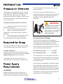
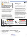
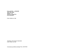
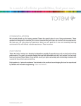
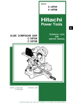
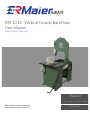
KM 1012 : Vertical Gravity Band Saw User Manual www.ermaiersaws.com ENGLISH FOR MACHINES MFG. AFTER JAN 2010 Manufactured in North America by: Racer Machinery International Inc. V2.0:09.25.2014 KM 1012 TABLE OF CONTENTS 1.01 SAFETY 1.02 Understanding Risks of Machinery ….. 1 1.03 Basic Machine Safety …………………………. 1 1.04 Additional Metal Bandsaw Safety ……… 3 2.01 PREPARATION 2.02 Preparation Overview ……………………….. 4 2.03 Required for Setup …………………………….. 4 2.04 Power Supply Requirements ……………... 4 3.01 EXPLODED DIAGRAMS 3.02 Exploded diagram of Head Assembly … 8 3.03 Exploded diagram of Base Assembly …. 9 4.01 MANUFACTURER DETAILS 4.02 Contact Information ………………………….. 10 SAFETY KM 1012 Understanding Risks of Machinery Operating all machinery and machining equipment can be dangerous or relatively safe depending on how it is installed and maintained, and the operator's experience, common sense, risk awareness, working conditions, and use of personal protective equipment (safety glasses, respirators, etc.). The owner of this machinery or equipment is ultimately responsible for its safe use. This responsibility includes proper installation in a safe environment, personnel training and usage authorization, regular inspection and maintenance and comprehension, application of safety devices, integrity of cutting tools or accessories, and the usage of approved personal protective equipment by all operators and bystanders. The manufacturer of this machinery or equipment will not be held liable for injury or property damage from negligence, improper training, machine modifications, or misuse. Failure to read, understand, and follow the manual and safety labels may result in serious personal injury, including amputation, broken bones, electrocution, or death. The signals used in this manual to identify hazard levels are defined as follows: DANGER Death or catastrophic harm WILL occur CAUTION Moderate injury or fie MAY occur WARNING Death or catastrophic harm COULD occur NOTICE Machine or property damage may occur Basic Machine Safety 1 Owner’s Manual: All machinery and machining equipment presents serious injury hazards to untrained users. To reduce the risk of injury, anyone who uses THIS item MUST read and understand this entire manual before starting. 2 Personal Protective Equipment: Operating or servicing this item may expose the user to flying debris, dust, smoke, dangerous chemicals, or loud noises. These hazards can result in eye injury, blindness, long-‐term respiratory damage, poisoning, cancer, reproductive harm or hearing loss. Reduce your risks from these hazards by wearing approved eye protection, respirator, gloves, or hearing protection. 3 Trained/Supervised Operators Only: Untrained users can seriously injure themselves or bystanders. Only allow trained and properly supervised personnel to operate this item. Make sure safe operation instructions are clearly understood. If electrically powered, use padlocks and master switches, and remove start switch keys to prevent unauthorized use or accidental starting. 4 Guards/Covers: Accidental contact with moving parts during operation may cause severe entanglement, impact, cutting, or crushing injuries. Reduce this risk by keeping any included guards/covers/doors installed, fully functional, and positioned for maximum protection. 1 SAFETY 5 Entanglement: Loose clothing, gloves, neckties, jewelry or long hair may get caught in moving parts, causing entanglement, amputation, crushing, or strangulation. Reduce this risk by removing/securing these items so they cannot contact moving parts. 6 Mental Alertness: Operating this item with reduced mental alertness increases the risk of accidental injury. Do not let a temporary influence or distraction lead to a permanent disability! Never operate when under the influence of drugs/alcohol, when tired, or otherwise distracted. 7 Safe Environment: Operating electrically powered equipment in a wet environment may result in electrocution; operating near highly flammable materials may result in a fire or explosion. Only operate this item in a dry location that is free from flammable materials. 8 Electrical Connection: With electrically powered equipment, improper connections to the power source may result in electrocution or fire. Always adhere to all electrical requirements and applicable codes when connecting to the power source. Have all work inspected by a qualified electrician to minimize risk. 9 Disconnect Power: Adjusting or servicing electrically powered equipment while it is connected to the power source greatly increases the risk of injury from accidental startup. Always disconnect power BEFORE any service or adjustments, including changing blades or other tooling. 10 Secure Work piece/Tooling: Loose work pieces, cutting tools, or rotating spindles can become dangerous projectiles if not secured or if they hit another object during operation. Reduce the risk of this hazard by verifying that all fastening devices are properly secured and items attached to spindles have enough clearance to safely rotate. KM 1012 11 Chuck Keys or Adjusting Tools: Tools used to adjust spindles, chucks, or any moving/ rotating parts will become dangerous projectiles if left in place when the machine is started. Reduce this risk by developing the habit of always removing these tools immediately after using them. 12 Work Area: Clutter and dark shadows increase the risks of accidental injury. Only operate this item in a clean and well-‐lighted work area. 13 Properly Functioning Equipment: Poorly maintained, damaged, or malfunctioning equipment has higher risks of causing serious personal injury compared to those that are properly maintained. To reduce this risk, always maintain this item to the highest standards and promptly repair/service a damaged or malfunctioning component. Always follow the maintenance instructions included in this documentation. 14 Unattended Operation: Electrically powered equipment that is left unattended while running cannot be controlled and is dangerous to bystanders. Always turn the power OFF before walking away. 15 Health Hazards: Certain cutting fluids and lubricants, or dust/smoke created when cutting, may contain chemicals known to cause cancer, respiratory problems, birth defects, or other reproductive harm. Minimize exposure to these chemicals by wearing approved personal protective equipment and operating in a well-‐ventilated area. 16 Difficult Operations: Attempting difficult operations with which you are unfamiliar increases the risk of injury. If you experience difficulties performing the intended operation, STOP! Seek an alternative method to accomplish the same task, ask a qualified expert how the operation should be performed, or contact our Technical Support for assistance. 2 SAFETY KM 1012 Additional Metal Bandsaw Safety 1 Blade Condition. A dull or damaged blade can break apart during operation, increasing the risk of operator injury. Do not operate with a dull, cracked or badly worn blade. Inspect the blade for cracks or missing teeth before each use. 2 Hand Placement. Hands could be cut by the blade or crushed when lowering the headstock. Never position fingers or thumbs in line with the cut or under the headstock while it is moving. 3 Blade Guard. Hands and fingers can easily be cut by the bandsaw blade. To reduce the risk of laceration injuries, do not operate this bandsaw without the blade guard in place. 4 Starting Position. To reduce the likelihood of blade breakage and possible entanglement, never turn the saw ON with the blade resting on the workpiece. 5 Blade Replacement. The blade can only make a safe and efficient cut if the teeth are facing the workpiece. When replacing blades, make sure the teeth face toward the workpiece. Wear gloves to protect hands and safety glasses to protect eyes. 6 Workpiece Handling. A shifting workpiece can result in impact or laceration injuries. To reduce the risk of injury, always securely clamp the workpiece in the vise and use additional support fixtures if needed. Never hold the workpiece with your hands during a cut. Flag long pieces to reduce the risk of tripping over them. 7 Power Interruption. Unplug the machine and turn the power switch OFF after a power interruption. If left plugged in and turned ON, this machine will start up when power is restored, resulting in possible entanglement, laceration, or amputation hazards. 8 Hot Surfaces/Sharp Edges. Due to the cutting process, a freshly cut workpiece, chips, and some machine components can be hot enough to burn you and sharp enough to cut you. Allow components to cool and use safe handling methods to reduce the risk of these injuries. 9 Moving Blade. A moving bandsaw blade presents a serious risk for laceration or amputation injuries. Always allow the blade to come to a complete stop before mounting or repositioning a workpiece in the vise. Never touch a moving blade. 3 PREPARATION Preparation Overview The purpose of the preparation section is to help you prepare your machine for operation. The list below outlines the basic process to follow to prepare your machine for operation. Specific steps for each of these points will be covered in detail later in this section. The typical preparation process is as follows: 1 Unpack the machine and inventory the contents of the carton. 2 Clean the machine and its components. 3 Make any necessary adjustments or inspections to ensure the machine is ready for operation. 4 Connect the machine to the power source. 5 Test run the machine to make sure it functions properly and is ready for operation. Required for Setup The items listed below are required to successfully set up and prepare this machine for operation. For Power Connection A power source that meets the minimum circuit requirements for this machine. (Refer to the Power Supply Requirements section for details.) A qualified electrician to ensure a safe and code-‐compliant connection to the power source. Power Supply Requirements Availability Before installing the machine, consider the availability and proximity of the required power supply circuit. If an existing circuit does not meet KM 1012 the requirements for this machine, a new circuit must be installed. To minimize the risk of electrocution, fire, or equipment damage, installation work and electrical wiring must be done by a qualified electrician in accordance with all applicable codes and standards. WARNING Electrocution or fire may occur if machine is not correctly grounded and attached to the power supply. Use a qualified electrician to ensure a safe power connection Full-‐Load Current Rating The full-‐load current rating is the amperage a machine draws at 100% of the rated output power. On machines with multiple motors, this is the amperage drawn by the largest motor or sum of all motors and electrical devices that might operate at one time during normal operations. Full-‐Load Rating at 110V.................. 14 Amps Full-‐Load Rating at 220V.................. 6.8 Amps The full-‐load current is not the maximum amount of amps that the machine will draw. If the machine is overloaded, it will draw additional amps beyond the full-‐load rating. If the machine is overloaded for a sufficient length of time, damage, overheating, or fire may result— especially if connected to an undersized circuit. To reduce the risk of these hazards, avoid overloading the machine during operation and make sure it is connected to a power supply circuit that meets the requirements in the following section. 4 PREPARATION A power supply circuit includes all electrical equipment between the main breaker box or fuse panel in your building and the incoming power connections inside the machine. This circuit must be safely sized to handle the full-‐load current that may be drawn from the machine for an extended period of time. CAUTION For your own safety and protection of property, consult a qualified electrician if you are unsure about wiring practices or electrical codes in your area. Note: The circuit requirements listed in this manual apply to a dedicated circuit—where only one machine will be running at a time. If this machine will be connected to a shared circuit where multiple machines will be running at the same time, consult a qualified electrician to ensure that the circuit is properly sized for safe operation. KM 1012 Grounding Requirements In the event of certain types of malfunctions or breakdowns, grounding provides a path of least resistance for electric current—in order to reduce the risk of electric shock. For 110V Connection (Prewired) This machine is equipped with a power cord that has an equipment-‐grounding wire and a grounding plug (similar to the figure below). The plug must only be inserted into a matching receptacle (outlet) that is properly installed and grounded in accordance with all local codes and ordinances. Circuit Requirements for 110V This machine is prewired to operate on a 110V power supply circuit that has a verified ground and meets the following requirements: Nominal Voltage ............................... 110V/120V Cycle .............................................................60 Hz Phase ..............................................Single-‐Phase Circuit Rating....................................... 15 Amps Plug/Receptacle (included) ...........NEMA 5-‐15 Circuit Requirements for 220V This machine can be converted to operate on a 220V power supply. To do this, follow the Voltage Conversion instructions included in this manual. The intended 220V circuit must have a verified ground and meet the following requirements: Nominal Voltage ............................... 220V/240V Cycle .............................................................60 Hz Phase ..............................................Single-‐Phase Circuit Rating....................................... 15 Amps Plug/Receptacle ...............................NEMA 6-‐15 Figure 2. NEMA 5-‐15 plug and receptacle For 220V Connection Use the plug type listed in the Circuit Requirements for this voltage. The listed plug (similar to the figure below) has an equipment-‐ grounding wire to safely ground the machine. The plug must only be inserted into a matching receptacle (outlet) that is properly installed and grounded in accordance with all local codes and ordinances. Figure 3. NEMA 6-‐15 plug and receptacle 5 PREPARATION KM 1012 replace it with a new one. WARNING Extension Cords Series injury could occur if you connect the machine to power before completing the setup process. DO NOT connect to power until instructed later in this manual. Improper connection of the equipment-‐grounding wire can result in a risk of electric shock. The wire with green insulation (with or without yellow stripes) is the equipment-‐grounding wire. If repair or replacement of the power cord or plug is necessary, do not connect the equipment-‐ grounding wire to a live (current carrying) terminal. Check with a qualified electrician or service personnel if you do not understand these grounding requirements, or if you are in doubt about whether the tool is properly grounded. If you ever notice that a cord or plug is damaged or worn, disconnect it from power, and immediately We do not recommend using an extension cord with this machine. If you must use one, only use it if absolutely necessary and only on a temporary basis. Extension cords cause voltage drop, which may damage electrical components and shorten motor life. Voltage drop increases as the extension cord size gets longer and the gauge size gets smaller (higher gauge numbers indicate smaller sizes). Any extension cord used with this machine must contain a ground wire, match the required plug and receptacle listed in the Circuit Requirements for the applicable voltage, and meet the following requirements: Minimum Gauge Size.............................16 AWG Maximum Length (Shorter is Better)....50 ft WARNING Loose hair, clothing, or jewelry could get caught in machinery and cause serious personal injury. Keep these items away from moving parts at all times to reduce this risk. WARNING During operation, small metal chips may become airborne, leading to serious eye injury. Wear safety glasses to reduce this risk. Manufacturer Details We stand behind our machines. If you have any questions, parts requests or general inquiries about the machine, feel free to contact us. Racer Machinery International Inc. – Manufacturer of E-‐R Maier™ Saws. Headquarters (CANADA) Sales Office (USA) Cambridge, Ontario N3H 4R7 Williamsville, NY 14221 T: +1 (519) 623 6223 T: +1 (716) 462 6224 F: +1 (519) 623 1122 Web: www.ermaiersaws.com 6 KM 1012 : Vertical Gravity Band Saw Exploded Diagrams www.ermaiersaws.com 7 A B C D E F 68 65 3 68 61 72 24 9 55 51 73 6 8 54 32 14 5 63 53 33 12 8 55 50 ITEM PART NUMBER NO. 1 HBOLT 0.3125-18x0.75x0.75-N 2 HBOLT 0.3125-18x1.25x0.875-N 3 HBOLT 0.3125-18x1x0.875-N 4 Heavy LW 0.5 5 HFBOLT 0.25-20x1.25x0.75-N 6 HFBOLT 0.3125-18x1.5x0.875-N 7 HFBOLT 0.3125-18x1x1-N 8 HFBOLT 0.3125-18x2x0.875-N 9 HFBOLT 0.375-16x0.875x0.875-N 10 HFBOLT 0.375-16x1.5x1-N 25 48 30 40 7 51 41 7 26 43 51 72 31 11 59 33 17 DESCRIPTION 60 3 29 14 34 6 6 69 51 67 2 1 5 1 6 2 4 2 4 3 QTY. 8 10 2 56 58 15 16 52 56 40 52 47 19 45 71 37 5 70 36 55 10 51 21 49 ITEM PART NUMBER NO. 11 HFBOLT 0.375-16x1.75x1-N 12 HFBOLT 0.375-16x1x1-N 13 HFBOLT 0.5-13x1x1-N 14 HNUT 0.3125-18-D-N 15 HNUT 0.6250-11-D-N 16 HX-SHCS 0.25-20x1.5x1-N 17 HX-SHCS 0.375-16x0.75x0.75-N 18 HX-SHCS 0.375-16x1.25x1.25-N 19 KM1012-0003 20 KM1012-0017 5 39 57 29 28 50 44 55 1 PROPRIETARY AND CONFIDENTIAL 7 20 51 4 63 64 65 66 67 68 69 70 71 72 73 74 75 3 2 DO NOT SCALE DRAWING FINISH N/A MATERIAL INTERPRET GEOMETRIC TOLERANCING PER: X - +/- 0.1 X.X - +/- 0.1 X.XX - +/- 0.02 DIMENSIONS ARE IN MM TOLERANCES: UNLESS OTHERWISE SPECIFIED: 2 COMMENTS: Q.A. MFG APPR. ENG APPR. CHECKED DRAWN lpop NAME RMI-30024 RMI-30032 RMI-50054 SBHCSCREW 0.164-32x0.375-HX-N SBHCSCREW 0.25-20x0.375-HX-N Selected Narrow FW 0.312 Selected Narrow FW 0.375 SHSSCREW 0.5x1-N SPS 0.25x1.5 SSFLATSKT 0.3125-18x0.625-HX-N SSHDOGSKT 0.375-16x0.625-HX-N Wide FW 0.5 RMI-30042 62 RMI-30023 ITEM PART NUMBER NO. 21 KM1012-0020 22 KM1012-0022 23 KM1012-0024 24 KM1012-0025 25 KM1012-0026 26 KM1012-0027 27 KM1012-0028 28 KM1012-0030 29 KM1012-0031 30 KM1012-1028 31 KM1012-1035 32 KM1012-1042 33 KM1012-1043 34 KM1012-1047 35 KM1012-1048 36 KM1012-1050 37 KM1012-1051 38 KM1012-1052 39 KM1012-1053 40 KM1012-1055 41 KM1012-1056 42 KM1012-1061 43 KM1012-1066 44 KM1012-1067 45 KM1012-1068 46 KM1012-1073 47 KM1012-1074 48 KM1012-1075 49 Preferred Narrow FW 0.375 50 Preferred Wide FW 0.3125 51 Preferred Wide FW 0.375 52 Preferred Wide FW 0.625 53 Regular LW 0.25 54 Regular LW 0.3125 55 Regular LW 0.375 56 RMI-30002 57 RMI-30003 58 RMI-30004 59 RMI-30020 60 RMI-30021 61 RMI-30022 3 1030 Fountain St. N. Cambridge, Ontario, N3H 4R7 Canada Phone: 519-623-6223 Fax: 519-623-1122 www.racerinternational.com 42 74 4 62 13 75 66 46 15 35 38 23 27 57 22 64 62 9 2 4 1 7 2 4 1 1 1 2 QTY. Racer Machinery Int'l Inc. 20 THE INFORMATION CONTAINED IN THIS DRAWING IS THE SOLE PROPERTY OF RACER MACHINERY INTERNATIONAL. ANY REPRODUCTION IN PART OR AS A WHOLE WITHOUT THE WRITTEN PERMISSION OF RACER MACHINERY INTERNATIONAL IS PROHIBITED. 54 74 Head Weldment ASM Guide Roller ASM DESCRIPTION 4 1/30/2014 DATE 1 1 1 2 2 8 2 1 1 2 3 2 1 2 1 1 1 1 1 1 1 1 2 1 1 1 2 1 1 2 1 1 1 4 1 1 1 1 1 1 1 1 1 8 15 2 6 13 9 3 2 1 1 1 1 KM1012-0004 C 1 SHEET 2 OF 2 SCALE: 1:7.5WEIGHT: 121174.42 KM1012-0004 B-46 SIZE DWG. NO. REV Head Assembly (KM1012) TITLE: Racer Machinery International Inc. Saw Blade Bearing 6003DD Bearing 6206DD Bearing 6305DD Gearbox Speed Reducer 40:1 Gear Box Pulley Motor Pulley Rubber Band 3/16"x3/4"x44.5" BLK NEO V Belt 4L290 Name Plate 1HP Electric Motor Top Wheel Mount ASM Fluted Knob ASM - Short Limit Switch Assembly Motor Handle ASM Motor Mount ASM Top Wheel Adj Hoist Handle Bar Weld Wheel Upper + Ret Ring V Roller Assembly Head Frame Wheel Bar Top Wheel Adjuster Plate Top Wheel Adjuster Plate1 Top Wheel Plate Slide Rear Motor Cover Guide Bar Blade Cover Guide Retainer Part A Guide Retainer Part B Guide Bar Bearing Mount Straight Bearing Mount Cam Bearing Mount Cam Lg Drive Wheel Lower1 Gearbox Bushing Bushing Lower Wheel Counterweight Connector Upper Guide Lower Guide Top Wheel Adj Block DESCRIPTION 1 QTY. A B C D E F A B C D E F KM1012-0007 KM1012-0009 KM1012-0010 KM1012-0013 KM1012-0014 KM1012-0015 KM1012-0016 KM1012-0018 KM1012-0032 KM1012-0041 KM1012-2001 KM1012-2013 KM1012-2014 KM1012-2015 KM1012-2017 KM1012-2044 KM1012-2045 KM1012-2046 KM1012-2047 KM1012-2066 KM1012-2067 KM1012-2068 KM1012-2069 KM1012-2071 Narrow FW 0.25 Preferred Narrow FW 0.3125 Preferred Narrow FW 0.5 Regular FW 0.3125 Regular FW 0.375 Regular LW 0.25 Regular LW 0.3125 Regular LW 0.375 RMI-30033 RMI-30034 RMI-30037 RMI-30040 RMI-50081 SHSSCREW 0.5x0.625-N SHSSCREW 0.5x1.25-N SHSSCREW 0.5x1-N SPS 0.25x1.5 Wide FW 0.375 14 15 16 17 18 19 20 21 22 23 24 25 26 27 28 29 30 31 32 33 34 35 36 37 38 42 43 44 45 46 47 48 49 50 51 52 53 54 55 41 40 39 13 8 HX-SHCS 0.25-20x1x1-N HX-SHCS 0.513x1.25x1.25-N KM1012-0002 Base Weldment (KM1012) 11 7 Motor Starter 120V 1 HP Knob 35mm Dia 3/8-16 UNC E-R Maier Ruler Swivel Caster 4" x 1.5" Rollx Rigid Caster 4" x 1.5" Rollx .375-16UNC THRD_ROD Pedal Lock Angle Table Side Frame Rail Frame Rail Beveled Handle Handle Roller Handle Bushing Handle Connector Bar Ruler Plate Spacer Table Front Saw Table Ruler Stop Washer Square Counterweight Arms ASM Duplex Receptacle Assembly Mitre Block ASM Tray ASM Counterweight ASM Handle Inside Arm Asm C Clamp ASM Guide Bar ASM Foot Pedal ASM Limit Block ASM HNUT 0.3750-16-D-N 10 12 HNUT 0.3125-18-D-N 9 DESCRIPTION HNUT 0.2500-20-D-N PART NUMBER HBOLT 0.312518x0.875x0.875-N HFBOLT 0.2520x0.875x0.875-N HFBOLT 0.312518x1.25x0.875-N HFBOLT 0.312518x2x0.875-N HFBOLT 0.5-13x1.5x1.25N HHBOLT 0.500013x2.5x1-N HJNUT 0.3750-16-D-N 7 8 7 6 5 4 3 2 1 ITEM NO. 8 1 1 1 1 1 1 1 1 2 2 2 16 2 1 1 1 16 2 4 1 1 1 1 1 1 1 1 1 2 1 1 10 1 1 1 1 1 1 1 1 1 1 1 2 1 8 18 1 2 4 2 1 1 2 17 QTY. 6 6 12 5 34 35 9 45 48 24 27 3 14 11 8 25 42 4 5 33 5 22 26 13 16 6 4 THE INFORMATION CONTAINED IN THIS DRAWING IS THE SOLE PROPERTY OF RACER MACHINERY INTERNATIONAL. ANY REPRODUCTION IN PART OR AS A WHOLE WITHOUT THE WRITTEN PERMISSION OF RACER MACHINERY INTERNATIONAL IS PROHIBITED. PROPRIETARY AND CONFIDENTIAL 46 4 3 1030 Fountain St. N. Cambridge, Ontario, N3H 4R7 Canada Phone: 519-623-6223 Fax: 519-623-1122 www.racerinternational.com 41 Racer Machinery Int'l Inc. 47 55 18 3 9 DO NOT SCALE DRAWING FINISH _ MATERIAL INTERPRET GEOMETRIC TOLERANCING PER: X - +/- 0.1 X.X - +/- 0.1 X.XX - +/- 0.02 DIMENSIONS ARE IN MM TOLERANCES: UNLESS OTHERWISE SPECIFIED: 44 39 51 2 COMMENTS: Q.A. MFG APPR. ENG APPR. CHECKED DRAWN 20 2 1 lpop NAME 16 1/21/2014 DATE 43 2 36 23 19 1 21 37 50 29 30 53 52 40 15 7 17 31 32 49 54 28 KM1012-0001 C 1 SHEET 2 OF 2 SCALE: 1:11 WEIGHT: 169995.16 KM1012-0001 B-43 SIZE DWG. NO. REV Base Assembly (KM1012) TITLE: Racer Machinery International Inc. 38 1 A B C D E F KM 1012 Manufacturer Details We stand behind our machines. If you have any questions, parts requests or general inquiries about the machine, feel free to contact us. Racer Machinery International Inc. – Manufacturer of E-‐R Maier™ Saws. Headquarters (CANADA) Cambridge, Ontario N3H 4R7 T: +1 (519) 623 6223 F: +1 (519) 623 1122 Web: www.ermaiersaws.com Sales Office (USA) Williamsville, NY 14221 T: +1 (716) 462 6224 10