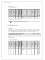
1
MPTP | Copyrights and limitation of liability 1 Mobile Phone Telematics Protocol for TWIG GSM/GPS products Version 3.25 Licensed to:Twig Com Ltd., SALO, FI Copyright Twig Com Ltd. All rights reserved Version 3.25 Rev. September 6 2012 ’ CONFIDENTIAL. Copyright Twig Com Ltd. 2007-2012. All rights reserved. | Version 3.25 | Rev. September 6 2012 Licensed to: Twig Com Ltd., SALO, FI MPTP | Copyrights and limitation of liability 2 LIMITED LICENSE AGREEMENT Licensee: Licensee contact person: The licensor, Twig Com Ltd., Meriniitynkatu 11, FIN-24100 Salo, Finland, Tel +358 40 510 5058, hereby grants the licensee a limited license to use this TWIG MPTP Document solely for the Purpose of integrating TWIG devices by Twig Com Ltd. to third party software. Any other use is expressly prohibited. By accepting or using any part of this Document the Licensee agrees to the terms of this Limited License Agreement. COPYRIGHTS AND OTHER IPR RETAINED All copyrights and other intellectual property rights in this Twig Com Ltd. TWIG MPTP Document are and remain sole property of Twig Com Ltd.. This Document is for information only and no right to use the commands are hereby given unless it is licensed version and user is licensee. NON-DISCLOSURE The licensee shall not disclose any part of this Document to its personnel or third parties without a need to know for implemetation of Purpose. The licensee shall require from third parties with need to know a standard of non-disclosure and protection of Twig Com Ltd. IPRs no less stringent than it is applying itself. Any copies of Document not needed for Purpose shall be promptly destroyed. LIMITATION OF LIABILITY Twig Com Ltd. TWIG MPTP Document is distributed "as is" and the user will assume full responsibility for determining the suitability of the license for any particular purpose and for desired results. In no event shall Twig Com Ltd. be liable for any special, incidental or consequential damages, or commercial losses from any cause including but not limited to, loss of profit or revenues, whether or not Twig Com Ltd. has received notice of a possibility or certainty of such damage or losses, caused by use of or operation with Twig Com Ltd. TWIG MPTP Document. DAMAGES Twig Com Ltd. reserves the right to demand license fees and/or damages in case this Document is used unrightfully. MORE INFORMATION Please contact Twig Com Ltd. Sales Office [email protected], or phone +358 40 510 5058. [email protected], or Technical Support Twig Com Ltd. reserves full rights to make any changes to document without prior notice. CONFIDENTIAL. Copyright Twig Com Ltd. 2007-2012. All rights reserved. | Version 3.25 | Rev. September 6 2012 Licensed to: Twig Com Ltd., SALO, FI MPTP | Table of contents 3 TABLE OF CONTENTS 1. INTRODUCTION............................................................................................................................................................... 5 2. OVERVIEW OF THE SYSTEM......................................................................................................................................... 6 2.1. Actors............................................................................................................................................................ 6 2.1.1. Control Centre.............................................................................................................................. 6 2.1.2. Mobile Telematics Terminal.........................................................................................................6 2.1.3. Authorisation and access rights...................................................................................................7 2.2. Applications................................................................................................................................................... 8 2.2.1. Position reporting......................................................................................................................... 8 2.2.2. Tracking....................................................................................................................................... 9 2.2.3. Emergency cycle........................................................................................................................10 2.2.4. Status and information messages..............................................................................................10 2.2.5. Device configuring..................................................................................................................... 10 2.2.6. Generic response messages.....................................................................................................11 3. MESSAGE CONSTRUCTION AND INTERPRETATION...............................................................................................13 3.1. Common fields............................................................................................................................................ 13 3.2. Reading an MPTP command......................................................................................................................17 3.3. Reassembling a received MPTP command................................................................................................18 3.4. Encryption................................................................................................................................................... 18 3.5. Transliteration............................................................................................................................................. 18 3.6. Base64 encoding........................................................................................................................................ 19 3.7. Table of MPTP commands..........................................................................................................................19 4. MPTP COMMANDS........................................................................................................................................................ 20 4.1. Position reporting commands......................................................................................................................20 4.1.1. Position request (?LOC)............................................................................................................20 4.1.2. Position report (!LOC)................................................................................................................23 4.1.3. SRD Beacon reports.................................................................................................................. 24 4.2. Tracking commands.................................................................................................................................... 26 4.2.1. Tracking requests from Control Centre......................................................................................27 4.2.1.1. Simple tracking request: interval, minutes (?TRC)................................................27 4.2.1.2. Simple tracking request: interval, seconds (?TRS)................................................29 4.2.1.3. Simple tracking request: stopping interval tracking (?STO)...................................31 4.2.1.4. Complex tracking request (?TRG).........................................................................32 4.2.1.4.1. Trigger type 0: area tracking...............................................................................33 4.2.1.4.2. Trigger type 1: stopping at report limit................................................................36 4.2.1.4.3. Trigger type 2: stopping at time limit...................................................................37 4.2.1.4.4. Trigger type 3: stopping at date and time...........................................................39 4.2.1.4.5. Trigger type 7: endless tracking..........................................................................40 4.2.1.4.6. Trigger type 9: anchor tracking...........................................................................42 4.2.1.4.7. Deactivating complex tracking............................................................................43 4.2.1.5. Real time complex tracking request (?TRR)..........................................................44 4.2.1.5.1. Trigger type 7: endless tracking..........................................................................46 4.2.1.5.2. Deactivating real time complex tracking.............................................................47 4.2.2. Tracking reports......................................................................................................................... 48 4.2.2.1. Simple report: interval tracking, minutes (!TRC)....................................................49 4.2.2.2. Simple report: interval tracking, seconds (!TRS)...................................................51 4.2.2.3. Complex report: tracking triggers (!TRG)...............................................................52 4.2.2.4. Real time complex report: tracking triggers (!TRR)...............................................54 4.3. Condition check commands........................................................................................................................56 4.3.1. Condition check report (!CIN)....................................................................................................57 CONFIDENTIAL. Copyright Twig Com Ltd. 2007-2012. All rights reserved. | Version 3.25 | Rev. MMMM d, yyyy Licensed to: Twig Com Ltd., SALO, FI MPTP | Table of contents 4 4.3.2. Acknowledgement to condition check permission request........................................................59 4.4. Emergency cycle commands......................................................................................................................60 4.4.1. Emergency report with text (!EMG)............................................................................................61 4.4.2. Emergency confirmation (?EMG)...............................................................................................62 4.5. Status and information commands..............................................................................................................63 4.5.1. Status report (!STA)...................................................................................................................64 4.5.2. Assistance request (!ASS).........................................................................................................65 4.5.3. Device information report (!INF).................................................................................................66 4.5.4. General indication (!IND)...........................................................................................................68 4.5.5. Automatic status reporting request (?ASR)...............................................................................70 4.5.6. Deactivating automatic status reporting.....................................................................................72 4.5.7. Automatic status report (!ASR)..................................................................................................73 4.5.8. SW version and IMEI request (?SIR).........................................................................................74 4.5.9. SW version and IMEI report (!SIR)............................................................................................75 4.5.10. ON-SCREEN MESSAGE.........................................................................................................76 4.6. Persistent setting configuring (?CNF).........................................................................................................78 4.6.1. Setting 0044: emergency numbers............................................................................................79 4.6.2. Setting 0050: authorized numbers.............................................................................................81 4.6.3. Setting 0060: GPS operating mode...........................................................................................82 4.6.4. Setting 0300: GPRS Telematics settings...................................................................................83 4.6.5. Setting 0301: GPRS Telematics APN........................................................................................84 4.6.6. Setting 0302: GPRS server settings..........................................................................................86 4.6.7. Setting 0303: Timer settings......................................................................................................86 4.6.8. Settings 2001–2009 -General Settings......................................................................................88 4.6.9. Settings 2020–2021 -GPS Settings...........................................................................................89 4.6.10. Settings 2101–2105 –Information messaging..........................................................................90 4.6.11. Settings 2201–2205 –TWIG SOS settings...............................................................................90 4.6.12. Settings 2211–2214 –TWIG SOS profile settings....................................................................91 4.6.13. Settings 2301–2399 –TWIG SOS event data settings.............................................................92 4.6.14. Settings 2400–2423 –TWIG SOS Cycle settings.....................................................................95 4.6.15. Settings 2430–2431 –TWIG SOS Post emergency cycle........................................................96 4.6.16. Settings 2440–2446 –TWIG SOS Man Down Alert.................................................................97 4.6.17. Settings 2500–2510 –GPRS Settings......................................................................................98 4.6.18. Settings 2550–2557 –Assistance call numbers.......................................................................99 4.6.19. Settings 2601–2754 –White list numbers..............................................................................100 4.7. Persistent setting request (?PSR).............................................................................................................105 4.8. Persistent setting report (!PSR)................................................................................................................ 106 4.9. Reset terminal request (?RST)................................................................................................................. 107 CONFIDENTIAL. Copyright Twig Com Ltd. 2007-2012. All rights reserved. | Version 3.25 | Rev. MMMM d, yyyy Licensed to: Twig Com Ltd., SALO, FI MPTP | MPTP commands 1. 5 INTRODUCTION MPTP (Mobile Phone Telematics Protocol) is a protocol developed by Twig Com Ltd. . It is a key for building professional and consumer telematics solutions in GSM networks. MPTP provides sophisticated telematics commands for service integrators and providers to build and provide various applications utilising location information. MPTP enables, for example, the sending of location, tracking and route messages between service centers and Twig Com Ltd. MPTP enabled terminals. It uses SMS as bearer, and is fast and easy to implement in service centers. Application examples • navigational directions • geomessaging and mobile communities • yellow pages with turn-by-turn instructions • points of interest • location-sensitive sponsored content • fleet management • staff management • personal safety • security • healthcare • sports and lifestyle What about privacy? There is general concern about privacy issues with the new location-based services. Can anybody track my location through MPTP? TWIG wireless instruments targeted for consumer markets require the consent of the user for his position to be revealed to other persons or to services. Products targeted at vertical business or organisational applications may be configured to authorize the service center to track the device. This is essential for e.g. providing back-up safety to lone workers or tracking valuable assets. For further information If you have any questions, please pay a visit to our web pages. You will also find our contact information there. http://www.twigworld.com MPTP | MPTP commands 2. 6 OVERVIEW OF THE SYSTEM MPTP messaging takes place in the GSM network using specially formatted SMS messages. This chapter describes the roles of the actors in such MPTP messaging exchange and gives an overview of some typical scenarios involving telematics messaging. A more detailed and technical description of the format, structure and use of MPTP commands is given in subsequent chapters. 2.1. Actors MPTP messaging always takes place between two parties. The typical actors in such exchange are a Control Centre and a Mobile Telematics Terminal. 2.1.1. Control Centre A Control Centre has capabilities for monitoring and controlling one or more Mobile Telematics Terminals. Such remote controlling functionality includes requesting and receiving position updates from terminals, creating navigation objects such as waypoints and routes on them, configuring the terminals’ setup, and receiving and distributing status information. A Control Centre is typically a PC equipped with hardware and software (such as Benefon In Charge) for sending, receiving and processing MPTP messages. An MPTP-enabled mobile instrument such as Benefon Esc! also features functions for acting as a Control Centre with less extensive capabilities. In subsequent chapters, the Control Centre will often be referred to as CC. 2.1.2. Mobile Telematics Terminal A Mobile Telematics Terminal is a positioning-capable mobile instrument with functionality for receiving and responding to MPTP messages sent by the Control Centre. Its typical uses include sending position information (e.g. when it is tracked) and sending status messages. Typical Mobile Telematics Terminals include professional work management instruments such as Benefon Track, navigation instruments such as Benefon Esc!, and asset tracking instruments such as Benefon TrackKeeper. Depending on situation, a Mobile Telematics Terminal may sometimes also act as a Control Centre. An example of such a case is when a Benefon Esc! is used for both tracking other terminals (in which case it acts as a Control Centre) as well as responding to requests from them (in which case it acts as a Mobile Telematics Terminal). In subsequent chapters, the Mobile Telematics Terminal will often be referred to as MTT. MPTP | MPTP commands 7 2.1.3. Authorisation and access rights It is desirable to limit the parties from which MPTP messages used for controlling and monitoring a Mobile Telematics Terminal are allowed, not only to protect the user’s privacy and to ensure security of stored data, but also to limit the number of messages sent. Track and Esc! use a somewhat different system for controlling MPTP messaging. Benefon Track In the Track line of products, the setting Service center number defines one number which has full rights for remotely controlling and configuring all features of the instrument. All requests sent from this number are always responded to immediately. The setting Authorization determines whether the list of Authorized numbers should be used for deciding whether a request should be processed and responded to. Please note that this also applies to configuration request commands. • • If Authorization is enabled: - All requests from authorized numbers are automatically processed. Any responses are sent to the number from which the request came. - All requests from numbers not listed as authorized are either disregarded altogether or require the user to accept their processing by confirming a notification; the exact actions taken depend on the command in question. Any responses are sent to the number from which the request came. If Authorization is disabled: - All requests are automatically processed. If the Service center number has been defined, any responses are always sent to that number; otherwise, they are sent to the number from which the request came. The phone numbers defined as Emergency center numbers (Telematics settings > Emergency settings > Emergency center numbers) are treated as authorized numbers. However, please note that some products such as Benefon Seraph do not treat the emergency center numbers as authorized except during emergency situations. Benefon Esc! In the Esc! line of products, the Friend Find or Commander application can be used for marking the Friend Find entries as authorized or unauthorized. • All requests from authorized Friend Find entries are automatically processed. Any responses are sent to the number from which the request came. • All requests from unauthorized Friend Find entries require the user to accept their processing by confirming a notification. Any responses are sent to the number from which the request came. Esc! does not support reception of configuration request commands. Twig Hunter In the Twig Hunter line of products, the Twig Hunter application can be used for marking the target entries as authorized or unauthorized. • All requests from authorized target entries are automatically processed. Any responses are sent to the number from which the request came. MPTP | MPTP commands • 8 All requests from unauthorized target entries require the user to accept their processing by confirming a notification. Any responses are sent to the number from which the request came. Twig Discovery Pro In the Twig Discovery Pro line of products, the Twig Configurator PC-application can be used for marking the partners as authorized or unauthorized. • All requests from authorized partners are automatically processed. Any responses are sent to the number from which the request came. • All requests from unauthorized partners require the user to accept their processing by confirming it in Twig Inbox application. Any responses are sent to the number from which the request came. The phone numbers defined for Twig SOS application are treated as authorized numbers while Twig SOS application is active. 2.2. Applications MPTP provides a wide set of commands for realising the application examples listed in chapter 1. The commands can be categorised according to their type as is done below; this categorisation will be used throughout this document. It should be noted that all report commands typically contain the sending instrument’s position information. 2.2.1. Position reporting The simplest method of sharing the position information of a Mobile Telematics Terminal is by using positioning commands. Typical positioning scenarios are as follows: 1. A Control Centre wants to know the position of a Mobile Telematics Terminal. Examples: (1) A parent wants to know the whereabouts of her child. (2) The shift manager of a taxi company wants to know the position of a car in the field. The centre sends a position request MPTP command to the terminal. The terminal then responds by sending a position report MPTP command which contains its position information. 2. A Mobile Telematics Terminal wants to inform a Control Centre of its position. Example: A security guard informs the alarm centre of his position before entering a dangerous area. The terminal sends a position report MPTP command to the centre. 3. A Control Centre wants to know where a Mobile Telematics Terminal has been. Examples: (1) A probation officer wants to know where the offender has been moving lately. (2) A hunter wants to know where his dog has been moving while chasing a deer. The centre sends a position history request MPTP command to the terminal. The terminal then responds by sending a position history report MPTP command, which contains the requested number of known positions with times. MPTP | MPTP commands 9 The MPTP commands, which can be used for realisation of these scenarios, are described in section 4.1. 2.2.2. Tracking The term tracking means a function, which enables monitoring a target’s position and possible movement. The tracked Mobile Telematics Terminal will automatically send a series of MPTP messages of its position to the Control Centre as defined by the tracking process. Typical tracking scenarios are as follows: 1. A Control Centre wants to follow the movements of a Mobile Telematics Terminal. Examples: (1) A delivery company wants to monitor the movements of a valuable transport. (2) A hunter wants to know how his dog moves in the forest. The centre sends a tracking request MPTP command to the terminal, requesting the terminal to send tracking report MPTP commands at regular intervals. The centre can specify the number of reports it wants to be sent, or it can set a duration or end time for the tracking process. Setting timing for a single report is also possible. 2. A Control Centre wants to be informed when a Mobile Telematics Terminal enters or exits an area. Examples: (1) An electricity company wants to know when a team of electricians arrives at a storm damage area and when it departs from there. (2) A parent wants to know when her child crosses the border of a permitted area. The centre sends a tracking request MPTP command requesting the terminal to send one or more tracking report MPTP commands when it enters and/or exits an area. The centre can specify whether it wants to receive just one report, or get reports at regular intervals while the target is inside or outside the area. 3. A Control Centre wants to be informed when the speed of a Mobile Telematics Terminal goes over or under a limit. Example: A delivery company wants to know when a valuable transport is on the move or when it stops. The centre sends a tracking request MPTP command requesting the terminal to send one or more tracking report MPTP commands when its speed goes over or under the specified limit. 4. A Mobile Telematics Terminal wants to inform a Control Centre of its movements. Example: A social worker wants to keep his shift manager knowledgeable about his movements when entering a dangerous area. The terminal sends a tracking request MPTP command to the centre, requesting its permission to start sending tracking reports. The centre can accept or reject the request by sending an acknowledgement MPTP command. If the request was accepted, the terminal will start sending tracking report MPTP commands as it declared in its request. The MPTP commands, which can be used for realisation of these scenarios, are described in section 4.2. Entering and exiting an area can also be monitored by using the travel mark commands; cf. below. MPTP | MPTP commands 10 2.2.3. Emergency cycle The term emergency cycle refers to an automated sequence of actions taken when the end user has pressed the emergency key. External triggers such as a verticality sensor can also start the cycle. The action sequence consists of making emergency calls and sending emergency messages containing position information. Examples: (1) An elderly gentleman falls and injures himself; pressing the emergency key causes sending an emergency report to his daughter and sets up a call. (2) A police officer is shot and down; the verticality sensor starts the emergency cycle, which reports his position to the alarm centre and sets up a call so that the centre can listen to the situation. The emergency cycle functionality is started when the user of a Mobile Telematics Terminal presses the emergency key or when an external event causes it. The terminal will then make a series of phone calls to predefined phone numbers. It will also send emergency report MPTP messages which contain the position of the terminal. The Control Centre receiving such a report may respond by sending an emergency confirmation MPTP command to let the user of the terminal know that the report has been processed. The emergency cycle can also be configured so that it does not stop until emergency confirmation MPTP command has been received. The MPTP commands used for the emergency cycle are described in section 4.4. 2.2.4. Status and information messages Status and information commands are used for reporting a Mobile Telematics Terminal’s or its user’s status information to a Control Centre. 2.2.5. Device configuring The term Device configuring refers to changing or requesting the settings of a Mobile Telematics Terminal by use of an MPTP command sent by a Control Centre. Typical scenarios involving device configuring are as follows: 1. A Control Centre wants to change the settings of the Mobile Telematics Terminal. Examples: (1) The alarm centre wants to start using the message encryption system in the guards’ terminals (2) The emergency centre operator wants to modify the list of emergency calls which will be made when user presses the emergency key of his terminal; rather than have the user reprogram the terminal, the operator sends a configuration command which does the job. The Control Centre sends a persistent settings configuring request MPTP command requesting the terminal to modify its settings accordingly. 2. A Control Centre wants to request the settings of the Mobile Telematics Terminal. Examples: (1) The alarm centre wants to check what is the default location request action used in the guards’ terminals. (2) The emergency centre operator wants check the list of emergency calls which will be made when user presses the emergency key of his terminal. The Control Centre sends a persistent settings request MPTP command requesting the terminal to send its settings. The terminal then sends the persistent settings report containing the requested settings values. MPTP | MPTP commands 3. 11 A Control Centre wants to activate the telematics services of the Mobile Telematics Terminal. Examples: (1) The customer of the emergency services has paid for the service and wants to start using the service. The emergency centre operator activates the telematics services of the customer’s terminal after the customer has paid for the service. After that the emergency cycle feature and rest of the telematics services of the terminal can be used. The Control Centre sends a activation of telematics services request MPTP command requesting the terminal to activate the telematics services. If activation was successful the terminal then sends the activation of telematics services report to the Control Centre. The report contains the IMEI code and the User id of the terminal. The MPTP commands used for remote configuration are described in section 4.6 2.2.6. Generic response messages The instrument receiving an MPTP command may respond by sending a command to acknowledge the reception. Typical scenarios involving generic response messages are as follows: 1. A Mobile Telematics Terminal wants to activate a process (e.g. a tracking process, a condition check process or a route tracking process) but needs the permission of the Control Centre. The terminal sends an activation request (e.g. a tracking request or a condition check request) to the centre. The centre can respond by sending an acknowledgement MPTP command indicating acceptance or rejection of the request. 2. A Control Centre sends a trace log management request to a Mobile Telematics Terminal for downloading the trace log and expects to receive information about errors, if any. The centre sends a request (e.g. a trace log management request command) to the terminal. If the downloading of the trace fails for some reason, the terminal responds by sending an error report MPTP command indicating the cause of the failure. Some terminals may be configured to report successful processing of a request as well. The acknowledgement MPTP command is used for this purpose. The MPTP commands used for generic response messages are described in section 4.5. MPTP | MPTP commands 3. 12 MESSAGE CONSTRUCTION AND INTERPRETATION As mentioned earlier, MPTP messages are sent between parties as specially formatted SMS messages. The standard 7-bit GSM character set is used (cf. GSM 7-bit default alphabet table.pdf). Most MPTP messages are sent in a semi-readable ASCII format and can thus be received and read using any SMS enabled mobile phone. However, manually interpreting the data content of an MPTP message is rather tedious, so the receiving instrument should be equipped with software for reacting to the messages and their data content appropriately. Some of the messages are partly binary and Base64 encoded (cf. 3.6) so that more data can be fitted into one message. Unlike other MPTP messages, AGPS (Assisted GPS) messages are always sent in unreadable binary format. The instrument receiving such a message always needs to have suitable software for interpreting them properly. Binary AGPS messages are treated in MPTP AGPS messages.pdf. The later sections of this document list all MPTP commands. For each command, its usage and format is given, along with a list of the Benefon or TWIG instruments which are equipped with software for using the command in question. 3.1. Common fields As mentioned above, most of MPTP messages sent in ASCII format is a semi-readable string, like the example below: !TRG_01/01_4_1_norm_075%_gps_2_N68.28.43,9_E027.27.02,4_37_ 08.07.2003_17:44:23_081km/h_114deg_81 (For the curious, the above command is sent by a tracking process with a trigger for sending messages when the speed limit of 81 km/h is exceeded.) An MPTP command consists of a number of fields with different meanings. The fields can be found by looking for field separator characters which separate them; the underscore character (_, Unicode 0x5F) is used for this purpose. Note that the underscore character should not be used at middle of any string fields. It should also be noted that the data in the command is case sensitive, so care should be taken to use uppercase and lowercase letters as described in this document. Some fields are common to several MPTP commands while others are specific to a command type. The following table uses the sample command above for describing some fields commonly used in several MPTP command types. Field Description !TRG Command A unique string of three to four characters which identifies the purpose of the command and tells how the rest of it should be read. Note that these characters should always be written with capital letters. The first character of the command is by default a question mark or an exclamation mark. The former (?) identifies the role of the sender of the message as a Control Centre, while the latter (!) identifies it as a Mobile MPTP | MPTP commands 13 Telematics Terminal. If for some reason messages which have exclamation and/or question mark as first character do not work in some network, there is a possibility to change the header characters. It is recommended though that the header characters are changed only if the default ones do not work. Note also that if the header characters are changed it should be done to all the terminals which are connected to the same system. There is a setting by which the header characters can be changed. Note that the question and exclamation mark should not be interchanged. In this example, the sender’s role is Mobile Telematics Terminal (!). The command is a tracking update (TRG). 01/01 Part number Sometimes, the MPTP command may need to be sent in several parts. The part number consists of the part number of the message, a slash character, and the total number of parts which make up the complete command. Please refer to Reassembling a received MPTP command (3.3) for more information on reassembling a message received in several parts. Many commands omit this field altogether as they are always sent in one part. In this example, the message consists of one part. The two fields which follow are specific to the !TRG command. Having identified the command as !TRG, the instrument which receives the message can interpret the fields as Trigger type with value “4”, and Service state with value “1”. These values indicate that the event, which triggered the sending of the tracking update command, was exceeding a speed limit. The command then continues with common fields, as follows. norm Mode A four-character string identifying the mode the instrument is in: norm for normal mode, emer for emergency mode, and test for testing mode. Only selected commands ever use modes other than norm. In this example, the instrument is in normal mode. 075% Battery level Three digits and a percentage character, indicating the battery level of the instrument. The battery voltage can also be sent as millivolts. This is doen by sending 4 number code e.g. 3897 = 3.897V In this example, 75% of battery charge is left. gps Position source A three-character string identifying the source of the position in the message (cf. below): gps for GPS. Position is aquired from GPS and the timestamp is related to actual aquisaition time MPTP | MPTP commands 14 gpa, position is aquired from GPS, but the timestamp is updated, since no movement is detected with motion sensor after last actual position fix. Note the motion sensor parameters, that define the needed movement. gpb position is aquired from GPS, but the timestamp is NOT updated, since movement is detected with motion sensor but not calculated by gps. Note the motion sensor parameters, that define the needed movement. net for GSM network. Most commands always assume GPS to be the position source. In this example, the position has been acquired from the GPS receiver with valid fix from receiver. It is stored as coordinates in the Position field. 1 Position format A digit indicating the position format in which the position information in the message is given: 1 for WGS-84, and 2 for WGS-84 with precision. If the position format is 2 (WGS-84 with precision) a field named Position precision will be located after the Position field. Otherwise it will not be present at all, this means that also the underscore characters are missing. !GNR and !EGN always use position format 1 regardless of the value of the setting. Position format 2 (WGS-84 with precision) is not used with !GNR and ! EGN because of lack of space in one SMS. Note that position format 2 is supported only by Track NT versions of the terminals. If the position format is 3 (WGS84 with SRD beacon data) datafield in the end of the message will contain information on surrounding SRD Beacons. N68.28.43,9_ E027.27.02,4 Position Instrument’s last known position at the time of sending of the message. It’s contents depend on the Position source: • If the position source is gps, this field contains the coordinates of the position. The Position format field determines the format used for them. For WGS-84, latitude and longitude are given in degrees, minutes, seconds and fractions of seconds, with a letter indicating the hemisphere (N, S, W, E) preceding the numbers. A single field separator character (_) separates the latitude and the longitude sub-fields. Currently, TWIG instruments do not support position formats other than WGS-84. • If the position source is net, this field is replaced by another one containing network measurement data, which can be used to roughly determine the instrument’s position. In this example, the latitude and longitude of the last known position are N 68°28’43.9” and E 027°27’02.4”, respectively. 37 Position precision MPTP | MPTP commands 15 The precision of the position given in the Position field. The unit for the precision is always meters. The range of the field is 0…255 meters . Values more than 254 are always indicated with 255 in the field. The precision is estimation calculated from multiple variables. Note that this field is present only if the Position format is 2 (WGS-84 with precision) (cf. above) In this example, the position precision has been 37 meters. 08.07.2003 _17:44:23 Time stamp Date and time of the position given in the Position field. UTC (Universal Coordinated Time, or Greenwich Mean Time) is always used, so the receiving instrument needs to do a conversion to local time. A single field separator character (_) separates date and time sub-fields. In this example, the position has been acquired on July 8th, 2003, at 17:44:23. The GPS receiver also provides the UTC time. 081km/h Speed Instrument’s speed at the time when the position was acquired. The last four characters indicate the units used for speed, while the remaining three are used for the numeric speed value. The possible numeric values are 0-999. Currently, TWIG instruments do not support units other than kilometers per hour (km/h), so the receiving instrument needs to do the conversion to other units. This field is omitted if the position source is net, as speed cannot be calculated from GSM network measurement data. In this example, the instrument has been moving at the speed of 81 kilometers per hour. 114deg Heading Three digits and the string deg, indicating the compass direction of movement of the instrument at the time when the position was acquired. This field is omitted if the position source is net, as heading cannot be calculated from GSM network measurement data. In this example, instrument has been moving to the compass direction 114°, i.e. approximately Southeast. The single field which follows is again specific to the !TRG command. Having identified the command as !TRG, the instrument which receives the message can interpret the field as Data with value “81”. In this example, this value indicates that the speed of the instrument at the time of the exceeding of the speed limit was 81 km/h. MPTP | MPTP commands 16 If data needed for a data field is unavailable, the field is commonly filled with hyphen characters (-, Unicode 0x2D). This is the case for the Position, Time stamp, Speed and Heading fields. Reading an MPTP command 4 1 5 1 4 1 4 1 3 1 1 1 24 1 Heading Speed Time stamp Position Position format Position source Battery level Mode Command Part number This document lists each MPTP command as a table, as follows: 19 1 7 1 6 1 3 Additional text Status text 1 Time of sending !STA _ 01/01 _ norm _ 032% _ gps _ 1 _ N60.26.54,3_ _ 11.07.2003 _ 142km/h _ 275deg _ E022.17.37,1 _09:57:46 Status code 3.2. 0…15 1 0…30 1 19 009 _ Everything ok _ On spot _ 11.07.2003 _09:58:03 As stated above, the exact set of fields appearing in an MPTP message depends on the command in question. Fields, which are optional for a command and may be omitted, are listed in the table with dark grey. If the field to be omitted is the last field of the command, it can be simply left out along with the field separator character, which precedes it. However, omitting a field from the middle of a command requires retaining both field characters around it. There will then be two field separators next to each other with nothing between them. The second row in the table lists the length of each field. In some cases, ranges such as 0…14 are given, in which case the length of the field can vary between the given values. Also the field separator characters can be found in the table. An MPTP message should always be read from left to right, reading the value of a field (or its sub-fields) until a field separator character (underscore) is encountered. This is important as the fields often do not have a fixed length, and attempting to read a field in the message by relying on a certain offset may give undesired results. It should also be noted that, even for a field with zero characters, both field separator characters around it still need to be present. TWIG instruments always stop reading a field when its maximum length is reached. Thus, care should be taken not to write too long fields in an MPTP message as the instrument will expect the next field to start directly after the assumed end of the previous field. MPTP | MPTP commands 17 The exact meaning of each field, along with the typical actions taken on reception of the message, is given for each command in this document. 3.3. Reassembling a received MPTP command An instrument receiving an MPTP command in several parts needs to store the parts in a buffer until all of them have been received. As soon as the full set (01/NN, 02/NN, … , NN/NN) is present, the command can be reassembled and processed. Please note that depending on the GSM network used, the parts may not always arrive in the order in which they were sent. Moreover, some GSM networks may cause delays in delivering some parts, and losing parts altogether is not unheard of. These things are caused by the GSM network used and affect all short messages, not only MPTP messages. However, they need to be taken into account when reassembling the command. TWIG instruments feature an internal buffer for storing the parts of an MPTP command and automatically perform the reassembly as soon as all parts have been received. Receiving another command of the same type clears the previous parts from the buffer. 3.4. Encryption The TWIG Message Encryption System is a solution for securing SMS communication. The system provides secure end-to-end data transmission for SMS and location and telematics messages, and makes it virtually impossible to obtain message unauthorised. The encryption also enables the secure identification and authentication of the message sender. Cf. Benefon message encryption system.pdf for detailed information about the solution. 3.5. Transliteration Some of the TWIG terminals support UCS2 characters in the user interface and with this support messages can be written also with Cyrillic, Greek and Hebrew characters. As already mentioned earlier MPTP messages use the 7-bit GSM character set. This set does not include the Cyrillic, Greek or Hebrew characters, so for example status messages written with Cyrillic characters cannot be used if transliteration is not done. All user editable strings which are added to MPTP messages are transliterated before sending the message. For Cyrillic and Greek characters standard transliteration is done. Hebrew characters are mapped one to one to small Latin characters and all Latin characters are written with capital letters (if Hebrew is used). 3.6. Base64 encoding Base64 encoding is used for converting 8-bit binary data blocks into 7-bit GSM characters. By doing this normal 7-bit SMS can be used for sending and receiving more data than if it would be in the normal semireadable format. Full specification for the Base64 Content-Transfer-Encoding can be found at http://www.funet.fi/pub/doc/rfc/rfc1521.txt MPTP | MPTP commands 3.7. 18 Table of MPTP commands For the table of MPTP commands and products that support them cf. Table of MPTP commands.pdf. For the table of persistent setting configuring Setting IDs and products that support them cf. Table of CNF setting IDs.pdf. MPTP | MPTP commands 4. 19 MPTP COMMANDS This chapter lists each MPTP command, categorized according to their usage. For each command, the following information is given: • Roles and purpose: First, the roles of the sender and the recipient of the command are given. CC → MTT indicates that the role of the sender is Control Centre while that of the recipient is Mobile Telematics Terminal, and vice versa. A brief textual description of the purpose of the command follows the role information. • Supported TWIG instruments and software versions: For each TWIG instrument and respective software version, support for sending and/or reception of the command is indicated. • Actions on sending and reception: The actions of the instrument on sending and reception of the command are given individually for each TWIG instrument. • Command format: The format of each command is listed as a table, as described in section 3.2, with sample values for each field in the command. The table is followed by individual descriptions for each field. The categorization of the commands is introduced in section 2.2. 4.1. Position reporting commands Position reporting commands are used for requesting and transmitting position information as a one-time exchange, i.e. either by sending a request command which is then responded to by a single report command, or by manually sending an unrequested position report. Timing or otherwise triggering position reports is called tracking. For more information, please refer to section 4.2. 4.1.1. Position request (?LOC) CC → MTT The position request command can be used by a Control Centre to find out the position of a Mobile Telematics Terminal. The terminal responds by sending a position report. MPTP | MPTP commands Supported Benefon/TWIG instruments and SW versions: Twig Discovery SW CD1D.02.002.00069, CD2D.02.011.00000 Twig Hunter SW CD1H.02.002.00000 Hunter 1.0.3 Twig Discovery Pro SW CD1P.02.019.00000 Twig Discovery Pro (Tracer) SW CD1R.02.054.0000 Twig Discovery Pro (Navigation) SW CD1Q.02.054.0000 Twig Discovery Pro (Tracer, Navigation) SW CD1S.02.054.0000 Twig Locator SW 2.06 Twig Protector SW CG1P.01.001.0000 20 Send Receive • • • • • • • • • • • • • Sending • Esc!: This command can be sent by selecting the Request update function from the Friend Find or Commander application. • Twig Discovery: This command can be sent by selecting the Twig Finder / Find contact function from the Twig Navigation application. • Twig Hunter: This command can be sent by selecting the Track…/ Request update function from the Twig Hunter application. Or by selecting the Twig Finder / Find contact function from the Twig Navigation application. Reception Upon receiving a position request command a terminal should respond by sending a position report command, as described in section 4.1.2. There are some differences in actions taken between the various Benefon/TWIGc models. • Track One, Track Pro, Esc!: Depending on the authorization of the Control Centre which requested the position report, the report may be sent automatically or user confirmation may be required. Cf. section 2.1.3 for more information. • Trackbox, TrackKeeper, Seraph: Depending on the authorization of the Control Centre which requested the position report, the response message may be sent automatically or the request may be disregarded altogether. Cf. section 2.1.3 for more information. • Twig Discovery: Twig Discovery does no support authorization and so all requests have to be accepted by the user. • Twig Hunter, Twig Discovery Pro: Depending on the authorization of the Control Centre which requested the position report, the report may be sent automatically or user confirmation may be required. Cf. section 2.1.3 for more information. Latest software versions are capable interpreting the request more elaborately. The request may require the last known position to be sent – no matter how old it may be – or may require a fresh position to be MPTP | MPTP commands 21 acquired from the GPS before sending a report. Old software versions will generally always send the last known position. Command format 4 Action Command* Length: 4…6 characters 1 1 ?LOC _ 0 *) cf. section 3.1 for description of this field. The Action field is described below. It may be omitted altogether. Field Description Range Action Actions which the receiving terminal is requested to take: 0…2 0: Send a report containing the terminal’s last known position, even if it is old. 1: Attempt to acquire a fresh position fix. If this succeeds within a few minutes, send a report containing the fresh position. If not, send the last known position instead. 2: Send a report containing the terminal’s last known position at once. If it was fresh, do nothing else. If not, attempt to acquire a fresh position fix. If this succeeds within a few minutes, send a report containing the fresh position. If not, send no second message. Default functionality should be programmed in Mobile Telematics Terminals so they can cope with a missing Action field. For new TWIG instruments, this functionality is configurable. For now, Benefon Esc!, Twig Discovery,Twig Hunter and Twig Protector only support sending of this command without the Action field. For now, Twig Discovery only supports receiving of this command without the Action field. MPTP | MPTP commands 22 4.1.2. Position report (!LOC) MTT → CC The position report command is sent by a Mobile Telematics Terminal as a sole response to a position request command from a Control Centre. It is also used by Benefon Esc! instead of the manual position report command Supported Benefon/TWIG instruments and SW versions: Twig Discovery SW CD1D.02.002.00069, CD2D.02.011.00000 Twig Hunter SW CD1H.02.002.00000 Hunter 1.0.3 Twig Discovery Pro SW CD1P.02.019.00000 Twig Discovery Pro (Tracer) SW CD1R.02.054.0000 Twig Discovery Pro (Navigation) SW CD1Q.02.054.0000 Twig Discovery Pro (Tracer, Navigation) SW CD1S.02.054.0000 Twig Locator SW 2.06 Send Receive • • • • • • • • • Twig Protector SW CG1P.01.001.0000 • • • • Sending • Track One, Track Pro, Trackbox, TrackKeeper, Seraph, Twig Discovery Pro, Twig Locator: This command can only be sent as an automatic response to a position request. • Esc!: This command can be sent as an automatic response to a position request. It can also be manually sent by selecting the Send update function from the Friend Find or Commander application. • Twig Discovery: This command can be sent as an user accepted response to a position request. It can also be manually sent by selecting the Send my position function from the Twig Navigation application. • Twig Hunter: This command can be sent as an automatic response to a position request. It can also be manually sent by selecting the Send my position function from the Twig Hunter or Twig Navigation application. Reception • Esc!: Upon receiving a position report command, Benefon Esc! will notify the user and update the position it has stored for the terminal which sent the report. • Twig Discovery, Twig Hunter: Upon receiving a position report command, Twig Discovery will notify the user and update the position it has stored for the terminal which sent the report. MPTP | MPTP commands 23 Command format 4 1 5 1 4 1 4 1 3 1 1 1 24 1 19 1 7 1 Data Heading* Speed* Time stamp* Position* Position format* Position source* Battery level* Mode* Command* Part number* Length: 87...151 characters 6 1 0…60 !LOC _ 01/01 _ norm _ 075% _ gps _ 1 _ N60.26.54,3_ _ 11.07.2003_ _ 005km/h _063deg _ E022.17.37,1 09:57:46 × *) cf. section 3.1 for description of these fields. The Data field is optional and can be omitted. Some TWIG instruments use it to hold textual information about the cause of failure when unable to acquire a position fix. 4.1.3. SRD Beacon reports MTT → CC The position report command can be added with information on SRD Beacons heard by TWIGdevice having SRD transceiver. The information can be added to the end of any MPTP message. The presence of such data is indicated in the position format information in the beginning of the message. C.F 3.1 Supported TWIG instruments and SW versions: Send Receive • Twig Protector SW CT1P.01.014.0000 Command format 4 1 5 1 4 1 4 1 3 1 1 1 24 1 19 1 7 1 Data Heading* Speed* Time stamp* Position* Position format* Position source* Battery level* Mode* Command* Part number* Length: 87...151 characters 6 1 0…60 !LOC _ 01/01 _ norm _ 075% _ gps _ 3 _ N60.26.54,3_ _ 11.07.2003_ _ 005km/h _063deg _ ROO E022.17.37,1 09:57:46 M1.5.101.3 5.25_ ROO M3.5.102.3 5.29 MPTP | MPTP commands 24 *) cf. section 3.1 for description of these fields. The Data field includes beacon data if position format is 3. Some TWIG instruments use it also to hold textual information about the cause of failure when unable to acquire a position fix. Beacon data in above example. Different fields within Beacon data is separated with “.” (full stop):. Different Beacons are separated with”_” (underscore). Underscore (“_”) must NOT be used in Beacon name. ROOM1.5.-101.35.25_ Field Description Range number (example) 1 (ROOM1) 2 (5) 3 (-101) 4 (35) 5 (29) 4.2. Name of the Beacon. If no name is give the serial number will be tranmitted Beacon transmit level. 0=10dBm 1=7dBm 2=5dBm 3=0dBm 4=-10dBm 5=-20dBm 6=-30dBm Default 5 (-20dBm) Reception signal level in dBm Battery voltage level 1/10V Timestamp offset in seconds between beacon data received by TWIG and time of sending the data via MPTP 0…8 0..3 0..4 0..2 0..4 Tracking commands Tracking is a function which enables monitoring a target’s position and movement without having to specifically request it all the time. This is done by setting up a tracking process on a terminal to take care of automated sending of position information. Tracking processes A tracking process is defined by the following attributes: • Start trigger: The tracking process is started when this condition is met. Typical start triggers include a specific time, entering or exiting an area, or raising the speed of the terminal above or dropping it below a limit. It may also be desirable to have a tracking process start as soon as it is created, in which case it has no start trigger. • Interval: While running, the tracking process sends messages with position information at a specified interval. Such messages are called tracking reports. The first report is sent as soon as the start trigger condition is met. If needed, the GPS receiver may be automatically switched on at the specified interval to facilitate acquisition of a new position fix for each report. MPTP | MPTP commands • 25 Stop trigger: The tracking process is stopped when this condition is met. Typical stop triggers include a specific number of reports having been sent, a specific duration of running having been reached, or reversing the trigger condition which started the process (e.g. re-entering an area earlier exited). The Control Centre can remotely set up a tracking process by sending a tracking request MPTP command. The Mobile Telematics Terminal receiving such a message should then start a new process with the triggers specified in the request. It is also possible to create a new process locally on the terminal itself without a Control Centre requesting it. Process groups The number of tracking processes which can exist simultaneously on a Mobile Telematics Terminal is limited. To clarify this, process types have been divided into process groups. Process types within a group are mutually exclusive so that only one process from a group can exist at a time. An existing process within a group needs to be stopped before creating a new one. Group I: Processes with no start triggers Simple tracking: – interval in minutes – interval in seconds Complex tracking: – stopping with report limit – stopping at time limit – stopping at date and time – endless tracking (4.2.1.1) (4.2.1.2) Group II: Processes with start triggers Complex tracking: – area tracking (4.2.1.4.1) (4.2.1.4.2) (4.2.1.4.3) () (4.2.1.4.5) A tracking process which sends its position information over a data call instead of using MPTP commands exists totally independently of the above grouping and is not limited by it. The only tracking type utilising this method is real-time tracking. Tracking of travel marks – waypoints or routes – are not relevant for this grouping. 4.2.1. Tracking requests from Control Centre Usually, a tracking process is remotely set up by a Control Centre by sending an MPTP command. Any tracking reports generated by the process are then sent to the Control Centre which created it. It is also possible for the user of a Mobile Telematics Terminal to set up a tracking process on the terminal itself. In this case, the Control Centre to which the tracking reports will be sent, needs to be specified. This feature is discussed in section . MPTP | MPTP commands 4.2.1.1. 26 Simple tracking request: interval, minutes (?TRC) CC → MTT The simple tracking request command is sent by a Control Centre to make the receiving Mobile Telematics Terminal create and activate a tracking process with the following properties: • Start trigger: None. The tracking process is started as soon as it is created. • Interval The process will send tracking reports at the specified interval until the stop trigger condition is met. The interval is given in full minutes. • Stop trigger: Number of reports. The tracking process is stopped when the specified number of reports have been sent. If the interval needs to be given in seconds, use the command described in section 4.2.1.2 instead. For more complex tracking processes using different start and stop triggers, the complex tracking request described in section 4.2.1.4 needs to be used. Supported Benefon/TWIG instruments and SW versions: Twig Hunter SW CD1H.02.002.00000 Hunter 1.0.3 Twig Discovery Pro SW CD1P.02.047.00000 Twig Discovery Pro (Tracer) SW CD1R.02.054.0000 Twig Discovery Pro (Navigation) SW CD1Q.02.054.0000 Twig Discovery Pro (Tracer, Navigation) SW CD1S.02.054.0000 Twig Locator SW 2.06 Twig Protector SW CG1P.01.001.0000 Send • • • Receive • • • • • • Sending • Esc!: This command can be sent by selecting the Request tracking function from the Friend Find or Commander application. The instrument decides whether to use this command or ?TRS based on the requested interval. • Twig Hunter: This command can be sent by selecting the Request tracking function from the Twig Hunter application. The instrument decides whether to use this command or ?TRS based on the requested interval. Reception Upon receiving a simple tracking request command, the receiving instrument should create a new tracking process. There are some differences in actions taken between the various Benefon/TWIG models. MPTP | MPTP commands • 27 Track One, Track Pro, Trackbox, TrackKeeper, Seraph, Twig Locator: Depending on the authorization of the Control Centre which sent the request, a new tracking process may be created or the request may be disregarded altogether. Cf. section 2.1.3 for more information. • Esc!: Depending on the authorization of the Control Centre which sent the request, a new tracking process may be created automatically or user confirmation may be required. Cf. section 2.1.3 for more information. The newly created tracking process is activated at once. The report commands sent by it are described in section 4.2.2.1. Command format 4 Number of reports Interval Command* Length: 8…16 characters 1 1…5 1 ?TRC _ 10 _ 1…5 20 *) cf. section 3.1 for description of this field. The special fields of the command are as follows: Field Description Range Interval Time between sending of tracking reports, in minutes. 1…65534 (mins) Number of reports Stop trigger condition: the tracking process is stopped when the specified number of reports have been sent. 1…65534 For information on how the receiving instrument interprets these parameters, cf. section 4.2.2.1. 4.2.1.2. Simple tracking request: interval, seconds (?TRS) CC → MTT This command is nearly identical with the simple tracking command described in section 4.2.1.1 above. The only difference is that for this command, the interval for sending tracking reports is given in seconds instead of minutes. MPTP | MPTP commands 28 Supported Benefon/TWIG instruments and SW versions: Twig Hunter SW CD1H.02.002.00000 Hunter 1.0.3 Twig Discovery Pro SW CD1P.02.047.00000 Twig Discovery Pro (Tracer) SW CD1R.02.054.0000 Twig Discovery Pro (Navigation) SW CD1Q.02.054.0000 Twig Discovery Pro (Tracer, Navigation) SW CD1S.02.054.0000 Twig Locator SW 2.06 Send • • • Receive • • • • • • Twig Protector SW CG1P.01.001.0000 Sending • Esc!: This command can be sent by selecting the Request tracking function from the Friend Find or Commander application. The instrument decides whether to use this command or ?TRC based on the requested interval. • Twig Hunter: This command can be sent by selecting the Request tracking function from the Twig Hunter application. The instrument decides whether to use this command or ?TRS based on the requested interval. Reception This command is handled just as ?TRC; cf. section 4.2.1.1 above. The report commands sent by the process are described in section . Command format Interval Co mm and* 4 Number of reports Length: 9…16 characters 1 2…5 1 ?TRS _ 20 _ 1…5 30 *) cf. section 3.1 for description of this field. The special fields of the command are as follows: Field Description Range Interval Time between sending of tracking reports, in seconds. 20…65534 (secs) Number of reports Stop trigger condition: the tracking process is stopped when the specified number of reports 1…65534 MPTP | MPTP commands 29 have been sent. For information on how the receiving instrument interprets these parameters, cf. section . 4.2.1.3. Simple tracking request: stopping interval tracking (?STO) CC → MTT The simple tracking stopping command is sent by a Control Centre to make the receiving Mobile Telematics Terminal stop a tracking process created with either of the simple tracking request commands described above, ?TRC and ?TRS. This command cannot be used for stopping a tracking process created with the complex tracking request described in section 4.2.1.4. For information on stopping such processes, cf. section 4.2.1.4.7. Supported Benefon/TWIG instruments and SW versions: Twig Hunter SW CD1H.02.002.00000 Hunter 1.0.3 Twig Discovery Pro SW CD1P.02.047.00000 Twig Discovery Pro (Tracer) SW CD1R.02.054.0000 Twig Discovery Pro (Navigation) SW CD1Q.02.054.0000 Twig Discovery Pro (Tracer, Navigation) SW CD1S.02.054.0000 Twig Locator SW 2.06 Twig Protector SW CG1P.01.001.0000 Send • • • Receive • • • • • • Sending • Esc!: This command can be sent by selecting the Cancel tracking function from the Friend Find or Commander application. • Twig Hunter: This command can be sent by selecting the Cancel tracking function from the Twig Hunter application. Reception Upon receiving a simple tracking stopping command, the receiving instrument should stop a tracking process created with either of the simple tracking requests (cf. sections 4.2.1.1 and 4.2.1.2). There are some differences in actions taken between the various Benefon/TWIG models. • Track One, Track Pro, Trackbox, TrackKeeper, Seraph, Twig Locator: Depending on the authorization of the Control Centre which requested the stopping, the tracking process may be stopped at once or the request may be disregarded altogether. Cf. section 2.1.3 for more information. • Esc!: Authorization of the Control Centre which requests stopping of the tracking process is irrelevant for purposes of this command. Only the phone number, which has been programmed to receive the tracking reports sent by the process, is allowed to stop it. Stopping requests from other phone numbers are always disregarded. MPTP | MPTP commands 30 Cf. section 4.2.1 for information on determining the recipient of the reports sent by a tracking process. Command format Command* Length: 4 characters 4 ?STO *) cf. section 3.1 for description of this field. 4.2.1.4. Complex tracking request (?TRG) CC → MTT Using the complex tracking request, tracking processes with a multitude of different kinds of start and stop trigger conditions can be created: 0. Area tracking: The tracking process sends reports of a Mobile Telematics Terminal’s arrival to or departure from an area. This type of tracking is described in detail in section 4.2.1.4.1. 1. Stopping at report limit: The tracking process sends reports at regular intervals until the specified number of reports have been sent. This process type is functionally identical to a simple tracking process, described in section 4.2.1.1. This type of tracking is described in detail in section 4.2.1.4.2. 2. Stopping at time limit: The tracking process sends reports at regular intervals until has run for a specified time. This type of tracking is described in detail in section 4.2.1.4.3. 3. Stopping at date and time: The tracking process sends reports at regular intervals until it is stopped at a specified date and time. This type of tracking is described in detail in section 4.2.1.4.4. MPTP | MPTP commands 31 4. NOT AVAILABLE 5. NOT AVAILABLE 6. NOT AVAILABLE 7. Endless tracking: The tracking process sends reports at regular intervals indefinitely. It will only stop when requested. This type of tracking is described in detail in section 4.2.1.4.5. 8. NOT AVAILABLE 9. NOT AVAILABLE … Command* Trigger type Each supported start/stop trigger combination is defined by a trigger type to which the numbering above refers. A complex tracking request MPTP command always starts in the same way, with the Trigger type parameter determining the format of the rest of the command. 4 1 1…2 1 ?TRG _ 0 _ … … *) cf. section 3.1 for description of this field. Variations of the command are described in subsequent sections. References are given in the list above. Previous versions of this document featured a uniform naming system for the fields in complex tracking requests. For backward reference, these field titles (Limit, Allowed value, Trigger special data, Data) are given alongside the trigger type specific names in the sections below. 4.2.1.4.1. Trigger type 0: area tracking CC → MTT An area tracking process is used for monitoring a Mobile Telematics Terminal’s arrival to and departure from an area. The process can be created and activated by a Control Centre, by sending a complex tracking request command with trigger type 0. The tracked area is circular. It is defined by a centre point and a radius. There are five different methods for tracking area events: 0. Report while outside the area: The tracking process sends reports while the Mobile Telematics Terminal is outside the area. The tracking process parameters are in this case as follows: • Start trigger: Departure from area. MPTP | MPTP commands 1. 32 • Interval: Interval for sending reports while outside the area, in minutes. • Stop trigger: Arrival at area; i.e. reversing the start trigger condition. Report while inside the area: The tracking process sends reports while the Mobile Telematics Terminal is inside the area. The tracking process parameters are in this case as follows: 2. • Start trigger: Arrival at area. • Interval: Interval for sending reports while inside the area, in minutes. • Stop trigger: Departure from area; i.e. reversing the start trigger condition. Report arrival: The tracking process sends a single report when the Mobile Telematics Terminal arrives at the area. The tracking process parameters are in this case as follows: 3. • Start trigger: Arrival at area. • Interval: Only one report is sent. However, the interval set here is used in case the GPS needs to be switched on. Cf. below for more information. • Stop trigger: Immediate; the process is stopped as soon as the single report has been sent. Report departure: The tracking process sends a single report when the Mobile Telematics Terminal departs from the area. The tracking process parameters are in this case as follows: 4. • Start trigger: Departure from area. • Interval: Only one report is sent. However, the interval set here is used in case the GPS needs to be switched on. Cf. below for more information. • Stop trigger: Immediate; the process is stopped as soon as the single report has been sent. Report arrival and departure: The tracking process sends a single report when the Mobile Telematics Terminal arrives to or departs from the area. The tracking process parameters are in this case as follows: • Start trigger: Arrival to or departure from area. • Interval: Only one report is sent. However, the interval set here is used in case the GPS needs to be switched on. Cf. below for more information. • Stop trigger: Immediate; the process is stopped as soon as the single report has been sent. An area tracking process remains active even after its stop trigger condition has been met. It will be automatically restarted if the start trigger condition is met again. To deactivate a process so that it will not start again, use the command described in section 4.2.1.4.7. Supported Benefon/TWIG instruments and SW versions: Send Receive Twig Discovery Pro SW CD1P.02.047.00000 Twig Discovery Pro (Tracer) SW CD1R.02.054.0000 Twig Discovery Pro (Navigation) SW CD1Q.02.054.0000 Twig Discovery Pro (Tracer, Navigation) SW CD1S.02.054.0000 Twig Locator SW 2.06 • • • • • Twig Protector SW CG1P.01.001.0000 • MPTP | MPTP commands 33 Reception Depending on the authorization of the Control Centre which sent the request, a new tracking process may be created or the request may be disregarded altogether. Cf. section 2.1.3 for more information. Command format (Data) Interval (Allowed value) Method (Limit) Radius Service state Trigger type Command* 4 (Trigger special data) Area centre Length: 39…46 characters 1 1 1 1 1 1…4 1 1 1 24 1 ?TRG _ 0 _ 1 _ 1000 _ 0 _ N68.28.43,9_ _ E027.27.02,4 1…5 15 *) cf. section 3.1 for description of this field. The special fields of the command are as follows: Field Description Range Trigger type Trigger type of complex tracking request message, as defined in section 4.2.1.4. In this case, the trigger type number is 0. 0…9 Service state Activity of tracking process. Value 1 should be used; otherwise the process will not be activated. 0…1 Radius Radius of tracked area. 1…9999 (m) Method Method of area tracking, as described above: 0…4 0: 1: 2: 3: 4: report while outside the area report while inside the area report arrival report departure report arrival and departure Area centre Coordinates of centre point of the area, in WGS-84 format. cf. field Position in section 3.1. Interval Time between sending of tracking reports, in minutes. 1…65534 (mins) The value in this field is also used when the GPS receiver is off when the terminal receives the request. It defines the interval at which the GPS is automatically switched on for checking the instrument’s position in MPTP | MPTP commands 34 relation to the tracked area. Thus, this parameter is also relevant for Methods 2, 3 and 4. 4.2.1.4.2. Trigger type 1: stopping at report limit CC → MTT A type 1 tracking process sends reports at regular intervals until a specified number of reports have been sent. Such a process can be created and activated by a Control Centre, by sending a complex tracking request command with trigger type 1. The tracking process has the following properties: • Start trigger: None. The tracking process is started as soon as it is created. • Interval The process will send tracking reports at the specified interval until the stop trigger condition is met. The interval is given in full minutes. • Stop trigger: Number of reports. The tracking process is stopped when the specified number of reports have been sent. A process just like one created with this command can also be created with a simple tracking request; cf. section 4.2.1.1. If the interval needs to be given in seconds, use the command described in section 4.2.1.2 instead. Supported Benefon/TWIG instruments and SW versions: Send Receive Twig Discovery Pro SW CD1P.02.047.00000 Twig Discovery Pro (Tracer) SW CD1R.02.054.0000 Twig Discovery Pro (Navigation) SW CD1Q.02.054.0000 Twig Discovery Pro (Tracer, Navigation) SW CD1S.02.054.0000 • • • • Twig Protector SW CG1P.01.001.0000 • Reception Depending on the authorization of the Control Centre which sent the request, a new tracking process may be created or the request may be disregarded altogether. Cf. section 2.1.3 for more information. MPTP | MPTP commands 35 Command format (Trigger special data) (Allowed value) Unused (Limit) Interval Service state Trigger type Command* 4 Number of reports Length: 14…22 characters 1 1 1 1 1 1…5 1 1 1 1…5 ?TRG _ 1 _ 1 _ 30 _ 0 _ 20 *) cf. section 3.1 for description of this field. The special fields of the command are as follows: Field Description Range Trigger type Trigger type of complex tracking request message, as defined in section 4.2.1.4. In this case, the trigger type number is 1. 0…9 Service state Activity of tracking process. Value 1 should be used; otherwise the process will not be activated. 0…1 Interval Time between sending of tracking reports, in minutes. 1…65534 (min) Unused This field has been reserved for future use. For now, value 0 should be used. 0 Number of reports Stop trigger condition: the tracking process is stopped when the specified number of reports have been sent. 1…65534 4.2.1.4.3. Trigger type 2: stopping at time limit CC → MTT A type 2 tracking process sends reports at regular intervals for a specified time. Such a process can be created and activated by a Control Centre, by sending a complex tracking request command with trigger type 2. The tracking process has the following properties: • Start trigger: None. The tracking process is started as soon as it is created. • Interval The process will send tracking reports at the specified interval until the stop trigger condition is met. The interval is given in full minutes. MPTP | MPTP commands • 36 Stop trigger: Time limit. The tracking process is stopped when it has been running for a specified time. The time limit is given in full minutes. Supported Benefon/TWIG instruments and SW versions: Send Receive Twig Discovery Pro SW CD1P.02.047.00000 Twig Discovery Pro (Tracer) SW CD1R.02.054.0000 Twig Discovery Pro (Navigation) SW CD1Q.02.054.0000 Twig Discovery Pro (Tracer, Navigation) SW CD1S.02.054.0000 • • • • Twig Protector SW CG1P.01.001.0000 • Reception Depending on the authorization of the Control Centre which sent the request, a new tracking process may be created or the request may be disregarded altogether. Cf. section 2.1.3 for more information. Command format (Allowed value) Unused (Limit) Interval Service state Trigger type Command* 4 (Trigger special data) Time limit Length: 14…22 characters 1 1 1 1 1 1…5 1 1 1 1…5 ?TRG _ 2 _ 1 _ 30 _ 0 _ 180 *) cf. section 3.1 for description of this field. The special fields of the command are as follows: Field Description Range Trigger type Trigger type of complex tracking request message, as defined in section 4.2.1.4. In this case, the trigger type number is 2. 0…9 Service state Activity of tracking process. Value 1 should be used; otherwise the process will not be activated. 0…1 Interval Time between sending of tracking reports, in minutes. 1…65534 (min) Unused This field has been reserved for future use. For now, value 0 should be used. 0 MPTP | MPTP commands 37 Time limit 4.2.1.4.4. Stop trigger condition: the tracking process is stopped after it has been running for the time set in this field. 1…65534 (min) Trigger type 3: stopping at date and time CC → MTT A type 3 tracking process sends reports at regular intervals until a specified date and time is reached. Such a process can be created and activated by a Control Centre, by sending a complex tracking request command with trigger type 3. The tracking process has the following properties: • Start trigger: None. The tracking process is started as soon as it is created. • Interval The process will send tracking reports at the specified interval until the stop trigger condition is met. The interval is given in full minutes. • Stop trigger: Date and time. The tracking process is stopped when the specified date and time is reached. Supported Benefon/TWIG instruments and SW versions: Send Receive Twig Discovery Pro SW CD1P.02.047.00000 Twig Discovery Pro (Tracer) SW CD1R.02.054.0000 Twig Discovery Pro (Navigation) SW CD1Q.02.054.0000 Twig Discovery Pro (Tracer, Navigation) SW CD1S.02.054.0000 • • • • Twig Protector SW CG1P.01.001.0000 • Reception Depending on the authorization of the Control Centre which sent the request, a new tracking process may be created or the request may be disregarded altogether. Cf. section 2.1.3 for more information. MPTP | MPTP commands 38 Command format (Trigger special data) (Allowed value) Unused (Limit) Interval Service state Trigger type Command* 4 Stopping date and time Length: 25…29 characters 1 1 1 1 1 1…5 1 1 1 12 ?TRG _ 3 _ 1 _ 30 _ 0 _ 051220002015 *) cf. section 3.1 for description of this field. The special fields of the command are as follows: Field Description Range Trigger type Trigger type of complex tracking request message, as defined in section 4.2.1.4. In this case, the trigger type number is 3. 0…9 Service state Activity of tracking process. Value 1 should be used; otherwise the process will not be activated. 0…1 Interval Time between sending of tracking reports, in minutes. 1…65534 (min) Unused This field has been reserved for future use. For now, value 0 should be used. 0 Stopping date and time Stop trigger condition: the tracking process is stopped when the date and time in this field has passed. date and time in format DDMM YYYYhhmm Time needs to be given in 24-hour format. UTC (Universal Coordinated Time, or Greenwich Mean Time) should be used. 4.2.1.4.5. Trigger type 7: endless tracking CC → MTT A type 7 tracking process sends reports at regular intervals. It does not ever stop automatically, but as any other process, can be deactivated with an MPTP command. Such a process can be created and activated by a Control Centre, by sending a complex tracking request command with trigger type 7. The tracking process has the following properties: MPTP | MPTP commands • 39 Start trigger: None. The tracking process is started as soon as it is created. • Interval The process will send tracking reports at the specified interval, given in full minutes. • Stop trigger: None. The tracking process is never automatically stopped. To deactivate the process, use the command described in section 4.2.1.4.7. Supported Benefon/TWIG instruments and SW versions: Send Receive Twig Discovery Pro SW CD1P.02.019.00000 Twig Discovery Pro (Tracer) SW CD1R.02.054.0000 Twig Discovery Pro (Navigation) SW CD1Q.02.054.0000 Twig Discovery Pro (Tracer, Navigation) SW CD1S.02.054.0000 Twig Locator SW 2.06 • • • • • Twig Protector SW CG1P.01.001.0000 • Reception Depending on the authorization of the Control Centre which sent the request, a new tracking process may be created or the request may be disregarded altogether. Cf. section 2.1.3 for more information. Command format Service state Trigger type Command* 4 (Limit) Interval Length: 10…14 characters 1 1 1 1 1 1…5 ?TRG _ 7 _ 1 _ 60 *) cf. section 3.1 for description of this field. The special fields of the command are as follows: Field Description Range Trigger type Trigger type of complex tracking request message, as defined in section 4.2.1.4. In this case, the trigger type number is 7. 0…9 Service state Activity of tracking process. Value 1 should be used; otherwise the process will not be activated. 0…1 MPTP | MPTP commands 40 Interval Time between sending of tracking reports, in minutes. 4.2.1.4.6. 1…65534 (min) Trigger type 9: anchor tracking CC → MTT An anchor tracking process is used for monitoring a Mobile Telematics Terminal’s departure from an area. The process can be created and activated by a Control Centre, by sending a complex tracking request command with trigger type 9. The tracked area is circular. It is defined by a centre point and a radius. The centre point is taken automatically from the current position of the device. Note that the current position can be old if the terminal has not been able to update it’s position earlier. Anchor tracking process is like circle area tracking b ut it will start Emergency proicess instead of tracking. An anchor tracking process remains active even after its stop trigger condition has been met. It will be automatically restarted if the start trigger condition is met again. To deactivate a process so that it will not start again, use the command described in section 4.2.1.4.7. Supported Benefon/TWIG instruments and SW versions: Send Receive • Twig Locator SW 2.06 Reception Depending on the authorization of the Control Centre which sent the request, a new tracking process may be created or the request may be disregarded altogether. Cf. section 2.1.3 for more information. Command format Radius Command* Trigger type Service state Length: 14…25 characters 4 1 1 1 1 1 1…4 ?TRG _ 9 _ 1 _ 1000 *) cf. section 3.1 for description of this field. MPTP | MPTP commands 41 The special fields of the command are as follows: Field Description Range Trigger type Trigger type of complex tracking request message, as defined in section 4.2.1.4. In this case, the trigger type number is 9. 0…9 Service state Activity of tracking process. 0…2 0: 1: Radius 4.2.1.4.7. De activate Activate Radius of tracked area. 1…9999 (m) Deactivating complex tracking CC → MTT The complex tracking deactivation command is sent by a Control Centre to make the receiving Mobile Telematics Terminal deactivate a tracking process created with the complex tracking request command described above, ?TRG. A process with any tracking trigger can be deactivated. The command can also be used for deactivating all complex tracking processes at once; for this, trigger type 99 can be used. A tracking process created with either of the simple tracking requests (cf. sections 4.2.1.1 and 4.2.1.2) cannot be deactivated with this command. For information on deactivating such a process, cf. section 4.2.1.3. Supported Benefon/TWIG instruments and SW versions: Send Receive Twig Discovery Pro SW CD1P.02.019.00000 Twig Discovery Pro (Tracer) SW CD1R.02.054.0000 Twig Discovery Pro (Navigation) SW CD1Q.02.054.0000 Twig Discovery Pro (Tracer, Navigation) SW CD1S.02.054.0000 Twig Locator SW 2.06 • • • • • Twig Protector SW CG1P.01.001.0000 • Reception Upon receiving a complex tracking deactivation command, the receiving instrument should stop the tracking process with the trigger type specified in the request. The process is totally deactivated, so it will not be restarted again even if its start trigger condition is met again. Specifying trigger type 99 deactivates all complex tracking processes at once. Depending on the authorization of the Control Centre which requested the stopping, the tracking process may be stopped at once or the request may be disregarded altogether. Cf. section 2.1.3 for more information. MPTP | MPTP commands 42 Command format Trigger type Command* 4 Service state Length: 8…9 characters 1 1…2 1 ?TRG _ 0 _ 1 0 *) cf. section 3.1 for description of this field. The special fields of the command are as follows: Field Description Range Trigger type Trigger type of tracking process to be deactivated, as defined in section 4.2.1.4. 0…9, 99 To deactivate all tracking processes at once, trigger type 99 can be used. Service state 4.2.1.5. Activity of tracking process. Value 0 should be used; otherwise the process will not be deactivated. 0…1 Real time complex tracking request (?TRR) CC → MTT Using the real time complex tracking request, tracking processes with a multitude of different kinds of start and stop trigger conditions can be created: 0. Area tracking: For future extension. 1. Stopping at report limit: For future extension. 2. Stopping at time limit: For future extension. 3. Stopping at date and time: For future extension. MPTP | MPTP commands 4. 43 Speed tracking: For future extension. 5. Report at date and time: For future extension. 6. Polygonal area tracking: For future extension. 7. Endless tracking: The tracking process sends reports at regular intervals indefinitely. It will only stop when requested. This type of tracking is described in detail in section 4.2.1.5.1. 8. Not in use. 9. Anchor tracking: For future extension. … Command* Trigger type Each supported start/stop trigger combination is defined by a trigger type to which the numbering above refers. A complex tracking request MPTP command always starts in the same way, with the Trigger type parameter determining the format of the rest of the command. 4 1 1…2 1 ?TRR _ 0 _ … … *) cf. section 3.1 for description of this field. Variations of the command are described in subsequent sections. References are given in the list above. Previous versions of this document featured a uniform naming system for the fields in complex tracking requests. For backward reference, these field titles (Limit, Allowed value, Trigger special data, Data) are given alongside the trigger type specific names in the sections below. 4.2.1.5.1. Trigger type 7: endless tracking CC → MTT A type 7 tracking process sends reports at regular intervals. It does not ever stop automatically, but as any other process, can be deactivated with an MPTP command. Such a process can be created and activated by a Control Centre, by sending a complex tracking request command with trigger type 7. MPTP | MPTP commands 44 The tracking process has the following properties: • Start trigger: None. The tracking process is started as soon as it is created. • Interval The process will send tracking reports at the specified interval, given in seconds. • Stop trigger: None. The tracking process is never automatically stopped. To deactivate the process, use the command described in section 4.2.1.5.2. Supported Benefon/TWIG instruments and SW versions: Send Receive Twig Protector SW CG1P.01.001.0000 • • • • • TWIG Locator SW CL1L.06.014.000? • Twig Discovery Pro SW Twig Discovery Pro (Tracer) SW Twig Discovery Pro (Navigation) SW Twig Discovery Pro (Tracer, Navigation) SW Reception Depending on the authorization of the Control Centre which sent the request, a new tracking process may be created or the request may be disregarded altogether. Cf. section 2.1.3 for more information. Command format Service state Trigger type Command* 4 (Limit) Interval Length: 10…14 characters 1 1 1 1 1 1…5 ?TRR _ 7 _ 1 _ 60 *) cf. section 3.1 for description of this field. The special fields of the command are as follows: Field Description Range Trigger type Trigger type of complex tracking request message, as defined in section 4.2.1.5. In this case, the trigger type number is 7. 0…9 Service state Activity of tracking process. Value 1 should 0…1 MPTP | MPTP commands 45 be used; otherwise the process will not be activated. Interval Time between sending of tracking reports, in seconds. 4.2.1.5.2. 1…65534 (sec) Deactivating real time complex tracking CC → MTT The real time complex tracking deactivation command is sent by a Control Centre to make the receiving Mobile Telematics Terminal deactivate a tracking process created with the real time complex tracking request command described above, ?TRR. A process with any tracking trigger can be deactivated. The command can also be used for deactivating all real time complex tracking processes at once; for this, trigger type 99 can be used. Supported Benefon/TWIG instruments and SW versions: Send Receive Twig Protector SW CG1P.01.001.0000 • • • • • TWIG Locator SW CL1L.06.014.000? • Twig Discovery Pro SW Twig Discovery Pro (Tracer) SW Twig Discovery Pro (Navigation) SW Twig Discovery Pro (Tracer, Navigation) SW Reception Upon receiving a complex tracking deactivation command, the receiving instrument should stop the real time tracking process with the trigger type specified in the request. The process is totally deactivated, so it will not be restarted again even if its start trigger condition is met again. Specifying trigger type 99 deactivates all complex tracking processes at once. Depending on the authorization of the Control Centre which requested the stopping, the tracking process may be stopped at once or the request may be disregarded altogether. Cf. section 2.1.3 for more information. Command format Trigger type Command* 4 Service state Length: 8…9 characters 1 1…2 1 ?TRR _ 0 _ 1 0 MPTP | MPTP commands 46 *) cf. section 3.1 for description of this field. The special fields of the command are as follows: Field Description Range Trigger type Trigger type of tracking process to be deactivated, as defined in section 4.2.1.5. 0…9, 99 To deactivate all tracking processes at once, trigger type 99 can be used. Service state Activity of tracking process. Value 0 should be used; otherwise the process will not be deactivated. 0…1 4.2.2. Tracking reports A tracking process will always send one or more tracking reports when it has been started. The type of report sent depends on process: • Simple process, interval in minutes (!TRC): The report described in section 4.2.2.1 is used. Cf. section 4.2.1.1 for information on how this kind of a process is created. • Simple process, interval in seconds (!TRS): The report described in section is used. Cf. section 4.2.1.2 for information on how this kind of a process is created. • Complex process (!TRG): The report described in section 4.2.2.3 is used. Cf. section 4.2.1.4 for information on how these kinds of processes can be created. The various report types are described in the sections below. 4.2.2.1. Simple report: interval tracking, minutes (!TRC) MTT → CC These tracking report commands are sent by a simple tracking process, with interval given in minutes, running on a Mobile Telematics Terminal. The tracking process can be remotely set up by using the command described in section 4.2.1.1. Esc! also allows setting up the process locally. Supported Benefon/TWIG instruments and SW versions: Twig Hunter SW CD1H.02.002.00000 Hunter 1.0.3 Twig Discovery Pro SW CD1P.02.047.00000 Twig Discovery Pro (Tracer) SW CD1R.02.054.0000 Twig Discovery Pro (Navigation) SW CD1Q.02.054.0000 Twig Discovery Pro (Tracer, Navigation) SW CD1S.02.054.0000 Twig Locator SW 2.06 Send • • • • • Receive • • • • MPTP | MPTP commands 47 • Twig Protector SW CG1P.01.001.0000 Sending • Track One, Track Pro, Trackbox, TrackKeeper, Seraph, Twig Locator: This command can be sent by a tracking process remotely set up by a Control Centre. Cf. section 4.2.1.1 for more information. • Esc!: This command can be sent by a tracking process remotely set up by a Control Centre. The process can also be set up locally; this done by selecting the Send tracking function from the Friend Find or Commander application. Reception • Esc!: Upon receiving a tracking report command, Benefon Esc! will notify the user and update the position it has stored for the terminal which sent the report. • Twig Hunter: Upon receiving a tracking report command, Twig Hunter will notify the user and update the position it has stored for the terminal which sent the report. Command format 1 !TRC _ 01/01 _ 1 _ 1 _ norm _ 075% _ gps _ 1 _ N68.28.43,9 _ 20.10.2003 _ E027.27.02,4 14:37:09 142km/h 1 3…9 _ 114deg _ 3/10 *) cf. section 3.1 for description of these fields. 1 3 1 1 1 Time stamp* 1 6 4 Position* 1 1 1 Position format* 1 7 4 Position source* Battery level* Mode* Service state 1 Message number 5 Heading* 1 Speed* 4 Trigger type Command* Part number* Length: 90...104 characters 24 1 19 1 MPTP | MPTP commands 48 The special fields of the command are as follows: Field Description Range Trigger type Trigger type of the tracking process. As the simple tracking process is essentially identical to a complex tracking process with trigger type 1, the value 1 is used here. 0…9 Service state Activity of tracking process. Value 1 should be used, as the tracking process is active. 0…1 Message number The message number of the report and the total number of messages to be expected. The first number is the message’s order number and the number after the slash character is the total number of messages to be expected. 0000….9999 / 0000….9999 If the message order number or total number of messages becomes more than 9999, 0000 is used in the field. If the total number of messages cannot be calculated 0000 is used in the field. This case happens with tracking which does not have stop trigger. 4.2.2.2. Simple report: interval tracking, seconds (!TRS) MTT → CC These tracking report commands are sent by a simple tracking process, with interval given in seconds, running on a Mobile Telematics Terminal. The tracking process can be remotely set up by using the command described in section 4.2.1.2. Esc! also allows setting up the process locally. Supported Benefon/TWIG instruments and SW versions: Send Twig Hunter SW CD1H.02.002.00000 Hunter 1.0.3 Twig Discovery Pro SW CD1P.02.047.00000 Twig Discovery Pro (Tracer) SW CD1R.02.054.0000 Twig Discovery Pro (Navigation) SW CD1Q.02.054.0000 Twig Discovery Pro (Tracer, Navigation) SW CD1S.02.054.0000 Twig Locator SW 2.06 • • • • • Twig Protector SW CG1P.01.001.0000 • Receive • • • • This command is essentially identical to the simple tracking report with interval in minutes – cf. section 4.2.2.1 – except that the Command field holds the string !TRS instead of !TRC. MPTP | MPTP commands 49 Command format 1 3 1 1 1 Time stamp* 1 1 !TRS _ 01/01 _ 1 _ 1 _ norm _ 075% _ gps _ 1 _ N68.28.43,9 _ 20.10.2003 _ E027.27.02,4 14:37:09 142km/h 4 Position* 1 1 1 Position format* 1 7 4 Position source* Battery level* Mode* Service state 1 24 1 19 1 Message number 5 Heading* 1 Speed* 4 Trigger type Command* Part number* Length: 90...104 characters 6 1 3…9 _ 114deg _ 3/10 *) cf. section 3.1 for description of these fields. For descriptions of the special fields, cf. section 4.2.2.1. 4.2.2.3. Complex report: tracking triggers (!TRG) MTT → CC This tracking report command is sent by a complex tracking process running on a Mobile Telematics Terminal. The tracking process, with any of the trigger types, can be set up remotely (cf. section 4.2.1.4). Different trigger types can have somehow different reports. Supported Benefon/TWIG instruments and SW versions: Send Twig Discovery Pro SW CD1P.02.019.00000 Twig Discovery Pro (Tracer) SW CD1R.02.054.0000 Twig Discovery Pro (Navigation) SW CD1Q.02.054.0000 Twig Discovery Pro (Tracer, Navigation) SW CD1S.02.054.0000 Twig Hunter SW CD1H.02.002.00000 Hunter 1.0.3 Twig Locator SW 2.06 • • • • Twig Protector SW CG1P.01.001.0000 • Receive • Sending This command can be sent by a complex tracking process. Cf. section 4.2.1.4 for more information. • • • • MPTP | MPTP commands 50 Reception • Twig Hunter: Upon receiving a tracking report command, Twig Hunter will notify the user and update the position it has stored for the terminal which sent the report. Command format Trigger types 0 and 9 1 1 1 !TRG _ 01/01 _ 0 _ 1 _ norm _ 075% _ gps _ 1 _ N68.28.43,9 _ 20.10.2003 _ E027.27.02,4 14:37:09 081km/h 1 3 Time stamp* 1 6 4 Position* 1 1 1 Position format* 1 24 1 19 1 Message number 1 7 4 Position source* Battery level* Mode* Service state 1 Current distance 5 Heading* 1 Speed* 4 Trigger type Command* Part number* Length: 92...110 characters 1 1…5 1 3…9 _ 114deg _ 541 _ 3/10 Trigger types 1, 2, 3, 5, 6 and 7 4 1 5 4 1 4 1 3 1 1 1 Time stamp* Position* Position format* Position source* Battery level* Mode* Service state Trigger type Command* Part number* Length: 90...104 characters 1 1 1 1 1 24 1 19 1 !TRG _ 01/01 _ 1 _ 1 _ norm _ 075% _ gps _ 1 _ N68.28.43,9 _ 20.10.2003 _ E027.27.02,4 14:37:09 51 Heading* Message number MPTP | MPTP commands Speed* 7 1 081km/h 6 1 3…9 _ 114deg _ 3/10 Trigger type 4 1 !TRG _ 01/01 _ 4 _ 1 _ norm _ 075% _ gps _ 1 _ N68.28.43,9 _ 20.10.2003 _ E027.27.02,4 14:37:09 081km/h 6 1 _ 114deg _ 4 1 3 1 1 1 Time stamp* 1 1 1 Position* 1 24 1 19 Message number 1 7 4 Position format* Position source* Battery level* Mode* Service state 1 Current speed 5 Heading* 1 Speed* 4 Trigger type Command* Part number* Length: 92...108 characters 1…3 1 3…9 81 _ 3/10 *) cf. section 3.1 for description of these fields. The special fields of the command are as follows: Field Description Range Trigger type Trigger type of the tracking process, which sent the report. Cf. section 4.2.1.4. 0…9 Service state Activity of tracking process. Value 1 should be used, as the tracking process is active. 0…1 Current distance For an area and anchor tracking processes (trigger types 0 and 9), this field holds the current distance of the terminal from the centre point of the area, in meters. 0…65534 (m) Current speed For a speed tracking process (trigger type 4), this field holds the current speed of the terminal, in kilometers per hour. 0…999 (km/h) 1 MPTP | MPTP commands 52 Message number The message number of the report and the total number of messages to be expected. The first number is the message’s order number and the number after the slash character is the total number of messages to be expected. 0000….9999 / 0000….9999 If the message order number or total number of messages becomes more than 9999, 0000 is used in the field. If the total number of messages cannot be calculated 0000 is used in the field. This case happens with tracking which does not have stop trigger. For locally set up complex tracking processes, the Command field can be changed to hold !TRI instead of !TRG to indicate the local origin of the process. This is done in all versions of Track Pro. Otherwise, the command is formatted as described above. 4.2.2.4. Real time complex report: tracking triggers (!TRR) MTT → CC This tracking report command is sent by a real time complex tracking process running on a Mobile Telematics Terminal. The tracking process, with any of the trigger types, can either be set up remotely (cf. section 4.2.1.5). Different trigger types can have somehow different reports. Supported Benefon/TWIG instruments and SW versions: Send Twig Protector SW CG1P.01.013.0000 • • • • • TWIG Locator SW CL1L.06.014.000? • Twig Discovery Pro SW Twig Discovery Pro (Tracer) SW Twig Discovery Pro (Navigation) SW Twig Discovery Pro (Tracer, Navigation) SW Receive Sending This command can be sent by a real time complex tracking process. Cf. section 4.2.1.5 for more information. Command format MPTP | MPTP commands 53 Trigger type 7 1 3 1 1 1 Time stamp* 1 1 !TRR _ 01/01 _ 1 _ 1 _ norm _ 075% _ gps _ 1 _ N68.28.43,9 _ 20.10.2003 _ E027.27.02,4 14:37:09 081km/h 4 Position* 1 1 1 Position format* 1 7 4 Position source* Battery level* Mode* Service state 1 24 1 19 Message number 5 Heading* 1 Speed* 4 Trigger type Command* Part number* Length: 90...104 characters 6 1 3…9 _ 114deg _ 3/10 The special fields of the command are as follows: Field Description Range Trigger type Trigger type of the tracking process, which sent the report. Cf. section 4.2.1.4. 7 Service state Activity of tracking process. Value 1 should be used, as the tracking process is active. 0…1 Current speed For a speed tracking process (trigger type 4), this field holds the current speed of the terminal, in kilometers per hour. 0…999 (km/h) Message number The message number of the report and the total number of messages to be expected. The first number is the message’s order number and the number after the slash character is the total number of messages to be expected. 0000….9999 / 0000….9999 If the message order number or total number of messages becomes more than 9999, 0000 is used in the field. If the total number of messages cannot be calculated 0000 is used in the field. This case happens with tracking which does not have stop trigger. 1 MPTP | MPTP commands 4.3. 54 Condition check commands Condition check is a function which enables monitoring a target’s condition without having to specifically request it by sending MPTP commands or making phone calls all the time. This is done by setting up a condition check process on a terminal to take care of presenting queries which the user of the monitored terminal must confirm. The terminal will report to a Control Centre based on the user’s response to a query, or lack thereof. The query may simply require the user to press a key to confirm it. Entering a secret passcode may also be required. Note that all modes and processes may not be supported by all instruments and versions Condition check processes A condition check process is defined by the following attributes: 1. Interval: While running, the condition check process presents queries to the user at a specified interval. 2. Query style: The style of a query determines whether it is be confirmed simply by pressing a key, or whether entering a passcode is required. It also specifies the conditions for sending a report. The available query styles are described below. 3. Stop trigger: The condition check process stops presenting queries when this condition is met. Typical stop triggers include a specific number of queries having been presented, a specific duration of running or date and time having been reached. A condition check process can be remotely set up by the Control Centre by sending a condition check request MPTP command. The Mobile Telematics Terminal receiving such a message should then start a new process with the parameters specified in the request. It is also possible to create a new process locally on the terminal itself without a Control Centre requesting it. The report command sent by a condition check process is described in section 4.3.1. Only one condition check process can exist on a Mobile Telematics Terminal at any time. An existing process needs to be stopped before creating a new one. 4.3.1. Condition check report local mode (!CIN) MTT → CC The condition check report command is sent by a condition check process running on a Mobile Telematics Terminal. The condition check process, with any of the trigger types, can either be set up locally or in interactive mode. Interactive mode (CND) must be acknowledged.. The same kind of report is used for all trigger types. Supported Twig instruments and SW versions: Twig Protector SW CT1P.01.019.0000 Send • Receive MPTP | MPTP commands 55 Sending This command can be sent by a condition check process. Cf. section 4.3 for more information. Command format 1 !CIN _ 01/01 _ 0 30 1 _ emer _ 075% _ gps _ 1 _ N68.28.43,9 _ 28.10.2003 _ E027.27.02,4 14:36:35 081km/h 6 3 1 1 1 24 1 19 Passcode 1 Time stamp* 1 1 4 Position* 1 1…5 1 7 1 Position format* 1 _ 4 Position source* Battery level* Mode Service state Interval 1 Queries missed 5 Heading* 1 Speed* 4 Trigger type Command* Part number* Length: 94...111 characters 1 1…5 1 0…4 _ 114deg _ 1 _ 8725 *) cf. section 3.1 for description of these fields. The special fields of the command are as follows: Field Description Range Trigger type Trigger type of the condition check process which sent the report. Currently only 0. 0…3 Interval Query interval of the process which sent the report, in full minutes. 1…65536 (min) Service state Activity of tracking process. Value 1 should be used, as the tracking process is active. 0…1 Mode Reason for sending the report: norm norm: Queries missed the user confirmed the query Number of queries the user has failed to confirm within the 45-second period. This counter is reset whenever a query is properly confirmed. Currently only 0 0…65535 1 MPTP | MPTP commands 56 Passcode Passcode entered into the query by the user. 0…4 chars The code is not verified locally. Any verification needs to be done based on this field by the Control Centre. This field is omitted if the query which caused sending the report did not require a code, or if the user failed to enter one. Currently not used. Defaults to 0 4.3.2. Condition check report interactive mode (!CND) MTT → CC The condition check report command is sent by a condition check process running on a Mobile Telematics Terminal. The condition check process, with any of the trigger types, can either be set up locally or in interactive mode. Interactive mode (CND) must be acknowledged.. The same kind of report is used for all trigger types. Supported Twig instruments and SW versions: Send Receive • Twig Protector SW CT1P.01.019.0000 Sending This command can be sent by a condition check process. Cf. section 4.3 for more information. Command format 4 1 5 1 4 1 3 1 1 1 Time stamp* Position* Position format* 1 1 1 1…5 1 1 1 !CND _ 01/01 _ 0 30 1 _ emer _ 075% _ gps _ 1 _ N68.28.43,9 _ 28.10.2003 _ E027.27.02,4 14:36:35 _ 4 Position source* Battery level* Mode Service state Interval Trigger type Command* Part number* Length: 94...111 characters 24 1 19 1 Heading* Speed* 7 1 081km/h 6 Passcode 57 Queries missed MPTP | MPTP commands 1 1…5 1 0…4 _ 114deg _ 1 _ 8725 *) cf. section 3.1 for description of these fields. The special fields of the command are as follows: Field Description Range Trigger type Trigger type of the condition check process which sent the report. Currently only 0. 0…3 Interval Query interval of the process which sent the report, in full minutes. 1…65536 (min) Service state Activity of tracking process. Value 1 should be used, as the tracking process is active. 0…1 Mode Reason for sending the report: norm norm: Queries missed the user confirmed the query Number of queries the user has failed to confirm within the 45-second period. 0…65535 This counter is reset whenever a query is properly confirmed. Currently only 0 Passcode Passcode entered into the query by the user. 0…4 chars The code is not verified locally. Any verification needs to be done based on this field by the Control Centre. This field is omitted if the query which caused sending the report did not require a code, or if the user failed to enter one. Currently not used. Defaults to 0 4.3.3. Acknowledgement to condition check permission request CC → MTT This command is used to acknowledge the condition check permission request sent by the mobile telematics terminal user. If interactive mode is used Condition check will not be activated or time extended without ACK from Control Center. MPTP | MPTP commands 58 Command format 4 Trigger type Request command Approval Command* Length: 12 characters 1 1 1 3 1 1 ?ACK _ 1 _ CND _ 1 *) cf. section 3.1 for description of this field. The special fields of the command are as follows: Field Description Range Approval The approval of the control center: 0…1 0: Condition check activation/deactivation not approved 1: Condition check activation/deactivation approved If the condition check request was not approved the process continues without any changes. Request command Identifies the process to which the acknowledgement should affect. In case of condition check process this is always CND. CND Trigger type Trigger type of the process to which the acknowledgement should affect. 0: endless queries 0…3 1: stopping at query limit 2: stopping at time limit 3: stopping at date and time For more information abut different condition check processes cf. 4.3. 4.4. Emergency cycle commands The emergency cycle is an automated sequence of actions designed to make reporting an emergency situation as simple and effective as possible. When the cycle is started – typically by pressing the emergency key – the Mobile Telematics Terminal will start making emergency calls and sending emergency reports containing position information. The way in which this is done is highly configurable. MPTP | MPTP commands 59 Starting the emergency cycle The emergency cycle is started when the user of a Mobile Telematics Terminal presses the emergency key of the instrument. It may also be initiated by other events such as an alarm from an external verticality sensor.. There may be a cancellation period at the start of the emergency cycle. During it, the user may cancel the cycle before any reports have been sent or calls made. If the cycle was initiated by an external event such as the verticality sensor, the cycle may also be cancelled at this time by normalising the status of the sensor (e.g. returning the verticality sensor to upright position. The emergency cycle can be performed so that there are minimal indications on the display for its running. The sounds made by the terminal are also configurable. These features can e.g. reduce the risk of an assailant noticing the activity. Making calls and sending reports After the cancellation period – if any – the terminal will start making calls and sending reports. There can be several different phone numbers for making the emergency calls and sending the emergency messages. Cf. . section 4.6.1 for configuring the emergency numbers. The order in which emergency calls are made and reports sent is configurable • All reports before calls: Emergency reports are sent to all specified recipients as soon as the emergency cycle starts. Simultaneously, an emergency call is initiated to the first emergency call number. If there is no answer, the rest of the numbers will be tried in order. • Reports and calls in pairs: Emergency reports are sent and calls are made in pairs. First, a report is sent to the first emergency report number, and a call is made to the first emergency call number. If the called number does not answer, the sequence continues with the next number by sending a report and making a call. This is continued until there is an answer. Hands-free functionality can be programmed to be used by default for the calls. They can also be configured so that the recipient of the call can listen to the terminal but the terminal itself makes no sounds. These features can further increase the safety of the user.. The phone number being called can be masked with arbitrary text. Ending the emergency cycle Making emergency calls is ended as soon as one of the numbers answers. Sending reports also usually ends when a call is answered. However, if the terminal has been programmed to expect confirmation for the emergency reports, it will keep sending the reports to all recipients at a programmed interval until a confirmation is received.. Please note that the resending functionality described above only works if the order of calls and messages has been configured to Reports and call in pairs, cf. above. The terminal may be configured to retain some of its emergency functionality even after the emergency cycle has ended. This is called post-emergency mode. In this mode, the emergency numbers are treated as authorized – cf. section 2.1.3 – and the terminal keeps using the sound settings used in emergency. This feature is only available in Seraph MPTP | MPTP commands 60 4.4.1. Emergency report with text (!EMG) MTT → CC This emergency report command may be sent by a Mobile Telematics Terminal during the emergency cycle. It may contain some predefined text in addition to position information. Supported Benefon/TWIG instruments and SW versions: Send Receive • • • • • • • • • Twig Discovery SW CD1D.02.002.00069, CD2D.02.011.00000 Twig Hunter SW CD1H.02.002.00000 Hunter 1.0.3 Twig Discovery Pro SW CD1P.02.019.00000 Twig Discovery Pro (Tracer) SW CD1R.02.054.0000 Twig Discovery Pro (Navigation) SW CD1Q.02.054.0000 Twig Discovery Pro (Tracer, Navigation) SW CD1S.02.054.0000 Twig Locator SW 2.06 • • • • Twig Protector SW CG1P.01.001.0000 Sending This command may be automatically sent during the emergency cycle. Reception • Esc!: Upon receiving an emergency report command, Benefon Esc! will notify the user and update the position it has stored for the terminal which sent the report. The text in the message, if any, is also displayed. • Twig Discovery, Twig Hunter: Upon receiving an emergency report command, Twig Discovery or Twig Hunter will notify the user and update the position it has stored for the terminal which sent the report. Command format 4 1 5 1 4 1 4 1 3 1 1 1 24 1 19 1 7 1 Text Heading* Speed* Time stamp* Position* Position format* Position source* Battery level* Mode Command* Part number* Length: 87...151 characters 6 1 0…60 !EMG _ 01/01 _ emer _ 075% _ gps _ 1 _N60.26.54,3_E0 _ 11.07.2003_ _ 005km/h _ 063deg _ 22.17.37,1 09:57:46 *) cf. section 3.1 for description of these fields. × MPTP | MPTP commands 61 The special fields of the command are as follows: Field Description Range Mode Cf. section 3.1 for description of this field. ‘emer’ or ‘test’ Since this is an emergency report, this field usually contains the string ‘emer’. Twig SOS application in Twig Discovery Pro also has test mode and if that is used them this field contains string ‘test’. Text Predefined text to be sent with the emergency report. string of 0…60 chars For Esc!, this can be set in the Emergency settings. For Track, this field is always omitted. 4.4.2. Emergency confirmation (?EMG) CC → MTT The emergency confirmation command is sent by a Control Centre to let the user of the receiving Mobile Telematics Terminal know that an emergency report sent by it has been received, and also to make the terminal stop sending more reports. Supported Benefon/TWIG instruments and SW versions: Twig Discovery Pro SW CD1P.02.047.00000 Twig Discovery Pro (Tracer) SW CD1R.02.054.0000 Twig Discovery Pro (Navigation) SW CD1Q.02.054.0000 Twig Discovery Pro (Tracer, Navigation) SW CD1S.02.054.0000 Send Receive • • • • Reception Upon receiving an emergency confirmation command, the receiving instrument should stop sending any more emergency report messages to the group which sent the confirmation. It should also notify the user of the terminal. Confirmation commands from unauthorized numbers are discarded upon reception and do not cause any actions. Also if confirmation is received at the time when Twig SOS application is not active it should not cause any actions. Cf. section 2.1.3 for more information. MPTP | MPTP commands 62 Command format Command* Length: 4 characters 4 ?EMG *) cf. section 3.1 for description of this field. 4.5. Status and information commands Status and information commands can be used for sending different kinds of status information to a Control Centre. Typically, such messages are used for reporting the status of a task the Mobile Telematics Terminal’s user is performing. Requesting and sending information about the terminal itself is also common. The following kinds of status and information commands are available: • Status report (!STA) Typically used for informing the Control Centre about task status. Some instruments also use this command for automatically reporting various device events such as connecting to a charger, or a change in the status of an input pin. • Device information report (!INF) Used for automatically informing the Control Centre about status of the instrument. The sections below describe these command types in detail. 4.5.1. Status report (!STA) MTT → CC The status report command can be sent by a Mobile Telematics Terminal to inform a Control Centre about the status of a task the user is performing, or the status of the terminal itself. A status report is sent when the user selects a user interface function to initiate it, or when an event such the status of an input pin changing has been programmed to cause it. A similar command, the device information report, is used for reporting some device triggered events. MPTP | MPTP commands 63 Supported Benefon instruments and SW versions: Send Receive • TWIG Locator SW CL1L.06.008.0000 Sending • TWIG Locator: A report can be sent automatically when an event for which such functionality has been programmed occurs. In case of an I/O event, the report is sent to the first Alert number configured as described in the user manual. Command format Note that there are different command formats for different products, applications and uses. 4 1 5 1 4 1 4 1 3 1 1 1 24 1 Heading* Speed* Time stamp* Position* Position format* Position source* Battery level* Mode* Command* Part number* Length: 112...160 characters 19 1 7 1 6 1 3 1 001 _ Time of sending Additional text Status text Status code !STA _ 01/01 _ norm _ 032% _ gps _ 1 _ N60.26.54,3_ _ 11.11.2008 _ 142km/h _ 275deg _ E022.17.37,1 _09:57:46 0…15 1 0…30 1 19 STA01 _ LOW _ 11.11.2008 _09:58:03 *) cf. section 3.1 for description of these fields. The special fields of the command are as follows: Field Description Range Status code Status code for the report. 000…999 The code is either selected by the user at the time of sending, or automatically selected if the report was sent by the occurrence of an event. Status Predefined text to be sent with the status string of 0…15 MPTP | MPTP commands 64 text report. chars Some status codes can have a fixed, predefined string associated with them. For Trackbox, a status text can be defined for codes 001…014. For other instruments, it can be defined for codes 001…009. Some products like Seraph have some status codes, which have build in texts. See below for those. Additional text The user may be allowed to type in additional text to be sent with the report. Such text is stored here. This field is used string of 0…30 chars Time of sending Date and time at which the report was sent. Universal Coordinated Time (UTC) is used. date and time in format DD.MM. YYYY_hh:mm:ss 4.5.2. Assistance request (!ASS) MTT → CC The assistance request command can be sent by a Mobile Telematics Terminal to inform a Control Centre about a need for assistance. It is sent when the user selects a user interface function to initiate it. Supported Benefon/TWIG instruments and SW versions: Send Receive • TWIG Protector SW CG1P.01.001.0000 Sending • Protector: This command can be manually sent by pressing the Assistance request keysy of the terminal. The assistance request message will only be sent if the terminal’s assistance call functionality has been programmed to include the sending. Corresponding button number will be added to data field at the end of message. (Only in FW CG1P.01.018.0000 onwards) Command format 4 1 5 1 4 1 4 1 3 1 1 1 24 1 19 1 7 1 Data* Heading* Speed* Time stamp* Position* Position format* Position source* Battery level* Mode* Command* Part number* Length: 86...90 characters 6 1 !ASS _ 01/01 _ norm _ 075% _ gps _ 1 _ N60.26.54,3 _ 03.11.2003 _ 142km/h _ 063deg _ E022.17.37,1 10:29:01 *) cf. section 3.1 for description of these fields. 6 15 MPTP | MPTP commands 65 4.5.3. Device information report (!INF) MTT → CC The device information report command can be sent by a Mobile Telematics Terminal to inform a Control Centre about the status of the instrument. It is always sent automatically when a condition programmed for it is met. Supported Benefon/TWIG instruments and SW versions: Send Twig Discovery Pro SW CD1P.02.047.00000 Twig Discovery Pro (Tracer) SW CD1R.02.054.0000 Twig Discovery Pro (Navigation) SW CD1Q.02.054.0000 Twig Discovery Pro (Tracer, Navigation) SW CD1S.02.054.0000 TWIG Protector SW CG1P.01.001.0000 • • • • • TWIG Locator SW CL1L.06.014.000? • Receive Sending This command is automatically sent when an event, which has been programmed to trigger it, occurs. Such events can include the battery charge level being low, the battery being too cold or warm, or the instrument being connected to or disconnected from a charger. The report is sent to the number configured as Service center number (cf. section 2.1.3). To configure the use of this report, cf. below. Command format 4 1 5 1 4 1 4 1 3 1 1 1 24 1 Heading* Speed* Time stamp* Position* Position format* Position source* Battery level* Mode* Command* Part number* Length: 111...145 characters 19 1 7 1 6 1 3 1 004 _ Time of sending Failure code Battery capacity Battery temperature Status text Status code !INF _ 01/01 _ norm _ 032% _ gps _ 1 _ N60.26.54,3_ _ 11.07.2003 _ 142km/h _ 275deg _ E022.17.37,1 _09:57:46 0…15 1 3…5 1 1…5 1 1…2 1 Battery low _ 20.0 _ 900 _ 0 19 _ 11.07.2003 _09:58:03 MPTP | MPTP commands 66 *) cf. section 3.1 for description of these fields. The special fields of the command are as follows: Field Description Range Status code Device status code: 001…013 001: 002: 003: 004: 005: 006: 007: 008: 009: 010: 011: 012: battery low connected to mains disconnected from mains battery too cold battery too hot unknown battery power on power off poor satellite coverage sensor not detected battery temperature out of range charging error 013: accessory battery low Status codes 11 and 12 are available only in Twig Discovery family. Status text Textual description of device status, e.g. ‘Battery low’. Note that different units may send different text 001: 002: 003: 004: 005: 006: 007: 008: 009: 010: 011: 012: 013: Battery temperature string of 0…15 chars Battery low Mains on / Docked Mains off / Un docked Battery cold Battery warm Unknown battery Power on Power off Poor sat. cov. No sensor Temp. wrong Charging error Low Battery B2 ( number after “B”corresponds to linked RF button number Current temperature of battery. This field is present on with first six status codes. With rest of the status codes the field is totally omitted from the message. 0.0…999.9 (degrees Celsius) In Twig family this field contains ‘-‘ because the data is not available. Battery capacity Current capacity of battery. This field is present on with first six status codes. With rest of the status codes the field is totally omitted from the message. 0…65534 (mAh) MPTP | MPTP commands 67 In Twig family this field contains ‘-‘ because the data is not available. Failure code Internal code indicating reason for battery failure. ‘0’ indicates OK status. 0…99 This field is present on with first six status codes. With rest of the status codes the field is totally omitted from the message. In Twig family this field contains ‘-‘ because the data is not available. Time of sending Date and time at which the report was sent. Universal Coordinated Time (UTC) is used. date and time in format DD.MM. YYYY_hh:mm:ss 4.5.4. General indication (!IND) MTT → CC This command is for indication general events which cause actions in the terminal. At first this message is used for indicating digital input pin activating/stopping anchor tracking Supported Benefon/TWIG instruments and SW versions: Send Receive • Twig Locator SW 2.06 Sending This command is sent automatically. Command format 19 1 1 1 1 1 1 1 1 1 1 !IND _ 0 _ 11.07.2003 _ _09:57:46 5 _ 9 _ 1 _ 1…20 Center point time stamp Center point Indication text Activity Trigger type Pin number Indication type Command* 4 Time of sending Length: 34...111 characters 1 24 1 19 1 Anchor _ N60.26.54,3_ _ 11.07.2003 _ alarm on E022.17.37,1 _09:00:46 68 Radius Method Interval MPTP | MPTP commands 1…4 1 1 1 1…5 1000 _ 0 _ 15 The special fields of the command are as follows: Field Description Range Indication type Defines the type of the indication. 0: Tracking state change caused by digital input pin 0 Note that the rest of the fields depend on the value on this field. At the moment only one indication type is supported. Time of sending Date and time at which the indication was sent. Universal Coordinated Time (UTC) is used. date and time in format DD.MM. YYYY_hh:mm:ss Pin number Pin number of the digital input pin which caused the state change. 1…9 Trigger type Trigger type of the tracking in question. For the anchor tracking the trigger type is 9. Cf. 4.2.1.4 for more information about trigger types. 0…9 Activity Current activity of the tracking process in question. 0…1 0: 1: Indication text Stopped. The tracking process exists in the device but it is not actively checking the trigger conditions until activated by digital input pin. Active. Active tracking process is actively checking the trigger conditions or sending tracking reports. Textual description of the indication in question. The text depends on the trigger type in question and the current activity of the tracking process. For now only anchor tracking is supported and for that the following texts are possible. 0: 1: 1…20 chars “Anchor alarm off” “Anchor alarm on” Center point Coordinates of centre point of the area, in WGS-84 format. cf. field Position in section 3.1. Center point time stamp Time stamp of the position used as the center point of the area. Universal Coordinated Time (UTC) is used. date and time in format DD.MM. YYYY_hh:mm:ss Radius Radius of tracked area. 1…9999 (m) MPTP | MPTP commands 69 Method Method of anchor tracking, as described above: 0: 1: 2: 3: 4: Interval 0…4 report while outside the area report while inside the area report arrival report departure report arrival and departure Time between sending of tracking reports, in minutes. 1…65534 (mins) Note that the last five fields are present only when the current activity of the tracking is active. 4.5.5. Automatic status reporting request (?ASR) CC → MTT A automatic status reporting process sends reports at regular intervals. It does not ever stop automatically, it can be deactivated with an MPTP command. Such a process can be created and activated by a Control Centre, by sending an automatic status activation request command. To deactivate the process, use the command described in section 4.5.6. Supported Benefon/TWIG instruments and SW versions: Twig Discovery Pro SW CD1P.02.019.00000 Twig Discovery Pro (Tracer) SW CD1R.02.054.0000 Twig Discovery Pro (Navigation) SW CD1Q.02.054.0000 Twig Discovery Pro (Tracer, Navigation) SW CD1S.02.054.0000 Send Receive • • • • Reception Depending on the authorization of the Control Centre which sent the request, a new automatic status sending process may be created or the request may be disregarded altogether. Cf. section 2.1.3 for more information. Command format 4 Interval Service state Type Command* Length: 10…14 characters 1 1 1 1 1 1…5 ?ASR _ 0 _ 1 _ 60 *) cf. section 3.1 for description of this field. The special fields of the command are as follows: MPTP | MPTP commands 70 Field Description Range Type Type of the automatic status reporting process. 0 Currently there is only one type of process and 0 should be used in this field always. Service state Activity of process. Value 1 should be used when activating the process; otherwise the process will not be activated. 0…1 See chapter 4.5.6 for deactivating the automatic status reporting process. Interval Time between sending of automatic status reports reports (cf. 4.5.7), in minutes. 1…65534 (min) 4.5.6. Deactivating automatic status reporting CC → MTT The automatic status reporting deactivation command is sent by a Control Centre to make the receiving Mobile Telematics Terminal deactivate automatic status reporting process created with the automatic status reporting request command described above, ?ASR. Supported Benefon/TWIG instruments and SW versions: Twig Discovery Pro SW CD1P.02.019.00000 Twig Discovery Pro (Tracer) SW CD1R.02.054.0000 Twig Discovery Pro (Navigation) SW CD1Q.02.054.0000 Twig Discovery Pro (Tracer, Navigation) SW CD1S.02.054.0000 Send Receive • • • • Reception Upon receiving an automatic status reporting deactivation command, the receiving instrument should stop the reporting process with the type specified in the request. Depending on the authorization of the Control Centre which requested the deactivation, the reporting process may be stopped at once or the request may be disregarded altogether. Cf. section 2.1.3 for more information. MPTP | MPTP commands 71 Command format 4 Service state Type Command* Length: 8 characters 1 1 1 1 ?ASR _ 0 _ 0 *) cf. section 3.1 for description of this field. The special fields of the command are as follows: Field Description Range Type Type of reporting process to be deactivated, as defined in section 4.5.5. 0 Currently only one type is available Service state Activity of the process. Value 0 should be used for deactivation; otherwise the process will not be deactivated. 0…1 4.5.7. Automatic status report (!ASR) MTT → CC This automatic status report command is sent by a automatic status reporting process running on a Mobile Telematics Terminal. The reporting process, with any of the types, can be set up remotely (cf. section 4.5.5). The format of the report may be different depending on the type of the reporting process. Supported Benefon/TWIG instruments and SW versions: Twig Discovery Pro SW CD1P.02.019.00000 Twig Discovery Pro (Tracer) SW CD1R.02.054.0000 Twig Discovery Pro (Navigation) SW CD1Q.02.054.0000 Twig Discovery Pro (Tracer, Navigation) SW CD1S.02.054.0000 Send Receive • • • • Sending This command can be sent by a automatic status reporting process. Cf. section 4.5.5 and 4.5.6 for more information. MPTP | MPTP commands 72 Command format Type 0 4 1 5 1 1 1 1…2 1 !ASR _ 01/01 _ 0 _ 0 4 Accessory data Sent messages Battery level* Status Type Command* Part number* Length: 21...42 characters 1 _ 075% _ 1…5 20 1 1…15 _ 123456789 *) cf. section 3.1 for description of these fields. The special fields of the command are as follows: Field Description Range Type Type of the reporting process, which sent the report. Cf. section 4.5.5. 0 Currently there is only one type of process. Status Status of the device 0…99 0 = Device is working normally 1 = <TBA> Sent messages Total number of messages sent since the process was activated 1…65534 Accessory data This field may be omitted totally if there is no data to be added to the field. Note that also the previous underscore is left away if this field is not added to the message. 1…15 chars This field is meant to hold data about some accessory that has been attached into the device. The format of the data depends on the accessory in question. 4.5.8. SW version and IMEI request (?SIR) CC → MTT The SW version and IMEI request command can be used by a Control Centre to request a Mobile Telematics Terminal to send a report containing its IMEI code and information about the software versions it is running. MPTP | MPTP commands Supported Benefon/TWIG instruments and SW versions: TWIG Protector SW CG1P.01.001.0000 73 Send Receive • Reception Upon receiving a SW version and IMEI request command a terminal should respond by sending a SW version and IMEI report command. Depending on the authorization of the Control Centre which requested the report, the response message may be sent automatically or the request may be disregarded altogether. Command format Command* Length: 4 characters 4 ?SIR *) cf. section 3.1 for description of this field. 4.5.9. SW version and IMEI report (!SIR) MTT → CC The SW version and IMEI report command is sent by a Mobile Telematics Terminal as a sole response to a SW version and IMEI request command from a Control Centre. Supported Benefon/TWIG instruments and SW versions: TWIG Protector SW CG1P.01.001.0000 Sending This command can only be sent as a response to a SW and IMEI request. Twig Protector Length: 82 characters Send • Receive 1 5 1 16 1 GSM module software version IMEI GPS software version Part number* Command* 4 74 Software version MPTP | MPTP commands 16 !SIR _ 01/01 _ CG1P.01.00 _XXXXXX 1.0000 1 16 _ 352021009123456 1 20 _ MC55 Revision 04.00 *) cf. section 3.1 for description of these fields. The special fields of the command are as follows: Field Description Range Software version Software version of device. string GPS software version Software version of GPS module. string IMEI IMEI code of the GSM module. valid IMEI codes GSM module Software version of the GSM module. string 4.5.10. (Note that the possible underscore chars in the SW version need to be replaced e.g. with space) ON-SCREEN MESSAGE An MPTP message emulating a Type 0 short message could be useful for providing quick instructions or acknowledgements to the user of a terminal. To make things even better, MPTP could provide a possibility for using various audiovisual effects to accompany such a message. Supported Benefon/TWIG instruments and SW versions: TWIG Protector SW CG1P.01.044.0000 TWIG Protector Easy SW CG1E.01.044.0000 *Only “No forced effects”-mode supported Send Receive •* •* Sending Mobile instruments do not support sending of this command. Reception Upon receiving this command, the receiving instrument will immediately show the message text on its display. [For those who know about SMS types, this will be done as if the message was a Type 0 short message.] MPTP | MPTP commands 75 The appearance of the message is normally accompanied by playing the message reception tone and using lights and vibration as set in the receiving terminal; however, these default settings can be overridden by the Forced tone, Forced volume, Forced vibration and Forced lights parameters in the message. Moreover, the tone and other effects taking place at the time of reception can be repeated later to make sure that the user of the receiving terminal notices the message. This is done by setting the Reminder interval. The message will remain visible until it is dismissed by acknowledging with a button by short press (short press and key up will clear). END/Hang up/RED or number key button of the device or until it is replaced by another message. It will not be stored anywhere, but if there is any other event before the user acknowledges the message it will be resumed after other UI events, e.g. incoming call. The parameter called ’Forced effects’ should appear after part number. Having value 0 means that no forced effects shall be used and there will be no recurring reminders; the command format would then continue with message text directly after part number. Having value 1 means that all effects and the reminder should be present as in the concept. Sending empty message string will clear the display and end the OSM event in the device. 1 5 1 1 1 1…3 1 1 1 1 1 1 1 1…5 1 ?OSM_01/01_ Message Reminder interval Forced lights Forced vibration Forced volume Forced tone Part number Command 4 Forced effects Command format 0…139 _ - _ - _ 1 _ 1 _ 60 _ Fire – evacuate The command-specific fields of the command are as follows: Field Forced effects Description Range This field defines if the Forced Effects are used or not. 0-1 0= do not use forced settings ( defaults will be used) 1= forced effects are used ( all fields must be defined ) Forced tone Forced volume Tone played upon arrival of the message. - Use default message reception tone. 0 Do not use a tone. 1…999 Use tone with given number. Volume at which the tone is played. - Use default message reception volume. 0…5 Use volume at given level, with 0 signifying silent operation. -, 0…999 -, 0…5 MPTP | MPTP commands Forced vibration Forced lights 76 Use of vibration upon arrival of the message: - Use default setting for vibration. 0 Do not use vibration. 1 Use vibration. Use of lights upon arrival of the message: - Use default setting for lights. 0 Do not use lights. 1 Use lights. -, 0…1 -, 0…1 Reminder interval Interval at which the message reception effects will be replayed until the user acknowledges the message. 0= disabled, no reminder used ( default value) 0…65535 seconds Clear condition Function defining how the message can be cleared. 0…2 0= with any key 1=only from center ( receiving “empty” ? OSM) 2= with END key Default = 0 Message Message text to be shown on the receiving terminal’s display. any string with supported characters ( AZ, a-z, 0-9 If the message is sent in several parts, only the first part will contain the fields Forced tone … Reminder interval. They will be omitted from subsequent parts, leaving up to 149 characters to be used for the Message text. NOTE, only don’t use ’Forced effects’ will be supported in the current range of devices. Thus message will be format : “?OSM_01/01_0_Fire evacuate”. Additionally no scrolling text is supported. Text is wrapped to screen automatically and concatenated to fit to screen w/o scrolling. Supported characters on the text field are: 0-9; A-Z and a-z 4.6. Persistent setting configuring (?CNF) CC → MTT There are a multitude of persistent settings, many of which are specific to certain instrument models only. Each persistent setting has a reference number. A persistent setting configuring MPTP command always starts in the same way, with the Setting ID parameter determining the format of the rest of the command.¨ MPTP | MPTP commands 77 4 1 5 … Setting ID Command* Part number* Please note, that some configurations require the unit to be restarted to get effect. In some devices the restart can be done with a specific MPTP command. c.f. Reset terminal request 4.9 1 4 1 … ?CNF _ 01/01 _ 0060 _ … *) cf. section 3.1 for description of these fields. Variations of the command are described in subsequent sections. A special feature of persistent setting configuration commands is that several settings can be configured in one message. This is done by adding several Setting IDs and their parameters in one message. For example to configure GPS operating mode and GPRS server paramaters in one message the message could look like following. ?CNF_01/01_0060_1_0302_123.456.456.999_1234. 4.6.1. Setting 0044: emergency numbers This command is used setting the phone numbers to which emergency calls will be made and emergency reports sent during the emergency cycle. Supported Benefon/TWIG instruments and SW versions: Send Receive • Twig Locator SW 2.06 4 1 5 setNumber of centers to 1 4 0…41 1 1 1 Reporting Calling Call recipient Em. report recipient 1st emergency centre record Slot number Setting ID Command* Part number* Command format 1 1 1 1 1 0…41 1 1 1 ?CNF _ 01/01 _ 0044 _ 5 _ 3 _ +3581234567890 _ 1 _ +3581234567892 _ 1 _ MPTP | MPTP commands 78 … 1 1 1 … 5 _ +3581234567845 _ 0 _ +3581234567878 _ 1 … Calling Call recipient Reporting Em. report recipient Slot number 2nd emergency centre record 0…41 1 1 1 0…41 1 Track One, One NT, One NT US 1 5 1 4 1 0…41 Reporting Em. report recipient Calling Call recipient Setting ID Part number* Command* 4 1st emergency centre record 1 1 1 0…41 1 1 1 ?CNF _ 01/01 _ 0044 _ +3581234567890 _ 1 _ +3581234567892 _ 1 _ … 0…41 1 1 1 0…41 1 1 … +3581234567845 _ 0 _ +3581234567878 _ 1 … Calling Call recipient Reporting Em. report recipient 2nd emergency centre record *) cf. section 3.1 for description of these fields. The special fields of the command are as follows: Field Description Range Setting ID Numeric identifier of the setting being configured. In this case, the ID is 0044. 0000…9999 Number of centers to set Number of emergency centre records which will be set by the command. 1…5 Slot number Slot number for the Nth record. 1…5 Emergency calls will be made and reports sent to the numbers specified in the emergency centre records, in order of their slot numbers. Call recipient Emergency call phone number for the Nth record. valid phone numbers Calling Defines whether an emergency call should be made to the Call recipient during the emergency cycle: 0…1 0: 1: no yes MPTP | MPTP commands 79 Em. report recipient Emergency report phone number for the Nth record. valid phone numbers Reporting Defines whether an emergency report should be sent to the Em. report recipient during the emergency cycle: 0…1 0: 1: no yes As up to five emergency centers can be defined, the length of one MPTP message may not be enough to hold the whole persistent setting configuration. Normal rules for concatenating persistent setting configuring commands – described in section 4.6 – allow a command to be broken down over several messages in this case. 4.6.2. Setting 0050: authorized numbers This command is used setting the phone numbers which are authorized to e.g. ask MTT’s position or configure it’s settings without question from the user. Requests from authorized numbers are conducted and answered immediately whereas requests from unauthorized numbers are usually rejected altogether. Supported Benefon/TWIG instruments and SW versions: Send 1 5 1 4 1 2 1 0…41 ?CNF _ 01/01 _ 0050 _ 5 _ +3581234567890 _ … Authorized number N … Authorized number 1 Number of authorized numbers to set Setting ID Command* Part number* Command format 4 Receive • Twig Locator SW 2.06 1 … 0…41 +3589876543210 *) cf. section 3.1 for description of these fields. The special fields of the command are as follows: Field Description Range Setting ID Numeric identifier of the setting being configured. In this case, the ID is 0050. 0000…9999 Number of authorized numbers to set Number of authorized numbers which will be set by the command. Note! Old numbers will 1…20 MPTP | MPTP commands 80 be overwritten. Authorized number N Authorized phone number N. valid phone numbers As up to 20 authorized numbers can be defined; the length of one MPTP message may not be enough to hold the whole persistent setting configuration. Normal rules for concatenating persistent setting configuring commands – described in section 4.6 – allow a command to be broken down over several messages in this case. There is a setting called White list use which defines whether this list of authorized numbers is used or not. 4.6.3. Setting 0060: GPS operating mode This command is used to set the GPS operating mode. This setting can be overridden temporarily for example when position request is received and position needs to be updated but the GPS operating mode is Off. Supported Benefon/TWIG instruments and SW versions: Send Receive Twig Locator SW 2.06 • Twig Protector SW CG1P.01.001.0000 • 4 1 5 GPS operating mode Setting ID Command* Part number* Command format 1 4 1 1 ?CNF _ 01/01 _ 0060 _ 1 *) cf. section 3.1 for description of this field. The special fields of the command are as follows: Field Description Range Setting ID Numeric identifier of the setting being configured. In this case, the ID is 0060. 0000…9999 GPS operating mode GPS operating mode: 0, 1, 3 0: 1: 3: off full power economy / low power MPTP | MPTP commands 81 4.6.4. Setting 0300: GPRS Telematics settings This command is used to set the User ID, Service number settings and GPRS use and Sending settings for GPRS telematics function. Supported Benefon/TWIG instruments and SW versions: Send Receive • • • Twig Discovery Pro SW CD??.02.000.00000 Twig Locator SW CL??.02.00.000 Twig Protector SW CG1P.01.001.0000 4 1 5 1 4 1 0…40 1 0…21 1 _ 1 1 _ 1 Maximum number of resends Response wait time Reconect interval 1 0…5 1 0…2 1 _ Heartbeat interval 1 0…1 1 0…1 1 0…2 ?CNF _ 01/01 _ 0300 _ 6122866842581 _ +4476248089441 _ _ Internationa roaming block Connection mode Service number USER ID Setting ID Command* Part number* Command format 0…1 1 *) cf. section 3.1 for description of this field. The special fields of the command are as follows: Field Description Range Setting ID Numeric identifier of the setting being configured. In this case, the ID is 0300. 0000…9999 _ 1 MPTP | MPTP commands User ID 82 Defines the ID number of the device. Number must be same as used in the backend. Typically own phonenumber String of 0…40 digits If the number is not set, the backend server cannot identify the transmissions Service number Defines the Service Number that is used incase the GPRS connection fails and SMS is defined as backup. Only Twig Discovery. If the number is not defined SMs backup on the messaging will not be used. String of 0…21 digits Connection mode Defines the Connection mode in GPRS telematics use. 0…2 International roaming block 0: Only GPRS 1: Only SMS 2: GPRS if available, otherwise SMS Defines if GPRS operation in telematics is allowed when roaming. 0: not allowed 1: allowed 0…1 Hearbeat interval Defines the interval for hearbeat message sent via GPS to backend server in minutes. max. 60 min. 0 means that the heartbeat is switched off. Default value is 10 0, 1…60 Reconnect Interval Defines the interval for how frequently the unit shall do GPRS re-connect in minutes, max. 65534 min. 0 means that the reconnecting is disabled. Default value is 10 0, 1…65534 Response Wait time Defines the max time for waiting the response message, in seconds. Range 0… 10 s. Default value is 10. 0…10 Maximun number of resends Defines the max number or resends if the response message is not received. Range 0…5. Default value is 1 0…5 4.6.5. Setting 0301: GPRS Telematics APN This command is used to set the APN (access point name), Username and password of the Internet connection needed for GPRS telematics function. MPTP | MPTP commands 83 Supported Benefon/TWIG instruments and SW versions: Send Receive • • • Twig Discovery Pro SW CD??.02.000.00000 Twig Locator SW CL??.02.00.000 Twig Protector SW CG1P.01.001.0000 4 1 5 1 4 1 ?CNF _ 01/01 _ 0301 _ 0…32 1 0…32 1 0…32 internet _ username _ password 1 DNS2 DNS1 Password User name APN Setting ID Command* Part number* Command format 0…16 1 0…16 _ 123.456.456.444 _ [email protected] *) cf. section 3.1 for description of this field. The special fields of the command are as follows: Field Description Range Setting ID Numeric identifier of the setting being configured. In this case, the ID is 0301. 0000…9999 APN Defines the Acces Point Name of the internet service that is used with the GPRS telematics. E.g. internet String of 0…48 digits User name Defines the username of the internet service that is used with the GPRS telematics. E.g. [email protected] ( in many cases empty string ) String of 0…32 digits Password Defines the password of the internet service that is used with the GPRS telematics. E.g. password ( in many cases empty string ) String of 0…32 digits DNS1 Defines the primary GPRS network domain name server that is required by some networks. It can be either in text format or as an IP address. Max length 16 characters String of 0…16 DNS2 Defines the secondary GPRS network domain name server that is required by some networks. It can be either in text format or as an IP address. Max length 16 characters String of 0…16 4.6.6. Setting 0302: GPRS server settings This command is used to set the backend Server IP adderss and port number needed for GPRS telematics function. Please note, that there may be limitations on the programming and the values are MPTP | MPTP commands 84 not allowed to be chaged in the device by default and only factory preprogrammed values are used. This applies specifically to Twig Discovery Pro range. Supported Benefon/TWIG instruments and SW versions: Send Receive • • • Twig Discovery Pro SW CD??.02.000.00000 Twig Locator SW CL??.02.00.000 Twig Protector SW CG1P.01.001.0000 4 1 5 1 4 GPRS port number GPRS IP adderss Setting ID Command* Part number* Command format 1 ?CNF _ 01/01 _ 0302 _ 15 1 0…4 123.456.456.999 _ 1234 *) cf. section 3.1 for description of this field. The special fields of the command are as follows: Field Description Range Setting ID Numeric identifier of the setting being configured. In this case, the ID is 0302. 0000…9999 GPRS IP Address Defines the Backend Server IP address. Please note limitations on use. String of 15 digits GPRS Port Number Defines the Backend Server port number. Please note limitations on use String of 0…4 difits 4.6.7. Setting 0303: Timer settings This command is used to set the ON/OFF Timer and accelerometer values of the unit. Supported Benefon/TWIG instruments and SW versions: Twig Locator SW CL??.06.004.000 Send Receive • MPTP | MPTP commands 85 4 1 5 1 4 1 ?CNF _ 01/01 _ 0303 _ 0…4 1 0…12 1 _ 081030123000 Accelerometer Duration Accelerometer sensivity Pwr OFF Delay, mins Pwr ON Interval, mins Start up time, yymmddhhmmss PWR On/Off mode Setting ID Command* Part number* Command format 1 0…5 1 0…5 1 0…3 1 0…3 _ 60 _ 5 _ 3 The special fields of the command are as follows: Field Description Range Setting ID Numeric identifier of the setting being configured. In this case, the ID is 0303. 0000…9999 PWR On/Off mode Defines the operating mode of the timer functions. Currently 0..1, Default = 0..4 Start up time, yymmddhhmmss Defines the initial start time when on/off timer is used. If time is in the past or invalid, the next starting time will be calculated from next allowed time by adding interval. 0…12 Pwr ON Interval, mins Defines the interval that is used to wake up the unit if it is set to use the on off timer and is not connected to charger 0…5 Pwr OFF Delay, mins Defines the delay that is used on turning the uniot off when timer functions are used. Common value used on timer, accelerometer and charger disconnecting. 0..5 Accelerometer sensivity Defined the accelerometer sensitivity in mG’s. The smaller the value the more sensitive the unit is to turn on. 0..3 Accelerometer Duration Defines the duration of movement defined by Accelorometer sentivity that is required to turn on the unit. 0..3 _ 100 MPTP | MPTP commands 86 4.6.8. Settings 2001–2009 -General Settings Defines the General instrument related settings. Settings can be sent in same message with limitation of 5 settings or total length of message 160 characters depending which is met first. Note that only Setting ID’s from 2000 can be combined into set of 5. (CNF2008 requires FW CG1P.01.020.0000 or later, CNF2009 requires CT1P.01.005.000 or later) Supported Benefon/TWIG instruments and SW versions: Send Receive • • Twig Protector SW CG1P.01.001.0000 Twig Protector SW CT1P.01.004.0000 4 1 5 1 4 1 4 1 4 4 4 Service Center Setting ID White list usage Setting ID Lost GSM beep Setting ID Generic application sound level Setting ID SIM Card PIN Code Setting ID Command* Part number* Command format 1 1 1 1 1 1 1 1 1 4 1 24 ?CNF _ 01/01 _ 2001 _ 4321 _ 2002 _ 3 _ 2003 _ 3 _ 2004 _ 3 _ 2005 _ +358801234567 The special fields of the command are as follows: Setting ID Field Description Range 2001 SIM Card PIN Code Defines the PIN code that is entered automatically if SIM card has PIN request active 4 digts 2002 2004 White list usage Defines the volume level, that is used to play warning, notification & incoming call tones Defines the interval for BEP tone if the roaming GSM network has been lost. Default 0 = disabled Defines how the white list is used, Default 0 1-5 2003 Generic application sound level Lost GSM beep 0,20-65534 sec 0=disabled 1=SMS 2=CALL 3=SMS + Call 2005 Service Center Defines the number where generic Mobile originated messages are send 0-24 numbers MPTP | MPTP commands 2006 2007 87 MPTP header translation Defines if MPTP command headers are changed from ? to Q and ! to E. Needed in some countries due to SMSC functions. automatic answer Defines if call from any number is automatically answered. Discards whitelist call check. Default 0 0=disabled 1=enabled ( translate) 0=disabled 1=enabled 2=block all incoming calls 2008 Power off disabled 2009 Power saving mode Defines if the power key can be used to turn off the device. Default 0 ( power off allowed) Defines the power saving mode. 0=disabled, 1=medium, 2= heavy. Default ( no power saving 0..1 0..2 4.6.9. Settings 2020–2021 -GPS Settings Defines the GPS related settings. Settings can be sent in same message with limitation of 5 settings or total length of message 160 chacaters depending which is met first. (CNF2022 requires GPS FW 2.3 and FW CG1P.01.019.0000 or later, CNF2023-2024 requires SW CG1P.01.022.0000 or later ) Supported Benefon/TWIG instruments and SW versions: Send Receive • Twig Protector SW CG1P.01.001.0000 Check Command format from 4.6.8 The special fields of the command are as follows: Setting ID Field Description Range 2020 GPS sleep time Defines the sleep time of the GPS in basic mode Default= 600 0-65534 sec 2021 GPS max search time AGPS usage Defines how long the position is tried before going to sleep. Default 300 Defines if the unit requests assistance data via GPRS gateway. 0= disabled, 1=enabled, default 0 Defines if motion sensor is used to control GPS. If set to on, movement higher than defined in CNF2024 turns GPS on, if Sleep interval has passed. Default = 0 (disabled). Note this function can not be used simultaneously with Man Down alert Defines in mG value the accelaration level, that must be exceeded to wake the GPS from sleep. Default 20 120-600 sec 2022 2023 GPS motion sensor control 2024 Sensitivity 0-1 0-1 20-100 mG MPTP | MPTP commands 4.6.10. 88 Settings 2101–2105 –Information messaging Defines the Automatic status messaging use. The INF-reply is defined in 2.2.4. Settings can be sent in same message with limitation of 5 settings or total length of message 160 chacaters depending which is met first. Supported TWIG instruments and SW versions: Send Receive • Twig Protector SW CG1P.01.001.0000 Check Command format from 4.6.8 The special fields of the command are as follows: Setting ID Field Description 2101 Low battery Defines if the low battery message is sent. Default 0 = disabled 2102 Docked Defines if the docked message is sent default 0 2103 Un Docked Defines if the undocked message is sent default 0 2104 Power on Defines if the power on message is sent default 0 2105 Power off Defines if the power off message is sent default 0 4.6.11. Range 0,25,50,75 0=disabled 1=enabled 0=disabled 1=enabled 0=disabled 1=enabled 0=disabled 1=enabled Settings 2201–2205 –TWIG SOS settings Defines the General TWIG SOS settings . Settings can be sent in same message with limitation of 5 settings or total length of message 160 characters depending which is met first. CNF 2206 from CG1P.01.020.0000 onwards Supported Benefon/TWIG instruments and SW versions: Twig Protector SW CG1P.01.001.0000 Send Receive • MPTP | MPTP commands 89 Check Command format from 4.6.8 The special fields of the command are as follows: Setting ID Field Description 2201 SOS Key activation mode Defines how the TWIG SOS button is activated. If set to 0, button is not active 2202 Activation method timeout Defines how long the SOS button needs to be pressed or within what tiem it needs to be pressed twice. default 5 2203 GPS ON time Defines GPS on time after TWIG SOS is activated. Default 600 2204 Cancellation period Defines the period when the TWIG SOS still can be cancelled if activated from TWIG SOS button. Default 0 2205 END key timeout Defines if the TWIG SOS can be ended once started. 0= can not be ended, default 1 2206 Post emergency usage Defines if Post emergency mode is used. Default 1 4.6.12. Range 0= disabled 1=long press 2= two presses 1-5 seconds 600-65534 sec 0-20 sec 0,1-5 sec 0..1 Settings 2211–2214 –TWIG SOS profile settings Defines the General TWIG SOS profile settings . Settings can be sent in same message with limitation of 5 settings or total length of message 160 chacaters depending which is met first. Supported Benefon/TWIG instruments and SW versions: Twig Protector SW CG1P.01.001.0000 Send Receive • MPTP | MPTP commands 90 Check Command format from 4.6.8 The special fields of the command are as follows: Setting ID Field Description 2211 Displays Defines how the display is reacting on the TWIG SOS button. If displays are disabled also backlight is disabled. Default 1. 2212 Vibrator Defines if vibrator is used to indicate “keep pressing” or “press twice”. Vibrator will activate in same sequence ans the wedges on the screen even if the displays are off. Default= 1 2213 Application sound level Defines the sound level how the warning and information tones are played within TWIG SOS, Man Down and RF transmitter initiated TWIG SOS Default= 3 2214 Speaker level Defines the Speaker volume level in TWIG SOS. if set to 0, only audio to center is active. Default 3 4.6.13. Range 0= disabled 1= active 0= disabled 1= active 1-5 0,1-5 Settings 2301–2399 –TWIG SOS event data settings Defines the General TWIG SOS emergency cycle event data . Settings can be sent in same message with limitation of 5 settings or total length of message 160 chacaters depending which is met first. Supported Benefon/TWIG instruments and SW versions: Twig Protector SW CG1P.01.001.0000 Send Receive • MPTP | MPTP commands 91 Check Command format from 4.6.8 The special fields of the command are as follows: Setting ID Field Description 2301 Event type Defines the type of event number 1 2302 Number Defines the recipient 1 number 2303 Name Defines the recipient 1 name 2304 Event retries Defines how may retries are done to this individual event. Default= 1 2305 Event group Defines the group the event is linked. All events in same group must be successfully passed before TWIG SOS is successfully ended Default= 1 Event type Defines the type of event number 2 2312 Number Defines the recipient 2 number 2313 Name Defines the recipient 2 name 2314 Event retries Defines how may retries are done to this individual event. Default= 1 2315 Event group Defines the group the event is linked. All events in same group must be successfully passed before TWIG SOS is successfully ended Default= 1 2321 Event type Defines the type of event number 3 2322 Number Defines the recipient 3 number 2323 Name Defines the recipient 3 name 2324 Event retries Defines how may retries are done to this individual event. Default= 1 2325 Event group Defines the group the event is linked. All events in same group must be successfully passed before TWIG SOS is successfully ended Default= 1 2311 Range 1=SMS 2=call 0-24 numbers 0-12 characters 0-5 1-9 1=SMS 2=call 0-24 numbers 0-12 characters 0-5 1-9 1=SMS 2=call 0-24 numbers 0-12 characters 0-5 1-9 MPTP | MPTP commands 92 2331 Event type Defines the type of event number 4 2332 Number Defines the recipient 4 number 2333 Name Defines the recipient 4 name 2334 Event retries Defines how may retries are done to this individual event. Default= 1 2335 Event group Defines the group the event is linked. All events in same group must be successfully passed before TWIG SOS is successfully ended Default= 1 2341 Event type Defines the type of event number 5 2342 Number Defines the recipient 5 number 2343 Name Defines the recipient 5 name 2344 Event retries Defines how may retries are done to this individual event. Default= 1 2345 Event group Defines the group the event is linked. All events in same group must be successfully passed before TWIG SOS is successfully ended Default= 1 2351 Event type Defines the type of event number 6 2352 Number Defines the recipient 6 number 2353 Name Defines the recipient 6 name 2354 Event retries Defines how may retries are done to this individual event. Default= 1 2355 Event group Defines the group the event is linked. All events in same group must be successfully passed before TWIG SOS is successfully ended Default= 1 2361 Event type Defines the type of event number 7 2362 Number Defines the recipient 7 number 2363 Name Defines the recipient 7 name 2364 Event retries Defines how may retries are done to this individual event. Default= 1 2365 Event group Defines the group the event is linked. All events in same group must be successfully passed before TWIG SOS is successfully ended Default= 1 1=SMS 2=call 0-24 numbers 0-12 characters 0-5 1-9 1=SMS 2=call 0-24 numbers 0-12 characters 0-5 1-9 1=SMS 2=call 0-24 numbers 0-12 characters 0-5 1-9 1=SMS 2=call 0-24 numbers 0-12 characters 0-5 1-9 MPTP | MPTP commands 93 1=SMS 2=call 0-24 numbers 2371 Event type Defines the type of event number 8 2372 Number Defines the recipient 8 number 2373 Name Defines the recipient 8 name 2374 Event retries Defines how may retries are done to this individual event. Default= 1 2375 Event group Defines the group the event is linked. All events in same group must be successfully passed before TWIG SOS is successfully ended Default= 1 2381 Event type Defines the type of event number 9 2382 Number Defines the recipient 9 number 2383 Name Defines the recipient 9 name 2384 Event retries Defines how may retries are done to this individual event. Default= 1 2385 Event group Defines the group the event is linked. All events in same group must be successfully passed before TWIG SOS is successfully ended Default= 1 2391 Event type Defines the type of event number 10 2392 Number Defines the recipient 10 number 2393 Name Defines the recipient 10 name 2394 Event retries Defines how may retries are done to this individual event. Default= 1 2395 Event group Defines the group the event is linked. All events in same group must be successfully passed before TWIG SOS is successfully ended Default= 1 4.6.14. 0-12 characters 0-5 1-9 1=SMS 2=call 0-24 numbers 0-12 characters 0-5 1-9 1=SMS 2=call 0-24 numbers 0-12 characters 0-5 1-9 Settings 2400–2423 –TWIG SOS Cycle settings Defines the General TWIG SOS emergency cycle settings . Settings can be sent in same message with limitation of 5 settings or total length of message 160 chacaters depending which is met first. Supported Benefon/TWIG instruments and SW versions: Twig Protector SW CG1P.01.001.0000 Send Receive • MPTP | MPTP commands 94 Check Command format from 4.6.8 The special fields of the command are as follows: Setting ID Field Description 2400 MPTP SOS Text Defines the text, that is added to the data field on EMG message when TWIG SOS is sent from SOS key. Default= SOS BUTTON 2401 MPTP MD Text Defines the text, that is added to the data field on EMG message when TWIG SOS is sent from Man Down Alert. Default= MAN DOWN ALERT 2402 MPTP RF SOS Text Defines the text, that is added to the data field on EMG message when TWIG SOS is sent from Wrist Alert key. The Date will have WA-123456567 where the 123456 is the serial number of the Alarming unit 2403 MPTP Amber Alert / Condition Check text Defines the text, that is added to the data field on EMG message when TWIG SOS is sent from Amber Alert / condition Check. Default= CONDITION CHECK 2405 Wireless alert unit Defines the #1 Wireless alarm unit serial number, that is paired with the unit. 2406 Wireless alert unit Defines the #2 Wireless alarm unit serial number, that is paired with the unit. 2407 Wireless alert unit Defines the #3 Wireless alarm unit serial number, that is paired with the unit. 2408 Wireless alert unit Defines the #4 Wireless alarm unit serial number, that is paired with the unit. 2409 Wireless alert unit Defines the #5 Wireless alarm unit serial number, that is paired with the unit. 2420 Event start delay Define the delay that is used between events in TWIG SOS. Default 2 2421 Call timeout Defines the timeout to skip to next event on SOS list if no answer from B-subscriber 2422 Full SOS cycles Defines the amount of full TWIG SOS event cycles to be done. Default 1 2423 Emergency number text Defines the text to be shown when use is prompted to call network emergency number. Default 112 Range 0-15 characters 0-15 characters 0-15 characters 0-15 characters 0-15 characters 0-15 characters 0-15 characters 0-15 characters 0-15 characters 0-60 sec 20-300 sec 1-5 1-3 characters MPTP | MPTP commands 4.6.15. 95 Settings 2430–2431 –TWIG SOS Post emergency cycle Defines the General TWIG SOS post emergency cycle settings . Settings can be sent in same message with limitation of 5 settings or total length of message 160 chacaters depending which is met first. Supported Benefon/TWIG instruments and SW versions: Send Receive • Twig Protector SW CG1P.01.001.0000 Check Command format from 4.6.8 The special fields of the command are as follows: Setting ID Field Description 2430 Post emergency beep Defines the interval on the “locate me” Beeb is played. Default =0 = disabled 2431 Message resending Defines if the Alarm message is resent if position is refreshed during Emegency cycle., Default 1 4.6.16. Range 0,1-300 seconds 0= disabled 1=enabled Settings 2440–2446 –TWIG SOS Man Down Alert Defines the General TWIG SOS Man Down Alert settings . Settings can be sent in same message with limitation of 5 settings or total length of message 160 chacaters depending which is met first. Supported Benefon/TWIG instruments and SW versions: Twig Protector SW CG1P.01.001.0000 Send Receive • MPTP | MPTP commands 96 Check Command format from 4.6.8 The special fields of the command are as follows: Setting ID Field Description 2440 Alerts when Defines the orientation/environment when the alarm is detected 2441 Sensor usage Define the operating mode of the sensor. Default 0. Range 1=Horisontal 2=Vertical 3=No movement 0=disabled 1=enabled Note that it can not be active simultaneously with GPS motion sensor control 2442 No Alarm duration Defines the interval how long the condition “Alerts when” must be active before the state is confirmed and entered to pre alarm mode. Default 30 2443 Pre alarm duration defines the interval how long pre alarm is active before SOS is activated. Default 30 2444 Motion sensibility Defines the acceleration value what is used when defining the movement for alert. Default 100 2445 Man Down Angle Defines the tilt angle the phone must fall, before the mode is detected as “fallen” Default 45 2446 Activate only in idle Defines if the Man Down Alert is active only when the unit is in IDLE. Default 0 4.6.17. 0-65534 seconds 0-65534 seconds 20-999 mG 0-90 0=disabled 1=enabled Settings 2500–2510 –GPRS Settings Defines the General GPRS settings. Note, that also CNF 0300-0302 are supported . Settings can be sent in same message with limitation of 5 settings or total length of message 160 chacaters depending which is met first. Supported Benefon/TWIG instruments and SW versions: Twig Protector SW CG1P.01.001.0000 Send Receive • MPTP | MPTP commands 97 Check Command format from 4.6.8 The special fields of the command are as follows: Setting ID Field Description 2500 GPRS usage Defines if GPRS is used or not. Default 1 2501 USER ID Defines the ID used in GPRS communications 2502 Service Number Defines the Service number for MPTP messages used in GPRS backup 2503 IP address Defines the Gateway IP address. Default TWIG Server. 2504 Server port Defines the gateway port 2505 GPRS APN Defines the Access point name to GPRS, if needed 2506 User name Defines password to connection is needed 2507 Password Defines password for connection if needed 2508 Int Roaming block Defines the GPRS data block in roaming networks. Default 1 2509 Reconnect int Defaults the GPRS connection reconnection interval. Default 10 2510 Connection mode Defines how the GPRS connection to server is kept active. default 1 4.6.18. Range 0=disabled 1=enabled 0-24 character 0-24 character 15 characters 0…5 numbers 0-24 character 0-24 character 0-24 character 0=disable 1=enable 0-99 0=only reconnect 1=when in charger 2=always Settings 2550–2557 –Assistance call numbers Defines the Assistance call numbers for voic call and SMS. Settings can be sent in same message with limitation of 5 settings or total length of message 160 chacaters depending which is met first. Supported Benefon/TWIG instruments and SW versions: Twig Protector SW CG1P.01.001.0000 Send Receive • MPTP | MPTP commands 98 Check Command format from 4.6.8 The special fields of the command are as follows: Setting ID Field Description 2550 ASSIST CALL 1 Defines the call number 2551 ASSIST SMS 1 Defines the SMS number 2552 ASSIST CALL 2 Defines the call number 2553 ASSIST SMS 2 Defines the SMS number 2554 ASSIST CALL 3 Defines the call number 2555 ASSIST SMS 3 Defines the SMS number 2556 ASSIST CALL 4 Defines the call number 2557 ASSIST SMS 4 Defines the SMS number 4.6.19. Range 0-24 numbers 0-24 numbers 0-24 numbers 0-24 numbers 0-24 numbers 0-24 numbers 0-24 numbers 0-24 numbers Settings 2601–2754 –White list numbers Defines the Allowed numbers for SMS-based location request & tracking as well as allowed voice call numbers. Settings can be sent in same message with limitation of 5 settings or total length of message 160 chacaters depending which is met first. Supported Benefon/TWIG instruments and SW versions: Twig Protector SW CG1P.01.001.0000 Send Receive • MPTP | MPTP commands Check Command format from 4.6.8 The special fields of the command are as follows: 99 MPTP | MPTP commands 100 Setting ID Field Description 2601 White list number 1 Defines the CALL/SMS number 2602 WLN 1 LOQ Defines the WLN 1 SMS location request permission Default=1 2603 WLN 1 TRG Defines the WLN 1 SMS tracking request permission Default=1 2604 WLN 1 CALL Defines the WLN 1 Call permissions Default=1 2611 White list number 2 Defines the CALL/SMS number 2612 WLN 2 LOQ Defines the WLN 2 SMS location request permission Default=1 2613 WLN 2 TRG Defines the WLN 2 SMS tracking request permission Default=1 2614 WLN 2 CALL Defines the WLN 2 Call permissions Default=1 2621 White list number 3 Defines the CALL/SMS number 2622 WLN 3 LOQ Defines the WLN 3 SMS location request permission Default=1 2623 WLN 3 TRG Defines the WLN 3 SMS tracking request permission Default=1 2624 WLN 3 CALL Defines the WLN 3 Call permissions Default=1 2631 White list number 4 Defines the CALL/SMS number 2632 WLN 4 LOQ Defines the WLN 4 SMS location request permission Default=1 2633 WLN 4 TRG Defines the WLN 4 SMS tracking request permission Default=1 2634 WLN 4 CALL Defines the WLN 4 Call permissions Default=1 2641 White list number 5 Defines the CALL/SMS number 2642 WLN 5 LOQ Defines the WLN 5 SMS location request permission Default=1 Range 0-24 numbers 0=denied 1=allowed 0=denied 1=allowed 0=blocked 1=allowed 2=auto answer 3=auto answer in HF mode 0-24 numbers 0=denied 1=allowed 0=denied 1=allowed 0=blocked 1=allowed 2=auto answer 3=auto answer in HF mode 0-24 numbers 0=denied 1=allowed 0=denied 1=allowed 0=blocked 1=allowed 2=auto answer 3=auto answer in HF mode 0-24 numbers 0=denied 1=allowed 0=denied 1=allowed 0=blocked 1=allowed 2=auto answer 3=auto answer in HF mode 0-24 numbers 0=denied 1=allowed MPTP | MPTP commands 101 2643 WLN 5 TRG Defines the WLN 5 SMS tracking request permission Default=1 2644 WLN 5 CALL Defines the WLN 5 Call permissions Default=1 2651 White list number 6 Defines the CALL/SMS number 2652 WLN 6 LOQ Defines the WLN 6 SMS location request permission Default=1 2653 WLN 6 TRG Defines the WLN 6 SMS tracking request permission Default=1 2654 WLN 6 CALL Defines the WLN 6 Call permissions Default=1 2661 White list number 7 Defines the CALL/SMS number 2662 WLN 7 LOQ Defines the WLN 7 SMS location request permission Default=1 2663 WLN 7 TRG Defines the WLN 7 SMS tracking request permission Default=1 2664 WLN 7 CALL Defines the WLN 7 Call permissions Default=1 2671 White list number 8 Defines the CALL/SMS number 2672 WLN 8 LOQ Defines the WLN 8 SMS location request permission Default=1 2673 WLN 8 TRG Defines the WLN 8 SMS tracking request permission Default=1 2674 WLN 8 CALL Defines the WLN 8 Call permissions Default=1 2681 White list number 9 Defines the CALL/SMS number 2682 WLN 9 LOQ Defines the WLN 9 SMS location request permission Default=1 2683 WLN 9 TRG Defines the WLN 9 SMS tracking request permission Default=1 2684 WLN 9 CALL Defines the WLN 9 Call permissions Default=1 0=denied 1=allowed 0=blocked 1=allowed 2=auto answer 3=auto answer in HF mode 0-24 numbers 0=denied 1=allowed 0=denied 1=allowed 0=blocked 1=allowed 2=auto answer 3=auto answer in HF mode 0-24 numbers 0=denied 1=allowed 0=denied 1=allowed 0=blocked 1=allowed 2=auto answer 3=auto answer in HF mode 0-24 numbers 0=denied 1=allowed 0=denied 1=allowed 0=blocked 1=allowed 2=auto answer 3=auto answer in HF mode 0-24 numbers 0=denied 1=allowed 0=denied 1=allowed 0=blocked 1=allowed 2=auto answer 3=auto answer in HF mode MPTP | MPTP commands 102 2691 White list number 10 Defines the CALL/SMS number 2692 WLN 10 LOQ Defines the WLN 10 SMS location request permission Default=1 2693 WLN 10 TRG Defines the WLN 10 SMS tracking request permission Default=1 2694 WLN 10 CALL Defines the WLN 10 Call permissions Default=1 2701 White list number 11 Defines the CALL/SMS number 2702 WLN 11 LOQ Defines the WLN 11 SMS location request permission Default=1 2703 WLN 11 TRG Defines the WLN 11 SMS tracking request permission Default=1 2704 WLN 11 CALL Defines the WLN 11 Call permissions Default=1 2711 White list number 12 Defines the CALL/SMS number 2712 WLN 12 LOQ Defines the WLN 12 SMS location request permission Default=1 2713 WLN 12 TRG Defines the WLN 12 SMS tracking request permission Default=1 2714 WLN 12 CALL Defines the WLN 12 Call permissions Default=1 2721 White list number 13 Defines the CALL/SMS number 2722 WLN 13 LOQ Defines the WLN 13 SMS location request permission Default=1 2723 WLN 13 TRG Defines the WLN 13 SMS tracking request permission Default=1 2724 WLN 13 CALL Defines the WLN 13 Call permissions Default=1 2731 White list number 14 Defines the CALL/SMS number 2732 WLN 14 LOQ Defines the WLN 14 SMS location request permission Default=1 0-24 numbers 0=denied 1=allowed 0=denied 1=allowed 0=blocked 1=allowed 2=auto answer 3=auto answer in HF mode 0-24 numbers 0=denied 1=allowed 0=denied 1=allowed 0=blocked 1=allowed 2=auto answer 3=auto answer in HF mode 0-24 numbers 0=denied 1=allowed 0=denied 1=allowed 0=blocked 1=allowed 2=auto answer 3=auto answer in HF mode 0-24 numbers 0=denied 1=allowed 0=denied 1=allowed 0=blocked 1=allowed 2=auto answer 3=auto answer in HF mode 0-24 numbers 0=denied 1=allowed MPTP | MPTP commands 103 2733 WLN 14 TRG Defines the WLN 14 SMS tracking request permission Default=1 2734 WLN 14 CALL Defines the WLN 14 Call permissions Default=1 2741 White list number 15 Defines the CALL/SMS number 2742 WLN 15 LOQ Defines the WLN 15 SMS location request permission Default=1 2743 WLN 15 TRG Defines the WLN 15 SMS tracking request permission Default=1 2744 WLN 15 CALL Defines the WLN 15 Call permissions Default=1 2751 White list number 16 Defines the CALL/SMS number 2752 WLN 16 LOQ Defines the WLN 16 SMS location request permission Default=1 2753 WLN 16 TRG Defines the WLN 16 SMS tracking request permission Default=1 2754 WLN 16 CALL Defines the WLN 16 Call permissions Default=1 4.6.20. 0=denied 1=allowed 0=blocked 1=allowed 2=auto answer 3=auto answer in HF mode 0-24 numbers 0=denied 1=allowed 0=denied 1=allowed 0=blocked 1=allowed 2=auto answer 3=auto answer in HF mode 0-24 numbers 0=denied 1=allowed 0=denied 1=allowed 0=blocked 1=allowed 2=auto answer 3=auto answer in HF mode Settings 2800–2806 –Amber Alert / Condition Check settings Defines the Amber Alert / Condition Check settings. Settings can be sent in same message with limitation of 5 settings or total length of message 160 chacaters depending which is met first. Condition Check function is separately activated like any other process. Supported TWIG instruments and SW versions: Twig Protector SW CT1P.01.019.0000 Send Receive • MPTP | MPTP commands 104 Check Command format from 4.6.8 The special fields of the command are as follows: Setting ID Field Description Range 2800 Amber Alert mode Defines the mode of function. Only 0-2 are currently in use. 0=OFF, 1=Interactive, 2=local, 3=remote, 4=automatic Default 0 4.7. 2801 Amber Alert Type Defines the activation mode whether SMS or voice call. Default 1 2802 Amber Alert / Condition Check ACK Defines in REMOTE mode if Acknowledge is needed. N/A currently 2803 Amber Alert Activation Number Defines the number that is used for Amber alert Activation whether SMS or Call is used 2804 Amber Alert Deactivation Number Defines the number that is used for Amber alert Deactivation whether SMS or Call is used 2405 Amber alert Prealarm time. Defines Prealarm time to Acknowledge in the handset the Amber Alert timer to clear alarm 2806 Amber Alert Automatic mode time Defines automatic mode time. N/A currently 1=SMS, 0=CALL 0= NO 1=YES 0-24 numbers 0-24 numbers 1..5 minutes X..XX minutes Persistent setting request (?PSR) CC → MTT There are a multitude of persistent settings, many of which are specific to certain instrument models only. Each persistent setting has a reference number. With a persistent setting request MPTP command Control centre can check the current settings of the MTT. Supported Benefon/TWIG instruments and SW versions: Twig Protector SW CG1P.01.001.0000 Send Receive • Reception Upon receiving a persistent setting request command the terminal will send a persistent setting report containing the setting values of requested settings. Cf. 4.8 for more information about persistent setting report. MPTP | MPTP commands 105 Depending on the authorization of the Control Centre which requested the action, the action may be performed automatically or the request may be disregarded altogether. Cf. section 2.1.3 for more information. 4 1 5 … Setting ID Setting ID Setting ID Command* Part number* Command format 1 4 1 4 1 4 ?PSR _ 01/01 _ 0060 _ 0051 _ 0068 … … *) cf. section 3.1 for description of these fields. Request command can ask up to 5 settings or total length of message 160 chacaters depending which is met first in one message. This is done by adding several Setting IDs in one message. For available Setting ID’s cf. 4.6 and 4.8. Persistent setting report (!PSR) CC → MTT There are a multitude of persistent settings, many of which are specific to certain instrument models only. 4 1 5 … Setting ID Part number* Each persistent setting has a reference number. A persistent setting report MPTP command always starts in the same way, with the Setting ID parameter determining the format of the rest of the command. Command* 4.8. 1 4 1 … !PSR _ 01/01 _ 0060 _ … *) cf. section 3.1 for description of these fields. A special feature of persistent setting report commands is that several settings can be sent in one message. This is done by adding several Setting IDs and their parameters in one message. For example to send GPS sleep time and GPS max search time in one message the message could look like following. !PSR_01/01_2020_600_2021_300 The settings and parameters of persistent setting report are formatted in the same way as in ?CNF (cf. 4.6). There is only one Setting ID which can be used only with Persistent setting request, only one that cannot be, and rest of them can be used for setting and checking the settings. MPTP | MPTP commands 106 For the format of most of the persistent setting reports cf. 4.6. Command is of course replaced with !PSR. Reset terminal request (?RST) CC → MTT This command can be used to reset the terminal remotely. Resetting terminal means that it is switched off and on again after awhile. The command can also be used to reset the device to factory defaults Supported Benefon/TWIG instruments and SW versions: Send Receive • Twig Protector SW CG1P.01.001.0000 Reception Upon receiving a reset terminal request command the terminal will power off and on again after few minutes. This is done even if the terminal is connected to charger. Depending on the authorization of the Control Centre which requested the action, the action may be performed automatically or the request may be disregarded altogether. Cf. section 2.1.3 for more information. If a parameter is included it may also change settings of the device or reset to factory settings. Command format Length: 6 characters 4 Action Command* 4.9. 1 8 ?RST _ 0 *) cf. section 3.1 for description of this field. The special fields of the command are as follows: Field Description Range Action Action to be performed after receiving the message. 0..8 0: Power off and on again. 1: GPS Factory reset ( almanac, ephemeris, location, time ) 2: GPS Ephemeris reset 8-digits from the END of device IMEI resets the device to software default values MPTP | MPTP commands 107