1
WTI Part No. 12114
Rev. D
CAS-161A
Code Activated Switch
User’s Guide
5 Sterling · Irvine · California 92618
(949) 586-9950 · Toll Free: 1-800-854-7226
Fax: (949) 583-9514 · http://www.wti.com
Table of Contents
1.
Introduction . . . . . . . . . . . . . . . . . . . . . . . . . . . . . . . . . . . . . . . . . . . . . 1-1
2.
Unit Description . . . . . . . . . . . . . . . . . . . . . . . . . . . . . . . . . . . . . . . . . . 2-1
2.1. Front Panel Indicators . . . . . . . . . . . . . . . . . . . . . . . . . . . . . . . . . . . . 2-1
2.2. Back Panel Components . . . . . . . . . . . . . . . . . . . . . . . . . . . . . . . . . . . 2-2
3.
Installation . . . . . . . . . . . . . . . . . . . . . . . . . . . . . . . .
3.1. Configure SetUp Switches . . . . . . . . . . . . . . . . . . . .
3.1.1. SetUp Switch Bank 1 . . . . . . . . . . . . . . . . . . .
3.1.1.1. Prefix Code Repetition Value (Sw1 - Sw4)
3.1.1.2. Broadcast Mode (Sw5) . . . . . . . . . . . .
3.1.1.3. Baud Rate Select (Sw6 - Sw8) . . . . . . . .
3.1.2. SetUp Switch Bank 2 . . . . . . . . . . . . . . . . . . .
3.1.2.1. Prefix Code (Sw1 - Sw7) . . . . . . . . . .
3.1.2.2. Parity (Sw8) . . . . . . . . . . . . . . . . . .
3.2. Connect Power Cable . . . . . . . . . . . . . . . . . . . . . . .
3.3. Connect Data Cables . . . . . . . . . . . . . . . . . . . . . . . .
4.
Port Selection . . . . . . . . . . . . . . . . . . . . . . . . . . . . . . . . . . . . . . . . . . . . 4-1
4.1. Selecting a Port . . . . . . . . . . . . . . . . . . . . . . . . . . . . . . . . . . . . . . . . 4-1
4.2. Closing/Opening All Ports . . . . . . . . . . . . . . . . . . . . . . . . . . . . . . . . . 4-2
.
.
.
.
.
.
.
.
.
.
.
.
.
.
.
.
.
.
.
.
.
.
.
.
.
.
.
.
.
.
.
.
.
.
.
.
.
.
.
.
.
.
.
.
.
.
.
.
.
.
.
.
.
.
.
.
.
.
.
.
.
.
.
.
.
.
.
.
.
.
.
.
.
.
.
.
.
.
.
.
.
.
.
.
.
.
.
.
.
.
.
.
.
.
.
.
.
.
.
.
.
.
.
.
.
.
.
.
.
.
.
.
.
.
.
.
.
.
.
.
.
.
.
.
.
.
.
.
.
.
.
.
.
.
.
.
.
.
.
.
.
.
.
3-1
3-1
3-1
3-1
3-1
3-2
3-3
3-3
3-4
3-4
3-4
Appendices
A.
Interface Description. . . . . . . . . . . . . . . . . . . . . . . . . . . . . . . . . . . . . . Apx-1
A.1. RS232 Ports (Standard) . . . . . . . . . . . . . . . . . . . . . . . . . . . . . . . . . Apx-1
A.2. RS422 Ports (Optional) . . . . . . . . . . . . . . . . . . . . . . . . . . . . . . . . . Apx-1
B.
Printable Prefix Codes . . . . . . . . . . . . . . . . . . . . . . . . . . . . . . . . . . . . . Apx-2
C.
Installing Add-On Modules . . . . . . . . . . . . . . . . . . . . . . . . . . . . . . . . . . Apx-3
D.
Specifications . . . . . . . . . . . . . . . . . . . . . . . . . . . . . . . . . . . . . . . . . . Apx-5
E.
Customer Service . . . . . . . . . . . . . . . . . . . . . . . . . . . . . . . . . . . . . . . . Apx-6
F.
FCC Statement . . . . . . . . . . . . . . . . . . . . . . . . . . . . . . . . . . . . . . . . . Apx-7
List of Figures
2.1.
2.2.
A.1.
A.2.
C.1.
Instrument Front Panel . . . .
Instrument Back Panel . . . .
RS232 Interface . . . . . . . .
RS422 Interface . . . . . . . .
Add-On Module Installation .
.
.
.
.
.
.
.
.
.
.
.
.
.
.
.
.
.
.
.
.
.
.
.
.
.
.
.
.
.
.
.
.
.
.
.
.
.
.
.
.
.
.
.
.
.
.
.
.
.
.
.
.
.
.
.
.
.
.
.
.
.
.
.
.
.
.
.
.
.
.
.
.
.
.
.
.
.
.
.
.
.
.
.
.
.
.
.
.
.
.
.
.
.
.
.
.
.
.
.
.
.
.
.
.
.
.
.
.
.
.
.
.
.
.
.
.
.
.
.
.
.
.
.
.
.
.
.
.
.
.
.
.
.
.
.
.
.
.
.
.
.
.
.
.
.
.
.
.
.
.
.
.
.
.
.
.
.
.
.
.
. . 2-1
. . 2-2
Apx-1
Apx-1
Apx-3
i
1.
Introduction
The CAS-161A Code Activated Switch enables a single RS232 Control port to switch between
16 to 64 ports via an ASCII code sequence.
The code sequence is a user-selectable Prefix code and a Port Select code. The Prefix code is
set via the Setup switch on the bottom of the unit. For added security, the Setup switch can be
set to require one, two, four or eight of the same Prefix codes. The Port Select code selects the
desired port and allows data to pass between it and the Control port until the next Prefix/Port
Select code is detected.
The CAS-161A also features a Broadcast mode which enables the Control port to transmit to
all ports.
Optional RS422 line drivers can be factory installed to increase data transmission up to one
mile.
The CAS-161A is field-expandable to 32, 48 or 64 ports by attaching up to three additional
Add-On Modules to the master unit. CAS-161A applications include:
· Industrial Robotic and Numeric Control
· Remote Diagnostics
· Quality Control for Test Environment
· Laboratory Equipment Polling
· Electronic Rotary Switch Selection for Data Gathering
· Data Acquisition
Typographic Conventions
Throughout this User's Guide, typefaces and characters have been used to denote the following:
[Key]
Text set in bold face and enclosed in square brackets indicates a specific
key. For example [Enter] or [Esc].
^ (e.g. ^V)
Indicates a key combination used to invoke a command.
For example, the text “^V” (Control V) indicates the [Ctrl] key and the
[V] key must be pressed simultaneously.
COURIER FONT
Indicates characters typed on the keyboard. For example ^Yk or ^V
1-1
2.
Unit Description
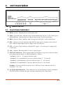
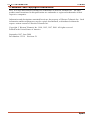
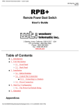
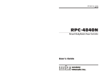
Figure 2.1: Instrument Front Panel
2.1. Front Panel Indicators
À PWR: (Power) Indicates power to the unit is ON.
Á TXD: (Transmit Data) Indicates data is being transmitted out pin 2 of the Control port
(MODEM Port). Indicates data is being received at pin 2 of the selected port.
 RXD: (Receive Data) Indicates data is being received at pin 3 of the Control port.
à RTS: (Request to Send) Indicates high RS232 signal at pin 4 (output) of the Control
port. Indicates high signal at pin 4 (input) of the selected port.
Ä CTS: (Clear to Send) Indicates a high RS232 signal received at pin 5 (input) of the
Control port.
Å ALL: Indicates Broadcast Mode is active, all ports open.
Æ SECTION Indicators: When optional Add-On Module(s) are present, indicators show
port connections on master or Add-On Modules as follows:
• Section 1: Ports 1 - 16 selected on master unit.
• Section 2: If second Module is present, indicates Ports 17 - 32 selected.
• Section 3: If third Module is present, indicates Ports 33 - 48 selected.
• Section 4: If fourth Module is present, indicates Ports 49 - 64 selected.
Example: If Section 4 LED and Active Port 2 LED are lit, this indicates port 50 is
selected (2 + 48 = 50).
Å ACTIVE PORT Indicators: These indicators are used with the previously mentioned
SECTION LEDs to indicate the port currently connected to the Control port.
2-1
CAS-161A Code Activated Switch, User's Guide
Unit Description
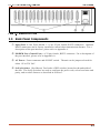
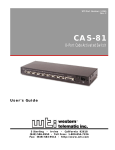
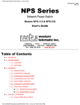
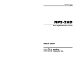
Figure 2.2: Instrument Back Panel
2.2. Back Panel Components
À Input Ports 1 - 16: Ports labeled 1 - 16 are 25-pin, female, RS232 connectors. Optional
RS422 connectors can be factory installed to increase data transmission distance. For a
description of the port interface, please refer to Appendix A.
Á MODEM Port (Control Port): A 25-pin, female, RS232 connector. For a description of
the port interface, please refer to Appendix A.
 AC Power: Power connector and ON/OFF switch. The unit can be jumper-selected for
either 115 or 230 VAC.
à SetUp Switches: (Not Shown) Two banks of DIP switches located on the underside of
the unit. The SetUp Switches are used to configure the prefix code, select baud rates and
parity, and set other features as described in Section 3.
2-2
3.
Installation
3.1. Configure SetUp Switches
There are two banks of DIP switches located on the bottom of the CAS-161A unit. These
switches are used to configure the Prefix Code (command character), enable the Broadcast
Mode, and select the baud rate. Switch functions are summarized on the bottom of the unit and
in the sections that follow:
Note: Switch positions “1” and “0” are indicated on the bottom of the unit.
3.1.1. SetUp Switch Bank 1
The bank of switches located closest to the rear panel are used to select the Prefix Code
Repetition Value, Broadcast Mode, and baud rate.
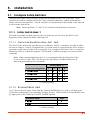
3.1.1.1. Prefix Code Repetition Value (Sw1 - Sw4)
The Prefix Code informs the unit that the next character will be a command. In order to allow
the unit to adapt to a variety of applications, it is often useful to require that the Prefix Code be
repeated several times in order to be recognized. For example if the Prefix Code is ^V and the
Repetition Value is 4, then the sequence “^V^V^V^V” would be sent prior to a port selection
command.
Note: When transmitting binary data, it is recommended that the Repetition Value
be set at four or eight. This will decrease the possibility of random characters in
data being misinterpreted as commands.
Switch (Bank 1)
Prefix Code Repetition
1
2
3
4
1 x Prefix Code *
1
0
0
0
2 x Prefix Code
0
1
0
0
4 x Prefix Code
0
0
1
0
8 x Prefix Code
0
0
0
1
* = Factory Setting
3.1.1.2. Broadcast Mode (Sw5)
On (1) forces all ports open. Data from the Control (MODEM) port is sent to all Input ports.
Useful for broadcasting to or controlling all Input devices. When enabled, concurrent data sent
by Input ports to the Control port will be jumbled together.
Broadcast Mode
Sw5
Disable*
0
Enable
1
* = Factory Setting
3-1
CAS-161A Code Activated Switch, User's Guide
Installation
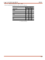
3.1.1.3. Baud Rate Select (Sw6 - Sw8)
Selects the operating baud rate; from 150 to 19.2K baud.
Switch (Bank 1)
Baud Rate
6
7
8
19200
0
0
0
9600*
1
0
0
4800
0
1
0
2400
1
1
0
1200
0
0
1
600
1
0
1
300
0
1
1
150
1
1
1
* = Factory Setting
3-2
CAS-161A Code Activated Switch, User's Guide
Installation
3.1.2. SetUp Switch Bank 2
The bank of DIP switches located closest to the front panel are used to select the Prefix Code
character and set the parity.
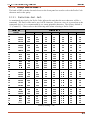
3.1.2.1. Prefix Code (Sw1 - Sw7)
As mentioned previously, the Prefix Code informs the unit that the next character will be a
command. The Prefix code can be any ASCII character. However, since it is passed on to the
connected device, it is recommended to use a non-printable character. The factory default is
^V (Control V). Please refer to the following table when selecting a Prefix Code.
Switch (Bank 2)
Prefix Code
(Name)
^@
^A
^B
^C
^D
^E
^F
^G
^H
^I
^J
^K
^L
^M
^N
^O
^P
^Q
^R
^S
^T
^U
^V
^W
^X
^Y
^Z
^[
^\
^]
^^
^_
1
2
3
4
5
6
7
(NUL)
ON
ON
ON
ON
ON
ON
ON
(SOH)
OFF
ON
ON
ON
ON
ON
ON
(STX)
ON
OFF
ON
ON
ON
ON
ON
(ETX)
OFF
OFF
ON
ON
ON
ON
ON
(EOT)
ON
ON
OFF
ON
ON
ON
ON
(ENQ)
OFF
ON
OFF
ON
ON
ON
ON
(ACK)
ON
OFF
OFF
ON
ON
ON
ON
(BEL)
OFF
OFF
OFF
ON
ON
ON
ON
(BS)
ON
ON
ON
OFF
ON
ON
ON
(UL)
OFF
ON
ON
OFF
ON
ON
ON
(LF)
ON
OFF
ON
OFF
ON
ON
ON
(VT)
OFF
OFF
ON
OFF
ON
ON
ON
(FF)
ON
ON
OFF
OFF
ON
ON
ON
(CR)
OFF
ON
OFF
OFF
ON
ON
ON
(SO)
ON
OFF
OFF
OFF
ON
ON
ON
(SI)
OFF
OFF
OFF
OFF
ON
ON
ON
(DLE)
ON
ON
ON
ON
OFF
ON
ON
(DC1)
OFF
ON
ON
ON
OFF
ON
ON
(DC2)
ON
OFF
ON
ON
OFF
ON
ON
(DC3)
OFF
OFF
ON
ON
OFF
ON
ON
(DC4)
ON
ON
OFF
ON
OFF
ON
ON
(NAK)
OFF
ON
OFF
ON
OFF
ON
ON
(SYN)
ON
OFF
OFF
ON
OFF
ON
ON
(ETB)
OFF
OFF
OFF
ON
OFF
ON
ON
(CAN)
ON
ON
ON
OFF
OFF
ON
ON
(EM)
OFF
ON
ON
OFF
OFF
ON
ON
(SUB)
ON
OFF
ON
OFF
OFF
ON
ON
(ESC)
OFF
OFF
ON
OFF
OFF
ON
ON
(FS)
ON
ON
OFF
OFF
OFF
ON
ON
(GS)
OFF
ON
OFF
OFF
OFF
ON
ON
(RS)
ON
OFF
OFF
OFF
OFF
ON
ON
OFF
OFF
OFF
OFF
OFF
ON
ON
(US)
Factory Setting = ^V
3-3
CAS-161A Code Activated Switch, User's Guide
Installation
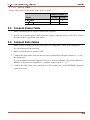
3.1.2.2. Parity (Sw8)
Parity can be set to Even, Mark, Odd, None, or Space.
Switch 8 (Bank 2)
Parity
1 (On)
X
Even, Mark
Odd, None, Space
0 (Off)
X
3.2. Connect Power Cable
1. Make certain the power switch is in the OFF position.
2. Attach one end of the power cable to the AC power connector on the CAS-161A. Attach
the other end to a grounded wall outlet.
3.3. Connect Data Cables
Note: Check to make certain all data cables are compatible. Refer to the Appendix
for a description of the interface.
1. Make certain the power switch is OFF.
2. Connect the data cables from the devices to be controlled to the ports labeled 1 - 16 on
the master unit.
If your installation includes optional CAS-161A Add-On Modules, install the additional
Modules as described in Appendix C, and then connect ports 17 - 64.
3. Connect the cable from your control device (PC, modem, etc.) to the MODEM connector
on the CAS-161A.
3-4
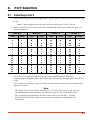
4.
Port Selection
4.1. Selecting a Port
1. After completing the installation procedure, flip the power switch on the back of the unit
to ON.
Note: Upon each power-up the unit will reset and all ports will be closed.
2. Refer to the Port Select Code Chart below and find the letter representing the port you
wish to connect to.
Module 1
Port
1
2
3
4
5
6
7
8
9
10
11
12
13
14
15
16
Module 2
Code
@
A
B
C
D
E
F
G
H
I
J
K
L
M
N
O
Port
17
18
19
20
21
22
23
24
25
26
27
28
29
30
31
32
Module 3
Code
P
Q
R
S
T
U
V
W
X
Y
Z
[
\
]
^
_
Port
33
34
35
36
37
38
39
40
41
42
43
44
45
46
47
48
Module 4
Code
a
b
c
d
e
f
g
h
i
j
k
l
m
n
o
Port
49
50
51
52
53
54
55
56
57
58
59
60
61
62
63
64
Code
p
q
r
s
t
u
v
w
x
y
z
{
:
}
~
DEL
3. Go to the PC or terminal connected to the Control (Modem) Port. Start your
communications program. Enter the Prefix Code followed by the appropriate Port Select
Code.
The Control port connects to the selected port and remains connected until another code
sequence is issued.
Note:
• The Prefix code is sent out the selected port. The Port Select code is not sent out
the selected port because all ports close briefly upon receipt of the Prefix code.
• The selected port opens during the Port Select code's stop bit time. All data
following the Port Select code is sent out the selected port including the next
Prefix code.
4-1
CAS-161A Code Activated Switch, User's Guide
Port Selection
Examples:
Assume the Prefix Code is ^V and the Prefix Code Repetition Value is 4. To connect to Port
14, use the following command:
^V^V^V^VM
Assume the Prefix Code is ^Y and the Prefix Code Repetition Value is 1. To connect to Port
44, use the following command:
^Yk
4.2. Closing/Opening All Ports
1. To close all ports at once, enter the Prefix code, followed by a space.
2. To open all ports at once, enter the Prefix code, followed by ^X (Control X) (CAN)
Example: Assume the Prefix Code is ^V and the Prefix Code Repetition Value is 2. To open
all ports at once, use the following command:
^V^V^X
4-2
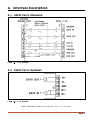
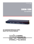
A. Interface Description
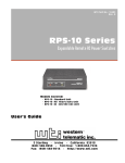
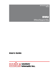
A.1. RS232 Ports (Standard)
Figure A.1: RS232 Interface
A.2. RS422 Ports (Optional)
Figure A.2: RS422 Interface
Note: Handshake signals are not passed. Pins 1 - 13 are open.
Apx-1
CAS-161A Code Activated Switch
Appendices
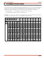
B. Printable Prefix Codes
Since the Prefix code is transmitted through the opened port, it is best to select a non-printable
Prefix Code. The procedure for selecting the Prefix Code is described in Section 3. If your
application requires a printable code, refer to the ASCII code chart below. Remember:
· Switch positions 1 - 7 correspond to ASC bits B1 - B7 on the chart.
· Switch positions should be ON for a 0 and OFF for a 1.
Example: To select the “@” character for a printable Prefix code: B1 - B7 on the chart shows 0
0 0 0 0 0 1 for “@”. Therefore, Sw1 - Sw6 should be ON and Sw7 OFF.
B7
B6
B5
¾¾¾¾¾¾¾¾¾¾¾¾¾¾¾¾¾®
¾¾¾¾¾¾¾¾¾¾¾¾¾¾¾¾¾®
¾¾¾¾¾¾¾¾¾¾¾¾¾¾¾¾¾®
Bits
®
b4
¯
b3
¯
b2
¯
b1
0
0
0
0
0
0
0
1
0
0
1
0
0
0
1
1
0
1
0
0
0
1
0
1
0
1
1
0
0
1
1
1
1
0
0
0
¯
1
0
0
1
1
0
1
0
1
0
1
1
1
1
0
0
1
1
0
1
1
1
1
0
1
1
1
1
Col
®
¯
Row
0
1
2
3
4
5
6
7
8
9
10
11
12
13
14
15
0
0
0
0
1
1
1
1
0
0
1
1
0
0
1
1
0
1
0
1
0
1
0
1
0
1
2
3
4
5
6
7
NUL
SOH
STX
ETX
EOT
ENQ
ACK
BEL
BS
HT
LF
VT
FF
CR
SO
SI
DLE
DC1
DC2
DC3
DC4
NAK
SYN
ETB
CAN
EM
SUB
EXC
FS
GS
RS
US
SP
!
#
$
%
&
¢
(
)
*
+
,
.
/
0
1
2
3
4
5
6
7
8
9
:
;
<
=
>
?
@
A
B
C
D
E
F
G
H
I
J
K
L
M
N
O
P
Q
R
S
T
U
V
W
X
Y
Z
[
\
]
^
_
`
a
b
c
d
e
f
g
h
i
j
k
l
m
n
o
p
q
r
s
t
u
v
w
x
y
z
{
|
}
~
DEL
Apx-2
CAS-161A Code Activated Switch
C.
Appendices
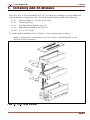
Installing Add-On Modules
The CAS-161A is field expandable to 32, 48, or 64 ports by attaching up to three additional
Add-On Modules to the master unit. Each Add-On Module Kit includes the following:
· 1 ea.
· 2 ea.
· 1 ea.
· 1 ea.
· 18 ea.
Add-On Module w/ six-wire power cable
Connecting Plates
Left Rack-Mount Bracket (Style-2)
Right Rack-Mount Bracket (Style-2)
6-32 x 3/8” Screws
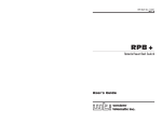
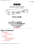
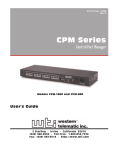
To install Add-On Modules, refer to Figure C.1 below and proceed as follows:
Note: If your unit has a stand-alone top cover, a Style-1 Rack-Mount Kit is also
required for the top Module.
Figure C.1: Add-On Module Installation
Apx-3
CAS-161A Code Activated Switch
Appendices
1. Remove the instrument top cover. If your unit has a stand-alone top cover, remove the
cover; the stand-alone cover is no longer required. If your unit has a Rack-Mount Kit,
remove the Rack-Mount Cover, Left and Right Rack-Mount Brackets (Style 1), and
screws. Save these parts, they will be used later.
2. Locate and unroll the ribbon cable (A) from inside the Master Unit. Hold the Add-On
Module (B) over the Master Unit (C). Feed the ribbon cable up through the bottom of the
Add-On Module. Plug the ribbon cable’s first connector into the Add-On Module’s P2
connector.
3. Plug the Add-On Module’s six-wire power cable at P1A (D) into the Master Unit’s P1B
(Power Out) receptacle. Set the Add-On Module in place. Locate the Sw3 DIP switch
inside the Add-On Module. Refer to the table below, and change switches to match the
Add-On Module.
Sw3
Add-On Module
Ports
1
2
3
4
Section 2
17 - 32
On
On
Off
Off
Section 3
33 - 48
On
Off
On
Off
Section 4
49 - 64
On
Off
Off
On
4. Repeat Step 3 to install any additional Add-On Modules (E and F). Refer to the table
above and make the appropriate DIP switch changes to match each Module/Section.
5. Install the Rack-Mount Top Cover (G) and Left and Right Style-1 Brackets (H) (removed
in Step 1) on the top Add-On Module. Attach only the two upper screws at this time.
6. Attach the Left and Right Style-2 Rack-Mount Brackets (I) to the remaining Modules
and/or Master Unit. Make sure the two threaded holes on each bracket face up. Secure
each bracket at the lower holes using the screws provided.
7. Place the Connecting Plates (J) over the Rack-Mount Brackets as shown in Figure 3.1.
The Connecting Plates must be installed with the plate flanges facing out, and with two
screw holes on the top edge and four screw holes on the bottom. Secure each Connecting
Plate with four screws. Repeat this step to secure any remaining Modules.
Apx-4
CAS-161A Code Activated Switch
Appendices
D. Specifications
Coding: ASCII, Asynchronous
Baud Rate: 300 to 19.2K baud, Switch Selectable
Interface: RS232, 25-pin connectors
Lines Switched: 2,3,4 and 5. Pins 6 and 8 of all Input ports follow Pin 6 of the Control port.
Power: 90 VAC to 130 VAC (jumper-selectable),
180 VAC to 260 VAC, 47 to 450 Hz.
Ambient Temp: 25°
Operating Temp: 0° C to 38°
Ventilation: 2" all sides
Size: 17.25" x 3.50" x 9.00" (W x H x D)
Weight: Master Unit: 7 lbs, Each Add-On Module: 4 lbs
Apx-5
CAS-161A Code Activated Switch
E.
Appendices
Customer Service
Customer Service hours are from 8:00 AM to 5:00 PM, PST, Monday through Friday. When
calling, please be prepared to give the name and make of the unit, its serial number and a
description of its symptoms. If the unit should need to be returned for factory repair it must be
accompanied by a Return Authorization number from Customer Service.
WTI Customer Service
5 Sterling
Irvine, California 92618
Phone: 949-586-9950
Toll Free: 1-800-854-7226
Fax: 949-583-9514
Email: [email protected]
Apx-6
CAS-161A Code Activated Switch
F.
Appendices
FCC Statement
WARNING: This equipment generates, uses and can radiate radio frequency energy and if not
installed and used in accordance with the instruction manual, may cause interference to radio
and television reception. It has been tested and found to comply with the limits for a Class A
computing device in accordance with specifications in Subpart J of Part 15 of FCC Rules,
which are designed to provide reasonable protection against such interference when operated in
a commercial environment. Operation of this equipment in a residential area may cause
interference, in which case the user at his/her own expense will be required to take whatever
measures may be required to correct the interference.
If this equipment does cause interference to radio or television reception, which can be
determined by turning the equipment off and on, the user is encouraged to try to correct the
interference by one or more of the following measures:
· Reorient the receiving antenna.
· Relocate the equipment with respect to the receiver.
· Move the equipment away from the receiver.
· Plug the equipment into a different outlet so that the equipment and receiver are on
different branch outlets.
· Ensure that the mounting screws, attachment connector screws and ground wires are tightly
secured.
· Ensure that good quality, shielded and grounded cables are used for data transmission.
You may find the following booklet prepared by the Federal Communications Commission
helpful:
How to Identify and Resolve Radio-TV Interference Problems
This booklet is available from the US Government Printing Office, Washington, DC 20402,
Stock No. 044-000-00345-4.
Apx-7
CAS-161A Code Activated Switch
Appendices
Trademark and Copyright Information
WTI, WTI logo and Western Telematic are trademarks of Western Telematic Inc. All other
product names mentioned in this publication are trademarks or registered trademarks of their
respective companies.
Information and descriptions contained herein are the property of Western Telematic Inc. Such
information and descriptions may not be copied, disseminated, or distributed without the
express written consent of Western Telematic Inc.
Copyright © Western Telematic Inc. 1990, 1992, 1997, 2000 All rights reserved.
Printed in the United States of America.
September 1997, June 2000
Part Number: 12114 Revision: D
Apx-8