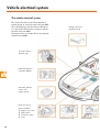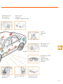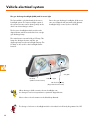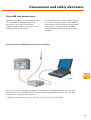
1
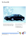
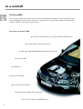
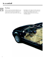
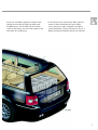
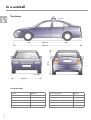
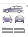
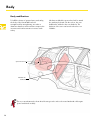
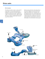
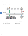
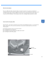
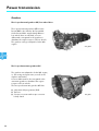
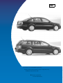
Service.
Self-Study Programme 261
The Passat W8
The Passat W8
S261_002
This Self-Study Programme presents the Passat
W8. We will only explain the design and function
where the items are totally new. All the changes
described refer to the Passat model year 2001.
The subject of the W8 engine is described in two
separate Self-Study Programmes:
●
●
Self-Study Programme No. 248
"The W Engine Concept“
Self-Study Programme No. 249
"The W8 Engine Management“
NEW
This Self-Study Programme explains the design
and function of new developments.
The contents of this book will not be updated.
2
Please always refer to the relevant Service literature for
up-to-date inspection, adjustment and repair instructions.
Caution
Important
At a glance
In a nutshell . . . . . . . . . . . . . . . . . . . . . . . . . . . . . . . . . . .4
Body . . . . . . . . . . . . . . . . . . . . . . . . . . . . . . . . . . . . . . . . 10
Occupant protection . . . . . . . . . . . . . . . . . . . . . . . . . . . 12
Drive units . . . . . . . . . . . . . . . . . . . . . . . . . . . . . . . . . . 15
Power transmission . . . . . . . . . . . . . . . . . . . . . . . . . . . .22
Running gear . . . . . . . . . . . . . . . . . . . . . . . . . . . . . . . . .24
Vehicle electrical system . . . . . . . . . . . . . . . . . . . . . . . 30
Convenience and safety electronics . . . . . . . . . . . . . .33
Heating and air conditioning system. . . . . . . . . . . . . .44
3
In a nutshell
The Passat W8
The top model of the Passat range is the first car from Volkswagen equipped with an 8-cylinder engine.
The Passat W8 offers luxury class refinement in performance, comfort, safety, quality and equipment.
It will be offered in saloon and estate versions.
Innovations in the Passat W8
●
●
●
●
●
●
Special crash and acoustic measures
W8 engine 4.0 l/202 kW (275 bhp) 4 valve per cylinder
Fuel tank 80 l
Climatronic
Bi-xenon headlights
●
Four-wheel drive 4 Motion
●
Exhaust system with 2 chrome tailpipes
●
4
6-speed manual gearbox or 5-speed automatic with Tiptronic
7.5 J17“ alloy wheels with 225R/45 tyres
This high-quality car is based on the Passat launched in model year 2001.
S261_003
The W8 engine is a totally new development.
One of the technical features is its compact size.
The engine power output is transferred to the
road via a 6-speed manual gearbox with
four-wheel drive (4Motion). Optionally there is a
five-speed automatic gearbox with Tiptronic
and 4Motion.
5
In a nutshell
The Estate
All the innovations in the Passat W8 saloon are
also in the estate. The bodies of both the estate
and the saloon have been strengthened to
improve the acoustics and increase crash safety.
6
But whether it is the estate or the saloon, the new
Passat W8 is recognisable from the outside by its
two chrome twin exhausts, the bi-xenon
headlights, additional chrome trims and the
17 inch alloy wheels.
Inside, the standard equipment includes head
airbags front and rear, high-class pillar and
headliner trims, chrome and real wood trims,
exclusive upholstery, an on-board computer and
automatic air conditioning.
In the extensive list of the Passat W8's optional
extras we have included new luxury leather
seats, new sports seats, a dynamic navigation
system with audio, TV unit and Internet access, a
digital sound pack and dark tinted rear windows.
S261_004
7
In a nutshell
The Saloon
100 kg
S261_073
S261_005
2703 mm
1461 mm
4703 mm
S261_006
S261_007
1746 mm
Size and weight
8
Length
4703 mm
Front track width
1511 mm
Width
1746 mm
Rear track width
1510 mm
Height
1461 mm
Perm. gross vehicle weight
2220 kg
Wheelbase
2703 mm
Kerb weight
1665 kg
Turning circle
11.5 m
Permitted roof load
100 kg
Tank capacity
80 l
Drag coefficient
0.27 cd
The Estate
100 kg
S261_073
S261_008
2703 mm
1497 mm
4682 mm
S261_009
S261_010
1746 mm
Size and weight
Length
4682 mm
Front track width
1515 mm
Width
1746 mm
Rear track width
1510 mm
Height
1497 mm
Perm. gross vehicle weight
2290 kg
Wheelbase
2703 mm
Kerb weight
1725 kg
Turning circle
11.5 m
Permitted roof load
100 kg
Tank capacity
80 l
Drag coefficient
0.27 cd
9
Body
Body modifications
To fulfill the claims of greater luxury and safety,
the body of the Passat W8 has been
strengthened. By strengthening, we make a
distinction between reinforcement to improve the
acoustics and reinforcement to increase crash
safety.
We have modified the spare wheel well to attach
the auxiliary fuel tank. On the saloon, the rear
bulkhead is welded to the rear backrest. The
backrest of the rear seat bench is therefore not
foldable.
Spare-wheel well
Welded rear
bulkhead
The cross strut between the front wheel housings is also enclosed on cars fitted with a V6 engine
(petrol and diesel models).
10
Acoustic measures:
Crash reinforcements:
A cross strut is bolted between the front wheel
housings. It is fixed to new supports welded to
the wheel housings. An additional strut is welded
to the front bulkhead near the front side member.
The front footwell is reinforced by an additional
cross-member.
Cross-member
Support for
cross strut
Cross strut
Reinforcement
S261_011
Body modifications
Crash reinforcements:
Acoustic measures
11
Occupant protection
Occupant protection
Occupant protection is ensured by the airbag
system with two front airbags, sidebags and
head airbags, belts and belt tensioners as well as
the child safety restraint system.
The Passat W8 has two full size front airbags on
the driver's and front passenger's sides. They
have a filling volume of 64 and 120 litres. The
central airbag control unit is located behind the
central console on the tunnel.
Head airbag
Side airbag
front passenger
Front airbag
driver
Front airbag
front passenger
Front airbag
module
front passenger
Front airbag
module
driver
Side airbag crash sensor
front passenger
The two side airbags are located in the front
seats and have a filling volume of 12 litres. The
head airbags each have a filling volume of 26
litres and are mounted in the vehicle headlining
above the doors.
12
Airbag control unit
Side airbag crash sensor
driver
The system has 2 lateral acceleration sensors
which are located below the front seats as on the
previous model.
The conventional inertia-reel seat belts are used
on the front and outer rear seats.
Ball-type tensioners are fitted to the front seats.
The rear seats are fitted with Wankel belt
tensioners.
The two types of belt tensioner are triggered by
mechanical/pyrotechnical capsules.
Head airbag
Head airbag
module
Three-point seat belt
Wankel belt tensioner
S261_012
Side airbag
module
Ball-type tensioner
Seat with integrated
side airbag
Side airbag
driver
The top part of the seat belts on the new Passat is flexible.
The bottom part is bolted rigidly to the brackets.
13
Occupant protection
Child safety restraint system
Both the integrated child safety seats and the Isofix system are available on the Passat W8.
Integrated child safety seats
To use the integrated child safety seat, the swab
elements must be raised and engaged. The
correct belt run is corrected by an additional
shoulder belt guide for children measuring 1.3 m
to 1.5 m tall. A belt guide hook on the raised
swab ensures that the belt runs safely across the
child's lap.
Belt guide hook
S261_013
The Isofix System
The new Passat W8 is fitted both with a standard
preparation for receiving the ISOFIX system
retaining eyes as well as integrated child safety
seats in the rear seats as an optional extra.
S261_014
14
Drive units
The W8 engine in general
The Passat W8 is fitted with one engine, the new
W engine generation, the W8. The W layout is
obtained by joining two V engines at an angle
of 72°. This layout achieves a very compact
8-cylinder engine with very small dimensions.
S261_015
S261_071
Compared with other 8-cylinder engines, the W8
is very lightweight due to the short size and
through the use of aluminium, slim conrods and
short pistons.
Four valves per cylinder, low-friction roller rocker
fingers, chain drive for the four overhead
camshafts with camshaft timing adjuster are
some of the noticeable features of this modern
engine.
S261_016
For more details, refer to Self-Study Programme No. 248.
15
Drive units
Specifications
Engine code
BDN
Displacement
3,999 cm3
Type
W engine
Valves per cylinder
4
Compression ratio
10.75±0.25:1
Bore
84.0 mm
Stroke
90.2 mm
Max. output
202 kW / 275 bhp
6000 rpm
Max. torque
370 Nm
2750 rpm
Engine management system
Motronic M7.11
Fuel
RON 98
(reduced output with RON 95)
Exhaust gas aftertreatment
Three-way catalytic converter
with Lambda control
Torque and power output
[kW]
[Nm]
500
200
400
150
300
100
200
50
100
2000
4000
6000 rpm
S261_017
Torque curve
Output curve
16
The power output of the W8 engine is 202 kW or
275 bhp at 6000 rpm.
Referred to the displacement, it has a power
output per litre of 50.5 kW or 68.7 bhp.
The 4.0 l W8 engine develops a maximum
torque of 370 Nm at an engine speed of
2750 rpm.
Referred to a displacement of 3999 cm3 this
results in a special maximum torque
of 92.5 Nm/l.
The fuel delivery system
The fuel delivery system of the Passat W8 has
tank capacity of 80 litres. It consists of a 60 litre
fuel tank as fitted to the Passat 2001 4Motion
and an additional tank containing 20 litres.
The two fuel tanks are connected by a connecting
tube. The additional fuel tank is located under
the spare-wheel well which is reduced in size for
this reason. If the car has a puncture, there is an
emergency wheel available in the reduced
spare-wheel well.
Additional fuel tank 20 l
Connecting tube
Fuel tank 60 l
S261_018
17
Drive units
The fuel pumps
The 60-litre fuel tank contains an electrical fuel
pump and a suction jet pump (entrainment
pump). There is another electrical fuel pump in
the 20-litre additional fuel tank. The different
heights of the main tank and the additional tank
require a controlled evacuation of the two tanks.
The engine is always supplied with fuel by the
pump in the 60 l tank.
When the tank is full, fuel is first pumped from
the 60 l tank. When the fuel level in the main
tank drops to 40 litres, the fuel pump in the
additional fuel tank cuts in and pumps fuel from
the additional tank to the main tank. When the
additional fuel tank is empty, the remaining fuel
is pumped from the main tank. The suction jet
pump (entrainment pump) delivers fuel from the
left chamber in the main tank to the fuel pump.
Fuel pump
Fuel pump
Suction jet pump
S261_019
Main fuel
tank 60 l
Additional fuel
tank 20 l
Connecting tube
18
Filler neck
S261_020
Fuel pump control
The fuel pump in the main fuel tank is controlled
by the engine control unit. The fuel pump in the
additional fuel tank is switched on by the fuel
pump control unit. For this reason there are four
fuel level senders in the entire tank and one
sender G293 with a Reed contact. The signals
from all the senders are sent to the fuel pump
control unit.
When the sender in the main fuel tank signals a
fuel level of 40 litres, the control unit switches the
pump in the additional fuel tank on. It pumps fuel
from the additional fuel tank to the main fuel
tank until the sender G293 signals "Additional
fuel tank empty“. Then the control unit switches
the pump in the additional fuel tank off. This
prevents the pump from running in an empty
tank as well as noise and additional power
consumption.
Fuel pump
and senders G292 and G293
Fuel pump
and sender G
S261_021
Fuel level indicator
sender G237
Suction jet pump
and sender G169
19
Drive units
Function diagram of fuel delivery system
G6
G 293
G 292
G
G 237
G 169
J 17
S228
Terminal 30
S
J 538
CAN convenience
G 23
S261_022
G 293 -Fuel level sender,
additional fuel tank empty
G 292 -fuel level sender,
G
J 17 - fuel pump relay
G23 - fuel pump
additional fuel tank
J538 - control unit for fuel pumps
- sender for fuel level indicator
S228- fuse in the fuse box
G 237 - sender 3 for fuel level indicator
G 169 - sender 2 for fuel level indicator
20
G 6 - fuel pump (pre-supply pump)
S
- fuse in the control unit
The fuel level indicator
Due to the different heights of the fuel tanks, four fuel level senders are required to calculate the
remaining fuel amount correctly. The signals from all the senders are evaluated in the fuel pump control
unit. The resulting signal runs via the CAN convenience bus to the dash panel insert and is used to
control the fuel level indicator. The fuel pump control unit is self-diagnosable by address word 58.
Control unit for fuel pump J538
The fuel pump control unit is located in the spare-wheel well embedded in plastic. It is connected to the
CAN convenience bus. The control unit is therefore connected to the dash panel insert. It has the
following tasks:
●
●
●
●
Evaluating signals from the four fuel level senders
Controlling the fuel level indicators
Controlling the fuel pump G 23 in the additional fuel tank
Controlling the tank warning lamp
Fuel pump
control unit J538
S261_023
21
Power transmission
Gearbox
The 6-speed manual gearbox 01E, four-wheel drive
The 6-speed manual gearbox 01E from the
Passat 2001 is also fitted to the Passat W8.
As the Passat W8 is supplied with 4Motion
four-wheel drive as standard, a Torsen
differential is integrated in the gearbox to
distribute the engine torque to all four wheels.
The gearbox casing is adapted to fit the W8
engine.
S261_024
The 5-speed automatic gearbox 01V
The gearbox was adapted to fit the W8 engine,
i.e. the casing and gear ratios, as well as the
clutches and brakes.
A Torsen differential is also integrated in the
automatic gearbox to distribute the engine
torque to all four wheels.
The five-speed automatic gearbox 01V has:
●
●
●
22
a dynamic shift programme (DSP)
Tiptronic
a torque converter with torque converter
lockup clutch
S261_025
The four-wheel drive 4Motion
The main function of the four-wheel drive is to
compensate the drive forces between the front
and rear axles as a factor of positive
engagement.
S261_026
The Torsen differential detects wheel slip in one
axle and distributes the drive power to the
wheels of an axle with better wheel grip.
The Torsen differential permits limited differences in
speed between the front and rear axles and
therefore allows ABS control processes. It operates
automatically and reacts independent of the driver.
The Torsen differential
(Torsen = torque sensing)
Rear axle drive
Differential casing
Front axle drive
Rear axle worm gear
Spur gears
S261_027
Front axle worm gear
Worm gears
23
Running gear
The four-link front suspension
The design of the front axle on the Passat W8 is identical to the Passat model year 2001. The following
components have been modified to cope with the higher weight and the resulting axle loads:
●
●
●
●
the wheel bearing housing
the wheel bearings
the wheel hub, and
the tubular subframe
Wheel bearing housing
Wheel hub
Tubular subframe
Wheel bearing
Steering
The steering remains unchanged compared with the Passat 2001:
●
●
24
steering column adjustable in height and reach
hydraulic power steering gear
S261_028
The double wishbone rear suspension
The proven double wishbone rear suspension
with closed tubular subframe is fitted to the
Passat W8.
What is new are the wheel bearing housings with
a modified attachment to the track rods.
Tubular subframe
Upper wishbone
Differential
Lower wishbone
S261_029
New wheel bearing housing:
●
●
●
Wheel bearing housing made of aluminium
Track rods guided at both ends
Larger track width
Aluminium
wheel bearing housing
Guided at both ends
S261_030
25
Running gear
The brake system
The Passat W8 currently has the most powerful
brake system of all Volkswagen car models.
Despite high engine performance, it achieves
excellent deceleration rates.
S261_031
261_031
Rear disc brake
Front disc brake
Hydraulic unit
and control unit
Front disc brake
Rear disc brake
Disc diameter x thickness
● 334 mm x 32 mm
● 321 mm x 30 mm
Disc diameter x thickness
● 269 mm x 22 mm
S261_032
26
S261_033
The hydraulic unit and ABS control unit
The Passat W8 receives the Bosch 5.7 ABS system with ESP (Electronic Stability Programme) and the
hydraulic brake assistant system (BAS). Special features of the Bosch 5.7 ABS system are:
●
●
●
The hydraulic unit and the control unit form a single unit
The ABS two-stage recirculating pump V39 replaces the hydraulic pump for
electronic dynamics control V156.
The pressure sensor G294 is contained in the hydraulic unit.
Control unit and rear of hydraulic unit
Pressure sensor
G294
S261_034
S261_035
27
Running gear
The ABS two-stage recirculating pump V39
is integrated in the Bosch 5.7 ABS system.
When the ESP intervenes, it supplies the required
preliminary pressure in the brake lines.
The pistons of the two-stage recirculating pump
operate at both sides.
While pressure is building up in working
chamber 1, the piston in working chamber
2 sucks brake fluid in. This creates a suction
process with every piston stroke.
Suction process in working chamber 2
Suction process in working chamber 1
Working chamber 2
Working
chamber 1
TDC
TDC
BDC
BDC
S261_040
S261_039
Suction line
Connecting line
A suction process takes place with every piston stroke.
S261_041
BDC
TDC
BDC
TDC
As the full suction volume is pumped almost
continuously, the maximum suction flow is much
smaller than on single-stage recirculating pumps.
This reduces the pressure in the suction line and
prevents cavitation.
It ensures rapid pressure build-up, even at
extremely low temperatures.
Cavitation is the formation of vapour bubbles in flowing liquids. The associated pressure surges
could cause material damage.
28
The hydraulic brake assistant system (BAS)
is integrated in the ABS control unit.
Accident research studies have shown that the
majority of drivers do not press hard enough on
the brakes in critical situations. This means that
pressure build-up is insufficient to reach
maximum vehicle deceleration.
Pressure sensor G294
S261_034
The pressure sensor G294 detects the pressure
rise in the brake system. The control unit
recognises
an emergency braking action by the rapid rise in
brake pressure within a specific period of time.
After it detects the emergency situation, it
increases the brake pressure within the ABS
control range. This shortens the stopping distance
and the car comes to a standstill faster.
Brake pressure [p]
Pressure rise in brake system
Time [t]
S261_043
ABS control range
Emergency braking
Normal braking
You will find explanations on the design and function of the hydraulic brake assistant system
(BAS) in Self-Study Programme No. 264.
29
Vehicle electrical system
The vehicle electrical system
The electrical system on the Passat W8 has a
similar design as on the Passat model year 2001.
The following pages will describe modifications
to components and functions compares with the
Passat model year 2001.
All components not described here are identical
with the Passat 2001.
Airbag control unit
(gearbox tunnel)
Connector station
A-pillar, right
Radio with dynamic
navigation RNS-D
Automatic gearbox
control unit
(right footwell)
Electronics box in
plenum chamber
●
Engine control unit
●
Relay station
●
Connector station
●
Fuses
Connector front end
30
Central electrics
Window lifter motor
with integrated
door control unit
Control unit for
parking aid
(luggage compartment, right)
TV tuner
CD changer
DSP
Window lifter motor
with integrated
door control unit
S261_044
Dash panel insert with
immobiliser
control unit and
diagnostic interface
(gateway)
Connector station
A-pillar, left
Fuse box, dash panel,
left
Convenience control
unit in footwell, left
31
Vehicle electrical system
The gas discharge headlight (GDH) with bi-xenon light
The Passat W8 is only fitted with the bi-xenon
headlight system. The improved light output of
the system increases active driving safety as the
driver can detect danger earlier.
Due to the gas discharge headlights, all bi-xenon
cars are equipped with automatic and dynamic
headlight range control (refer to SSP 251).
The bi-xenon headlight module produces the
dipped beam and the main beam from a single
gas discharge lamp.
The main beam is intensified by a H7 lamp. This
lamp also bridges the time until the gas
discharge lamp reaches its full light intensity. The
H7 lamp is also used for the headlight flasher
function.
S261_045
H7 lamp
(additional main beam)
Indicator lights
Gas discharge lamp
(dipped and main beams)
When driving in LHD countries, the two headlights can
be changed over from asymmetric to symmetric dipped beam.
Please refer to the information in the Workshop Manual.
The design of a bi-xenon headlight module is described in Self-Study Programme No. 251.
32
Convenience and safety electronics
Passat W8 with Internet access
Networking a vehicle is no longer limited to the
car's immediate surroundings but goes far
beyond this. The in-car communications
equipment now provides access to the worldwide data network, the Internet.
The Internet interface is a device which is linked
to the radio navigation system via the CAN bus.
Communication with the Internet (outside world)
is by means of a mobile radio aerial (GSM
antenna) which complies with the present-day
standard.
Internet interface with GSM antenna and connected laptop
S261_046
Internet access allows retrieval of specially processed driver-orientated information over the radio
navigation monitor, e.g. traffic information, trip/route planning, logistics support for hire cars and
breakdown or emergency call systems etc.
If a laptop is connected, the user can surf freely on the Internet and send e-mails.
33
Convenience and safety electronics
The convenience system
Interior monitor and anti-theft alarm system
The Passat W8 anti-theft alarm system is
equipped with a new function and a new alarm
horn. The new alarm horn, designated the H12, is
mounted in the plenum chamber. It has a
separate power supply.
Two lithium batteries integrated in the horn
ensure that the horn operates independent of the
car battery. The batteries have a life of approx. 5
to 7 years. If the batteries are discharged or
defective, the horn must be replaced.
Fitting location
Alarm horn H12
S261_047
Function
The horn communicates bidirectionally with the
convenience system control unit J393. After the
car is locked, the horn is armed via the control
unit. This means the vehicle power supply and
the horn signalling line are monitored in addition
to the other functions of the anti-theft alarm
system.
34
When the car is unlocked by the radio-wave
remote control key, the anti-theft alarm system is
deactivated. If the car is opened mechanically
via the lock cylinder of the door, the ignition must
be turned on within 15 seconds. If this does not
happen, the anti-theft alarm system is activated.
Function diagram of signal horn for anti-theft alarm system
J393
30a
H8
H12
F266
S261_048
F266
H8
H12
J393
30a
-contact switch for bonnet, in lock part
-signal horn for anti-theft alarm system
-alarm horn
-central control unit for convenience system
-positive terminal
The anti-theft alarm system has self-diagnostic capability. You will find the self-diagnosis in the vehicle
diagnostic testing and information system (VAS 5051) in the guided fault-finding under Body - Body
Repairs and the address word Convenience System. Please always use the latest version of the Workshop
Manual in the electronic Service Information System (ELSA) when fault-finding.
35
Convenience and safety electronics
The "Delta" radio system
supplements the current radio generation. At first glance the differences to the other units are its larger
size and a redesigned user interface.
Other new features compared to the current radio systems are:
●
●
●
●
●
●
integrated CD player
two FM/AM tuners
improved TIM function (Traffic Information Memory)
aerial sockets for aerial selection
compact connectors with central locking
CAN bus convenience networking
The important new button names and functions are summarised below.
The user interface
Audio CD entry
TIM function
There are two separate adjustable 2 hour timers to
program the time for starting to record radio traffic
information.
Example: The starting time for the trip to work and
back in the evening can be saved separately for 2
hours.
S261_049
36
MIX button
In CD mode, tracks are played in random sequence.
Rotary/push button for SCAN/TUNE
SCAN
Press in radio mode to search for a station or in CD
mode to briefly play the start of the track.
TUNE
Rotate to tune the FM/AM station manually or to
select the previous/next track in CD mode.
SEEK/TRACK button
SEEK
In radio mode, hit to start station search (SEEK) in AM
band. In FM or TP band, browse through storage
list.
TRACK
Hit briefly to skip forward or backward through CD
tracks. Press longer to start audible fast forward or
fast reverse of a track.
DSP button
Selects the menu for basic tone settings using
Digital Sound Processor (DSP)
37
Convenience and safety electronics
Radio rear panel
The rear panel of the radio contains the aerial sockets and the central connector.
The aerial sockets
Aerial input for FM/AM signal from control unit
for aerial selection
S261_050
Output to control unit for aerial selection
The aerial sockets
S261_051
To avoid plugging the aerial connectors in the
wrong socket the connector housings have a plug
coding and different colours. This means that a
connector will only fit in its associated aerial
socket. The connector engages when it is
plugged into the socket. To release the connector,
operate the unlocking mechanism on the socket.
Aerial wire
Plug coding
Central connector
lock
S261_052
Central connector with central
locking
The central modular connector groups all the
individual connectors, such as connectors for the
CD changer or loudspeakers. The individual
connectors can be plugged separately in the
central connector housing.
Locking and unlocking is by means of a central
locking mechanism.
Connector and locking
clip
S261_053
S261_054
38
Tuner
The radio has two integrated FM/AM tuners.
One of the tuners is only adjusted for receiving
frequencies from FM/AM stations. The other
tuner is used for setting the frequencies to
receive TP/FM traffic radio stations. This allows
selection of traffic radio messages from a TP
station irrespective of the FM station setting.
Example:
You are listening to an FM station, e.g. NDR 2,
which broadcasts supraregional traffic radio
messages. To receive current regional traffic
radio messages, select a TP station e.g.
ANTENNE by pressing the TP button. When the
selected TP station broadcasts traffic radio
messages, they will cut into the current
programme of the FM station the driver is
listening to. This also applies when the driver is
listening to an AM/MW station or the radio is in
CD mode.
FM station
TP station
If the "TP tuner“ is not being used to receive
TP stations, e.g. TP button OFF, it supports the
"FM tuner“. It checks the alternative frequencies
of an FM station setting to find a better reception
frequency.
S261_074
This makes checking the alternative frequencies
faster and avoids short-term mute pauses caused
by checking.
39
Convenience and safety electronics
CAN bus networking
To control functions and processes, the radio control unit and the dash panel insert exchange the
following information over the CAN bus.
●
NO contact
●
Terminal 15
●
Road speed signal (GALA)
●
Display lighting
●
Self-diagnosis processing
●
Radio convenience coding
●
Control signals from the multifunction steering wheel
●
Vehicle identification number
S261_055
For further Information on the subject of the radio system, refer to the following Self-Study
Programmes:
SSP 147 Radio Systems ´94
SSP 199 The Radio Navigation System
SSP 201 The Lupo
For more details on how to operate the radio system, please refer to the related operating
manual.
40
The radio aerial system
FM/AM reception of the radio system on the
Passat W8 has been considerably improved. This
was achieved by fitting four independent
FM/AM aerials (see SSP 147).
If reception is poor, the aerial control unit
switches to another aerial with a stronger signal.
The aerials are in different locations on the
saloon and on the estate.
Location of aerials on the saloon
On the saloon, the AM medium wave aerial is
above the rear window heater. The four FM
aerials are integrated in the rear window heater.
Suppressors in the supply wires of the rear
window heater prevent the radio signals received
from flowing via the positive and negative
terminals of the rear window heater.
Outside view onto the rear window in direction of travel
Amplifier 1
AM/FM
aerial
Amplifier 4
FM aerial
Amplifier 2
FM aerial
Amplifier 3
FM aerial
S261_056
41
Convenience and safety electronics
Location of aerials on the estate
On the estate, the aerials are located in the rear
side windows. Viewed in the direction of travel
there is a combined AM/FM aerial on the lefthand side and two FM aerials on the right-hand
side.
As on the saloon, each FM aerial is allocated to
an aerial amplifier. Even on the estate, the
amplifiers should not be wrongly allocated. As
the aerials on the estate do not use the rear
window heater, no suppressors are required.
Side window, left
Side window, right
S261_057
Amplifier 1
AM/FM aerial
Amplifier 2
FM aerial
Amplifier 3
FM aerial
Amplifier 4
FM aerial
The aerial amplifiers
Each FM aerial is allocated to an aerial amplifier.
They are precisely matched to their fitting
location and must not be allocated wrongly.
Depending on country-specific radio
frequencies, a number of antenna amplifier
variants can be fitted.
S261_058
42
Function
The radio signal received from one of the four
aerials runs via an aerial switch circuit inside the
aerial selector control unit to the tuner. In the
tuner, the signal quality is checked and the result
is fed back to the control unit via an aerial output
line.
If the selected signal is too weak for tuner
reception, the aerial switch switches
automatically to the next of the four aerials.
This process is repeated until an aerial is found
with good reception. Switchover is so fast that the
car occupants do not notice it.
Function diagram for aerial system (example: Passat estate)
Side window
Side window
right
left
AM/
FM 1
FM 3
FM 2
FM 4
Switch
Terminal 30
S261_059
Control unit J515
The control unit for aerial selection J 515
S261_060
Aerial inputs
Output to
tuner
is located under the rear shelf on the saloon or
on the rear left wheel housing in the luggage
compartment of the estate. Its function is to
switch over to the aerial with the best reception.
Input from
tuner
Power supply
This aerial system is currently offered with the "Delta" radio system.
43
Heating, air conditioning system
Heating and air conditioning system
The CLIMAtronic with fully automatic control is offered on the Passat W8.
A combination of the following components forms the main difference with the previous fully automatic
air conditioning system fitted to the Passat:
●
●
Sender for evaporator outlet temperature G263
Externally regulated compressor with regulating valve N280 and integrated overload protection,
The interaction between these two components in conjunction with the entire CLIMAtronic results in a
needs-orientated temperature control.
It permits a reduction in power consumption and helps to save fuel consumption.
Distribution box and housing for evaporator
S261_061
Evaporator
Front view
Sender for outlet
temperature G 263
S261_062
Rear view
44
The externally regulated compressor
The compressor basically works on the principle of the swash plate.
The technical features of the externally regulated compressor are:
●
●
●
●
●
One-sided swash plate compressor with 7 lifting pistons
Variable lifting volume to match the refrigerating capacity demand
Hollow pistons
Belt pulley drive with no magnetic clutch and integrated overload protection
External regulating valve N280 to regulate the pressure conditions in the compressor
Belt pulley with
integrated overload protection
Lifting pistons
Regulating valve
N 280
Shaped rubber
element
Driven plate
S261_063
Swash plate
Terminal for Climatronic
control unit J255
Function
The CLIMAtronic control unit J255 variably
controls the regulating valve on the compressor
N 280. Depending on the parameters, input
desired temperature, ambient and interior
temperature, evaporator temperature and
refrigerant pressure in refrigerant circuit, the
pressure conditions on the intake pressure side is
changed by a control voltage.
The inclined position of the swash plate changes.
This determines the stroke volume and therefore
the refrigeration performance generated.
The compressor continues to run via the ribbed
V-belt drive even when the air conditioning
system is off. The delivery volume of the
refrigerant is regulated to under 2%.
45
Heating, air conditioning system
The overload protection
The V-belt pulley and the driven plate are
positively joined by a shaped rubber element.
When the compressor is operational, the two
plates rotate in the same ratio to each other.
Compressor in function
Belt pulley
Shaped rubber element
Drive shaft
Compressor
Belt pulley
Driven plate
Shaped rubber
element
46
S261_064
If the compressor is damaged internally, it may
cause the drive shaft to block. The driven plate
will also stop.
This drastically increases the transfer forces
between the belt pulley and the driven plate. The
shaped rubber element is pressed by the belt
pulley in the direction of rotation onto the
blocked driven plate.
The projecting shapes on the rubber element
shear off and the joint between the belt pulley
and the driven plate is separated. The belt pulley
continues to rotate unhindered. This prevents any
damage to the ribbed V-belt and excludes
engine damage.
Compressor blocked
Distorted shape
on blocking
Belt pulley
Shaped rubber element
Sheared
material
blocked
Drive shaft
Compressor
Belt pulley
Blocked driven plate
Shaped rubber
element
Sheared material
S261_065
47
Heating, air conditioning system
The evaporator control circuit
When the CLIMAtronic is ON and the driver
enters the desired temperature, the refrigerant
demand is determined and changed by a
number of different influences.
The components described below form a control
circuit for regulating the desired temperature.
CLIMAtronic control unit J255
The compressor regulating valve N280
The external regulating valve forms an interface
between the suction and high pressure sides of
the compressor. It balances out the pressures
applied.
For example, if the cooling output is increased,
the regulating valve is controlled by the
CLIMAtronic control unit J255.
When the control voltage is applied to the
electromagnet control valve, a plunger in the
control valve moves. The period of the control
voltage applied determines the amount of travel.
The adjustment changes the cross-section of the
opening between the suction and the high
pressure sides in the valve. High pressure rises as
the suction pressure drops. This causes the piston
stroke to reposition the swash plate at a greater
angle.
Compressor regulating
valve N280
48
Outlet temperature sender G263
Influencing parameters:
The outlet temperature sender G263 is located in
the air duct behind the evaporator. It detects the
vent temperature downstream of the evaporator.
●
Input of desired temperature
●
Ambient temperature
●
Interior temperature
●
Temperatures downstream of evaporator and air outlets
●
Pressure level in refrigerant circuit
Intake air
If fulfills two important tasks:
●
it ensures that the air conditioning system is
switched off at 0°C downstream of the
evaporator.
●
together with the externally regulated
compressor, the outlet temperature
downstream of the evaporator can now be
regulated between 0°C and approx. 10°C.
Advantage:
It is no longer for the heat exchanger to "reheat"
cold air when the outlet temperatures are
between 0°C and 10°C.
This reduces power consumption and saves fuel.
Cooled air
Outlet temperature sender
S261_068
G263
49
Notes
50
Notes
51
261
For internal use only © VOLKSWAGEN AG, Wolfsburg
All rights reserved. Technical specifications subject to change without notice.
140.2810.80.20 Technical status: 08/01
❀ This paper is produced from
non-chlorine-bleached pulp.