1
SERVICE MANUAL
Table of Contents
CHAPTER 1: INTRODUCTION
1.1Introduction.........................................................................................1
1.2 Checklist and Contact Info..................................................................4
CHAPTER 2: NETWORK CONFIGURATION & SETUP
2.1
Getting Connected Guide - Wireless..................................................6
CHAPTER 3: CONSOLE CONFIGURATION & SETUP
3.1
3.2
3.3
3.4
3.5
Wifi Board Installation & Testing - 5x TM Console..............................10
Wifi Board Installation & Testing - 5x Universal Console....................13
Wifi Board Installation & Testing - 7xe TM Console............................16
Wifi Board Installation & Testing - 7xe Universal Console..................19
Required Software Versions...............................................................22
CHAPTER 4: ASSET MANAGEMENT WEBSITE SETUP
4.1
Setting up a new facility on the Asset Management website..............23
CHAPTER 5: TROUBLESHOOTING
5.1
ii
Troubleshooting - Asset Management Installations............................25
Introduction
1.1 INTRODUCTION
The Asset Management system is a feature available on all 5x, 7x, 7xe, and 7xi cardio designed to allow remote monitoring of cardio equipment.
This web-based feature provides users with the ability to log in from anywhere and check on the status of all the equipment. The site provides
information including serial numbers, time/distance totals, software versions, and a history of any error codes that the unit has shown.
Additionally, service guides, parts lists, and unit drawings for each unit are available through the Asset Management site.
1
Introduction
1.1 INTRODUCTION - CONTINUED
Asset Management will send email notifications for any error messages that occur on the equipment, notifying both Matrix Fitness customer
support and the facility.
To provide the best experience possible, Matrix Fitness Asset Management also allows for the user to create a service request ticket in the event
that there is a problem with a piece of equipment.
2
Introduction
1.1 INTRODUCTION - CONTINUED
Asset Management Product Workflow
Here is a list of the steps that must be completed for Asset Management.
1. Customer expresses a desire to have Asset Management in their facility.
2. Asset Management Qualifier document is provided by the sales team and completed by the customer prior to
the order being submitted.
3. Johnson Fitness Creates a Facility ID for the customer.
4. If Necessary, Johnson Fitness creates a user ID for the customer to access the Asset Management site.
5. A site survey is performed to determine how many Access Points are required to provide adequate wireless
coverage in the facility. Access points are ordered based on the result of this survey.
6. Access points are installed in the facility and connected to the facility’s internet line.
7. New equipment is installed.
8. Consoles are set up to support Asset Management and the Asset Management feature is turned on.
9. Customer can now view equipment online in the Asset Management website.
a. Note – A workout must be completed before the Equipment will report data to the website. It is
recommended that a brief workout is
performed directly after turning on Asset Management.
NOTE: Steps 6-8 can be performed in any order. The order provided is the most streamlined process. All 3 of
these steps can be performed at the time of install.
3
Introduction
1.2 CHECKLIST AND CONTACT INFO
Matrix Fitness Asset Management™ System - http://am.matrixfitness.com
The Matrix Fitness Asset Management™ System is a feature designed to allow remote monitoring of all Matrix Fitness 5x, 7x, 7xe, and 7xi
cardio equipment.
This web-based feature provides a facility owner with the ability to log in from any location and check on the status of equipment. The secure
site provides Matrix Fitness product information, including serial numbers, time / distance totals, software versions and a history of any error
codes that the unit has shown.
Asset Management will send email notifications for any error messages that the equipment shows, notifying both Matrix Fitness Customer
Technical Support and the facility.
To provide the best experience possible, Matrix Fitness Asset Management also allows the user to create a service request ticket in the event of
a problem with a piece of equipment.
In order to properly support the Asset Management System, the facility will need to provide:
____ A power source for the wireless access point(s).
____ An accessible Internet source near the workout area.
____ Contact information for the IT group within the facility or the facility's external IT source.
____ Permission for Matrix Fitness to install and configure the wireless access point(s).
OR
____ A release provided by Matrix Fitness and signed by the facility, confirming that they will support their own access point(s), with the
configuration files provided by Matrix Fitness.
Please fill in the form below as completely as possible and return to a Matrix Fitness Sales Representative.
Facility Name:________________________________________________
Facility Manager: _____________________________________________
Phone: _____________________________________________________
Email: ______________________________________________________
IT Contact for Facility __________________________________________
Phone: _____________________________________________________
Email: ______________________________________________________
____ Yes, this facility will use the Matrix Fitness supported wireless access point(s).
____ No, this facility will not use the Matrix Fitness supported wireless access point(s). Include the separate signed release (see next page)
with this document.
4
Introduction
1.2 CHECKLIST AND CONTACT INFO - CONTINUED
WAIVER AND RELEASE AGREEMENT
Johnson Health Tech North America, Inc. (hereafter, “Matrix Fitness”) has offered to supply a Matrix Fitness wireless access point ("Wireless
Access Point") to the Company identified below ("Customer") in conjunction with Customer's purchase of the Matrix Fitness Asset Management
product. The Wireless Access Point is built into the Asset Management product and would be installed in Customer's facility. Customer has
elected to purchase the Asset Management product without the Wireless Access Point. Customer's execution of this Waiver and Release
Agreement is a condition to Matrix Fitness's sale of the Asset Management product to Customer without the Wireless Access Point.
Customer acknowledges that it has been informed and understands that some of the reasons for using the Wireless Access Point provided by
Matrix Fitness are:
• The Wireless Access Point would be configured to interact with the Matrix Fitness cardio fitness equipment to provide information to Matrix
Fitness servers and Asset Management website;
• Installing the Wireless Access Point would allow Matrix Fitness to troubleshoot any connection issues that exist between the Matrix Fitness
equipment and the Wireless Access Point;
• Matrix Fitness would be able to monitor the status of the Wireless Access Point from its office to assist in troubleshooting; and
• Matrix Fitness would be able to track which cardio machines are online, and could gather data from these cardio machines, providing more
complete diagnostics in the event that equipment status updates are not appearing on the Asset Management website.
Customer acknowledges that there are known and unknown risks to using an access point different than the Wireless Access Point provided by
Matrix Fitness. By way of example, if Customer opts to use an access point different than the Wireless Access Point provided by Matrix Fitness:
• Matrix Fitness can no longer guarantee the full function of the Asset Management product;
• Matrix Fitness will ensure that the cardio equipment is correctly configured to connect with Customer’s access point;
• The Wifi Modules will be configured to communicate on 802.11 a/b/g/n band Networks for 7x and 7xe, and on 802.11b networks for 5x
equipment;
• Matrix Fitness will ensure that the equipment data that reaches its servers will be reported to the Asset Management website for Customer to
monitor its equipment using Asset Management;
• Matrix Fitness will NOT be able to provide troubleshooting or warranty service for issues that pertain to network maintenance, access point
failure, or connectivity issues through Customer’s own access point; and
• Matrix Fitness will NOT be able to provide additional troubleshooting or warranty service for access point configuration issues. Matrix Fitness
will provide Customer with the configuration settings that are on the equipment, and it will be the responsibility of Customer to set up its own
access point with the appropriate configuration.
In consideration for Matrix Fitness's willingness to sell the Asset Management product to Customer without the Wireless Access Point, Customer
agrees to all of the following. Customer states that it understands the information included in this Waiver and Release Agreement and has
chosen to use a different access point (an access point not supplied by Matrix Fitness) with full knowledge that it is assuming all known and
unknown risks in doing so. Customer acknowledges that it may sustain damages, losses, costs or expenses, both known and presently
unknown and unsuspected, arising out of or related to Customer's use of an access point other than the Wireless Access Point that could be
provided by Matrix Fitness and that such damages, losses, costs or expenses as may be sustained may give rise to additional damages,
losses, costs or expenses in the future. Customer further acknowledges that it has executed this Waiver and Release Agreement after taking
into account known and presently unknown and unsuspected, claims, damages, losses, costs and expenses. Customer, for itself and its
affiliated entities, predecessors, successors, assignors, assignees, insurers, officers, directors, owners, agents representatives and employees,
voluntarily and knowingly waives, and releases and discharges Johnson Health Tech North America, Inc. and its affiliated entities, predecessors
and successors and all of their respective officers, directors, shareholders, employees, agents, representatives, assigns, and insurers of and
from, all claims, actions, obligations and demands of any type arising out of or related in any way to Customer's use of an access point other
than the Wireless Access Point that could be provided by Matrix Fitness.
To the extent permitted by law, Customer voluntarily and with full knowledge of its significance, expressly waives and relinquishes any and
all rights it might have under any state or federal statute, rule or common law principle, in law or equity, relating to limitations on waivers and
releases of the type contained in this Waiver and Release Agreement.
Customer warrants and represents to Matrix Fitness that Customer’s execution of this Waiver and Release Agreement has been duly authorized
by all necessary corporate action of Customer and that the signature below is sufficient to bind, and does bind, Customer.
Company ("Customer") Name: ....................................................................................................
Name of Authorized Representative (Printed): ...........................................................................
Signature: ....................................................................................................................................
Date: ............................................................................................................................................
5
Network COnfiguration & setup
2.1 GETTING CONNECTED GUIDE - WIRELESS
OVERVIEW: There are 4 basic steps required to design a wireless network. They are:
1. Identifying areas that need coverage and estimating the number of APs needed.
a. Wireless coverage only needs to be provided in areas where cardio machines (equipment) need to have a wireless connection. If there
are spaces in the facility that don’t have cardio machines, there is no need to install access points in that area.
b. Once the areas needing coverage have been identified, calculate the minimum number of access points (APs) needed to support
the equipment. This number is only a starting point; additional access points will be required depending on the physical distribution of the
equipment and the RF challenges presented by the environment.
c. The next step in designing a network is to determine the distance from the AP that each piece of equipment will be placed. Equipment
cannot be placed further than 50 feet away from any given access point. This limitation is a best case scenario and only applies to equipment
that has direct line of sight to the access point. If there are walls, floors, lighting fixtures, windows, or other obstructions that block the line
of sight to the access point, the maximum distance the equipment can be from the access point is reduced significantly and will need to be
determined with empirical testing. For each group of equipment, stand in the center of the group and measure the distance to the furthest piece
of equipment. If this distance is greater than 50 feet, an additional AP is needed to cover this group of equipment. If equipment is installed on
different floors, additional APs should be used to cover the floors separately.
d. Ceiling height also affects wireless coverage. Do not mount APs to ceilings that are higher than 25’ or there will not be sufficient
coverage to the equipment. If the facility's ceilings are higher than 25’, consider mounting the AP on a nearby wall (illustrated later in this
document).
e. Understand and plan around interference. There are two main types of interference a facility needs to be concerned about.
- The first is physical interference. Physical objects that block line of sight to the access point will interfere with the signal. This includes
walls, windows, pillars, shelving, lighting, air ducting, etc. Try to pick mounting locations that allow for clear line of sight to the equipment. It
may be necessary to use a drop pole to lower the AP below these types of obstructions.
- The second type of interference is electrical and magnetic interference. This includes other wireless and radio frequency devices,
such as neighboring access points, cordless phones, baby monitors, and two-way radios. It also includes other devices that emit EMI
(electromagnetic interference), such as microwaves, high voltage power lines, electrical distribution boxes, fluorescent lighting ballasts,
generators, and any other electrical devices that turns currents on and off at high speeds. Avoid running network cable and mounting APs near
these sources of interference.
f. Once all of the above factors have been taken into consideration, the number of access points needed should be able to be identified, as
well as the locations that they should be mounted.
2. Once it is determined where the APs are going to be mounted, determine where the remaining network equipment will be housed. This
is often in a secure closet or communications room. Once this area is identified, plan out the cable runs. Each AP will need a “home run”
back to this closet. Network cables cannot be split or tapped; each run must connect only to a single AP. Measure the distance from the
communications closet to each access point mounting location. This distance cannot be longer than 90 meters (300’). If the distance exceeds
this limit, an IDF (intermediary distribution frame) will need to be installed which houses an additional network switch to act as a repeater for the
signal. Once all the runs are planned out, pull, terminate, and test all of the cable runs to the AP mounting locations.
3. Once cable has been pulled, the access points are ready to be mounted. The following section covers the propagation patterns of the APs
and the appropriate ways to mount them.
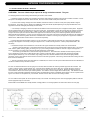
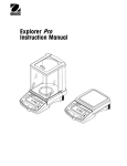
Both the MR12 and the MR24 have virtually identical coverage patterns. The coverage patterns are shown below and on the next page.
6
Network COnfiguration & setup
2.1 GETTING CONNECTED GUIDE - WIRELESS - CONTINUED
Both the 2.4GHz and 5 GHz patterns are fairly symmetric in the azimuthal plane (XY), so it makes little to no difference how the AP is rotated
about the Z-axis when mounting. The patterns are asymmetrical in the elevation plane (XZ), with significantly more antenna gain in the area
directly above the plane formed by the access point (Z+). This results in a coverage pattern that resembles an inverted cone whose axis of
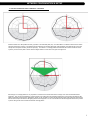
symmetry is normal to the plane of the AP. See the diagram below for a side view of the green coverage zone.
With this type of coverage pattern it is very important to mount the AP so that the base of the coverage cone covers the desired wireless
equipment. This can be accomplished by mounting the AP to the ceiling above the equipment with the face of the AP (the side with the LED
lights) pointed down toward the floor. Alternatively, the AP can be mounted on a wall at the approximate height of the equipment antennas with
the face of the AP (the side with the LED lights) pointed at the equipment. Do not mount the AP level with the equipment and the face pointed
up at the ceiling as this will not achieve the desired coverage pattern.
7
Network COnfiguration & setup
2.1 GETTING CONNECTED GUIDE - WIRELESS - CONTINUED
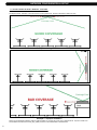
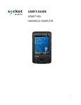
See diagrams below. Examples 1 and 2 show proper mounting placements. Example 3 illustrates a situation to avoid.
Example 1 - Ceiling Installation
Example 2 - Wall Installation
Example 3 - Improper Installation
Please see the Meraki MR installation guide for additional details on mounting the access point to different fixtures. http://docs.meraki.com/
download/attachments/8519767/meraki_setup_MR24.pdf?version=1&modificationDate=1349988446756.
8
Network COnfiguration & setup
2.1 GETTING CONNECTED GUIDE - WIRELESS - CONTINUED
4. After all the APs are up and running, perform a post installation coverage check. There are many tools that can be loaded onto a laptop
that will allow you to check RSSI (received signal strength intensity) values such as InSSIDer (available for free from Metageek). With this
program, or another program, installed on a laptop or smartphone, check the RSSI values around the fitness equipment. Values that are
greater than -70 dBm are required. If it is noticed that the signal strength is significantly lower than this value (-75 dBm or less), consider
installing additional access points.
9
Console Configuration & Setup
3.1 WIFI BOARD INSTALLATION & TESTING - 5x TM CONSOLE
NOTE: All consoles have a minimum software version for running Asset Management. Refer to the table in Section 3.5 for minimum
acceptable software versions for this console. The software versions in can be checked in Manager Mode. To enter Manager Mode press
and hold ELEVATION and SPEED DOWN at the same time for 3-5 seconds. Use the LEVEL keys to scroll to Manager Mode, and press ENTER.
Then use the LEVEL keys to toggle to Software and hit ENTER. This will display the current software versions. Use the LEVEL keys to toggle
through the versions to find the UCB software version. Press and hold the PAUSE key to exit.
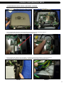
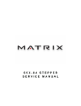
A WiFi board also needs to be installed and connected. There are two ways to verify if WiFi is connected on a 5x console. The first method is to
see if the WiFi module software appears in Manager Mode. If a WiFi module is connected WiFi software will appear (Figure A). The second way
to verify if WiFi is connected is to remove the back of the console by removing all the screws on the back (4 screws) and verify if the WiFi module
is plugged into the upper control board.
Figure A
Figure B
If it is determined that the console does not have a WiFi board installed, or if the WiFi board needs to be
replaced, follow the instructions below for installing the WiFi board and programming the T5x console for
Asset Management. NOTE: There are several different generations of T5x console. Even if the console
being worked on is slightly different than the pictures below, the process should be the same.
1. Remove the 6 screws holding the console to the handlebar (Figure C).
2. Disconnect the wire connections to the console and remove it (Figure D).
Figure C
10
Figure D
Console COnfiguration & setup
3.1 WIFI BOARD INSTALLATION & TESTING - 5x TM CONSOLE - CONTINUED
3. Remove the 4 screws holding the back of the console to the console and remove the cover (Figures E & F).
Figure E
Figure F
4. Mount the WiFi radio board to the console frame directly to the right of the main control board (Figure G).
5. Plug the WiFi radio board wire into the console and WiFi radio board (Figure H).
Figure G
Figure H
6. Mount the WiFi radio antenna to the console plastic. It should be mounted directly beneath the console frame (Figure I).
7. Plug the WiFi radio antenna into the WiFi radio board. Secure the WiFi radio antenna cord with tape (Figure J).
Figure I
Figure J
11
Console Configuration & Setup
3.1 WIFI BOARD INSTALLATION & TESTING - 5x TM CONSOLE - CONTINUED
8. Reverse Steps 1-2 to re-install the console to the treadmill.
9. Enter Engineering Mode by pressing and holding INCLINE DOWN and SPEED DOWN simultaneously for 3-5 seconds. Use the LEVEL
keys to toggle to Engineering Mode and push ENTER.
10. Use the LEVEL keys to toggle to AM System and press ENTER.
11. Select WiFi using the LEVEL keys to toggle and pressing ENTER to select. The console will beep twice to indicate WiFi is selected.
12. Press BACK and toggle to Manager Mode.
13. Enter Manager Mode and verify the WiFi software is 2.11 or higher in the Software Versions tab. Call Matrix Fitness CTS for the current
software if lower than 2.11.
14. To update the WiFi module software, plug the USB stick into the USB port on the front of the of the console and press 5, 0, 0, 1, ENTER.
The console will beep twice once the software has been updated.
15. Enter the Facility ID by entering Engineering Mode and selecting Facility ID. Enter the Facility ID. Enter the 0 number and every number
thereafter (for example if the Facility ID is 000110, enter 000110).
16. Verify the WiFi is setup by checking the IP address in Service 8. To find this information, enter Service Mode by pressing INCLINE DOWN
and SPEED DOWN simultaneously for 3-5 seconds until Manager Mode appears, then use the LEVEL keys to toggle to Service Mode and
press ENTER. Use the LEVEL keys to toggle to Service 8 and press ENTER. The Manufacture default IP address is 169.254.1.1, if WiFi has
been properly installed, the IP address will have changed from the default.
17. If the IP address has not changed from the default, reload the Config file by inserting the Flash Drive into the front USB port and pressing
5, 0, 0, 1, ENTER. The console should beep twice. Then recheck the IP address. Contact Matrix Fitness CTS for the Config File.
18. Hold STOP when finished to be returned to the main screen.
12
Console COnfiguration & setup
3.2 WIFI BOARD INSTALLATION & TESTING - 5x UNIVERSAL CONSOLE
NOTE: All consoles have a minimum software version for running Asset Management. Refer to the table in Section 3.5 for minimum
acceptable software versions for this console. The software versions can be checked in Manager Mode. To enter Manager Mode press and
hold LEVEL UP and DOWN keys at the same time for 3-5 seconds. Use the LEVEL keys to scroll to Manager Mode, and press ENTER. Then
use the LEVEL keys to toggle to Software and hit ENTER. This will display the current software versions. Use the LEVEL keys to toggle through
the versions to find the UCB software version. Press and hold the PAUSE key to exit.
A WiFi board also needs to be installed and connected. There are two ways to verify if WiFi is connected on a Universal 5x console. The first
method is to see if the WiFi module software appears in Manager Mode. If a WiFi module is connected WiFi software will appear (Figure A). The
second way to verify if WiFi is connected is to split the console by removing all the screws on the back (6 screws) and verify if the WiFi module is
plugged into the upper control board.
Figure A
Figure B
If it is determined that the console does not have a WiFi board installed, or if the WiFi board needs to be
replaced, follow the instructions below for installing the WiFi board and programming the Universal 5x
console for Asset Management. NOTE: There are several different generations of Universal 5x console.
Even if console is slightly different than the pictures below, the process should be the same.
1. Remove the 5 screws holding the console to the console mast (Figure C).
2. Disconnect the wire connections to the console (Figure D) and remove it.
Figure C
Figure D
13
Console Configuration & Setup
3.2 WIFI BOARD INSTALLATION & TESTING - 5x UNIVERSAL CONSOLE - CONTINUED
3. Remove the 6 screws holding the front of the console to the back and split the console (Figures E & F).
Figure E
Figure F
4. Mount the WiFi radio board to the console frame directly to the right of the main control board (Figure G).
5. Plug the WiFi radio board wire into the console and WiFi radio board (Figure H).
Figure G
Figure H
6. Mount the WiFi radio antenna to the console plastic (Figure I).
7. Plug the WiFi radio antenna into the WiFi radio board. Secure the WiFi radio antenna cord with tape (Figure J).
Figure I
14
Figure J
Console COnfiguration & setup
3.2 WIFI BOARD INSTALLATION & TESTING - 5x UNIVERSAL CONSOLE - CONTINUED
8. Reverse Steps 1-4 to re-install the console.
9. Enter Engineering Mode by pressing and holding the LEVEL UP and DOWN keys simultaneously for 3-5 seconds. Use the LEVEL keys to
toggle to Engineering Mode and push ENTER.
10. Use the LEVEL keys to toggle to AM System and press ENTER.
11. Select WiFi using the LEVEL keys to toggle and press ENTER to select. The console will beep twice to indicate WiFi is selected.
12. Press BACK and toggle to Manager Mode.
13. Enter Manager Mode and verify the WiFi software is 2.11 or higher in the Software Versions tab. Call Matrix Fitness CTS for the current
software if lower than 2.11.
14. To update the WiFi module software, plug the USB stick into the USB port on the front of the of the console and press 5, 0, 0, 1, ENTER.
The console will beep twice once the software has been updated.
15. Enter the Facility ID by entering Engineering Mode and selecting Facility ID. Enter the Facility ID. Enter the 0 number and every number
thereafter (for example if a Facility ID is 000110, enter 000110).
16. Verify the WiFi is setup by checking the IP address in Service 8. To find this information, enter Service Mode by pressing LEVEL UP and
DOWN simultaneously for 3-5 seconds until Manager Mode appears, then use the LEVEL keys to toggle to Service Mode and press ENTER.
Use the LEVEL keys to toggle to Service 8, then press ENTER. The Manufacture default IP address is 169.254.1.1, if WiFi has been properly
installed, the IP address will have changed from the default.
17. If the IP address has not changed from the default, reload the Config file by inserting the Flash Drive into the front USB port and pressing 5,
0, 0, 0, ENTER. The console should beep twice. Then recheck the IP address. Contact Matrix Fitness CTS for the Config File.
18. Hold STOP when finished to be returned to the main screen.
15
Console Configuration & Setup
3.3 WIFI BOARD INSTALLATION & TESTING - 7xe TM CONSOLE
NOTE: All consoles have a minimum software version for running Asset Management. Refer to the table in Section 3.5 for minimum
acceptable software versions for this console. To check a software version enter Manager Mode by pressing ENTER, 1, 0, 0, 1, ENTER.
Choose About, then Software Versions, this will display all the software versions on the console. Press the HOME key to return to the main
screen. If necessary contact Matrix Fitness Customer Support (CTS) and follow existing instructions for updating software.
There are three ways to verify if a WiFi module is installed on a T7xe console. The first is to look in the upper left corner of the main screen to
see if there is a wireless icon with the word connected (Figure A). If this icon is present, a WiFi Asset Management is connected. If the icon is
present, but the text reads Disconnected, follow step 3 below to check the connection of the WiFi module. The second and third methods for
checking if a WiFi module is connected only verifies if the module is installed and does not verify that WiFi Asset Management is fully setup and
configured for the facility. The setup instructions will still need to be followed.
The second method to verify if a WiFi module is installed is to push ENTER, then 4, 0, 0, 6, ENTER on the number keypad four times. A
windows screen will appear. Look at the bottom right corner to find an icon showing two computers. If the two computers do not have an "X"
(Figure B) WiFi is connected. If the two computers show an "X" through them (Figure C) WiFi is not connected. To exit hold the CHANNEL UP
and DOWN keys simultaneously for 3-5 seconds until the console power resets.
The third method for verifying if a WiFi module is installed is to remove the back of the console by removing the screws on the back cover (four
screws) and verify the WiFi module is plugged into the upper board (Figure D).
16
Figure A
Figure B
Figure C
Figure D
Console COnfiguration & setup
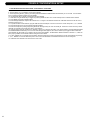
3.3 WIFI BOARD INSTALLATION & TESTING - 7xe TM CONSOLE - CONTINUED
If it is determined that the console does not have a WiFi board installed, or if the WiFi board needs to be
replaced, follow the instructions below for installing the WiFi board and programming the T7xe console for
Asset Management. NOTE: There are several different generations of T7xe console. Even if the console
being worked on is slightly different than the pictures below, the process should be the same.
1. Remove the 6 screws holding the console to the handlebar (Figure E).
2. Disconnect the wire connections to the console and remove it (Figure F).
Figure E
Figure F
3. Remove the 4 screws holding the back of the console to the console and remove the cover (Figures G & H).
Figure G
Figure H
4. Mount the WiFi radio board to the console frame directly to the right of the main control board (Figure I).
5. Plug the WiFi radio board wire into the console and WiFi radio board (Figure J).
Figure I
Figure J
17
Console Configuration & Setup
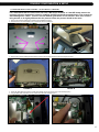
3.3 WIFI BOARD INSTALLATION & TESTING - 7xe TM CONSOLE - CONTINUED
6. Mount the WiFi radio antenna to the console plastic. It should be mounted directly beneath the console frame (Figure K).
7. Plug the WiFi radio antenna into the WiFi radio board. Secure the WiFi radio antenna cord with tape (Figure L).
Figure K
Figure L
8. Reverse Steps 1-2 to re-install the console to the unit.
9. Enter the Facility ID by entering Engineering Mode (press ENTER, 2, 0, 0, 1, ENTER on the lower keypad) and select Facility ID. Enter the
Facility ID as a six digit number (for example if a Facility ID is 110, enter 000110).
10. Make sure the C Safe mode is turned on by entering Manager Mode (press ENTER, 1, 0, 0, 1, ENTER on the lower keypad) and touch
CSafe Mode mode at the bottom of the screen. Then select On.
11. Press ENTER, 9, 0, 0, 1, ENTER to get to Networking Mode (Figure M).
12. Test the WiFi module by touching Netpulse Test, select Yes for NetPulse, then touch Test, and then touch Connect.
13. If the test fails, install the WiFi Config file by inserting the Flash Drive into the front USB port and touch IMPORT then retest. Contact Matrix
Fitness CTS if the Config File is needed. If test fails again, contact Matrix Fitness CTS.
14. When done, touch the HOME icon.
15 .Reset the console power by holding the CHANNEL UP and DOWN keys simultaneously for 3- 5 seconds.
16. Look for the WiFi symbol with the words Connected in the upper left hand corner of the home screen (Figure N).
Figure M
18
Figure N
Console COnfiguration & setup
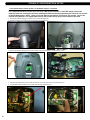
3.4 WIFI BOARD INSTALLATION & TESTING - 7xe UNIVERSAL CONSOLE
NOTE: All consoles have a minimum software version for running Asset Management. Refer to the table in Section 3.5 for minimum
acceptable software versions for this console. To check a software version enter Manager Mode by pressing ENTER, 1, 0, 0, 1, ENTER.
Choose About, then Software Versions, this will display all the software versions on the console. Press the HOME key to return to the main
screen. If necessary contact Matrix Fitness Customer Support (CTS) and follow existing instructions for updating software.
There are three ways to verify if a WiFi module is installed on a 7xe universal console. The first is to look in the upper left corner of the main
screen to see if there is a wireless icon with the word connected (Figure A). If this icon is present, WiFi Asset Management is connected. The
second and third methods for checking if a WiFi module is connected, only verifies if the module is installed and does not verify that WiFi Asset
Management is fully setup and configured for the facility. The setup instructions will still need to be followed.
The second method to verify if a WiFi module is installed is to push 4, 0, 0, 6, ENTER on the number keypad four times. A windows screen
will appear. Look at the bottom right corner to find an icon showing two computers. If the two computers do not have an "X" (Figure B) WiFi is
connected. If the two computers show an "X" through them (Figure C) WiFi is not connected. To exit hold the CHANNEL UP and DOWN keys
simultaneously for 3-5 seconds until the console power resets.
The third method for verifying if a WiFi module is installed is to remove the back of the console by removing the screws on the back cover (six
screws) and verify the WiFi module is plugged into the upper board (Figure D).
Figure A
Figure B
Figure C
Figure D
19
Console Configuration & Setup
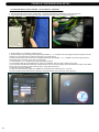
3.4 WIFI BOARD INSTALLATION & TESTING - 7xe UNIVERSAL CONSOLE - CONTINUED
If it is determined that the console does not have a WiFi board installed, or if the WiFi board needs to be
replaced, follow the instructions below for installing the WiFi board and programming the Universal 7xe console
for Asset Management. NOTE: There are several different generations of Universal 7xe console. Even if the
console being worked on is slightly different than the pictures below, the process should be the same.
1. Remove the 5 screws holding the console to the console mast (Figure E).
2. Disconnect the wire connections to the console (Figure F) and remove it.
Figure E
Figure F
3. Remove the 6 screws holding the front of the console to the back and split the console (Figures G & H).
Figure G
Figure H
4. Mount the WiFi radio board to the console frame directly to the right of the main control board (Figure I).
5. Plug the WiFi radio board wire into the console and WiFi radio board (Figure J).
Figure I
20
Figure J
Console COnfiguration & setup
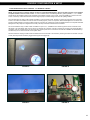
3.4 WIFI BOARD INSTALLATION & TESTING - 7xe UNIVERSAL CONSOLE - CONTINUED
6. Mount the WiFi radio antenna to the console plastic (Figure K).
7. Plug the WiFi radio antenna into the WiFi radio board. Secure the WiFi radio antenna cord with tape (Figure L).
Figure K
Figure L
8. Reverse Steps 1-2 to re-install the console to the unit.
9. Enter the Facility ID by entering Engineering Mode (press ENTER, 2, 0, 0, 1, ENTER on the lower keypad) and select Facility ID. Enter the
Facility ID as a six digit number (for example if a Facility ID is 110, enter 000110).
10. Make sure the C Safe mode is turned on by entering Manager Mode (press ENTER, 1, 0, 0, 1, ENTER on the lower keypad) and touch
CSafe Mode mode at the bottom of the screen. Then select On.
11. Press ENTER, 9, 0, 0, 1, ENTER to get to Networking Mode (Figure M).
12. Test the WiFi module by touching Netpulse Test, select Yes for NetPulse, then touch Test, and then touch Connect.
13. If the test fails, install the WiFi Config file by inserting the Flash Drive into the front USB port and touch IMPORT then retest. Contact Matrix
Fitness CTS if the Config File is needed. If test fails again, contact Matrix Fitness CTS.
14. When done, touch the HOME icon.
15 .Reset the console power by holding the CHANNEL UP and DOWN keys simultaneously for 3- 5 seconds.
16. Look for the WiFi symbol with the words Connected in the upper left hand corner of the home screen (Figure N).
Figure M
Figure N
21
Console Configuration & Setup
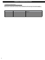
3.5 REQUIRED SOFTWARE VERSIONS
All consoles have a minimum software version for running Asset Management. Refer to the table below for minimum acceptable
software versions for each console. If the software version on the console is the one listed or higher, it will allow Asset Management.
MODEL
22
SN#s Associated with this Console
Required Minimum Software Version for Asset
Management
5x - 2012
CTM501, EP90, EP93, CS17, CS11
S005 or above
7xe - 2012
CTM503, EP92
L1.7 or above
5x - 2013
CTM519, EP611, EP612, CS18, CS19
S001 or above
7xe - 2013
CTM520, EP613
L1.7 or above
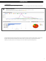
Asset Management Website Setup
4.1 SETTING UP A NEW FACILITY ON THE ASSET MANAGEMENT WEBSITE
Once Asset Management is officially part of the customer’s order and their contact information is verified, an organization will be created. This
will be generated by a qualified Johnson / Matrix Fitness supplier and sent via email to the main contact for that organization (or the registered
customer). If the customer does not have this information, please contact a Matrix Fitness CTS specialist (or a Matrix Fitness / Johnson supplier
in the region) for further assistance. Before creating a new organization, make certain the organization does not already exist on the Asset
Management website. If an organization cannot be located and a new one needs to be created, please follow the steps below.
•
Open an internet browser and go to http://am.matrixfitness.com
•
Log into the secure site with the credentials (username/password) that were provided.
•
In the upper right-hand corner of the page, will be CTS. Move a mouse over the word CTS and a drop down menu will appear below.
Select Add Organization to manually add an organization. Note: Before moving on to the next step, it is important to understand what
Organization means on the Asset Management website. Organization refers to an overarching, all encompassing umbrella for multiple
(related) facilities throughout various geographic locations. It does not refer to a specific facility. For example, gym chain ‘XYZ’ has hundreds
of sites around the world. This organization should be entered as ‘XYZ’ in the ‘Organization's Name’. If the organization is independent and
not affiliated, related, or operated by another facility, enter the unique facility’s name in the ‘Organization's Name’ field as it relates to that
specific location.
•
Enter the organization's name (based on the information above) and hit Save.
•
The website will load a page titled Organization in the upper left-hand corner under the Asset Management menu bar. Verify what page is
being looked at by looking at the address bar in the internet browser. At this point, it should read am.matrixfitness.com/organization. This
page will show the organization that was just created if the steps above were followed properly.
Once the Organization has been set up, a new Facility must be created.
Note: Steps 1 and 2 can be skipped if following these instructions in sequence.
•
Open an internet browser and go to http://am.matrixfitness.com.
•
Log into the secure site with the credentials (username/password) that were provided.
•
Select the organization to add a new facility under this organization. Note: Every facility must be added under an organization. If the facility
is independent and not affiliated, related, or operated by another facility, enter the SAME information for the Facility Name field that was
entered for the Organization's Name field.
•
At this point, the Dashboard page for the organization should be displayed. In the upper right-hand corner of this page, Organization
Management will be displayed. Move a mouse over the word and a drop down menu will appear below. Select Add Facility to manually
create a new facility under this organization.
•
Fill out the information on this new page for the specific facility being added under the organization.
•
Adding Tags to the facility specifies certain categories in which that facility associates itself with. Tags increase a facilities searchability and
helps users create custom lists according to their criteria. Note: Tags in Asset Management are used like keywords are used for search
engines (like Google). Tags are designated to each facility to differentiate one location from another.
•
Press Save when finished.
Credentials (username/password) will be sent to the primary (or registered) contact for the facility via email with a pre-assigned permission
level (Administrator, Standard, CTS, Technical, or Organization Manager). This will be generated by either a Matrix Fitness CTS specialist (for
customers in North America) or through the Matrix Fitness / Johnson supplier in that region (for customers outside of North America). Qualified
and approved users will have access to dynamic information about the equipment. The number of users allowed into the Asset Management
website should be limited to avoid any potential unwanted changes. To create a new user, follow the steps below:
•
Open an internet browser and go to http://am.matrixfitness.com.
•
Log into the secure site with the credentials (username/password) that were provided.
•
In the upper right-hand corner of the page, will be CTS. Move a mouse over the word and a drop down menu will appear below. Select
Users to manually add and create a new user. Or go to the User's List to see a list of users.
•
The website will update to a new page titled Users, which is represented by that text and an icon shaped like a person in the upper lefthand corner. Below ‘Users’ and the person icon, select + Add User to be transferred to the next page where the new user’s information
should be filled out.
•
At this point, the address bar in the web browser should read http://am.matrixfitness.com/user/add. Follow the format below to ensure
uniformity and minimize invalid logins by the new user:
Name
"First Name" (one space) "Last Name"
User name
"lastname.firstname" (no
Email
Input as it appears on the XXXXXXX
Password
"password" (no
capital letters)
Verification
"password" (no
capital letters)
capital letters)
23
Asset Management Website Setup
4.1 SETTING UP A NEW FACILITY ON THE ASSET MANAGEMENT WEBSITE - CONTINUED
After completing the above steps, follow these directions to complete creating the new user:
•
Select Enabled to active the new user’s credentials when this form is complete.
•
Select the appropriate role for this new user based on their permission level.
•
Under Organizations, a list of facilities will be displayed. Select one or multiple Organizations that the user is to have access to on the
Asset Management website. Note: To select multiple Organizations, hold ‘Ctrl’ on the keyboard and select another Organization. The
Organizations selected will be highlighted in blue.
•
Choose the appropriate Facilities from the drop down menu (holding ‘Ctrl’ for multiple selections).
•
Choose the appropriate Subscription Type from the drop down menu (holding ‘Ctrl’ for multiple selections).
•
Before hitting the Save button at the bottom left-hand corner of the page, it is recommended to select Notify so an email will be sent to the
new user when the Asset Management website accepts, acknowledges, and grants permission for the new user to access information on
the website.
•
After hitting the Save button and if the information on this form was filled out properly, an email will be sent to the new user and you will be
transferred back to the Users page where you will see User Created below the page title and icon (that is shaped like a person).
24
Troubleshooting
5.1 TROUBLESHOOTING ASSET MANAGEMENT INSTALLATIONS
Issue: The screen is completely blank on the treadmill:
Turn the power off at the base of the unit for 30 seconds, and turn back on. If the screen is still dark, press and hold the CHANNEL UP &
DOWN keys for 15-20 seconds, until the lower display on the console flashes. If screen remains dark, hold the CHANNEL UP & DOWN keys
again until the lower display flashes.
Issue: When trying to update software, the screen displays a red error message:
It is likely the console was trying to perform a different action when the software update was initiated. Reset the console power by holding the
CHANNEL UP and DOWN keys simultaneously for 3-5 seconds. Once the console is completely loaded (if the console has the Virtual Active
feature, the button will turn Maroon in color when it loads), insert the USB drive again. The green light on the USB will blink continuously while
the software updates.
Issue: When trying to update software, the flash drive does not load:
Remove the back of the console. Unplug the middle USB wire on the upper right hand corner of the upper control board (UCB). Remove the
USB wire from the VA board and insert it into the middle USB port on the upper right hand corner of the UCB. Reset the console power by
holding the CHANNEL UP and DOWN keys simultaneously for 3-5 seconds. When the console loads, wait until the VA button is maroon and
insert the Software USB Stick. Once the update is complete, return the wires to their original locations.
Issue: When trying to import the WiFi config files, screen says ‘import config failed':
Remove the back of the console. Unplug the middle USB wire on the upper right hand corner of the upper control board (UCB). Remove the
USB wire from the VA board and insert it into the middle USB port on the upper right hand corner of the UCB. Reset the console power by
holding the CHANNEL UP and DOWN keys simultaneously for 3-5 seconds. When the console loads, wait until the VA button is maroon and
insert the Software USB Stick. Once the update is complete, return the wires to their original locations.
Issue: The WiFi config has been imported, the access point is online, but the machine will not connect
when Netpulse test is performed:
Replace the Wifi connect wire, part 1000217073. Reset the console power by holding the CHANNEL UP and DOWN keys simultaneously for
3-5 seconds. Re-test. If this does not resolve, replace the Wifi board and Antenna. Reset the console power by holding the CHANNEL UP and
DOWN keys simultaneously for 3-5 seconds. Re-test.
For additional FAQs, check the Asset Management website for more information including videos on some common problems.
25
NOTES
NOTES
26
SERVICE MANUAL
Created & Maintained by Kevin Oeltjenbruns 3/7/13