1
EMC® VNX™ Series
Release 7.0
VNX™ System Operations
P/N 300-011-798
REV A01
EMC Corporation
Corporate Headquarters:
Hopkinton, MA 01748-9103
1-508-435-1000
www.EMC.com
2 of 114 Release 7.0
VNX™ System Operations
Contents
Introduction . . . . . . . . . . . . . . . . . . . . . . . . . . . . . . . . . . . . . . . . . . . . . . . . . .5
Limitations. . . . . . . . . . . . . . . . . . . . . . . . . . . . . . . . . . . . . . . . . . . . . . . .5
Considerations . . . . . . . . . . . . . . . . . . . . . . . . . . . . . . . . . . . . . . . . . . . .5
Cautions. . . . . . . . . . . . . . . . . . . . . . . . . . . . . . . . . . . . . . . . . . . . . . . . . .6
User interface choices . . . . . . . . . . . . . . . . . . . . . . . . . . . . . . . . . . . . . .6
Terminology . . . . . . . . . . . . . . . . . . . . . . . . . . . . . . . . . . . . . . . . . . . . . .6
Related information . . . . . . . . . . . . . . . . . . . . . . . . . . . . . . . . . . . . . . . .7
Managing the VNX . . . . . . . . . . . . . . . . . . . . . . . . . . . . . . . . . . . . . . . . . . . . .8
Power up the VNX . . . . . . . . . . . . . . . . . . . . . . . . . . . . . . . . . . . . . . . . . . . . .9
VNX VG2 and VG8 powerup. . . . . . . . . . . . . . . . . . . . . . . . . . . . . . . . .10
VNX5100 powerup. . . . . . . . . . . . . . . . . . . . . . . . . . . . . . . . . . . . . . . . .12
VNX5300 powerup . . . . . . . . . . . . . . . . . . . . . . . . . . . . . . . . . . . . . . . .14
VNX5500 powerup . . . . . . . . . . . . . . . . . . . . . . . . . . . . . . . . . . . . . . . .17
VNX5700 powerup. . . . . . . . . . . . . . . . . . . . . . . . . . . . . . . . . . . . . . . . .20
VNX7500 powerup. . . . . . . . . . . . . . . . . . . . . . . . . . . . . . . . . . . . . . . . .23
Power down the VNX . . . . . . . . . . . . . . . . . . . . . . . . . . . . . . . . . . . . . . . . . .26
VNX VG2 and VG8 planned powerdown . . . . . . . . . . . . . . . . . . . . . . .27
VNX5100 planned powerdown. . . . . . . . . . . . . . . . . . . . . . . . . . . . . . .31
VNX5300 planned powerdown. . . . . . . . . . . . . . . . . . . . . . . . . . . . . . .32
VNX5500 planned powerdown. . . . . . . . . . . . . . . . . . . . . . . . . . . . . . .35
VNX5700 planned powerdown. . . . . . . . . . . . . . . . . . . . . . . . . . . . . . .38
VNX7500 planned powerdown. . . . . . . . . . . . . . . . . . . . . . . . . . . . . . .41
Shut down the VNX in an emergency . . . . . . . . . . . . . . . . . . . . . . . . . . . .44
VNX series emergency shutdown . . . . . . . . . . . . . . . . . . . . . . . . . . . .44
Power up after an emergency shutdown. . . . . . . . . . . . . . . . . . . . . . . . . .45
Halt the Control Station. . . . . . . . . . . . . . . . . . . . . . . . . . . . . . . . . . . . . . . .46
Locally halt one Control Station . . . . . . . . . . . . . . . . . . . . . . . . . . . . .46
Locally halt two Control Stations . . . . . . . . . . . . . . . . . . . . . . . . . . . .46
Remotely halt one Control Station . . . . . . . . . . . . . . . . . . . . . . . . . . .47
Remotely halt two Control Stations . . . . . . . . . . . . . . . . . . . . . . . . . .47
Restart the Control Station . . . . . . . . . . . . . . . . . . . . . . . . . . . . . . . . . . . . .48
Locally restart one Control Station . . . . . . . . . . . . . . . . . . . . . . . . . . .48
Locally restart two Control Stations . . . . . . . . . . . . . . . . . . . . . . . . . .48
Remotely restart one Control Station . . . . . . . . . . . . . . . . . . . . . . . . .49
Remotely restart two Control Stations . . . . . . . . . . . . . . . . . . . . . . . .49
Halt the Data Movers . . . . . . . . . . . . . . . . . . . . . . . . . . . . . . . . . . . . . . . . . .51
Restart a Data Mover . . . . . . . . . . . . . . . . . . . . . . . . . . . . . . . . . . . . . . . . . .52
Check the system status. . . . . . . . . . . . . . . . . . . . . . . . . . . . . . . . . . . . . . .53
Back up the VNX database . . . . . . . . . . . . . . . . . . . . . . . . . . . . . . . . . . . . .55
Automatic VNX database backup . . . . . . . . . . . . . . . . . . . . . . . . . . . .55
Manual VNX database backup . . . . . . . . . . . . . . . . . . . . . . . . . . . . . . .56
Verify the daemons . . . . . . . . . . . . . . . . . . . . . . . . . . . . . . . . . . . . . . . . . . .58
View VNX daemons . . . . . . . . . . . . . . . . . . . . . . . . . . . . . . . . . . . . . . .58
View HTTPD daemons . . . . . . . . . . . . . . . . . . . . . . . . . . . . . . . . . . . . .58
Discover SCSI devices . . . . . . . . . . . . . . . . . . . . . . . . . . . . . . . . . . . . . . . .59
Save SCSI devices . . . . . . . . . . . . . . . . . . . . . . . . . . . . . . . . . . . . . . . . . . . .60
Identify the software versions . . . . . . . . . . . . . . . . . . . . . . . . . . . . . . . . . .61
Control Station command . . . . . . . . . . . . . . . . . . . . . . . . . . . . . . . . . .61
Data Mover or blade command . . . . . . . . . . . . . . . . . . . . . . . . . . . . . .61
Set the time zone of the VNX . . . . . . . . . . . . . . . . . . . . . . . . . . . . . . . . . . .62
Set Data Mover or blade time zone manually. . . . . . . . . . . . . . . . . . .62
VNX™ System Operations
Release 7.0
3 of 114
Change Control Station time zone using the CLI . . . . . . . . . . . . . . .62
Configure NTP service using the CLI. . . . . . . . . . . . . . . . . . . . . . . . . . . . .64
Set the date and time of the VNX . . . . . . . . . . . . . . . . . . . . . . . . . . . . . . . .66
Set Control Station date and time . . . . . . . . . . . . . . . . . . . . . . . . . . . .66
Set Data Mover or blade date and time. . . . . . . . . . . . . . . . . . . . . . . .66
Audit the VNX . . . . . . . . . . . . . . . . . . . . . . . . . . . . . . . . . . . . . . . . . . . . . . . .67
Configure IPv6 on the Control Station. . . . . . . . . . . . . . . . . . . . . . . . . . . .68
Configure IP aliasing . . . . . . . . . . . . . . . . . . . . . . . . . . . . . . . . . . . . . . . . . .69
Create an IP alias . . . . . . . . . . . . . . . . . . . . . . . . . . . . . . . . . . . . . . . . .69
Delete an IP alias. . . . . . . . . . . . . . . . . . . . . . . . . . . . . . . . . . . . . . . . . .69
Configure SNMP. . . . . . . . . . . . . . . . . . . . . . . . . . . . . . . . . . . . . . . . . . . . . .71
Change the ConnectHome settings . . . . . . . . . . . . . . . . . . . . . . . . . . . . . .72
Set the country code on the MT5634ZBA modem . . . . . . . . . . . . . . . . . .75
Manual instructions for setting the country code . . . . . . . . . . . . . . . . . .78
Change the Control Station hostname . . . . . . . . . . . . . . . . . . . . . . . . . . .82
Install Control Station Linux security alerts . . . . . . . . . . . . . . . . . . . . . . .85
New software release installations . . . . . . . . . . . . . . . . . . . . . . . . . . .85
Avoid private LAN IP address conflicts. . . . . . . . . . . . . . . . . . . . . . . . . . .86
Change VNX for block SP management port IP addresses . . . . . . . . . . .87
Interpret log files . . . . . . . . . . . . . . . . . . . . . . . . . . . . . . . . . . . . . . . . . . . . .88
Read log messages . . . . . . . . . . . . . . . . . . . . . . . . . . . . . . . . . . . . . . .89
NAS or SAN environment rules . . . . . . . . . . . . . . . . . . . . . . . . . . . . . . . . .94
Collect problem information . . . . . . . . . . . . . . . . . . . . . . . . . . . . . . . . . . . .97
Automatically collect and transfer logs . . . . . . . . . . . . . . . . . . . . . . .97
Configuration file . . . . . . . . . . . . . . . . . . . . . . . . . . . . . . . . . . . . . . . . .98
Run log collection and automatic transfer . . . . . . . . . . . . . . . . . . . . .99
Run log collection from the CLI. . . . . . . . . . . . . . . . . . . . . . . . . . . . . .99
Disable Automatic Collection and Transfer tool . . . . . . . . . . . . . . .101
Use CLI options to perform script operations . . . . . . . . . . . . . . . . .102
Troubleshooting. . . . . . . . . . . . . . . . . . . . . . . . . . . . . . . . . . . . . . . . . . . . .104
Where to get help . . . . . . . . . . . . . . . . . . . . . . . . . . . . . . . . . . . . . . . .104
E-Lab Interoperability Navigator . . . . . . . . . . . . . . . . . . . . . . . . . . . .104
Error messages for system operations . . . . . . . . . . . . . . . . . . . . . .104
Error messages for Data Mover. . . . . . . . . . . . . . . . . . . . . . . . . . . . .105
Recovery after an VNX SP failure . . . . . . . . . . . . . . . . . . . . . . . . . . .106
System activity output . . . . . . . . . . . . . . . . . . . . . . . . . . . . . . . . . . . .108
EMC Training and Professional Services . . . . . . . . . . . . . . . . . . . . .109
Index . . . . . . . . . . . . . . . . . . . . . . . . . . . . . . . . . . . . . . . . . . . . . . . . . . . . . .111
4 of 114
Release 7.0
VNX™ System Operations
Introduction
System operations are common operation tasks that include powering up or
powering down a server, halting or restarting a Control Station, a Data Mover, or
blade, or setting the server time, date, and time zone.
This document is part of the EMC® VNX™ Series documentation set and is
intended for use by system administrators responsible for performing day-to-day
operations of a VNX for file and for monitoring the server or resolving simple
operation problems.
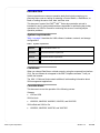
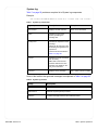
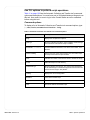
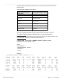
System requirements
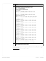
Table 1 on page 5 describes the VNX software, hardware, network, and storage
configurations.
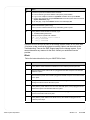
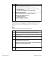
Table 1
System requirements
Software
EMC VNX Series version 7.0.
Hardware
No specific hardware requirements.
Network
No specific network requirements.
Storage
No specific storage requirements.
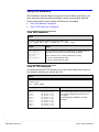
Limitations
When you change Data Mover or blade names by using the command line interface
(CLI), the new names do not appear in the EMC Unisphere software™ until you
refresh the browser.
The VNX 1.0 Release Notes contain additional, late-breaking information about
VNX management applications.
Considerations
This document covers the operation of the following servers:
Gateway:
◆
VG2 and VG8
VNX for block:
◆
VNX5100, VNX5300, VNX5500, VNX5700, and VNX7500
VNX unified and VNX for file:
◆
VNX™ System Operations
VNX5300, VNX5500, VNX5700, and VNX7500
Release 7.0
5 of 114
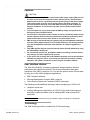
Cautions
!
!
CAUTION
◆
The power sockets at the rear of each uninterruptible power supply (UPS) provide
the blade enclosures, the automatic transfer switches (ATSs), and the Control
Stations with power for a predetermined time period during an AC power outage.
This backup power gives the server enough time to shut down gracefully. To
prevent premature discharge of the UPS batteries during a power outage and
improper shutdown, do not connect any other devices (power loads) to these
sockets.
◆
To prevent data loss, never power down the VNX by simply turning off the red
Emergency Power Off (EPO) switch.
◆
To avoid service disruption to other clients, do not turn off the two cabinet circuitbreaker switches when the cabinet contains other equipment powered by these
switches that either services other clients or is not part of the server.
◆
EMC strongly recommends that you regularly copy the VNX database backup file
from the Control Station and save it to a remote location for safe keeping. Always
copy the VNX database backup file when hardware or software upgrades are
planned.
◆
Only EMC qualified support personnel should restore the VNX database by using
the VNX database backup file.
◆
Do not manually edit the nas_db database without consulting Customer Service.
Any changes you make might disrupt services.
◆
If you use the CLI to change the Control Station hostname and use the Unisphere
software to manage the server, ensure that you follow this procedure carefully.
Otherwise, file systems cannot be created using the Unisphere software.
User interface choices
The VNX offers flexibility in managing networked storage based on interface
preferences and support environment. This document describes the system
operations of the VNX by using the CLI. You can also perform some of these tasks
by using one of the VNX management applications:
◆
EMC Unisphere software
◆
Microsoft Management Console (MMC) snap-ins
◆
Active Directory Users and Computers (ADUC) extensions
The following provide additional information about managing your VNX for file:
◆
Unisphere online help
◆
Installing Management Applications on VNX for File includes instructions on
launching Unisphere software, and on installing MMC snap-ins and ADUC
extensions.
Note: Unless otherwise directed, log in as nasadmin when executing CLI commands.
Terminology
The VNX Glossary provides a complete list of VNX terminology.
6 of 114 Release 7.0
VNX™ System Operations
Related information
Specific information related to the features and functionality described in this
document is included in:
◆
EMC VNX Command Line Interface Reference for File
◆
Parameters Guide for VNX for File
◆
Online VNX for File man pages
EMC VNX Documentation on the EMC Online Support website
The complete set of EMC VNX series customer publications is available on the
EMC Online Support website. To search for technical documentation, go to
http://Support.EMC.com. After logging in to the website, click the VNX Support by
Product page to locate information for the specific feature required.
VNX wizards
Unisphere software provides wizards for performing setup and configuration tasks.
The Unisphere online help provides more details on the wizards.
VNX™ System Operations
Release 7.0
7 of 114
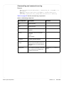
Managing the VNX
The tasks to manage the VNX are:
8 of 114 Release 7.0
◆
"Power up the VNX" on page 9
◆
"Power down the VNX" on page 26
◆
"Shut down the VNX in an emergency" on page 44
◆
"Power up after an emergency shutdown" on page 45
◆
"Halt the Control Station" on page 46
◆
"Restart the Control Station" on page 48
◆
"Halt the Data Movers" on page 51
◆
"Restart a Data Mover" on page 52
◆
"Check the system status" on page 53
◆
"Back up the VNX database" on page 55
◆
"Verify the daemons" on page 58
◆
"Discover SCSI devices" on page 59
◆
"Save SCSI devices" on page 60
◆
"Identify the software versions" on page 61
◆
"Set the time zone of the VNX" on page 62
◆
"Configure NTP service using the CLI" on page 64
◆
"Set the date and time of the VNX" on page 66
◆
"Audit the VNX" on page 67
◆
"Configure IP aliasing" on page 69
◆
"Configure SNMP" on page 71
◆
"Change the ConnectHome settings" on page 72
◆
"Set the country code on the MT5634ZBA modem" on page 75
◆
"Manual instructions for setting the country code" on page 78
◆
"Change the Control Station hostname" on page 82
◆
"Install Control Station Linux security alerts" on page 85
◆
"Avoid private LAN IP address conflicts" on page 86
◆
"Change VNX for block SP management port IP addresses" on page 87
◆
"Interpret log files" on page 88
◆
"NAS or SAN environment rules" on page 94
◆
"Collect problem information" on page 97
◆
"Troubleshooting" on page 104
VNX™ System Operations
Power up the VNX
The tasks to power up the VNX after a planned power down or after an emergency
shutdown are:
VNX™ System Operations
◆
"VNX VG2 and VG8 powerup" on page 10
◆
"VNX5100 powerup" on page 12
◆
"VNX5300 powerup" on page 14
◆
"VNX5500 powerup" on page 17
◆
"VNX5700 powerup" on page 20
◆
"VNX7500 powerup" on page 23
Release 7.0
9 of 114
VNX VG2 and VG8 powerup
The VG2 can be configured with either one or two blades and one or two Control
Stations. The VG8 has either two to eight blades and one or two Control Stations.
These instructions cover all configurations.
Step
Action
1.
If the VG2/VG8 is in a cabinet by itself (that is, the storage array is not in the same
cabinet), then turn off the cabinet circuit-breakers to remove all power from the VG2/VG8
cabinet.
2.
Verify that the VG2/VG8 blade enclosure power cables are disconnected from the cabinet
Power Distribution Panel (PDP). You will connect these power cables later.
3.
Verify that each Control Station power cable is disconnected from the PDP. You will
connect this power cable later.
4.
Turn on (I position) the left and right cabinet circuit-breaker switches at the back of the
cabinet near the bottom.
If the server is installed in a cabinet not manufactured by EMC, the circuit-breaker
switches might be in a different location.
5.
If the boot storage array is off, power it up. Follow the instructions in the array
documentation.
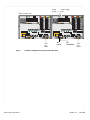
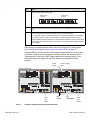
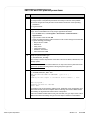
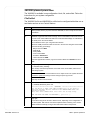
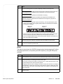
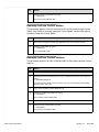
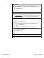
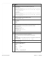
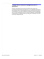
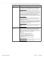
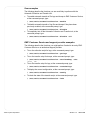
6.
Connect the blade power cables to the PDP and wait for the blades to power up. Look for
a blue power LED on the front of the blade enclosure to indicate that they are powered up.
Your system might contain a greater or a fewer number of blade enclosures. Connect the
blade power cables present.
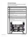
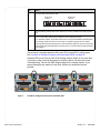
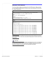
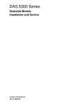
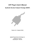
As an example, a VG8 with two Control Stations and two blade enclosures (0 and 1) is
shown below. The blade power cables are labeled 3, 4, 5, and 6.
Power distribution
panel (PDP)
Power distribution
panel (PDP)
2
CS 1
1
CS 0
6
2
3
3
2
1
2
2
1
0
#
3
2
2
1
2
0
10 of 114 Release 7.0
1
SP A
0
0
#
4
1
2
0
1
3
SP A
#
3
5
0
0
1
1
0
#
VNX™ System Operations
Step
Action
7.
Connect the power cables for the Control Station(s) to the PDP. In the example illustration
provided in step 6, these are power cables 1 and 2.
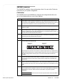
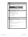
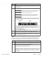
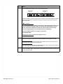
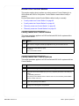
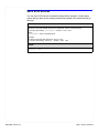
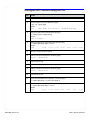
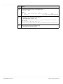
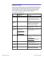
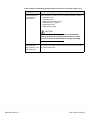
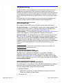
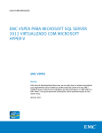
8.
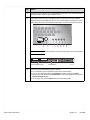
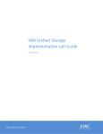
If the system power LED (D in the following figure) on the front of the Control Station
indicates that the Control Station is off, turn on the Control Station by pressing the Power
button (B) on the front. Ensure that the Control Station is powered up before continuing.
A
B
C
D
E
F
G
Note: The front bezel must be removed to access the Power button of the Control Station.
Control Station (front)
9.
Power button
CNS-000876
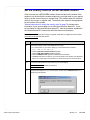
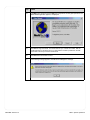
Check the system and hardware status as follows:
a. From a browser, type the IP address of the primary Control Station.
b. Log in to the Unisphere software as sysadmin and define the scope as Global.
c. Use the drop-down list at the topleft Dashboard to select the system name and view its
System Information page.
d. On this page, verify that the Status fields for the VNX display OK.
VNX™ System Operations
Release 7.0
11 of 114
VNX5100 powerup
The VNX5100 is the only available configuration: block.
Block
Follow the instructions below for your VNX5100 for block:
Step
Action
1.
Verify that the master switch/circuit breakers for each cabinet power strip are OFF.
2.
Ensure that the power cable for SP A is plugged into the SPS and power cord retention
bails are in place.
3.
Ensure that the power cord for SP B is plugged into the nearest power distribution unit
(PDU) on a different circuit from SPS A and that power cord retention bails are in place. In
a system with two SPSs, plug SP B into SPS B.
4.
Verify that the serial connection between management module A and the SPS is in place.
In a system with two SPSs, each management module has a serial connection to the
corresponding SPS.
5.
Verify that the power cables for the SPSs and any DAEs are plugged into the cabinet’s
power strips.
6.
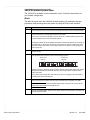
Turn the SPS power switches ON..
SPS power
switch B
SPS power
switch A
CIP-001115
7.
Ensure that any other devices in the cabinet are correctly installed and ready for power
up.
8.
Turn on the master switch/circuit breakers for each cabinet power strip.
In a 40U EMC cabinet, the master switches are on the power distribution panels (PDPs).
The storage system can take 10-12 minutes to complete a typical power up. Amber
warning LEDs flash during the power on self-test (POST) and then go off. The front fault
LED and the SPS recharge LEDs commonly stay on for several minutes while the SPSs
are charging.
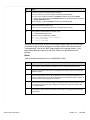
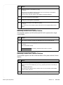
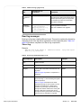
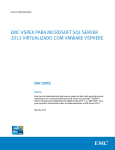
The powerup is complete when the SP power LED on each SP is steady green.
See "Location of Storage Processor power and status LEDs" on page 13.
If amber LEDs on the front or back of the storage system remain on for more than
10 minutes, make sure that the system is correctly cabled, and then refer to the
Troubleshooting Trees on the EMC Support page for the storage system. If you
cannot determine any reasons for the fault, contact your authorized service
provider.
12 of 114 Release 7.0
VNX™ System Operations
Power
supply
Power supply
fault
8Gb 6Gb
fibre SAS
2
3
4
3
3
3
2
2
2
1
1
1
0
0
8Gb 6Gb
fibre SAS
1 X4
5
2
3
4
5
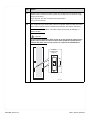
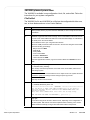
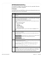
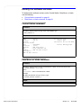
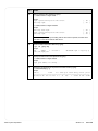
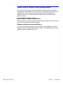
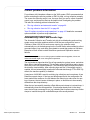
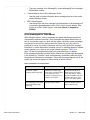
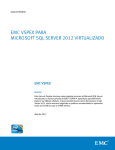
Figure 1
VNX™ System Operations
A
1 X4
6Gb SAS
0 X4
SAS
port
status
0
3
2
0
B
1
Disk processor rear
6Gb SAS
0 X4
SP
power
SP
fault/status
SAS
port
status
Location of Storage Processor power and status LEDs
Release 7.0
13 of 114
VNX5300 powerup
The VNX5300 is available in three configurations: block, file, and unified. Follow the
instructions for your system configuration.
File/Unified
The VNX for file and VNX for unified can be configured with either one or two
blades and one or two Control Stations.
Step
Action
1.
Verify that the master switch/circuit breakers for each cabinet power strip are ON. If you
are powering up the VNX5300 in a cabinet that contains other components, do not turn off
the cabinet circuit breakers. Ensure that the SPS switches are in the OFF position.
2.
Ensure that the power cable for SP A is plugged into the SPS and power cord retention
bails are in place.
3.
Ensure that the power cord for SP B is plugged into the nearest power distribution unit
(PDU) on a different circuit from SPS A and that power cord retention bails are in place. In
a system with two SPSs, plug SP B into SPS B.
4.
Verify that the power cables connecting each SPS is connected to the appropriate cabinet
power strip and that retention bails are in place.
5.
Verify that the power cables for any DAEs are plugged into the cabinet’s power strips.
6.
Turn the SPS power switches ON.
SPS power
switch B
SPS power
switch A
CIP-001115
The storage array can take 10-12 minutes to complete a typical power up. Amber warning
LEDs flash during the power on self-test (POST) and then go off. The front fault LED and
the SPS recharge LEDs commonly stay on for several minutes while the SPSs are
charging.
7.
Connect the blade enclosure power cables to the PDU and wait for the blade(s) to power
up. The power LED on the front of the blade enclosure will light when the blades have
powered up.
8.
Wait 4-5 minutes as the blade(s) power up. This insures that the blades will have booted
up and that they are ready. Then connect the power cable for the Control Station 0 to the
PDU.
9.
Check the system power LED on the front of the Control Station. If that LED indicates that
Control Station 0 has not started to power up, turn on the Control Station by pressing the
power button on the front. Make sure that Control Station 0 is powered up before
continuing.
Note: The front bezel must be removed to access the power button of the Control Station.
14 of 114 Release 7.0
VNX™ System Operations
Step
Action
10.
Check the system and hardware status as follows:
a. From a browser, type the IP address of the primary Control Station.
b. Log in to the Unisphere software as sysadmin and define the scope as Global.
c. Use the drop-down list at the topleft Dashboard to select the system name and view its
System Information page.
d. On this page, verify that the Status fields for the VNX display OK.
11.
[Dual Control Station systems only]
Once you have confirmed that CS 0 is up and healthy, power up CS1.
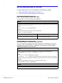
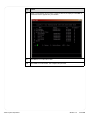
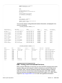
12.
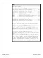
Verify that the blades booted successfully. Type:
# /nasmcd/sbin/getreason
Sample output for systems with 2 blades:
10 - slot_0 primary control station
5 - slot_2 contacted
5 - slot_3 contacted
If amber LEDs on the front or back of the storage system remain on for more than
10 minutes, make sure that the system is correctly cabled, and then refer to the
Troubleshooting Trees on the EMC Support page for the storage system. If you
cannot determine any reasons for the fault, contact your authorized service
provider.
Block
Follow the instructions below for your VNX5300 for block:
VNX™ System Operations
Step
Action
1.
Verify that the master switch/circuit breakers for each cabinet power strip are OFF.
2.
Ensure that the power cable for SP A is plugged into the SPS and power cord retention
bails are in place.
3.
Ensure that the power cord for SP B is plugged into the nearest power distribution unit
(PDU) on a different circuit from SPS A and that power cord retention bails are in place. In
a system with two SPSs, plug SP B into SPS B.
4.
Verify that the serial connection between management module A and the SPS is in place.
In a system with two SPSs, each management module has a serial connection to the
corresponding SPS.
5.
Verify that the power cables for the SPSs and any DAEs are plugged into the cabinet’s
power strips.
Release 7.0
15 of 114
Step
Action
6.
Turn the SPS power switches ON..
SPS power
switch B
SPS power
switch A
CIP-001115
7.
Ensure that any other devices in the cabinet are correctly installed and ready for power
up.
8.
Turn on the master switch/circuit breakers for each cabinet power strip.
In a 40U EMC cabinet, the master switches are on the power distribution panels (PDPs).
The storage system can take 10-12 minutes to complete a typical power up. Amber
warning LEDs flash during the power on self-test (POST) and then go off. The front fault
LED and the SPS recharge LEDs commonly stay on for several minutes while the SPSs
are charging.
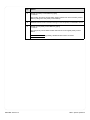
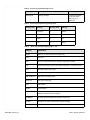
The powerup is complete when the SP power LED on each SP is steady green.
See "Location of Storage Processor power and status LEDs" on page 16.
If amber LEDs on the front or back of the storage system remain on for more than
10 minutes, make sure that the system is correctly cabled, and then refer to the
Troubleshooting Trees on the EMC Support page for the storage system. If you
cannot determine any reasons for the fault, contact your authorized service
provider.
Power
supply
Power supply
fault
8Gb 6Gb
fibre SAS
2
3
4
8Gb 6Gb
fibre SAS
1 X4
5
2
3
4
5
6Gb SAS
0 X4
SAS
port
status
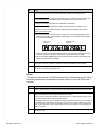
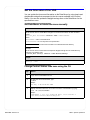
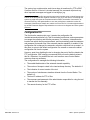
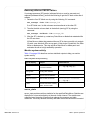
Figure 2
16 of 114 Release 7.0
3
2
1
0
3
2
1
0
3
2
1
0
3
1
0
B
2
Disk processor rear
A
1 X4
6Gb SAS
0 X4
SP
power
SP
fault/status
SAS
port
status
Location of Storage Processor power and status LEDs
VNX™ System Operations
VNX5500 powerup
The VNX5500 is available in three configurations: block, file, and unified. Follow the
instructions for your system configuration.
File/Unified
The VNX5500 for file and VNX5500 for unified can be configured with either one,
two, or three blades and one or two Control Stations.
Step
Action
1.
Verify that the master switch/circuit breakers for each cabinet power strip are ON. If you
are powering up the VNX5500 in a cabinet that contains other components, do not turn off
the cabinet circuit breakers. Ensure that the SPS switches are in the OFF position.
2.
Ensure that the power cable for SP A is plugged into the SPS and power cord retention
bails are in place.
3.
Ensure that the power cord for SP B is plugged into the nearest power distribution unit
(PDU) on a different circuit from SPS A and that power cord retention bails are in place. In
a system with two SPSs, plug SP B into SPS B.
4.
Verify that the power cables connecting each SPS is connected to the appropriate cabinet
power strip and that retention bails are in place.
5.
Verify that the power cables for any DAEs are plugged into the cabinet’s power strips.
6.
Turn the SPS power switches ON. .
SPS power
switch B
SPS power
switch A
CIP-001115
The storage array can take 10-12 minutes to complete a typical power up. Amber warning
LEDs flash during the power on self-test (POST) and then go off. The front fault LED and
the SPS recharge LEDs commonly stay on for several minutes while the SPSs are
charging.
7.
Connect the blade enclosure power cables to the PDU and wait for the blade(s) to power
up. The power LED on the front of the blade enclosure will light when the blades have
powered up.
8.
Wait 4-5 minutes as the blade(s) power up. This insures that the blades will have booted
up and that they are ready. Then connect the power cable for the Control Station 0 to the
PDU.
9.
Check the system power LED on the front of the Control Station. If that LED indicates that
Control Station 0 has not started to power up, turn on the Control Station by pressing the
power button on the front. Make sure that Control Station 0 is powered up before
continuing.
Note: The front bezel must be removed to access the power button of the Control Station.
VNX™ System Operations
Release 7.0
17 of 114
Step
Action
10.
Check the system and hardware status as follows:
a. From a browser, type the IP address of the primary Control Station.
b. Log in to the Unisphere software as sysadmin and define the scope as Global.
c. Use the drop-down list at the topleft Dashboard to select the system name and view its
System Information page.
d. On this page, verify that the Status fields for the VNX display OK.
11.
[Dual Control Station systems only]
Once you have confirmed that CS 0 is up and healthy, power up CS1.
12.
Verify that the blades booted successfully. Type:
# /nasmcd/sbin/getreason
Sample output for systems with 2 blades:
10 - slot_0 primary control station
5 - slot_2 contacted
5 - slot_3 contacted
If amber LEDs on the front or back of the storage system remain on for more than
10 minutes, make sure that the system is correctly cabled, and then refer to the
Troubleshooting Trees on the EMC Support page for the storage system. If you
cannot determine any reasons for the fault, contact your authorized service
provider.
Block
Follow the instructions below for your VNX5500 for block:
18 of 114 Release 7.0
Step
Action
1.
Verify that the master switch/circuit breakers for each cabinet power strip are OFF.
2.
Ensure that the power cable for SP A is plugged into the SPS and power cord retention
bails are in place.
3.
Ensure that the power cord for SP B is plugged into the nearest power distribution unit
(PDU) on a different circuit from SPS A and that power cord retention bails are in place. In
a system with two SPSs, plug SP B into SPS B.
4.
Verify that the serial connection between management module A and the SPS is in place.
In a system with two SPSs, each management module has a serial connection to the
corresponding SPS.
5.
Verify that the power cables for the SPSs and any DAEs are plugged into the cabinet’s
power strips.
VNX™ System Operations
Step
Action
6.
Turn the SPS power switches ON..
SPS power
switch B
SPS power
switch A
CIP-001115
7.
Ensure that any other devices in the cabinet are correctly installed and ready for power
up.
8.
Turn on the master switch/circuit breakers for each cabinet power strip.
In a 40U EMC cabinet, the master switches are on the power distribution panels (PDPs).
The storage system can take 10-12 minutes to complete a typical power up. Amber
warning LEDs flash during the power on self-test (POST) and then go off. The front fault
LED and the SPS recharge LEDs commonly stay on for several minutes while the SPSs
are charging.
The powerup is complete when the SP power LED on each SP is steady green.
See "Location of Storage Processor power and status LEDs" on page 19.
If amber LEDs on the front or back of the storage system remain on for more than
10 minutes, make sure that the system is correctly cabled, and then refer to the
Troubleshooting Trees on the EMC Support page for the storage system. If you
cannot determine any reasons for the fault, contact your authorized service
provider.
Power
supply
Power supply
fault
8Gb 6Gb
fibre SAS
2
3
4
8Gb 6Gb
fibre SAS
1 X4
5
2
3
4
5
Figure 3
VNX™ System Operations
A
3
2
1
1 X4
6Gb SAS
0 X4
SAS
port
status
0
3
2
1
0
3
2
1
0
3
1
0
B
2
Disk processor rear
6Gb SAS
0 X4
SP
power
SP
fault/status
SAS
port
status
Location of Storage Processor power and status LEDs
Release 7.0
19 of 114
VNX5700 powerup
The VNX5700 is available in three configurations: block, file, and unified. Follow the
instructions for your system configuration.
File/Unified
The VNX5700 for file and VNX5700 for unified can be configured with either two to
four blades and one or two Control Stations.
Step
Action
1.
Verify that the master switch/circuit breakers for each cabinet power strip are ON. If you
are powering up the VNX5700 in a cabinet that contains other components, do not turn off
the cabinet circuit breakers. Ensure that the SPS switches are in the OFF position.
2.
Ensure that the power cable for SP A is plugged into the SPS and power cord retention
bails are in place.
3.
Ensure that the power cable for SP B is plugged into the SPS and the power cord
retention bails are in place.
4.
Verify that the power cables connecting each SPS is connected to the appropriate cabinet
power strip and that retention bails are in place.
5.
Verify that the power cables for the DAE containing the vault drives [DAE0] are plugged in
to the SPS. Any other DAEs are plugged into the cabinet’s power strips.
6.
Turn the SPS power switches ON. .
SPS power
switch B
SPS power
switch A
CIP-001115
The storage array can take 10-12 minutes to complete a typical power up. Amber warning
LEDs flash during the power on self-test (POST) and then go off. The front fault LED and
the SPS recharge LEDs commonly stay on for several minutes while the SPSs are
charging.
7.
Connect the blade enclosure power cables to the PDU and wait for the blade(s) to power
up. The power LED on the front of the blade enclosure will light when the blades have
powered up.
8.
Wait 4-5 minutes as the blade(s) power up. This insures that the blades will have booted
up and that they are ready. Then connect the power cable for Control Station 0 to the
PDU.
9.
Check the system power LED on the front of the Control Station. If that LED indicates that
Control Station 0 has not started to power up, turn on the Control Station by pressing the
power button on the front. Make sure that Control Station 0 is powered up before
continuing.
Note: The front bezel must be removed to access the power button of the Control Station.
20 of 114 Release 7.0
VNX™ System Operations
Step
Action
10.
Check the system and hardware status as follows:
a. From a browser, type the IP address of the primary Control Station.
b. Log in to the Unisphere software as sysadmin and define the scope as Global.
c. Use the drop-down list at the topleft Dashboard to select the system name and view its
System Information page.
d. On this page, verify that the Status fields for the VNX display OK.
11.
[Dual Control Station systems only]
Once you have confirmed that CS 0 is up and healthy, power up CS1.
12.
Verify that the blades booted successfully. Type:
# /nasmcd/sbin/getreason
Sample output for systems with 2 blades:
10 - slot_0 primary control station
5 - slot_2 contacted
5 - slot_3 contacted
If amber LEDs on the front or back of the storage system remain on for more than
10 minutes, make sure that the system is correctly cabled, and then refer to the
Troubleshooting Trees on the EMC Support page for the storage system. If you
cannot determine any reasons for the fault, contact your authorized service
provider.
Block
Follow the instructions below for your VNX5700 for block:
VNX™ System Operations
Step
Action
1.
Verify that the master switch/circuit breakers for each cabinet power strip are OFF.
2.
Ensure that the power cable for SP A is plugged into the SPS and power cord retention
bails are in place.
3.
Ensure that the power cord for SP B is plugged into SPS B and power cord retention bails
are in place.
4.
Verify that the serial connection cables between the management modules on the
Storage Processors and the SPS are in place.
5.
Verify that the power cable for LCC A on the vault DAE (EA 0, bus 0) is plugged into the
SPS and the power cord retention bails are in place.
6.
Verify that the power cable for LCC B on the vault DAE s plugged into the SPS and the
power cord retention bails are in place.
7.
Verify that the power cables for the SPSs and any other DAEs are plugged into the
cabinet’s power strips.
Release 7.0
21 of 114
Step
Action
8.
Turn the SPS power switches ON..
SPS power
switch B
SPS power
switch A
CIP-001115
9.
Ensure that any other devices in the cabinet are correctly installed and ready for power
up.
10.
Turn on the master switch/circuit breakers for each cabinet power strip.
In a 40U EMC cabinet, the master switches are on the power distribution panels (PDPs).
The storage system can take 10-12 minutes to complete a typical power up. Amber
warning LEDs flash during the power on self-test (POST) and then go off. The front fault
LED and the SPS recharge LEDs commonly stay on for several minutes while the SPSs
are charging.
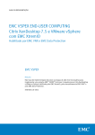
The powerup is complete when the SP power LED on each SP is steady green.
See "Location of Storage Processor power and status LEDs" on page 22.
If amber LEDs on the front or back of the storage system remain on for more than
10 minutes, make sure that the system is correctly cabled, and then refer to the
Troubleshooting Trees on the EMC Support page for the storage system. If you
cannot determine any reasons for the fault, contact your authorized service
provider.
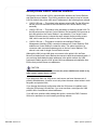
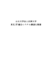
AC
AC
AC
AC
046-003-752_A01
Figure 4
22 of 114 Release 7.0
Location of Storage Processor power and status LEDs
VNX™ System Operations
VNX7500 powerup
The VNX7500 is available in three configurations: block, file, and unified. Follow the
instructions for your system configuration.
File/Unified
The VNX7500 for file and VNX7500 for unified can be configured with either two to
eight blades and one or two Control Stations.
Step
Action
1.
Verify that the master switch/circuit breakers for each cabinet power strip are ON. If you
are powering up the VNX7500 in a cabinet that contains other components, do not turn off
the cabinet circuit breakers. Ensure that the SPS switches are in the OFF position.
2.
Ensure that the power cable for SP A is plugged into the SPS and power cord retention
bails are in place.
3.
Ensure that the power cable for SP B is plugged into the SPS and the power cord
retention bails are in place.
4.
Verify that the power cables connecting each SPS is connected to the appropriate cabinet
power strip and that retention bails are in place.
5.
Verify that the power cables for the DAE containing the vault drives [DAE0] are plugged in
to the SPS. Any other DAEs are plugged into the cabinet’s power strips.
6.
Turn the SPS power switches ON. .
SPS power
switch B
SPS power
switch A
CIP-001115
The storage array can take 10-12 minutes to complete a typical power up. Amber warning
LEDs flash during the power on self-test (POST) and then go off. The front fault LED and
the SPS recharge LEDs commonly stay on for several minutes while the SPSs are
charging.
7.
Connect the blade enclosure power cables to the PDU and wait for the blade(s) to power
up. The power LED on the front of the blade enclosure will light when the blades have
powered up.
8.
Wait 4-5 minutes as the blade(s) power up. This insures that the blades will have booted
up and that they are ready. Then connect the power cable for Control Station 0 to the
PDU.
9.
Check the system power LED on the front of the Control Station. If that LED indicates that
Control Station 0 has not started to power up, turn on the Control Station by pressing the
power button on the front. Make sure that Control Station 0 is powered up before
continuing.
Note: The front bezel must be removed to access the power button of the Control Station.
VNX™ System Operations
Release 7.0
23 of 114
Step
Action
10.
Check the system and hardware status as follows:
a. From a browser, type the IP address of the primary Control Station.
b. Log in to the Unisphere software as sysadmin and define the scope as Global.
c. Use the drop-down list at the topleft Dashboard to select the system name and view its
System Information page.
d. On this page, verify that the Status fields for the VNX display OK.
11.
[Dual Control Station systems only]
Once you have confirmed that CS 0 is up and healthy, power up CS1.
12.
Verify that the blades booted successfully. Type:
# /nasmcd/sbin/getreason
Sample output for systems with 2 blades:
10 - slot_0 primary control station
5 - slot_2 contacted
5 - slot_3 contacted
If amber LEDs on the front or back of the storage system remain on for more than
10 minutes, make sure that the system is correctly cabled, and then refer to the
Troubleshooting Trees on the EMC Support page for the storage system. If you
cannot determine any reasons for the fault, contact your authorized service
provider.
Block
Follow the instructions below for your VNX7500 for block:
24 of 114 Release 7.0
Step
Action
1.
Verify that the master switch/circuit breakers for each cabinet power strip are OFF.
2.
Ensure that the power cable for SP A is plugged into the SPS and power cord retention
bails are in place.
3.
Ensure that the power cord for SP B is plugged into SPS B and power cord retention bails
are in place.
4.
Verify that the serial connection cables between the management modules on the
Storage Processors and the SPS are in place.
5.
Verify that the power cable for LCC A on the vault DAE (EA 0, bus 0) is plugged into the
SPS and the power cord retention bails are in place.
6.
Verify that the power cable for LCC B on the vault DAE s plugged into the SPS and the
power cord retention bails are in place.
7.
Verify that the power cables for the SPSs and any other DAEs are plugged into the
cabinet’s power strips.
VNX™ System Operations
Step
Action
8.
Turn the SPS power switches ON..
SPS power
switch B
SPS power
switch A
CIP-001115
9.
Ensure that any other devices in the cabinet are correctly installed and ready for power
up.
10.
Turn on the master switch/circuit breakers for each cabinet power strip.
In a 40U EMC cabinet, the master switches are on the power distribution panels (PDPs).
The storage system can take 10-12 minutes to complete a typical power up. Amber
warning LEDs flash during the power on self-test (POST) and then go off. The front fault
LED and the SPS recharge LEDs commonly stay on for several minutes while the SPSs
are charging.
The powerup is complete when the SP power LED on each SP is steady green.
See "Location of Storage Processor power and status LEDs" on page 25.
If amber LEDs on the front or back of the storage system remain on for more than
10 minutes, make sure that the system is correctly cabled, and then refer to the
Troubleshooting Trees on the EMC Support page for the storage system. If you
cannot determine any reasons for the fault, contact your authorized service
provider.
AC
AC
AC
AC
046-003-752_A01
Figure 5
VNX™ System Operations
Location of Storage Processor power and status LEDs
Release 7.0
25 of 114
Power down the VNX
Remove power from the VNX in an orderly way to protect data. Incorrectly powering
down the VNX can cause data loss or service disruption.
The tasks to power down the VNX Network Server after a planned power down or
after an emergency shutdown are:
26 of 114 Release 7.0
◆
"VNX VG2 and VG8 planned powerdown" on page 27
◆
"VNX5100 planned powerdown" on page 31
◆
"VNX5300 planned powerdown" on page 32
◆
"VNX5500 planned powerdown" on page 35
◆
"VNX5700 planned powerdown" on page 38
◆
"VNX7500 planned powerdown" on page 41
VNX™ System Operations
VNX VG2 and VG8 planned powerdown
Step
1.
Action
Do the following before you power down the server:
a. Notify all users of the planned powerdown several days in advance when possible.
b. Prevent all logins and notify all users several minutes in advance of the impending
powerdown.
c. Log out all users.
2.
To perform a planned powerdown, you should be within close proximity of the server.
Log in to the Control Station as root by using a HyperTerminal session:
• From the Start menu, select Programs > Accessories > Communications >
HyperTerminal.
• Type a session name and click OK.
• Select the COM port that the cable connects to in the Connect Using box and click OK.
• Type the following port settings:
• Bits per second: 19200
• Data bits: 8
• Parity: None
• Flow Control: None
• Emulation: Auto Detect
• Telnet terminal ID: ANSI
3.
Verify the system’s health, type:
$ /nas/bin/nas_checkup
The checkup command reports back on the state of the Control Station, Data Movers, and
storage system.
Note: This health check ensures that there are no major errors in the system that would
prevent the system from being turned on during the power up process.
4.
To halt the VNX for file server, type:
# /nasmcd/sbin/nas_halt now
ARE YOU SURE YOU WANT TO CONTINUE? [ yes or no ] :
# yes
Sending the halt signal to the Master Control Daemon...: Done
.
.
Halting system...
flushing ide devices: hda hdd
Power down.
It can take as long as 20 minutes to halt the server, depending on the configuration of the
VNX. Wait until the command completes before continuing. If the Control Station halted
successfully, the HyperTerminal session will be unresponsive.
If the Control Station restarts after the nas_halt command, then go to step 6. If the Control
Station has halted successfully, then go to the next step to restart the Control Station.
VNX™ System Operations
Release 7.0
27 of 114
Step
5.
Action
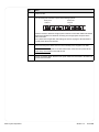
Restart the Control Station.
Restart the Control Station by pressing the Power button in the front of the Control
Station. To reach the Power button on the Control Station, you have to remove the front
bezel.
Control Station (front)
Power button
CNS-000876
Once the Control Station restarts, go on to the next step.
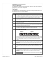
6.
Verify the shutdown of the blades:
Wait for 5 minutes, and then log in as root at the login prompt. Then verify the shutdown of
the blades by running the following command:
# /nasmcd/sbin/getreason
Sample output for a four blade configuration:
6 - slot_0 primary control station
- slot_2 powered off
- slot_3 powered off
- slot_4 powered off
- slot_5 powered off
7.
If you want to power down the storage array, follow the powerdown instructions in the
array documentation, at this time.
8.
Run the following command to halt the Control Station:
# /sbin/halt
Sample Output:
# /sbin/halt
Broadcast message from root (ttyS1) (Fri Feb 13 17:53:59 2009):
The system is going down for system halt NOW!
INIT: Stopping HAL daemon: [OK]
Stopping system message bus: [OK]
........
........
Halting system...
md: stopping all md devices.
md: md0 switched to read-only mode.
Shutdown: hda
System halted.
28 of 114 Release 7.0
VNX™ System Operations
Step
9.
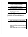
Action
Disconnect the blade enclosure power cords from the power distribution units (PDPs).
The blade enclosure power cables are labeled 3, 4, 5, and 6 in the following image.
Power distribution
panel (PDP)
Power distribution
panel (PDP)
2
CS 1
1
CS 0
6
2
3
3
2
1
2
2
1
0
#
#
3
2
2
1
2
0
10.
VNX™ System Operations
1
SP A
0
0
#
4
1
2
0
1
3
SP A
3
5
0
0
1
1
0
#
Disconnect each Control Station power cord from the power distribution units (PDPs). The
Control Station power cables are labeled 1 and 2 in the previous image.
Release 7.0
29 of 114
Step
11.
Action
Does the VG2 or VG8 server cabinet contain other equipment that is connected to the
cabinet PDPs and shared with other systems (such as Fibre Channel switches, storage
arrays, and so forth)?
If yes, stop here. The VG2 or VG8 server is powered down.
If no, go to the next step.
12.
Turn off (0 position) the left and right cabinet circuit-breaker switches located at the back
of the cabinet near the bottom to complete the powerdown of the VG2 or VG8 server.
Note: If the server is installed in a non-EMC cabinet, the switches are probably in a
different location.
!
CAUTION
To avoid service disruption to other clients, do not turn off the two cabinet circuitbreaker switches when the cabinet contains other equipment powered by these
switches that either services other clients or is not part of the VG2/VG8 server.
Cabinet
circuit-breaker
switches
I
ON
ON
I
O
OFF
OFF
O
Rear view
30 of 114 Release 7.0
CNS-000633
VNX™ System Operations
VNX5100 planned powerdown
The VNX5100 is available in one configuration: block. Follow the instructions for
your system configuration.
Block
The tasks to power down the VNX5100 include stopping I/O, halting the storage
processors, and powering down the system by using the SPS power switches.
Step
Action
1.
When possible, before you power down the VNX5100, notify all users of the powerdown.
2.
Stop all I/O activity to the Storage Processors in the DPE.
If the server connected to the DPE is running the Linux or UNIX operating system, back
up critical data and then unmount the file systems.
Stopping I/O allows the SP to destage cache data, and may take some time. The length of
time depends on criteria such as the size of the cache, the amount of data in the cache,
the type of data in the cache, and the target location on the disks, but it is typically less
than one minute.
3.
Wait 5 minutes.
4.
Use the SPS power switches to power off the storage system. .
SPS power
switch B
SPS power
switch A
CIP-001115
Wait two minutes to allow the storage system to write its cache to disk. Make sure that the
SPS power indicators are off before continuing.The storage system will power down
within 2 minutes.
For systems with a single SPS, after waiting two minutes, unplug the SP B and DAE 0
LCC B power cables from the PDU.
5.
Disconnect the power cables that run from the Standby Power Supplies to the DAE.
Note: This turns off the power to the SPS and the DPE. If the intent is to power off the
entire array, then shutdown each DAE as well.
6.
VNX™ System Operations
If there are multiple DAEs, disconnect the power cables from each DAE to the PDP. This
powers down the DAEs.
Release 7.0
31 of 114
VNX5300 planned powerdown
The VNX5300 is available in one configuration: block, file, and unified. Follow the
instructions for your system configuration.
File/Unified
The VNX5300 for file and VNX5300 for unified can be configured with either one or
two blades and one or two Control Stations.
Step
Action
1.
When possible, before you power down the VNX5300, be sure to notify all users of the
powerdown.
2.
Establish a HyperTerminal session and login to the Control Station at the serial console:
Connect a null modem DB9 serial cable from a Windows-based laptop or workstation to
the serial port on the Control Station
On the Windows client, open a HyperTerminal session
Select the COM port that the cable connects to in the Connect Using box and click OK
Enter the following port settings:
• Bits per second: 19200
• Data bits: 8
• Parity: None
• Flow Control: None
• Emulation: Auto Detect
• Telenet terminal ID: ANSI
From the Hyperterminal session, log into the Control Station as nasadmin and su to
root
3.
Verify the system’s health. Type:
# /nas/bin/nas_checkup
The checkup command reports back on the state of the control station, data movers,
and storage system.
Note: This healthcheck ensures that there are no major errors in the system that would
prevent the system from being turned on during the power up process.
This step will take several minutes.
4.
To halt the Control Station and all the blades, type the following:
# /nasmcd/sbin/nas_halt now
*************************** WARNING! **************************
You are about to HALT this VNX including all of its Control
Stations and Data Movers. DATA will be UNAVAILABLE when the
system is halted.
Note that this command does *not* halt the storage array.
ARE YOU SURE YOU WANT TO CONTINUE? [ yes or no ] :
5.
Type yes.
It can take as long as 20 minutes to halt the server, depending on the configuration of
the VNX system. Wait until the command completes before continuing. If the Control
Station halted successfully, the Hyper Terminal session will be unresponsive.
32 of 114 Release 7.0
VNX™ System Operations
Step
Action
6.
Unplug the power cables from the Control Station(s) and the blade enclosure’s power
supplies to the PDU.
6.
If you are powering down the system completely, shutdown the storage array:
Note: This step involves safely shutting down the SPs to preserve the write cache and
can be skipped if only the blade(s) and Control Station are to be powered down
a. Stop all I/O activity and wait five minutes before continuing.
Note: All I/O activity flowing from the blades was stopped when the blades were
shutdown in step 4. If external hosts are attached to the storage array, stop all I/O
activity from these hosts.
b. Use the SPS power switches to power off the array. Turn off (0 position) the power
switch on the standby power supplies (SPSs). Make sure the SPS power indicators
are off before continuing. .
SPS power
switch B
SPS power
switch A
CIP-001115
c. Wait two minutes to allow the storage system to write its cache to disk and to power
off. Then, disconnect the power cables that run from the SPSs to the DAE. For
systems with a single SPS, after waiting two minutes, unplug SP B and DAE 0 LCC B
power cables from the PDU.
d. If there are multiple DAEs present, disconnect the power cable from each DAE to the
PDU. This powers down the DAEs.
7.
Disconnect the power cables for each blade and Control Station from the PDUs.
8.
Make sure that the LEDs on all blade management switches are off. Once they are off,
the server is completely powered down.
Block
The tasks to power down the VNX5300 include stopping I/O, halting the storage
processors, and powering down the system by using the SPS power switches.
Step
Action
1.
When possible, before you power down the VNX5300, notify all users of the powerdown.
2.
Stop all I/O activity to the Storage Processors in the DPE.
If the server connected to the DPE is running the Linux or UNIX operating system, back
up critical data and then unmount the file systems.
Stopping I/O allows the SP to destage cache data, and may take some time. The length of
time depends on criteria such as the size of the cache, the amount of data in the cache,
the type of data in the cache, and the target location on the disks, but it is typically less
than one minute.
VNX™ System Operations
Release 7.0
33 of 114
Step
Action
3.
Wait 5 minutes.
4.
Use the SPS power switches to power off the storage system. .
SPS power
switch B
SPS power
switch A
CIP-001115
Wait two minutes to allow the storage system to write its cache to disk. Make sure that the
SPS power indicators are off before continuing.The storage system will power down
within 2 minutes.
For systems with a single SPS, after waiting two minutes, unplug the SP B and DAE 0
LCC B power cables from the PDU.
5.
Disconnect the power cables that run from the Standby Power Supplies to the DAE.
Note: This turns off the power to the SPS and the DPE. If the intent is to power off the
entire array, then shutdown each DAE as well.
6.
34 of 114 Release 7.0
If there are multiple DAEs, disconnect the power cables from each DAE to the PDP. This
powers down the DAEs.
VNX™ System Operations
VNX5500 planned powerdown
The VNX5500 is available in one configuration: block, file, and unified. Follow the
instructions for your system configuration.
File/Unified
The VNX5500 for file and VNX5500 for unified can be configured with either one,
two, or three blades and one or two Control Stations.
Step
Action
1.
When possible, before you power down the VNX5500, be sure to notify all users of the
powerdown.
2.
Establish a HyperTerminal session and login to the Control Station at the serial console:
Connect a null modem DB9 serial cable from a Windows-based laptop or workstation to
the serial port on the Control Station
On the Windows client, open a HyperTerminal session
Select the COM port that the cable connects to in the Connect Using box and click OK
Enter the following port settings:
• Bits per second: 19200
• Data bits: 8
• Parity: None
• Flow Control: None
• Emulation: Auto Detect
• Telenet terminal ID: ANSI
From the Hyperterminal session, log into the Control Station as nasadmin and su to
root
3.
Verify the system’s health. Type:
# /nas/bin/nas_checkup
The checkup command reports back on the state of the control station, data movers,
and storage system.
Note: This healthcheck ensures that there are no major errors in the system that would
prevent the system from being turned on during the power up process.
This step will take several minutes.
4.
To halt the Control Station and all the blades, type the following:
# /nasmcd/sbin/nas_halt now
*************************** WARNING! **************************
You are about to HALT this VNX including all of its Control
Stations and Data Movers. DATA will be UNAVAILABLE when the
system is halted.
Note that this command does *not* halt the storage array.
ARE YOU SURE YOU WANT TO CONTINUE? [ yes or no ] :
5.
Type yes.
It can take as long as 20 minutes to halt the server, depending on the configuration of
the VNX system. Wait until the command completes before continuing. If the Control
Station halted successfully, the Hyper Terminal session will be unresponsive.
VNX™ System Operations
Release 7.0
35 of 114
Step
Action
6.
Unplug the power cables from the Control Station(s) and the blade enclosure’s power
supplies to the PDU.
6.
If you are powering down the system completely, shutdown the storage array:
Note: This step involves safely shutting down the SPs to preserve the write cache and
can be skipped if only the blade(s) and Control Station are to be powered down
a. Stop all I/O activity and wait five minutes before continuing.
Note: All I/O activity flowing from the blades was stopped when the blades were
shutdown in step 4. If external hosts are attached to the storage array, stop all I/O
activity from these hosts.
b. Use the SPS power switches to power off the array. Turn off (0 position) the power
switch on the standby power supplies (SPSs). Make sure the SPS power indicators
are off before continuing. .
SPS power
switch B
SPS power
switch A
CIP-001115
c. Wait two minutes to allow the storage system to write its cache to disk and to power
off. Then, disconnect the power cables that run from the SPSs to the DAE. For
systems with a single SPS, after waiting two minutes, unplug SP B and DAE 0 LCC B
power cables from the PDU.
d. If there are multiple DAEs present, disconnect the power cable from each DAE to the
PDU. This powers down the DAEs.
7.
Disconnect the power cables for each blade and Control Station from the PDUs.
8.
Make sure that the LEDs on all blade management switches are off. Once they are off,
the server is completely powered down.
Block
The tasks to power down the VNX5500 include stopping I/O, halting the storage
processors, and powering down the system by using the SPS power switches.
Step
Action
1.
When possible, before you power down the VNX5500, notify all users of the powerdown.
2.
Stop all I/O activity to the Storage Processors in the DPE.
If the server connected to the DPE is running the Linux or UNIX operating system, back
up critical data and then unmount the file systems.
Stopping I/O allows the SP to destage cache data, and may take some time. The length of
time depends on criteria such as the size of the cache, the amount of data in the cache,
the type of data in the cache, and the target location on the disks, but it is typically less
than one minute.
36 of 114 Release 7.0
VNX™ System Operations
Step
Action
3.
Wait 5 minutes.
4.
Use the SPS power switches to power off the storage system. .
SPS power
switch B
SPS power
switch A
CIP-001115
Wait two minutes to allow the storage system to write its cache to disk. Make sure that the
SPS power indicators are off before continuing.The storage system will power down
within 2 minutes.
For systems with a single SPS, after waiting two minutes, unplug the SP B and DAE 0
LCC B power cables from the PDU.
5.
Disconnect the power cables that run from the Standby Power Supplies to the DAE.
Note: This turns off the power to the SPS and the DPE. If the intent is to power off the
entire array, then shutdown each DAE as well.
6.
VNX™ System Operations
If there are multiple DAEs, disconnect the power cables from each DAE to the PDP. This
powers down the DAEs.
Release 7.0
37 of 114
VNX5700 planned powerdown
The VNX5700 is available in one configuration: block, file, and unified. Follow the
instructions for your system configuration.
File/Unified
The VNX5700 for file and VNX5700 for unified can be configured with either two to
four blades and one or two Control Stations.
Step
Action
1.
When possible, before you power down the VNX5700, be sure to notify all users of the
powerdown.
2.
Establish a HyperTerminal session and login to the Control Station at the serial console:
• Connect a null modem DB9 serial cable from a Windows-based laptop or workstation
to the serial port on the Control Station
• On the Windows client, open a HyperTerminal session
• Select the COM port that the cable connects to in the Connect Using box and click
OK
• Enter the following port settings:
• Bits per second: 19200
• Data bits: 8
• Parity: None
• Flow Control: None
• Emulation: Auto Detect
• Telenet terminal ID: ANSI
From the Hyperterminal session, log into the Control Station as nasadmin and su to
root
3.
Verify the system’s health. Type:
# /nas/bin/nas_checkup
The checkup command reports back on the state of the control station, data movers,
and storage system.
Note: This healthcheck ensures that there are no major errors in the system that would
prevent the system from being turned on during the power up process.
This step will take several minutes.
4.
To halt the Control Station and all the blades, type the following:
# /nasmcd/sbin/nas_halt now
************************* WARNING! ************************
You are about to HALT this VNX including all of its Control
Stations and Data Movers. DATA will be UNAVAILABLE when the
system is halted.
Note that this command does *not* halt the storage array.
ARE YOU SURE YOU WANT TO CONTINUE? [ yes or no ] :
5.
Type yes.
It can take as long as 20 minutes to halt the server, depending on the configuration of
the VNX system. Wait until the command completes before continuing. If the Control
Station halted successfully, the Hyper Terminal session will be unresponsive.
38 of 114 Release 7.0
VNX™ System Operations
Step
Action
6.
If you are powering down the system completely, shutdown the storage array:
Note: This step involves safely shutting down the SPs to preserve the write cache and
can be skipped if only the blade(s) and Control Station are to be powered down
a. Stop all I/O activity and wait five minutes before continuing.
Note: All I/O activity flowing from the blades was stopped when the blades were
shutdown in step 4. If external hosts are attached to the storage array, stop all I/O
activity from these hosts.
b. Use the SPS power switches to power off the array. Turn off (0 position) the power
switch on the standby power supplies (SPSs). Make sure the SPS power indicators
are off before continuing.
SPS power
switch B
SPS power
switch A
CIP-001115
c. Wait two minutes to allow the storage system to write its cache to disk and to power
off. Then, disconnect the power cables that run from the SPSs to the DAE.
d. If there are multiple DAEs present, disconnect the power cable from each DAE to the
PDU. This powers down the DAEs.
7.
Disconnect the power cables for each blade and Control Station from the PDUs.
8.
Make sure that the LEDs on all blade management switches are off. Once they are off,
the server is completely powered down.
Block
The tasks to power down the VNX5700 storage system include stopping I/O, halting
the storage processors, and powering down the system by using the SPS power
switches.
Step
Action
1.
When possible, before you power down the VNX5700, notify all users of the powerdown.
2.
Stop all I/O activity to the Storage Processors in the SPE.
If the server connected to the SPE is running the Linux or UNIX operating system, back
up critical data and then unmount the file systems.
Stopping I/O allows the SP to destage cache data, and may take some time. The length of
time depends on criteria such as the size of the cache, the amount of data in the cache,
the type of data in the cache, and the target location on the disks, but it is typically less
than one minute.
3.
VNX™ System Operations
Wait 5 minutes.
Release 7.0
39 of 114
Step
Action
4.
Use the SPS power switches to power off the storage system.
SPS power
switch B
SPS power
switch A
CIP-001115
Wait two minutes to allow the storage system to write its cache to disk. Make sure that the
SPS power indicators are off before continuing. The storage system will power down
within 2 minutes.
!
CAUTION
Never unplug the power supplies to shut down an SPE. Bypassing the SPS in that
manner prevents the storage system from saving write cache data to the vault
drives, and results in data loss. You will lose access to data, and the storage
processor log displays an error message similar to the following:
Enclosure 0 Disk 5 0x90a (Can’t Assign - Cache Dirty)
0 0xafb40 0x14362c
Contact your service provider if this situation occurs.
5.
Disconnect the power cables that run from the Standby Power Supplies to the DAE.
Note: This turns off the power to the SPS and the DAE. If the intent is to power off the
entire array, then shutdown each DAE as well.
This turns off power to the SPE and the first DAE (EA 0, bus 0). If the intent is to power off
the entire array, then shutdown each DAE as well.
6.
40 of 114 Release 7.0
If there are multiple DAEs, disconnect the power cables from each DAE to the PDP. This
powers down the DAEs..
VNX™ System Operations
VNX7500 planned powerdown
The VNX7500 is available in one configuration: block, file, and unified. Follow the
instructions for your system configuration.
File/Unified
The VNX7500 for file and VNX7500 for unified can be configured with either two to
eight blades and one or two Control Stations.
Step
Action
1.
When possible, before you power down the VNX7500, be sure to notify all users of the
powerdown.
2.
Establish a HyperTerminal session and login to the Control Station at the serial console:
• Connect a null modem DB9 serial cable from a Windows-based laptop or workstation
to the serial port on the Control Station
• On the Windows client, open a HyperTerminal session
• Select the COM port that the cable connects to in the Connect Using box and click
OK
• Enter the following port settings:
• Bits per second: 19200
• Data bits: 8
• Parity: None
• Flow Control: None
• Emulation: Auto Detect
• Telenet terminal ID: ANSI
From the Hyperterminal session, log into the Control Station as nasadmin and su to
root
3.
Verify the system’s health. Type:
# /nas/bin/nas_checkup
The checkup command reports back on the state of the control station, data movers,
and storage system.
Note: This healthcheck ensures that there are no major errors in the system that would
prevent the system from being turned on during the power up process.
This step will take several minutes.
4.
To halt the Control Station and all the blades, type the following:
# /nasmcd/sbin/nas_halt now
************************* WARNING! ************************
You are about to HALT this VNX including all of its Control
Stations and Data Movers. DATA will be UNAVAILABLE when the
system is halted.
Note that this command does *not* halt the storage array.
ARE YOU SURE YOU WANT TO CONTINUE? [ yes or no ] :
5.
Type yes.
It can take as long as 20 minutes to halt the server, depending on the configuration of
the VNX system. Wait until the command completes before continuing. If the Control
Station halted successfully, the Hyper Terminal session will be unresponsive.
VNX™ System Operations
Release 7.0
41 of 114
Step
Action
6.
If you are powering down the system completely, shutdown the storage array:
Note: This step involves safely shutting down the SPs to preserve the write cache and
can be skipped if only the blade(s) and Control Station are to be powered down
a. Stop all I/O activity and wait five minutes before continuing.
Note: All I/O activity flowing from the blades was stopped when the blades were
shutdown in step 4. If external hosts are attached to the storage array, stop all I/O
activity from these hosts.
b. Use the SPS power switches to power off the array. Turn off (0 position) the power
switch on the standby power supplies (SPSs). Make sure the SPS power indicators
are off before continuing.
SPS power
switch B
SPS power
switch A
CIP-001115
c. Wait two minutes to allow the storage system to write its cache to disk and to power
off. Then, disconnect the power cables that run from the SPSs to the DAE.
d. If there are multiple DAEs present, disconnect the power cable from each DAE to the
PDU. This powers down the DAEs.
7.
Disconnect the power cables for each blade and Control Station from the PDUs.
8.
Make sure that the LEDs on all blade management switches are off. Once they are off,
the server is completely powered down.
Block
The tasks to power down the VNX7500 storage system include stopping I/O, halting
the storage processors, and powering down the system by using the SPS power
switches.
Step
Action
1.
When possible, before you power down the VNX7500, notify all users of the powerdown.
2.
Stop all I/O activity to the Storage Processors in the SPE.
If the server connected to the SPE is running the Linux or UNIX operating system, back
up critical data and then unmount the file systems.
Stopping I/O allows the SP to destage cache data, and may take some time. The length of
time depends on criteria such as the size of the cache, the amount of data in the cache,
the type of data in the cache, and the target location on the disks, but it is typically less
than one minute.
3.
42 of 114 Release 7.0
Wait 5 minutes.
VNX™ System Operations
Step
Action
4.
Use the SPS power switches to power off the storage system.
SPS power
switch B
SPS power
switch A
CIP-001115
Wait two minutes to allow the storage system to write its cache to disk. Make sure that the
SPS power indicators are off before continuing. The storage system will power down
within 2 minutes.
!
CAUTION
Never unplug the power supplies to shut down an SPE. Bypassing the SPS in that
manner prevents the storage system from saving write cache data to the vault
drives, and results in data loss. You will lose access to data, and the storage
processor log displays an error message similar to the following:
Enclosure 0 Disk 5 0x90a (Can’t Assign - Cache Dirty)
0 0xafb40 0x14362c
Contact your service provider if this situation occurs.
5.
Disconnect the power cables that run from the Standby Power Supplies to the DAE.
Note: This turns off the power to the SPS and the DAE. If the intent is to power off the
entire array, then shutdown each DAE as well.
This turns off power to the SPE and the first DAE (EA 0, bus 0). If the intent is to power off
the entire array, then shutdown each DAE as well.
6.
VNX™ System Operations
If there are multiple DAEs, disconnect the power cables from each DAE to the PDP. This
powers down the DAEs..
Release 7.0
43 of 114
Shut down the VNX in an emergency
This section explains how to shut down the VNX in case of an emergency. "Power
down the VNX" on page 26 provides more specifics on normal (planned)
powerdown procedures.
Perform the following tasks to shut down the VNX in an emergency:
!
!
CAUTION
These procedures can cause data loss or disrupt service to other clients. Use these
procedures only when faced with personal hazard or possible property damage.
VNX series emergency shutdown
To shut down VNX Unified, Integrated, and Gateway servers in an emergency, turn
off the two cabinet circuit-breaker switches.
Note: Turning off the cabinet circuit-breakers immediately removes power from Data
Movers, Control Station, storage array system, standby power supplies (SPSs), and any
other equipment connected to the cabinet’s PDU. No other action is required.
44 of 114 Release 7.0
VNX™ System Operations
Power up after an emergency shutdown
After you use the emergency shutdown procedure, you might encounter errors or
problems when you try to restart the VNX server. If this occurs, record any error
messages and contact the EMC Customer Service immediately.
To power up a server after an emergency shutdown, follow the "Power up the VNX"
on page 9.
VNX™ System Operations
Release 7.0
45 of 114
Halt the Control Station
This section explains how to perform an orderly halt of Control Stations in Unified,
Integrated, and Gateway servers. You can halt a Control Station either locally or
remotely.
Perform these tasks to halt Control Stations either locally or remotely:
◆
"Locally halt one Control Station" on page 46
◆
"Locally halt two Control Stations" on page 46
◆
"Remotely halt one Control Station" on page 47
◆
"Remotely halt two Control Stations" on page 47
Locally halt one Control Station
This procedure applies to all VNX unified and VNX for file systems with a single
Control Station.
Step
Action
1.
Log in to the server as root.
2.
Halt the Control Station by typing:
# /sbin/halt
The Control Station halts.
Locally halt two Control Stations
This procedure applies to all VNX unified and VNX for file systems with two Control
Stations. Always halt the secondary Control Station before the primary.
Step
Action
1.
Log in to the server as root.
2.
Determine which Control Station (CS_0 or CS_1) is primary and which is secondary by
typing:
# /nasmcd/getreason
The primary Control Station returns a reason code of 10; the secondary Control Station
returns a reason code of 11.
3.
Log in to the secondary Control Station as root.
4.
Halt the secondary Control Station by typing:
# /sbin/halt
The secondary Control Station halts.
5.
46 of 114 Release 7.0
Log in to the primary Control Station as root.
VNX™ System Operations
Step
6.
Action
Halt the primary Control Station by typing:
# /sbin/halt
The primary Control Station halts.
Remotely halt one Control Station
This procedure applies to all VNX unified and VNX for file systems single Control
Station. After locally or remotely halting the Control Station, use the VNX cabinet
console to restart the Control Station.
Step
Action
1.
Use a secure, encrypted, remote login application to log in to the server as root.
2.
Halt the Control Station by typing:
# /sbin/halt
The Control Station halts.
Remotely halt two Control Stations
This procedure applies to all VNX unified and VNX for file systems with two Control
Stations.
Step
Action
1.
Use a secure, encrypted, remote login application to log in to the server as root.
2.
Determine which Control Station (CS_0 or CS_1) is primary and which is secondary by
typing:
$ /nasmcd/getreason
The primary Control Station returns a reason code of 10; the secondary Control Station
returns a reason code of 11.
3.
Log in to the secondary Control Station as root.
4.
Halt the secondary Control Station by typing:
# /sbin/halt
The secondary Control Station halts.
5.
Establish another remote connection and log in to the primary Control Station as root.
6.
Halt the primary Control Station by typing:
# /sbin/halt
The primary Control Station halts.
VNX™ System Operations
Release 7.0
47 of 114
Restart the Control Station
This section explains how to perform an orderly restart of Control Station(s) in a
VNX unified and VNX for file systems. Control Stations restart either locally or
remotely.
Perform these tasks to restart Control Stations either locally or remotely:
◆
"Locally restart one Control Station" on page 48
◆
"Locally restart two Control Stations" on page 48
◆
"Remotely restart one Control Station" on page 49
◆
"Remotely restart two Control Stations" on page 49
Locally restart one Control Station
This restart procedure applies to all VNX unified and VNX for file systems with a
single Control Station.
Step
Action
1.
Use a secure, encrypted, remote login application to log in to the server as root.
2.
Restart the Control Station by typing:
# reboot
The Control Station restarts.
Locally restart two Control Stations
This restart procedure applies to all VNX unified and VNX for file systems with two
Control Stations.
Step
Action
1.
Use a secure, encrypted, remote login application to log in to the server as root.
2.
Determine which Control Station (CS_0 or CS_1) is primary and which is secondary by
typing:
$ /nasmcd/getreason
The primary Control Station returns a reason code of 10; the secondary Control Station
returns a reason code of 11.
48 of 114 Release 7.0
3.
Log in to the primary Control Station.
4.
Change to root and type the root password.
VNX™ System Operations
Step
5.
Action
Restart the primary Control Station by typing:
# reboot
The primary Control Station restarts and fails over to the secondary Control Station
(making it the new primary Control Station).
Do not go to the next step until the Control Station has finished restarting.
6.
Log in to the new primary Control Station.
7.
Change to root and type the root password.
8.
Restart the new primary Control Station by typing:
# reboot
The new primary Control Station restarts and fails over to the original primary Control
Station.
Remotely restart one Control Station
This procedure applies to all VNX unified and VNX for file systems with a single
Control Station.
Step
Action
1.
Use a secure, encrypted, remote login application to log in to the server as root.
2.
Restart the Control Station by typing:
# reboot
The Control Station restarts.
Note: To continue working remotely, establish another remote connection.
Remotely restart two Control Stations
This procedure applies to all VNX unified and VNX for file systems with two Control
Stations.
Step
1.
Action
Use a secure, encrypted, remote login application to log in to the server as root.
Determine which Control Station (CS_0 or CS_1) is primary and which is secondary by
typing:
$ /nasmcd/getreason
The primary Control Station returns a reason code of 10; the secondary Control Station
returns a reason code of 11.
2.
VNX™ System Operations
From the primary Control Station, change to root and type the root password.
Release 7.0
49 of 114
Step
3.
Action
Restart the primary Control Station by typing:
# reboot
After a while, the primary Control Station restarts and fails over to the secondary Control
Station (making it the new primary Control Station).
4.
Establish another remote connection and log in to the new primary Control Station as root.
5.
Restart the new primary Control Station by typing:
# reboot
The new primary Control Station restarts and fails over to the original primary Control
Station.
Note: To continue working remotely, establish another remote connection.
50 of 114 Release 7.0
VNX™ System Operations
Halt the Data Movers
The following procedure explains how to perform an orderly, timed, or immediate
halt of a network server’s Data Mover or blade. This procedure applies to all VNX
unified and VNX for file systems.
Note: A Data Mover for a VNX for file server is also called a blade. There is no functional
difference between a Data Mover and a blade. They both serve the same purpose in a VNX
for file server.
Action
To immediately halt a Data Mover or blade, use this command syntax:
$ server_cpu <movername> -halt <time>
where:
<movername> = name of the Data Mover or blade
<time> = when the Data Mover or blade is to be halted, specified as one of the following:
{ now | +<min> | <hour>:<min> }
Example:
To halt server_5 immediately, type:
$ server_cpu server_5 -halt now
Output
server_5 : done
VNX™ System Operations
Release 7.0
51 of 114
Restart a Data Mover
The following procedure explains how to perform an orderly, timed or immediate
restart of the network server’s Data Movers or blades. The procedure applies to all
VNX unified and VNX for file systems.
Action
To immediately restart and monitor a Data Mover or blade, use this command syntax:
$ server_cpu <movername> -reboot [cold|warm] -monitor <time>
where:
<movername> = name of the Data Mover or blade
[cold|warm]= defines the degree to which the Data Mover is reset.
• A cold reboot or a hardware reset shuts down the Data Mover completely before restarting,
including a Power on Self Test (POST).
• A warm reboot or a software reset performs a partial shutdown of the Data Mover, and skips
the POST after restarting. A software reset is faster than the hardware reset.
<time> = when the Data Mover or blade is to be restarted, specified as one of the following:
{ now | +<min> | <hour>:<min> }
Note: The default parameter of the -reboot option will be the warm parameter. In case the warm
rebooting fails, the -reboot option will use the cold parameter to reboot the Data Mover. To monitor
an immediate cold restart of server_5, type:
$ server_cpu server_5 -reboot cold -monitor now
Example 2:
To monitor an immediate warm restart of server_5, type:
$ server_cpu server_5 -reboot -monitor now
Output
Note
server_5 : reboot in progress .....
3.4.4.done
You can verify when the system is back online
by using /nas/sbin/getreason.
Code 5 indicates the Data Mover or blade is
available.
You might also see the following codes as the
Data Mover or blade restarts:
• 0 - (reset) - Data Mover or blade performing
BIOS check, then begins boot sequence
• 1 - (POST pass) - Data Mover or blade
passes POST
• 3 - (loaded) - Operating system loaded and
initializing
• 4 - (ready) - Operating system initialized
• 5 - (contacted) - Data Mover or blade
available
52 of 114 Release 7.0
VNX™ System Operations
Check the system status
Use the nas_checkup command to perform a health checkup for the VNX.
nas_checkup runs scheduled and unscheduled health checks on the VNX and
reports problems that are found, and the actions needed to fix the problem and acts
as a system health monitor.
The scheduled run time for the nas_checkup command is every 2 weeks by default.
If a warning or error is discovered during this time, an alert is posted on the
Unisphere software.
Set up email notification for warnings or errors in the Unisphere software
Notifications page, or modify and load the sample nas_checkup event configuration
file.
nas_checkup returns one of the following exit statuses for system diagnostics:
◆
0 — No problems found
◆
1 — nas_checkup posted information
◆
2 — nas_checkup discovered a warning
◆
3 — nas_checkup discovered an error
◆
255 — Any other error
Examples of errors that could cause a 255 exit status include, but are not limited to:
◆
If nas_checkup is run when another instance of nas_checkup is running
◆
If nas_checkup is run by someone other than root or the administrator group
(generally nasadmin)
◆
If nas_checkup is run on the standby Control Station
If a problem is discovered that requires EMC Service Personnel assistance,
nas_checkup will notify EMC.
Action
To perform a checkup of the VNX for file, use this command syntax:
$ nas_checkup
VNX™ System Operations
Release 7.0
53 of 114
Output
Check Version:6.0.36.0
Check Command:/nas/bin/nas_checkup
Check Log
:/nas/log/checkup-run.100527-135002.log
---------------------------------Checks--------------------------------Control Station: Checking statistics groups database............... Pass
Control Station: Checking if file system usage is under limit....... Pass
Control Station: Checking if NAS Storage API is installed correctly. Pass
Control Station: Checking if NBS service is started................ Pass
Control Station: Checking if PXE service is stopped................ Pass
...
Blades
: Checking boot files............................... Pass
Blades
: Checking if primary is active..................... Pass
Blades
: Checking if root filesystem is too large.......... Pass
Blades
: Checking if root filesystem has enough free space. Pass
Blades
: Checking if using standard DART image............. Pass
...
Storage System : Checking disk emulation type...................... Pass
Storage System : Checking disk high availability access............ Pass
Storage System : Checking disks read cache enabled................. Pass
Storage System : Checking if access logix is enabled............... Pass
...
-----------------------------------------------------------------------One or more errors have occurred. Follow the instructions provided to
correct the problem and try again.
------------------------------Information------------------------------Blades : Check if each primary Blade has standby
Information HC_DM_27390050394: The following primary Blade(s)
server_2, server_3 do(es) not have a standby Blade configured. It is
recommended that each primary Blade have a standby configured for it
with automatic failover policy for high availability.
-------------------------------------------------------------------------------------------------------Warnings-------------------------------Control Station: Check all callhome files delivered
Warning HC_CS_18800050326: There are 13 undelivered Call Home incidents
in the /nas/log/ConnectHome directory(es)
Action :
Check the /nas/log/connectemc/ConnectEMC log to ensure the connection
is established correctly. To test your Callhome configuration, you can
run /nas/sbin/nas_connecthome -test { -email_1 | -email_2 | -ftp_1 |
-ftp_2 | -modem_1 | -modem_2 } command. View the RSC*.xml files under
the /nas/log/ConnectHome directory(es) and inspect the CDATA content
to find out and possibly resolve the problem. To remove the call home
incidents, run the command "/nas/sbin/nas_connecthome -service clear".
Otherwise escalate this issue through your support organization.
------------------------------------------------------------------------
54 of 114 Release 7.0
VNX™ System Operations
Back up the VNX database
VNX database created by the VNX software during installation is stored on disk in
the Control Station. The VNX database maintains vital information required for each
Data Mover or blade. The VNX for file software automatically creates a VNX
database backup file 1 minute after each hour. You can manually create a VNX
database backup file at any time.
Perform these tasks to back up the VNX database:
◆
"Automatic VNX database backup" on page 55
◆
"Manual VNX database backup" on page 56
!
!
CAUTION
◆
EMC strongly recommends that you regularly copy the VNX database backup file
from the Control Station and save it to a remote location for safe keeping. Always
copy the VNX database backup file when hardware or software upgrades are
planned.
◆
Only EMC qualified support personnel should restore the VNX database by using
the VNX database backup file.
◆
Do not manually edit the nas_db database without consulting Customer Service.
Any changes you make might disrupt services.
Automatic VNX database backup
The VNX automatically backs up the entire database and saves it to a file named
nasdb_backup.1.tar.gz. in the /home/nasadmin directory. It does this 1 minute after
each hour. It also maintains the last 12 backup files.
To copy a VNX database backup file to a remote location, use FTP as described in
Using FTP and TFTP on VNX .
VNX™ System Operations
Release 7.0
55 of 114
Manual VNX database backup
Use this procedure to back up and save a copy of the VNX database without
waiting for an hourly automatic backup.
Step
Action
1.
Log in to the network server.
2.
List the VNX database backup files by typing:
$ ls –l nasdb*
A display similar to the following appears:
-rw-r--r-1 nasadmin nasadmin
nasdb_backup.1.tar.gz
-rw-r--r-1 nasadmin root
nasdb_backup.b.tar.gz
1920308 May
4 12:03
1022219 Mar 23 19:32
Ensure that a version of nasdb_backup.1.tar is listed with the current date and time. If a
current version is not present, ensure that nasadmin is the group and owner of
nasdb_backup.1.tar.gz and _nasbkup.
3.
To ensure that the VNX database backup does not fill the root file system, check the root
file system free space by typing:
$ df -k /
The system returns the amount of space in the root directory in kilobytes (KB). Ensure
that the free space is more than the size of the most recent VNX database backup.
4.
Create a backup file of the VNX database by using this command syntax:
$ /nas/sbin/nasdb_backup /nas /celerra/backup <yymmdd>
where <yymmdd> is the last two digits of the current year, the two-digit month, and the
two-digit day.
The following appears:
NAS_DB backup in progress .....NAS_DB checkpoint in
progress.....done
56 of 114 Release 7.0
VNX™ System Operations
Step
5.
Action
Examine the date and time to verify that a new version of
nasdb_backup.<yymmdd>.tar.gz was created by typing:
$ ls -l celerra/backup*
A display similar to the following appears:
total 46208
-rw-r--r-- 1 nasadmin nasadmin 2700 Feb 5 13:01
_dbms_backup.01.tar.gz
-rw-r--r-- 1 nasadmin nasadmin 2702 Feb 5 14:01
_dbms_backup.02.tar.gz
-rw-r--r-- 1 nasadmin nasadmin 2702 Feb 5 14:01
_dbms_backup.OK.tar.gz
drwx------ 2 root root 16384 Feb 1 11:27 lost+found
-rw-r--r-- 1 nasadmin nasadmin 3163954 Feb 5 13:01
_nasbkup.01.tar.gz
-rw-r--r-- 1 nasadmin nasadmin 3163960 Feb 5 14:01
_nasbkup.02.tar.gz
-rw-r--r-- 1 nasadmin nasadmin 3163941 Feb 5 03:01
_nasbkup.03.tar.gz
-rw-r--r-- 1 nasadmin nasadmin 3163965 Feb 5 04:01
_nasbkup.04.tar.gz
-rw-r--r-- 1 nasadmin nasadmin 3163959 Feb 5 05:01
_nasbkup.05.tar.gz
-rw-r--r-- 1 nasadmin nasadmin 3163934 Feb 5 06:01
_nasbkup.06.tar.gz
-rw-r--r-- 1 nasadmin nasadmin 3163945 Feb 5 07:01
_nasbkup.07.tar.gz
-rw-r--r-- 1 nasadmin nasadmin 3163957 Feb 5 08:01
_nasbkup.08.tar.gz
-rw-r--r-- 1 nasadmin nasadmin 3163964 Feb 5 09:01
_nasbkup.09.tar.gz
-rw-r--r-- 1 nasadmin nasadmin 3163922 Feb 5 10:01
_nasbkup.10.tar.gz
-rw-r--r-- 1 nasadmin nasadmin 3163960 Feb 5 11:01
_nasbkup.11.tar.gz
-rw-r--r-- 1 nasadmin nasadmin 3163954 Feb 5 12:01
_nasbkup.12.tar.gz
-rw-r--r-- 1 nasadmin nasadmin 4407468 Feb 5 14:01
nasdb_backup.1.tar.gz
-rw-r--r-- 1 nasadmin nasadmin 4268888 Feb 1 11:33
nasdb_backup.b.tar.gz
drwxrwxr-x 2 root root 4096 Feb 1 12:01 SCCS
-rwx------ 1 root root 528384 Feb 1 12:01 wpart
6.
Using secure FTP, copy the VNX database file nasdb_backup.<yymmdd>.tar.gz and
nasdb_backup.b.tar.gz to a remote location.
Note: The backup file should not be copied to the Data Mover because Data Movers might
not be functional if VNX database gets corrupted.
VNX™ System Operations
Release 7.0
57 of 114
Verify the daemons
After installation, daemons begin running on the Control Station at all times. If for
some reason the daemons become disabled, certain server facilities might fail.
Perform these tasks to verify whether VNX daemons are enabled:
◆
"View VNX daemons" on page 58
◆
"View HTTPD daemons" on page 58
View VNX daemons
Action
To view the VNX daemons enabled at the Control Station, type:
$ ps -e|grep nas | awk ' { print $4 } ' | sort | uniq
Output
Note
nas_boxmonitor
nas_eventcollec
nas_eventlog
nas_mcd
nas_watchdog
The complete list of daemons is displayed in the Output column of
the table. The output list for the server might be different.
If the daemons are not running, restart them by typing:
/etc/rc.d/init.d/nas stop
/etc/rc.d/init.d/nas star
View HTTPD daemons
It is essential that the HTTPD daemons run on the Control Station at all times, so
the Unisphere software can manage the VNX.
Action
To view whether the HTTPD daemons are enabled at the Control Station and to reenable them if
necessary, type:
$ ps -e|grep httpd
Output
15937
15949
15950
15951
15964
15965
15966
15995
16008
58 of 114 Release 7.0
Note
?
?
?
?
?
?
?
?
?
00:00:10
00:00:00
00:00:00
00:00:00
00:00:00
00:00:00
00:00:00
00:00:00
00:00:00
httpd
httpd
httpd
httpd
httpd
httpd
httpd
httpd
httpd
If the HTTPD daemons are not running, restart
the Unisphere software by switching to root
and typing:
/nas/http/nas_ezadm/etc/script
restart
VNX™ System Operations
Discover SCSI devices
The Control Station database maintains a list of all SCSI devices. When required,
you can probe the storage system to discover and save the present SCSI devices
for a specific Data Mover.
Action
To discover all SCSI devices for the specified Data Mover, use this command syntax:
$ server_devconfig <movername> -probe -scsi -all
where:
<movername> = name of the Data Mover
Example:
To discover all SCSI devices for server_2, type:
$ server_devconfig server_2 -probe -scsi -all
Output
server_2 :
SCSI disk
chain= 0,
symm_id=
tid/lun=
tid/lun=
tid/lun=
tid/lun=
tid/lun=
tid/lun=
tid/lun=
tid/lun=
tid/lun=
tid/lun=
tid/lun=
tid/lun=
devices :
scsi-0
0 symm_type= 0
0/0 type= disk
0/1 type= disk
1/0 type= disk
1/1 type= disk
1/2 type= disk
1/3 type= disk
1/4 type= disk
1/5 type= disk
1/6 type= disk
1/7 type= disk
1/8 type= disk
1/9 type= disk
sz=
sz=
sz=
sz=
sz=
sz=
sz=
sz=
sz=
sz=
sz=
sz=
4153
4153
8631
8631
8631
8631
8631
8631
8631
8631
8631
8631
val=
val=
val=
val=
val=
val=
val=
val=
val=
val=
val=
val=
1 info= 526691000051
2 info= 526691001051
3 info= 52669100C051
4 info= 52669100D051
5 info= 52669100E051
6 info= 52669100F051
7 info= 526691010051
8 info= 526691011051
9 info= 526691012051
10 info= 526691013051
11 info= 526691014051
12 info= 526691015051
Note: If you attempt to view SCSI devices and the system stops responding, the storage
system might be offline. To solve this, verify that the storage system is online and then retry
the procedure.
!
!
CAUTION
Discovering or saving SCSI devices is time-consuming for the server, so it is better to
do it during nonpeak times when resources are available. Discovering and saving
SCSI devices might cause temporary service disruption to the VNX.
VNX™ System Operations
Release 7.0
59 of 114
Save SCSI devices
You can save SCSI devices to the device table. Before using the -create option,
ensure that you back up the existing camdisk file located in the /nas/server/slot_#
directory.
Action
To discover and save all SCSI devices for a Data Mover, use this command syntax:
$ server_devconfig <movername> -create -scsi -all
where:
<movername> = name of the Data Mover
Example:
To discover and save SCSI devices for server_2, type:
$ server_devconfig server_2 -create -scsi -all
Output
server_2 : done
60 of 114 Release 7.0
VNX™ System Operations
Identify the software versions
To determine the software versions on the Control Station, Data Mover, or blade,
use the following:
◆
"Control Station command" on page 61
◆
"Data Mover or blade command" on page 61
Control Station command
Command
To view the software version running on the Control Station, type:
$ nas_version -l
Output
Name
: emcnas
Version
: 6.0.36
Release
: 0
05:47:35 PM EDT
Size
: 618458184
Signature
: (none)
Packager
: EMC Corporation
URL
: http://www.emc.com
Summary
: EMC nfs base install
Description :
EMC nfs base install
Relocations: /nas
Vendor: EMC
Build Date: Mon 21 Jun 2010
License: EMC Copyright
Data Mover or blade command
Command
To view the software version running on a Data Mover or blade, use this command syntax:
$ server_version <movername>
where:
<movername> = name of the Data Mover or blade
Example:
To display the software running on server_3 type:
$ server_version server_3
Output
server_3 : Product: EMC Celerra File Server
VNX™ System Operations
Version: T6.0.36.0
Release 7.0
61 of 114
Set the time zone of the VNX
You can update the time zone information on the Data Mover by using simple and
decipherable strings that correspond to the time zones available in the Control
Station. You can also update the daylight savings time on the Data Mover for the
specified time zone.
Set Data Mover or blade time zone manually
Action
To set the time zone on a Data Mover using the Linux time zone method, use this command
syntax:
$ server_date <movername> timezone -name <timezonename>
where:
<movername> = name of the Data Mover
<timezonename> = a Linux style time zone specification
Note: A list of valid Linux time zones is located in the /usr/share/zoneinfo directory.
Example:
To set the time zone to Central Time and adjust the daylight savings time for a Data Mover by
using the Linux method, type:
$ server_date server_2 timezone -name America/Chicago
Output
server_2 : done
Change Control Station time zone using the CLI
Step
Action
1.
Log in to the Control Station as root.
2.
To verify the current environment, type:
# date
Output:
Tue May
3.
5 08:14:20 EDT 2009
Display information about the current time zone of the Control Station by typing:
# ls -la /etc/localtime
Output:
lrwxrwxrwx 1 root root 36 Mar 20 09:57 /etc/localtime ->
/usr/share/zoneinfo/America/New_York
62 of 114 Release 7.0
VNX™ System Operations
Step
4.
Action
Set the hardware clock to the current time zone of the Control Station by typing:
# vi /etc/sysconfig/clock
When the file opens, type:
ZONE="America/New_York"
UTC=false
ARC=false
5.
Save the file and exit.
6.
Change the current time zone, New York, to Denver, by typing:
# /usr/bin/perl /nas/http/webui/bin/timezone.pl -s America/Denver
Note: A list of valid Linux time zones is located in the /usr/share/zoneinfo directory.
7.
To verify the current environment, type:
# date
Output:
Tue May
8.
5 06:27:03 MDT 2009
Display information about the current time zone of the Control Station by typing:
# ls -la /etc/localtime
Output:
lrwxrwxrwx 1 root root 34 May 5 06:21 /etc/localtime ->
/usr/share/zoneinfo/America/Denver
9.
Set the hardware clock to the current time zone of the Control Station by typing:
# vi /etc/sysconfig/clock
When the file opens, type:
ZONE="America/Denver"
UTC=false
ARC=false
VNX™ System Operations
10.
Save the file and exit.
11.
The time zone of the Control Station is changed to the new location specified in step 6.
Release 7.0
63 of 114
Configure NTP service using the CLI
Step
Action
1.
Log in to the Control Station as root.
2.
Check the status of the NTP daemon by typing:
# ps -ef |grep ntpd
Output:
root
3.
17682 11902
0 11:26 pts/0
00:00:00 grep ntpd
Display information about the ntpd status by typing:
# /sbin/service ntpd status
Output:
ntpd is stopped
4.
Display information about the ntpd configuration by typing:
# /sbin/chkconfig ntpd --list
Output:
ntpd
0:off
1:off
2:off
3:off
5.
Open the /etc/ntp.conf file for editing.
6.
Add the NTP server IP address to the file by typing:
server
5:off
6:off
4:on
5:on
6:off
10.246.18.40
7.
Save the file and exit.
8.
Open the /etc/ntp/step-tickers file for editing.
9.
Add the NTP server IP address to the file by typing:
server
4:off
10.246.18.40
10.
Save the file and exit.
11.
Set up the NTP daemon for run-levels 3, 4, and 5 by typing:
# /sbin/chkconfig --level 345 ntpd on
12.
Display information about the ntpd configuration by typing:
# /sbin/chkconfig ntpd --list
Output:
ntpd
64 of 114 Release 7.0
0:off
1:off
2:off
3:on
VNX™ System Operations
Step
13.
Action
Start or restart the NTP daemon by typing:
# /sbin/service ntpd start
Output:
ntpd: Synchronizing with time server:
Starting ntpd:
[
[
OK
OK
]
]
[
[
[
OK
OK
OK
]
]
]
# /sbin/service ntpd restart
Output:
Shutting down ntpd:
ntpd: Synchronizing with time server:
Starting ntpd:
Note: If the response for synchronizing with the time server is positive, the NTP client
was able to communicate with the NTP server.
14.
Check the status of the NTP daemon by typing:
# ps -ef |grep ntp
Output:
ntp
25048
1
/var/run/ntpd.pid
15.
0 13:09 ?
00:00:00 ntpd -u ntp:ntp -p
Display information about the ntpd status by typing:
# /sbin/service ntpd status
Output:
ntpd (pid 25048) is running...
16.
Display the list and status of the peers for the NTP server by typing:
# /usr/sbin/ntpq -p
Output:
remote
refid
st t when poll reach delay offset jitter
=================================================================
10.246.18.40 192.1.4.236 2 u
91 256
1 0.809 0.492 0.001
VNX™ System Operations
Release 7.0
65 of 114
Set the date and time of the VNX
To set the date and time of a Control Station or a Data Mover or blade:
◆
"Set Control Station date and time" on page 66
◆
"Set Data Mover or blade date and time" on page 66
Set Control Station date and time
You must log in as root to perform this operation.
Action
To set the date and time for a Control Station, use this command syntax:
# date -s “<hh:mm mm/dd/yy>”
where:
<hh:mm mm/dd/yy> = time and date format
Example:
To set the date and time to 2:40 P.M. on July 2, 2005, type:
# date -s "14:40 07/02/05"
Output
Sat Jul
Note
2 14:40:00 EDT 2005
To view the output, type date.
Set Data Mover or blade date and time
You can customize the display of the date and time on a Data Mover or blade by
using the server_date command. Configuring Time Services on VNX provides
additional information on time services.
Action
To set the current date and time for a Data Mover or blade, use this command syntax:
$ server_date <movername> <yymmddhhmm> [<ss>]
where:
<movername> = name of the Data Mover or blade
<yymmddhhmm> [<ss>] = where <yy> is the year; the first <mm> is the month; <dd> is the day;
<hh> is the hour (in 24-hour system); and the second <mm> is the minute, and <ss> is the second.
Example:
To set the date and time on server_2 to July 4, 2005, 10:30 A.M., type:
$ server_date server_2 0507041030
Output
server_2 : done
66 of 114 Release 7.0
VNX™ System Operations
Audit the VNX
Starting with version 6.0 of teh software, the Control Station provides greater
system auditing capabilities than were previously available. VNX auditing now
provides a method to audit/detect access to the Data Mover file systems from the
Control Station.
Auditing is enabled by default on the Control Station after a fresh install, a Control
Station recovery, and an upgrade from 5.5 to 6.0. When upgrading from 5.6 or later,
the audit state (enabled or disabled) and any associated audit configuration and
rules will be preserved.
Verify if auditing is enabled, by:
Step
Action
1.
Log in to the server as root.
2.
To check if auditing in running on the
Control Station, type:
# /sbin/service auditd status
Output
auditd (/spid 13367) is
running...
Note: If auditing is not running, the CS will
display:
auditd is stopped
Note: For more information about configuring VNX auditing, refer to Auditing the Control
Station technical note.
VNX™ System Operations
Release 7.0
67 of 114
Configure IPv6 on the Control Station
Starting with version 6.0 of the software, the Control Station supports IPv6 through
a dual-stacking of IPv4 and IPv6 network addresses. To implement and manage
this feature, a new CLI command, nas_cs, has been introduced to manage the
configuration properties of the Control Station.
Note: For more information about nas_cs and configuring IPv6 on the Control Station, refer
to EMC VNX Command Line Interface Reference for File.
To set the IPv6 address off a primary Control Station, it must be implemented
alongside IPv4. This dual-stacking of IPv4 and IPv6 addresses is done through CLI
only.
Action
To set the IPv6 address for the primary Control Station, use this command syntax:
# nas_cs -set -ip6address <ipv6_address[/prefix_length]> -ip6gateway
<ipv6_gateway>
where:
<ipv6_addr[/prefix_length]>= the IPv6 network address of the primary Control Station. TheIPv6
address must be a valid address. The /prefix_length option sets the integer value, between 8 and
128, for the prefix length of the IPv6 address of the primary Control Station.
<ipv6_gateway>]= the IPv6 network address of the gateway machine for the primary Control
Station on the network. The IPv6 address must be a valid address.
Example:
To set the IPv6 address and the IPv6 gateway for the primary Control Station, type:
$ nas_cs -set -ip6address 2002:ac18:af02:f4:20e:cff:fe6e:d524/64 ip6gateway 2002:ac18:af02:f4:20e:cff:fe6e:d527
Output
OK
68 of 114 Release 7.0
VNX™ System Operations
Configure IP aliasing
IP aliasing allows different IP addresses to point to the same network device. The
VNX allows you to configure IP aliasing for a Control Station. This enables
communication with the primary Control Station by using a single IP address
regardless of whether the primary Control Station is running in slot 0 or slot 1.
To create or delete an IP alias:
◆
"Create an IP alias" on page 69
◆
"Delete an IP alias" on page 69
Note: Any IP address entered is checked to ensure that it is valid and not used by another
network device.
Create an IP alias
Step
Action
1.
Log in to the server as root.
2.
To create an IP alias for the Control Station,
type:
# /nas/sbin/nas_config
-IPalias -create 0
Result
A script is started.
Note: The IP addresses in this example are
used for illustration purposes.
3.
To use a new IP address as the IP alias,
answer no to the question and then type
the new IP address to use as an IP alias
within the same network.
Do you want slot_0 IP address
<1.2.3.4> as your alias [yes or
no]: no
Please enter an IP address to use
as an alias: 1.2.3.6
4.
To use the current IP address as the IP
alias, answer yes to the question, and then
type a new IP address to replace the
current IP address.
Do you want slot_0 IP address
<1.2.3.4> as your alias [yes or
no]: yes
Please enter a new IP address for
slot_0: 1.2.3.6
5.
To view the IP alias you created, type:
# /nas/sbin/nas_config
-IPalias -list
alias
eth2:0
IPaddress
1.2.3.6
state
UP
Delete an IP alias
Step
1.
VNX™ System Operations
Action
Result
To delete an IP alias, type:
# /nas/sbin/nas_config
-IPalias -delete 0
A script is started.
Release 7.0
69 of 114
Step
70 of 114 Release 7.0
Action
Result
2.
Type yes to delete the IP alias.
All current sessions using alias
eth2:0 will terminate
Do you want to continue [yes or
no]: yes
done
3.
To view the result, type:
# /nas/sbin/nas_config
-IPalias -list
alias
IPaddress
state
VNX™ System Operations
Configure SNMP
The SNMP collects and processes valuable network information. It gathers data by
polling the devices on the network from a management station at fixed or random
intervals. When the network is operating ideally, SNMP establishes a state that is
called a baseline, which lists all of the operational parameters.
The SNMP protocol acts as a network safeguard against irregularities that might
hamper the functioning of the network. As of version 6.0, a new SNMP agent, the
SNMP daemon (SNMPD), which runs on the Data Mover, supports SNMPv1,
SNMPv2c, and SNMPv3. The SNMPD service is started, but unconfigured, by
default.
For more information about SNMP and SNMPv3, refer to Using SNMPv3 on VNX
and the server_snmpd man pages.
Action
To view the SNMP service status for all Data Movers, type:
$ server_snmpd ALL -service -status
Note: Only a single SNMPD runs on each Data Mover. In the event of a failover, the standby Data
Mover runs the SNMPD.
Output
server_2:
SNMP Running
server_3:
SNMP Stopped
VNX™ System Operations
Release 7.0
71 of 114
Change the ConnectHome settings
The VNX ConnectHome function automatically notifies the EMC service center or
other service provider if the VNX system detects a serious problem. ConnectHome
sends messages by using email, FTP server, or the VNX modem and a customersupplied analog telephone line.
EMC recommends that Email transport be configured as the primary transport and
that you keep the default EMC recipient address, mailto:[email protected],
unless otherwise specified by your authorized service provider. Ensure that you
update the settings if your Site ID or dial-in information changes.
To pause and resume the ConnectHome service, and to clear the pending
ConnectHome event files, use the nas_connecthome -service command. The
online man page for nas_connecthome provides more information.
Configure the email transport’s sender address using the nas_connecthome
command with the site administrator’s email address to capture email relay errors.
To configure ConnectHome, use the Unisphere software interface.
Step
1.
Action
Open Unisphere software by using the following URL:
https://<control_station_0>
where:
<control_station_0> is the hostname or IP address of the Control Station 0.
72 of 114 Release 7.0
2.
At the login prompt, log in as user root.
3.
Select System > System Information.
4.
From the task list, under Service Tasks, select Manage ConnectHome.
5.
Set the values to identify and Dial In to your VNX:
a. The Enable dial-in is selected by default.
This option allows support personnel to access our Control Station remotely; it is
intended for modem dial in.
b. In the Number to Dial In (VNX's Modem) field, type the modem number of the VNX.
Be sure to include country and city codes, if applicable.
If your VNX system has two modems, one for each Control Station, type both dial-in
phone numbers.
First, type the modem number for Control Station 0, followed by a slash (/), and then
the modem number for Control Station 1, if present. You cannot enter more than 31
characters.
Examples:
Numbers without extension: 912344356000/912344356001
Numbers with extension: 911239549842x6095/x6096
c. Enable or disable encryption using the Enable Encryption checkbox. Encryption is
used for email and FTP only, and is enabled by default. This option allows encryption
of all transport type payloads during transmission.
VNX™ System Operations
Step
Action
6.
Set the values for the Email transfer ConnectHome option:
a. Use the Email Priority drop-down list to set or modify email as a primary, secondary,
or tertiary transport mechanism.
Specifying disabled removes email as a transport mechanism.
b. In the Email-SMTP field, type the fully qualified domain name or IP address primary
of the email server. You cannot enter more than 63 characters.
c. In the Subject field, set or modify the subject of the email message. You cannot
enter more than 127 characters.
d. In the Recipient Address (es) field, set or modify the destination email addresses
that receive event files. You cannot enter more than 255 characters.
EMC recommends that you do not change the default /EMC recipient address
[email protected] unless other specified by your authorized service provider.
e. In the Sender Email Address field, accept or modify the sender email address.
f. It is important to note that email can be forwarded through your email server. In this
case, the Email server will require a valid mail user.
7.
Set the values for the FTP transfer ConnectHome option:
a. Under FTP, use the FTP Priority drop-down list to set or modify FTP as a primary,
secondary, or tertiary transport mechanism.
Specifying disabled removes FTP as a transport mechanism.
b. In the FTP Server field, type the IP address of the ESRS Gateway FTP server. This
is where event files will be transferred.
c. In the FTP Port field, set or modify the corresponding primary FTP port.
d. In the User Name field, set or modify the username of the login account on the
primary FTP server. You cannot enter more than 15 characters.
e. In the Password field, set or modify the password of the login account on the primary
FTP server. You cannot enter more than 15 characters.
f. In the Remote Location field, set or modify the remote directory path on the FTP
server where event files will be deposited. You cannot enter more than 63
characters.
g. In the Transfer Mode field, set or modify the transfer mode of the primary FTP
transport mechanism.
8.
Set the values for the Modem transfer ConnectHome option:
a. Use the Modem Priority drop-down list to set or modify the modem as a primary,
secondary, or tertiary transport mechanism.
If there is no modem, select Disabled.
b. Set the primary and secondary, optional, numbers.
By default, the modem uses a dialing prefix of 9 to get an outside line, and then dials
an 1-800 number. You do not need to change the number in the Number to Dial
Out field if you are configuring ConnectHome on a system in the US or Canada.
Review the list of International toll-free numbers if you are configuring Connect Home
on a system outside of the US or Canada.
9.
Click Apply.
You should check each activated delivery method.
VNX™ System Operations
Release 7.0
73 of 114
Step
10.
74 of 114 Release 7.0
Action
Test the configured ConnectHome options, by:
a. Select a delivery method from the Test Type drop-down box and click Test. This
sends a test ConnectHome message to the service provider by using the delivery
message.
b. If you receive a message that the test was successful, contact EMC or your thirdparty service provider and verify that they have received the message. If you receive
a message that the test failed, follow the troubleshooting steps listed in the
Troubleshoot Connect Home settings section. You can also run nas_message -info
<error_id> and follow the recommended actions in the error message.
c. If the action times out before completion, a message including a task identifier
appears at the top of the page. You can use the task identifier to check the status of
the action on Monitoring > Background Tasks.
VNX™ System Operations
Set the country code on the MT5634ZBA modem
If the customer has a MT5634ZBA modem (check the label on the bottom of the
modem or on the box that the modem shipped in) you might need to run a special
utility to set the correct country or regional code. The modem ships with a default
value for the country or regional code. The default value might not be appropriate
for the location of the system.
"Manual instructions for setting the country code" on page 78 provides more
information if your service laptop is not a Microsoft Windows-based PC. If your
service laptop is a Microsoft Windows-based PC, then the procedure explained in
the Windows-based PC instructions that follow has more information.
Note: If you need to verify the country or regional code that is configured on the modem,
you must use the manual instructions.
Step
1.
Action
Download the latest version of the ZBAWizard.exe utility:
a. In a web browser on your service laptop go to the Global Services website:
http://www.cs.isus.EMC.com/
b. Click the Application Download Area hyperlink.
c. Click the ZBA Global Modem Wizard hyperlink.
d. Click the ZBAWizard.exe hyperlink to download the executable.
e. Click Save and select a location on your service laptop to save the file. This application
will be run at a later step in the procedure, so ensure that you know where the file is.
2.
Connect the serial cable from the modem to your service laptop.
Note: Ensure that the modem is powered on.
3.
VNX™ System Operations
Using Windows Explorer on your service laptop, double-click the ZBAWizard.exe file. A
password prompt appears.
Release 7.0
75 of 114
Step
76 of 114 Release 7.0
Action
4.
Type EMC (case-sensitive) and click OK when prompted for the decryption password. The
Global Wizard application appears, as displayed.
5.
Click Next to begin the wizard. The wizard will now try to contact the modem. Wait for
modem detection. If this does not occur, verify that the modem is powered on and the
serial cable is securely connected at both ends.
6.
Click Next when the modem is found.
7.
If the following message appears, click OK to acknowledge the message.
VNX™ System Operations
Step
VNX™ System Operations
Action
8.
Select or verify that the correct country or region is selected, as displayed. Click Next. A
confirmation screen appears with your selection.
9.
Click Next on the confirmation screen.
10.
Click Finish to exit the wizard. This completes the procedure.
Release 7.0
77 of 114
Manual instructions for setting the country code
Procedure to manually set the country or region code without ZBAWizard.exe:
Step
1.
Action
Connect the serial cable from the modem to your service laptop.
Note: Ensure that the modem is powered on.
2.
Open a HyperTerminal session by using the following settings: 19200 bits per second, 8
data bits, parity None, 1 stop bit, flow control None. Set terminal emulation to ANSI.
Typically this is done by using COM 1.
3.
Type the following command to check the current country or regional setting:
ATI9
9
The decimal value associated with the country or region code is output to the
HyperTerminal session. Table 2 on page 79 details the list of countries and their decimal
values.
For example:
+++
+ ATI9
952
2(?$MTS00C1\\MODEM\TIA0602,TIA0578\MultiTech Systems MT5634ZBAV92A9)
OK
4.
If the country or region code needs to be changed, type the following command:
AT%T19,0,<modem_hex_value>
where:
<modem_hex_value> is the hex value for the country or region code. Table 2 on page 79
provides more information.
For example:
AT%T19,0,1
1OK
5.
Type the following command to confirm that the current country or regional setting was
changed correctly:
ATI9
The decimal value associated with the country or region code is output to the
HyperTerminal session. Table 2 on page 79 details the list of countries and their decimal
values.
This completes the procedure.
78 of 114 Release 7.0
VNX™ System Operations
Table 2
VNX™ System Operations
MT5634ZBA modem country/region codes (page 1 of 3)
Country
Region config command
(Hex)
ATI9 result code
(Decimal)
Australia
AT%T19,0,1
1
Hong Kong, Hungary, India,
Indonesia, Israel, Korea,
Malaysia, Republic of Korea,
Philippines, Poland,
Singapore, Slovenia, Vietnam
AT%T19,0,30
48
Japan
AT%T19,0,10
16
New Zealand
AT%T19,0,9
9
South Africa
AT%T19,0,35
53
Release 7.0
79 of 114
Table 2
MT5634ZBA modem country/region codes (page 2 of 3)
Country
Afghanistan, Albania, Algeria,
American Samoa, Andorra,
Angola, Anguilla, Antigua and
Barbuda, Argentina, Armenia,
Aruba, Austria, Azerbaijan,
Bahamas, Bahrain,
Bangladesh, Barbados,
Belarus, Belgium, Belize,
Benin, Bermuda, Bhutan,
Bolivia, Bosnia and
Herzegovina, Botswana,
Brazil, Brunei Darussalam,
Bulgaria, Burkina Faso,
Burundi, Cambodia,
Cameroon, Canada, Canary
Islands, Cape Verde, Cayman
Islands, Central African
Republic, Chad, Chile, China,
Colombia, Congo, The
Democratic Republic of
Congo, Cook Islands, Costa
Rica, Côte D'Ivoire, Croatia,
Cyprus, Czech Republic,
Denmark, Djibouti, Dominica,
Dominican Republic, East
Timor, Ecuador, Egypt, El
Salvador, Equatorial Guinea,
Estonia, Ethiopia, Faero
Islands, Fiji, Finland, France,
French Guiana, French
Polynesia, Gabon, Gambia,
Georgia, Germany, Ghana,
Gibraltar, Greece, Greenland,
Grenada, Guadeloupe, Guam,
Guatemala, Guernsey, C.I.,
Guinea, Guinea-Bissau,
Guyana, Haiti, Holy See
(Vatican City State), Honduras,
Iceland, Iran, Iraq, Ireland, Isle
of Man, Italy, Jamaica, Jersey
C.I., Jordan, Kazakhstan,
Kenya, Kiribati, Kuwait,
Kyrgyzstan, Lao People's
Democratic Republic, Latvia,
Lebanon, Liberia, Libya,
Liechtenstein, Lithuania,
Luxembourg, Macau,
Macedonia, The Former
Yugoslav Republic of,
Madagascar, Malawi,
Maldives, Mali, Malta,
Martinique, Mauritania,
Mauritius, Mayotte, Mexico,
80 of 114 Release 7.0
Region config command
(Hex)
ATI9 result code
(Decimal)
AT%T19,0,34
52
VNX™ System Operations
Table 2
MT5634ZBA modem country/region codes (page 3 of 3)
Country
Region config command
(Hex)
ATI9 result code
(Decimal)
Moldova, Republic of Monaco,
Mongolia, Montserrat,
Morocco, Mozambique,
Namibia, Nauru, Nepal,
Netherlands, Netherlands
Antilles, New Caledonia,
Nicaragua, Niger, Nigeria,
Norway, Oman, Pakistan,
Palestine Territory, Occupied,
Panama, Papua New Guinea,
Paraguay, Peru, Portugal,
Puerto Rico, Qatar, Reunion,
Romania, Russian Federation,
Rwanda, Saint Kitts and Nevis,
Saint Lucia, Saint Vincent and
the Grenadines, Samoa, Saudi
Arabia, Senegal, Seychelles,
Sierra Leone, Slovakia,
Solomon Islands, Spain, Sri
Lanka, Sudan, Surinam,
Swaziland, Sweden,
Switzerland, Syrian Arab
Republic, Taiwan, Tajikistan,
Tanzania, United Republic of,
Thailand, Tahiti, Togo, Tonga,
Trinidad and Tobago, Tunisia,
Turkey, Turkmenistan, Turks
and Caicos Islands, Uganda,
Ukraine, United Arab
Emirates, United Kingdom,
Uruguay, USA, Uzbekistan,
Vanuatu, Venezuela, Virgin
Islands, British, Virgin Islands,
Yemen, Yugoslavia, Zambia,
Zimbabwe
VNX™ System Operations
Release 7.0
81 of 114
Change the Control Station hostname
You can change a VNX server’s Control Station hostname. The following procedure
uses the CLI. However, if you use the Unisphere software to manage the server,
use it to make the hostname change instead.
In the following procedure, the Control Station hostname was changed from Eng_1
to cs100.
!
!
CAUTION
If you use the CLI to change the Control Station hostname and use the Unisphere
software to manage the server, ensure that you follow this procedure carefully.
Otherwise, you will not be able to create file systems by using the Unisphere
software.
Step
1.
Action
Add the new hostname to either DNS or the VNX system. To make changes to DNS,
check the DNS documentation. This procedure adds the new hostname to the VNX
system only.
Log in to the Control Station as root.
2.
To verify the current environment, type:
# hostname
Output:
Eng_1
3.
To display information about the Control Station, including its hostname and ID, type:
# nas_cel -list
Output:
id
0
4.
name
Eng_1
owner mount_dev channel net_path
CMU
0
172.24.101.100 APM04490091900
Open the /etc/hosts file with a text editor to see the entry for the current hostname. Add
the entry for the new hostname.
For example, add the new hostname cs100 to the file:
id name owner mount_dev channel net_path
CMU
0
cs100 0
172.24.102.236 APM000420008180000
3
cs110 0
172.24.102.240 APM000438070430000
5.
82 of 114 Release 7.0
Save the file and exit.
VNX™ System Operations
Step
6.
Action
To ping both the new and the old Control Station hostnames, type:
# ping cs100
PING cs100.nasdocs.emc.com (172.24.101.100) from 172.24.101.100 :
56(84) bytes of data.
64 bytes from Eng_1.nasdocs.emc.com (172.24.101.100): icmp_seq=0
ttl=255 time=436 usec
# ping Eng_1
PING Eng_1.nasdocs.emc.com (172.24.101.100) from 172.24.101.100 :
56(84) bytes of data.
64 bytes from Eng_1.nasdocs.emc.com (172.24.101.100): icmp_seq=0
ttl=255 time=220 usec
7.
Change the hostname on the Control Station by typing:
# /bin/hostname cs100
8.
To verify the new hostname, type:
# hostname
Output:
cs100
9.
Change the hostname to the new hostname in the /etc/sysconfig/network file, using a text
editor. This will make the hostname permanent when there is a restart:
NETWORKING=yes
FORWARD_IPV4=false
GATEWAY=172.24.101.254
GATEWAYDEV=eth3
DOMAINNAME=nasdocs.emc.com
HOSTNAME=cs100
10.
Save the file and exit.
11.
Remove the old hostname from DNS or the /etc/hosts file.
Open the /etc/hosts file with a text editor and delete the old hostname.
Example:
There will be only one Control Station hostname entry in the file after you delete the old
hostname, cs100.
172.24.101.100
cs100.nasdocs.emc.com
cs100
12.
Save the file and exit.
13.
To update the local hostname, type:
# nas_cel -update id=0
Output:
id
name
owner
device
channel
net_path
celerra_id
VNX™ System Operations
=
=
=
=
=
=
=
0
cs100
0
172.24.101.100
APM04490091900
Release 7.0
83 of 114
Step
14.
Action
To confirm the hostname of the Control Station, type:
# nas_cel -list
Output:
id
0
15.
name
cs100
owner
0
mount_dev
channel
net_path
CMU
172.24.101.100 APM04490091900
To change the SSL certificate for Apache, type:
# /nas/sbin/nas_config -ssl
Installing a new SSL certificate requires restarting the Apache
web server.
Do you want to proceed? [y/n]: y
New SSL certificate has been generated and installed successfully.
16.
84 of 114 Release 7.0
Refresh the Java server processes by typing:
# /nas/sbin/js_fresh_restart
VNX™ System Operations
Install Control Station Linux security alerts
EMC monitors Linux security alerts and carefully evaluates how the associated
errata apply to Control Station Linux. Be sure to install only EMC-approved security
updates on the VNX. You can have them installed anytime either during the
installation of a new VNX software release or between the installation of new
software releases.
New software release installations
EMC-approved Linux security updates are automatically installed on the VNX each
time a new VNX software release is installed.
Between software release installations
If you want to install a current Linux security update before installing a new VNX
software release, contact the EMC Customer Service. Only EMC-approved security
updates should be installed on the VNX.
VNX™ System Operations
Release 7.0
85 of 114
Avoid private LAN IP address conflicts
VNX servers use a private LAN for communication between the Control Stations
and Data Movers or blades. This LAN is sometimes also called a local or internal
LAN. By default, this private LAN uses IP addresses in the following three subnets:
◆
128.221.252.nnn — This subnet is the primary private LAN. For the NS series
servers, this LAN connects to the LAN switch on the Control Station 0 tray
assembly.
◆
128.221.253.nnn — This subnet is the secondary (or backup) private LAN. For
the NS series server with two Control Stations, the secondary LAN connects to
the LAN switch on the Control Station 1 tray assembly. For a single Control
Station NS series server, it shares the same network as the primary private
LAN, which uses the LAN switch on the Control Station 0 tray assembly.
◆
128.221.254.nnn — This subnet is used for the Intelligent Platform
Management Interface (IPMI) connection between two Control Stations. IPMI
enables one Control Station to restart the other. The subnet consists of a
crossover cable connected between ports on the two Control Stations. This
subnet is not used for single Control Station servers.
Although the VNX private LAN does not connect to the public LAN, the Data
Movers (or blades) and Control Stations do connect to both the private and public. If
you are using these default subnet addresses in the public network, the VNX
equipment installer gave the VNX private LAN new addresses at installation time.
Ensure that you have these new addresses.
!
!
CAUTION
To prevent server disruption, do not connect the private LAN Ethernet switch to any
other network, network device, or host.
If you have more than one VNX server, each server can have the same set of
private LAN addresses. A conflict occurs only when the same subnet exists in both
the public and private LANs.
If you change the network configuration after the VNX server is installed, avoid
using the VNX private LAN subnets. If you must use them, reconfigure the VNX
private LAN to use different subnet addresses.
If you still have questions after reading this section, contact the EMC Customer
Service for assistance to avoid creating conflicting subnets.
86 of 114 Release 7.0
VNX™ System Operations
Change VNX for block SP management port IP
addresses
NS and V series gateway servers that use a VNX for block storage array
communicate with the array over the public LAN. The IP addresses of the VNX for
block storage processor (SP) management ports are stored as part of the VNX for
file configuration. If you need to change the IP addresses of the SP management
ports, you must reconfigure the server to use the new addresses. Contact the EMC
Customer Service for assistance before you change the IP addresses of the VNX
for block SP management ports.
VNX™ System Operations
Release 7.0
87 of 114
Interpret log files
Log files contain messages to assist you in determining what is happening with the
VNX. Some logs have information about the state of the VNX, while others have
information about errors. As of version 5.6, the system log (sys_log) must be
viewed using the nas_logviewer command when viewing the log from the CLI.
Table 3 on page 88 provides a complete list of VNX for file logs.
Table 3
VNX for file logs (page 1 of 2)
Log
Command line or
log location
Command
$ /nas/log/cmd_log
Displays a list of all successful commands
executed for the VNX for file. Commands
displaying information only and most
commands in the /nas/sbin directory are not
logged.
Command
error
$ /nas/log/cmd_log.err
Lists all the failed commands issued by the
administrator. Commands displaying
information only and most commands in the
/nas/sbin directory are not logged.
Data Mover or
blade
$ server_log <movername>
Displays the current log updates from the
most recent restart.
Data Mover or
blade
$ server_log
<movername> -a
Displays the available history of logs for a
Data Mover or blade.
Description
Note: Use the -s option to display
logs with a user-friendly
timestamp.
System
$ /nas/log/sys_log
Displays a cumulative list of system event and
log messages from the most recent Control
Station restarts.
Note: Use this command to format system
logs: nas_logviewer -f /nas/log/sys_log
88 of 114 Release 7.0
OS system
$ /nas/log/osmlog
Lists events related to the Control Station
operating-system operation.
ConnectHome
$ /nas/log/ConnectHome
Stores each CallHome pending in XML
format.
SIB POST
$ /nas/log/sibpost_log
Displays results from Control Station
hardware tests performed at boot time.
VNX™ System Operations
Table 3
VNX for file logs (page 2 of 2)
Command line or
log location
Log
Description
EMC
Symmetrix™
API
$ /nas/log/symapi.log
Lists events from the SYMAPI layer
generated as the VNX for file interacts with an
attached Symmetrix system. The Symmetrix
documentation provides more information
about these messages.
Installation
and upgrade
$ /nas/log/instcli.log
$ /nas/log/install.
<NAS_Code_Version>.log
$ /nas/log/upgrade.
<NAS_Code_Version>.log
Stores log SYMCLI installation.
NAS code installations and upgrades.
Read log messages
Each type of log has a slightly different format. This section explains the formats by
displaying a line of the log with an explanation of the component parts. Table 4 on
page 89 provides a complete list of Server log components.
Server log
Example:
2005-06-21 04:38:04: ADMIN: 4:
disk=root_log_2 bufsz=256
Table 4
Command succeeded:
logsys add output>
Server log components (page 1 of 2)
Log component
Description
Example
Date
Displays the date.
2005-03-15
Time
Displays the time.
04:38:04
Category
Lists the part of the VNX for file where the error
originates.
ADMIN
Table 6 on page 90 provides a complete list of
categories.
Severity level
Indicates the importance of the event. Values
can be 0 through 7, with 0 indicating the highest
level of importance.
4
Table 5 on page 90 describes these levels.
The default severity for each module is set to 4.
Whenever the Data Mover or blade tries to
generate a log message, it provides the log
severity level and the module name. If the given
severity is less than or equal to the current
severity level for the given module, the message
goes to server log; otherwise, it is ignored.
VNX™ System Operations
Release 7.0
89 of 114
Table 4
Server log components (page 2 of 2)
Log component
Description
Example
Message text
The log message.
Command succeeded:
logsys add output>
disk=root_log_2
bufsz=256
Table 5
Server log and system log severity levels
Severity level
Meaning
Severity level
Meaning
0
Emergency
4
Warning
1
Alert
5
Notice
2
Critical
6
Info
3
Error
7
Debug
Table 6
90 of 114 Release 7.0
Server log message category (page 1 of 2)
Category
Explanation
ADMIN
Status of commands issued to the VNX for file
BOOT
CPU boot
CAM
Common Access Method layer, typically storage-system related
CFS
Common File System, generic file system information, not specific to UxFS
CVFS
Checkpoint Virtual File System
DRIVERS
Device driver messages (for example, SCSI, Fibre Channel, NIC)
FMP and MPFS
MPFS server and file system
FSTOOLS
File system monitoring
FTPD
FTP daemon
HTTPD
HTTP daemon
IP
Internet Protocol (IP) layer messages (for example, address block
allocation/release and route changes)
KERBEROS
Kerberos-related messages (for example, domain join)
KERNEL
Data Mover or blade motherboard and BIOS messages
LDAP
Lightweight Directory Access Protocol-related messages
VNX™ System Operations
Table 6
VNX™ System Operations
Server log message category (page 2 of 2)
Category
Explanation
LIB
Library-related messages
LOCK
Lock manager messages (for example, statd for NFS)
MGFS
MiGration File System
NDMP
Network Data Management Protocol information
NFS
NFS information (for example, exports and cache activity)
PAX
Portable Archive Exchange for backup
RPC
Remote Procedure Call
SECURITY
Security messages
SHADOW
Shadow directory messages
SMB
CIFS services
STORAGE and
CHAMII
Similar to CAM — messages related to the storage system storage devices
SVFS
EMC SnapSure™ checkpoint activity
SYSTEM
Environment monitor-related messages (for example, SIB attention status
and bit errors)
TCP
TCP layer messages
TIMESRVC
Time service activity messages (for example, NTP)
UDP
User Datagram Protocol
UFS
File system messages
VC
Antivirus-checking related
VERSION
Data Mover or blade version
VMCAST
VRPL
RCPD
EMC VNX Replicator volume multicasting
XLT
I18N or Unicode messages
VNX Replicator
VNX Replicator remote copy daemon messages
Release 7.0
91 of 114
System log
Table 7 on page 92 provides a complete list of System log components.
Example:
Jun 24 10:39:46 2005 BoxMonitor:2:101 Slot 1 reason code of 0 is stale
Table 7
System log components
Log component
Description
Example
Date and time
Displays the date and time.
March 15 10:39:46 2005
Facility
Identifies the part of the
system generating the
message text.
BoxMonitor
Severity level
Indicates the importance of the
message.
2
Values can be 0 through 7 with
0 indicating the highest level of
importance.
These levels are described in
Table 5 on page 90.
Event ID
Identifies the event associated
with the facility.
101
EMC VNX Command Line
Interface Reference for File
provides more details on the
nas_event command.
Event text
Displays the log message.
Slot 1 reason code of 0 is stale
Some of the facilities that generate messages are explained in Table 8 on page 92.
Table 8
92 of 114 Release 7.0
System log facilities
Facility
Description
BoxMonitor
Monitors hardware components presence, interrupts, and alarms.
MasterControl
Monitors required system processes.
CallHome
Contains messages related to the CallHome feature.
VNX™ System Operations
Command log and command error log
Example:
2005-03-15 09:52:36.075 db:0:9558:S: /nas/bin/nas_acl -n nasadmin -c -u
201 level=2
2005-03-15 10:46:31.469 server_2:0:26007:E: /nas/bin/server_file
server_2
-get group /nas/server/slot_2/group.nbk: No such file or directory
Table 9 on page 93 lists the command log components.
Table 9
Command log components
Log component
Description
Example
Date
Displays the date.
2005-03-15
Time
Displays the time.
09:52:36.075
Source
Indicates where the command or error
originates.
db
User ID
Indicates the user who issued the
command.
0=root
201=nasadmin
0
Process ID
A system-generated identifier.
9558
Beginning and end
markers
Displays the beginning (S) and
end (E) of the command. If there is not
an S and E pair, the command did not
complete.
S
Message text
The command log displays commands.
/nas/bin/nas_acl -n nasadmin -c
-u 201
The command error log displays the
command and the error.
VNX™ System Operations
Release 7.0
93 of 114
NAS or SAN environment rules
When you connect a SAN configuration to the VNX for file, you create a NAS or
SAN configuration. A NAS or SAN configuration has rules for RAID types, LUN
allocation, and array read or write cache settings that you must consider. Table 10
on page 94 lists these considerations.
If needed, contact the EMC Customer Support or your service provider for help with
template selection. The EMC E-LabTM Interoperability Navigator explains how to
configure CX, CX3, and CX4 storage arrays by using predefined templates and is
available at http://Support.EMC.com. After logging in, go to Support >
Interoperability and Product Lifecycle Information > E-Lab Interoperability
Navigator.
Note: The E-Lab Interoperability Navigator provides information on supported NAS or SAN
environments.
Table 10 VNX for file/VNX for block NAS and SAN environment considerations (page 1 of 3)
94 of 114 Release 7.0
Category
Considerations
RAID types
• NAS FC LUNs can only be RAID 5, RAID 6, or RAID 1. For ATA
drives, RAID 3, RAID 5, RAID 6, and RAID 1 are supported.
RAID groups containing NAS LUNs are restricted to 4+1 RAID 5, 8+1
RAID 5, 4+2 RAID 6, 6+2 RAID 6, 12+2 RAID 6, or RAID 1 pairs for
Fibre Channel drives.
ATA drives are restricted to 6+1 RAID 5, 4+2, 6+2, or 12+2 RAID 6
and 4+1 or 8+1 RAID 3.
SAS and SATA drives are restricted to 2+1, 3+1, 4+1, 5+1 RAID5,
RAID1/0 (two disks), and 4+2 RAID 6.
LCFC drives are restricted to 6+1 and 4+1 RAID 5, 4+1 and 8+1 RAID
3, and 6+2 and 12+2 RAID 6.
EFD drives are restricted to 8+1 and 4+1 RAID 5.
• The RAID group containing the VNX for file control LUNs must be
configured as a 4+1 RAID 5, and might contain NAS data LUNs only,
which should be on FC drives. No SAN LUNs might be configured
from this RAID group.
• There are no RAID-type restrictions for LUNs on a SAN.
RAID groups consisting of only SAN LUNs might be configured with
any number of disks supported by the VNX for block system.
• On a single shelf, you can configure mixed RAID types.
VNX™ System Operations
Table 10 VNX for file/VNX for block NAS and SAN environment considerations (page 2 of 3)
Category
Considerations
Allocation of LUNs
• The RAID group containing the VNX for file control LUNs must be
dedicated to NAS. No SAN LUNs might reside on this RAID group.
LUN numbers 0 to 15 are dedicated to VNX for file control LUNs.
Note: Any attempt to allocate storage in a LUN number between 0-15
will result in Error 3147: volume <disk-id> resides on a
reserved disk. If a reserved disk is already used in an AVM storage
pool, no additional storage will be allocated from the volume built on the
reserved disk. This restriction affects only new space allocation.
Existing file systems will continue to function normally. If you see this
error, contact your EMC Customer Support representative so corrective
action can be taken.
• All other RAID groups are not restricted to all SAN or all NAS. The
RAID group can be sliced up into LUNs and distributed to either a
SAN or NAS environment.
• RAID groups do not have to be split into two, four, or eight equal-size
NAS LUNs, but they must be balanced across the array. This means
an equal number of same-size NAS LUNs must be spread across
storage processor (SP) A and SP B.
Note: If you do not configure the LUNs across SP A and SP B properly,
you will not be able to manage the LUNs by using the Unisphere
software.
Array read/write cache
settings
For the VNX for file with a VNX for block integrated array, set the read or
write caches with the following principle: the rule of the thumb is to
allocate one third of memory for read cache and two thirds for write
cache (remember that read cache is for prefetch and that if data is in the
write cache, it is read from cache, not from disk).
For example:
• CX array with 2 GB of memory per SP:
read cache = 32 MB, write cache = 1465 MB
• CX array with 4 GB of memory per SP:
read cache = 146 MB, write cache = 3072 MB
• FC4700-2 array:
read cache = 32 MB, write cache = 805 MB
Note: For gateway servers, write cache is required. The VNX for block
documentation provides more details on settings.
VNX™ System Operations
Release 7.0
95 of 114
Table 10 VNX for file/VNX for block NAS and SAN environment considerations (page 3 of 3)
Category
Considerations
Standard parameters
and settings when
binding LUNs
These parameters or settings must be enabled or disabled as follows:
• Enable write cache
• Enable read cache
• Disable auto-assign for each LUN
• Disable clariion no_tresspass
• Disable failovermode
• Disable arraycommpath
!
!
CAUTION
To prevent file system corruption, the arraycommpath
setting should not be changed while the server is online.
The server should be taken offline to change this setting.
EMC MirrorView™,
EMC SnapView™, and
EMC SAN Copy™
96 of 114 Release 7.0
VNX for block, MirrorView, SnapView, and SAN Copy are not supported
on NAS-allocated LUNs.
VNX™ System Operations
Collect problem information
For problems with Unisphere software or the VNX system, EMC recommends that
before contacting the service provider or EMC for help, run log collection promptly.
The sooner the collection script is run, the more likely you are to collect command
output, logs, and dump files that can be helpful when investigating the problem.
The tasks for collecting problem information are:
◆
"Run log collection and automatic transfer" on page 99
◆
"Run log collection from the CLI" on page 99
"Use CLI options to perform script operations" on page 102 details the command
options available to perform script operations.
Automatically collect and transfer logs
The Automatic Collection and Transfer tool aids in troubleshooting and resolving
system errors and other problems with the VNX that are configured to issue a
CallHome. When VNX for file services are running, the collection script
automatically runs in the background on the Control Station when needed to collect
command output, logs, and dump files related to events that produce a CallHome.
Examples of such events include Data Mover panics and Replication session
failures.
Note: As the script does not run during system installations and upgrades, it does not
collect events that might occur during those operations.
The tool produces zipped archive files of logs needed to analyze issues, and writes
these files to /nas/var/emcsupport. This tool also collects Data Mover panic dumps
when they occur with support materials. The Data Mover panic dumps are stored in
the directory /nas/var/dump. After collecting logs and files, if the transfer script is
enabled, the tool automatically transfers the collected data through FTP to EMC. By
default, the transfer capability is disabled.
A maximum of 460 MB is used for archiving log collections and a maximum of two
Data Mover panic dumps. If the logs and dumps specified in the configuration file
have reached the maximum, the tool deletes the oldest log to make room for new
logs. However, the tool leaves old dumps in place, so those have to be manually
deleted from the dump directory.
When the tool successfully transfers a Data Mover panic dump to /nas/var/dump, it
automatically clears the dump partition. If two dumps already exist in the dump
area, the tool logs a message to sys_log, indicating that it cannot extract any further
dumps to /nas/var/dump until unneeded dumps are manually deleted.
VNX™ System Operations
Release 7.0
97 of 114
The system logs contain entries each time a dump is transferred by FTP to EMC
Customer Service. If the tool is invoked manually, the command output and any
other important messages are logged in /nas/log/sys_log.
Note: If the configuration file has used the entire serial number string to identify dumps, the
location of the dump transfer might be truncated in sys_log. If this occurs, even though the
system log might not report the complete transfer location, the transfer is successful, as
recorded in the log. VNX administrator or root user privileges are needed to invoke the
Automatic Collection and Transfer tool, which is run from the CLI. You also might be asked
by an EMC Customer Support Representative to run the tool to diagnose and solve system
problems.
Configuration file
The first time the master script runs, it creates the configuration file
/nas/site/automaticcollection.cfg. This file contains lines that set various parameters
to manage the collection and transfer processes. For instance, it determines the
location from which the files are transferred, and it automatically sets the username
and password for transfer files if the automatic transfer capability is enabled. If the
configuration file is changed, the automatic collection script does not re-create it. In
this case, to return to the default configuration file, rename or remove the edited
configuration file from the system.
However, apart from disabling the tool or changing the part of the file related to the
FTP configuration, EMC strongly recommends that you use the default values in
this file. Otherwise, it is possible the tool could consume more Control Station
resources than are necessary.
The configuration file manages the following information:
98 of 114 Release 7.0
◆
The enable/disable state of the automatic transfer capability.
◆
The number of dumps to retain in the /nas/var/dump directory. The default is 2.
◆
The indication of current version of the tool.
◆
The number of simultaneous transfers allowed from the Control Station. The
default is 2.
◆
The host IP address for FTP of files.
◆
The username and password of the administrator responsible for using the tool
to transfer the files manually.
◆
The remote directory for the FTP of files.
VNX™ System Operations
Run log collection and automatic transfer
The Unisphere software can run the Log Collection and Automatic Transfer tool, a
support feature found in VNX version 5.5.27 or later. The Log Collection feature is
enabled by default. However, automatic transfer is disabled by default. Support
materials, logs, and dumps are automatically collected and saved locally on the
Control Station.
When the Automatic Transfer service is disabled, you can initiate an on-demand
collection of logs and save the logs locally on the VNX.
To initiate on-demand log collection:
1. Select System > System Information.
2. From the task list, under Service Tasks, select Manage Log Collection.
3. Click Collect.
After collecting logs and files, you can configure the system to automatically
transfer the support materials collected from the Control Station to a
preconfigured FTP server. The Automatic Transfer feature is disabled by
default.
To enable automatic transfer:
1. Select System > System Information.
2. From the task list, under Service Tasks, select Manage Log Collection.
3. Select Enable Automatic Transfer.
4. Click Apply.
When Automatic Transfer is enabled, it configures the VNX for file to
automatically transfer collected logs from the Control Station to a preconfigured
FTP server when the Collect button is clicked.
Note: Initiating on-demand log collection in combination with Automatic Transfer causes the
system to transfer both logs and dumps when they are generated.
Run log collection from the CLI
An EMC Customer Support Representative may ask you to run the
automaticcollection script on the Control Station.
To run the log collection script to create the support materials file:
1. Use a secure, encrypted, remote login application to log in to the primary
Control Station as root.
2. Type this complete path to run the script:
$/nas/tools/automaticcollection -getlogs
The script compiles the VNX support information into a compressed tar file and
saves the file in the /nas/var/emcsupport directory. The tar file is given the
name:
support_materials_<serial_number>.<yymmdd_hhss>.tar.zip
VNX™ System Operations
Release 7.0
99 of 114
where <serial_number> is the serial number of the VNX for file and
<yymmdd_hhss> is the time the script was run.
After creating the support materials file, contact the service provider or the EMC
Customer Service Center for directions on how to deliver the file for analysis."Use
CLI options to perform script operations" on page 102 describes how to use the CLI
options to perform several script operations.
100 of 114 Release 7.0
VNX™ System Operations
Disable Automatic Collection and Transfer tool
To completely disable the Automatic Collection and Transfer tool, type:
$ /nas/tools/automaticcollection -disable -all
An alternative method of disabling the entire tool is to edit the configuration file
/nas/site/automaticcollection.cfg by using a text editor such as vi, and uncomment
the line containing the word OFF.
Example of a configuration file output.
Output
[nasadmin@bulls-cs ~]$ cat /nas/site/automaticcollection.cfg
# This is the configuration file for automaticcollection.
# Anything after the # character on that line is ignored. Blank
# lines are also ignored. Whitespace at the begining and end of each
# line is also ignored.
# To get back to the default configuration file, simply remove this
# file (or rename it, of course), and a new one will be created the
# next time automaticcollection runs. You may change this file if you
wish,
# and if you do so, automaticcollection will not recreate it.
# However, you will not receive any updates to this file should you
# choose to upgrade your control station software later.
# Don't modify the following line unless instructed by authorized
# service personnel.
# OFF
# Current version number
VERSION 2
# Uncomment the following line to disable the transfer feature.
# Disable
#
#
#
#
Uncomment the following line to control the number of copies of
panic dumps you would like to keep in /nas/var/dump directory.
We strongly suggest to keep the default value. The default is 2.
MaxCopyDump 2
#
#
#
#
Uncomment the following line to control the number of simultaneous
transfer you will allow from the Control Station. The default is
2, and it should not go any lower.
MaxTransfer 2
# The following configurations are used by the transfer process.
# Please do not modify these unless instructed by authorized service
# personnel.
host ftp.emc.com
user anonymous
pass [email protected]
# Modify the following line to specify the remote directory where
# the materials should be stored. The default is on the FTP server
# /incoming/APM00055108049 directory.
remote_directory /incoming/APM00055108049
VNX™ System Operations
Release 7.0
101 of 114
Use CLI options to perform script operations
Table 11 on page 102 lists the Automatic Collection and Transfer tool’s command
options and descriptions. You must have root or VNX administrator privileges to use
this tool. As a result, be sure to log in to the Control Station as root or nasadmin
before using this tool.
Command options
To display a list of Automatic Collection and Transfer tool command options, type:
$ /nas/tools/automaticcollection -help
Table 11 Automatic Collection and Transfer tool command options
102 of 114 Release 7.0
Option
Description
-help
Displays the complete list of options.
-getlogs
Runs the collection script which, when complete, causes the logs
to be transferred if the transfer script is enabled.
-filename <filename>
Includes additional information, such as the case number, in the
filename.
-retrievedump
Extracts the most recent dump and then runs the transfer script
for dumps if the transfer script is enabled.
-slot
Indicates the number of the slot from which to retrieve the dump.
-local
Writes the dump to a local directory.
-transferlogs
Runs the transfer script for logs. The script reviews timestamps
on all collected logs in /nas/var/emcsupport and then transfers the
most recent set of logs in this partition.
-config
Displays the current configuration.
-disable
Turns off the transfer script.
-enable
Turns on the transfer script.
-info
Checks the state of the transfer script.
VNX™ System Operations
User examples
The following describe the functions you are most likely to perform with the
Automatic Collection and Transfer tool:
◆
To enable automatic transfer of file logs and dumps to EMC Customer Service,
at the command prompt, type:
$ /nas/tools/automaticcollection -enable
◆
To disable automatic transfer of log files and dumps if they have been
previously enabled, at the command prompt, type:
$ /nas/tools/automaticcollection -disable
◆
To completely turn off the Automatic Collection and Transfer tool, at the
command prompt, type:
$ /nas/tools/automaticcollection -disable -all
EMC Customer Service and support provider examples
The following describe the functions you might perform if asked to do so by EMC
Customer Service or an authorized support provider:
◆
To run the collection script for logs, at the command prompt, type:
$ /nas/tools/automaticcollection -getlogs
◆
To run the transfer script for dumps, at the command prompt, type:
$ /nas/tools/automaticcollection -retrievedump -slot
<slot_ ID>
◆
To run the transfer script for logs, at the command prompt, type:
$ /nas/tools/automaticcollection -transferlogs
◆
To display the current configuration, at the command prompt, type:
$ /nas/tools/automaticcollection -config
◆
To check the state of the transfer script, at the command prompt, type:
$ /nas/tools/automaticcollection -info
VNX™ System Operations
Release 7.0
103 of 114
Troubleshooting
As part of an effort to continuously improve and enhance the performance and
capabilities of its product lines, EMC periodically releases new versions of its
hardware and software. Therefore, some functions described in this document may
not be supported by all versions of the software or hardware currently in use. For
the most up-to-date information on product features, refer to your product release
notes.
If a product does not function properly or does not function as described in this
document, please contact your EMC Customer Support Representative.
Where to get help
EMC support, product, and licensing information can be obtained as follows:
Product information – For documentation, release notes, software updates, or for
information about EMC products, licensing, and service, go to the EMC Online
Support website (registration required) at http://Support.EMC.com.
Troubleshooting – For troubleshooting information, go to the EMC Online Support
website. After logging in, locate the applicable Support by Product page.
Technical support – For technical support, go to EMC Customer Service on the
EMC Online Support website. After logging in, locate the applicable Support by
Product page, and choose either Live Chat or Create a service request. To open
a service request through EMC Online Support, you must have a valid support
agreement. Contact your EMC Customer Support Representative for details about
obtaining a valid support agreement or to answer any questions about your
account.
Note: Do not request a specific support representative unless one has already been
assigned to your particular system problem.
E-Lab Interoperability Navigator
The EMC E-LabTM Interoperability Navigator is a searchable, web-based
application that provides access to EMC interoperability support matrices. It is
available at http://Support.EMC.com. After logging in to the EMC Online Support
website, locate the applicable Support by Product page, find Tools, and click E-Lab
Interoperability Navigator.
Error messages for system operations
As of VNX version 7.0, all new event, alert, and status messages provide detailed
information and recommended actions to help you troubleshoot the situation.
To view message details, use any of the these methods:
◆
Unisphere software
• Right-click an event, alert, or status message and select to view Event
Details, Alert Details, or Status Details.
◆
104 of 114 Release 7.0
VNX for file CLI:
VNX™ System Operations
• Type nas_message -info <MessageID>, where MessageID is the message
identification number.
◆
Celerra Network Server Error Messages Guide:
• Use this guide to locate information about messages that are in the earlierrelease message format.
◆
EMC Online Support:
• Use the text from the error message’s brief description or the message’s ID
to search the Knowledgebase on the EMC Online Support website. After
logging in to EMC Online Support, click either Search or Support by
Product.
Error messages for Data Mover
While using the system, various messages can appear indicating successful or
unsuccessful command execution. Error messages can appear when there is a
fault in a command syntax or a fault with the system. Normally, system messages
are reported to the log files. Always check the system log (sys_log), which is
produced by server_log, and the command error log (cmd_log.err) for message
information. In some cases when a problem occurs, no message appears. Instead,
system actions occur, which in turn, might indicate a problem. Table 12 on
page 105 lists two examples that might occur with Data Movers or blades.
Error messages indicating a problem with a Data Mover or blade might also appear
in the system log. Therefore, when troubleshooting, periodically check the log for
the presence of certain error messages. These error messages appear only in the
system log and do not appear on screen during an active session.
Table 12 Data Mover or blade problems
VNX™ System Operations
Symptom
Probable cause
Solution
Data Mover or blade
repeatedly stops responding.
Data Mover or blade might
have lost its connection either
in its cabling or from the
network; or it might be out of
memory or free space.
Restart the Data Mover or
blade and then check free
space and memory. If these
appear acceptable, verify that
all cables are secure. Then
ping or view system uptime.
When attempting to view SCSI
devices, the system stops
responding.
Storage system is offline.
Verify the storage system is
online, and then retry.
Release 7.0
105 of 114
Recovery after an VNX SP failure
If a storage processor (SP) panics (software failure) or must be removed and
replaced (hardware failure), perform the following to get the SP back online after it
restarts:
1. Determine if an SP failed over by using the following CLI command:
nas_storage -info -id=<storage_id>
If an SP failed over, its disk volumes were transferred to the other SP.
2. Transfer the disk volumes back to the default (owning) SP by using the
command:
nas_storage -failback -id=<storage_id>
3. After the SP is backed up, restart any Data Mover or blade that restarted while
the SP was down.
A Data Mover or blade that restarts while one SP is down runs with only a single
I/O path, even after both SPs are up again. If this single I/O path fails, the Data
Mover or blade panics. This step avoids a Data Mover or blade panic and
maintains the server’s high-availability operation.
Monitor system activity
Table 13 on page 106 describes various statistical outputs to help you monitor
system activity.
Table 13 System activity monitoring
Type of display
Output
Command line
Protocol
Packet statistics and
connection statuses
server_netstat <movername> -s
-p { tcp|udp|icmp|ip }
Routing table
Routing table statistics
server_netstat <movername> -r
Interface
Specific interface statistics
server_netstat <movername> -i
Active connections
TCP or UDP connections
server_netstat <movername>
-p { tcp|udp }
System
Threads information, memory
status, and CPU state
server_sysstat <movername>
server_stats
server_stats provides real-time statistics for the specified Data Mover. Statistics are
displayed in a time-series fashion at the end of each interval. The statistics are
organized as a hierarchy of families that replaces the summary and table
collections. Previously defined summary and table collections have been converted
106 of 114 Release 7.0
VNX™ System Operations
to system-defined statistics groups that can be used as arguments with the new monitor option:
Table 14 Sample of Statistics Group names
System-defined Statistics
Group name
server_stats collection name
basic-std
-summary basic
caches-std
-summary caches
cifs-std
-summary cifs
nfs-std
-summary nfs
cifsOps-std
-table cifs
diskVolumes-std
-table dvol
Statistics Groups are managed by the newly available nas_stats command.
To monitor a Statistics Group or Statistics Path, use the following syntax:
Note: For more information about the syntax and usage of the server_stats command, refer
to the EMC VNX Command Line Interface Reference for File.
$ server_stats <movername> –monitor <statpath | statgroup_name>
–interval <seconds> -count <count>
where:
<movername>=
<statpath|statgroup_name>=
<seconds>=
<count>=
Example:
$ server_stats server_2 -monitor cifs-std -i 3 -c 5
server_2
Timestamp
17:19:04
17:19:07
17:19:10
17:19:13
17:19:16
server_2
Summary
Minimum
Average
Maximum
CIFS
Total
Ops/s
2133
1895
2327
2109
2439
CIFS
Read
Ops/s
0
0
0
0
0
CIFS
Read
KiB/s
0
0
0
0
0
CIFS Avg
Read
Size KiB
-
CIFS
Write
Ops/s
1947
1737
2104
1864
2172
CIFS
CIFS Avg
Write
Write
KiB/s
Size KiB
110600
57
99057
57
119556
57
106081
57
123578
57
CIFS
Share
Connections
96
96
96
96
96
CIFS
Open
Files
587
631
649
653
639
CIFS
Total
Ops/s
1895
2180
2439
CIFS
Read
Ops/s
0
0
0
CIFS
Read
KiB/s
0
0
0
CIFS Avg
Read
Size KiB
-
CIFS
Write
Ops/s
1737
1965
2172
CIFS
CIFS Avg
Write
Write
KiB/s
Size KiB
99057
57
111775
57
123578
57
CIFS
Share
Connections
96
96
96
CIFS
Open
Files
587
632
653
VNX™ System Operations
Release 7.0
107 of 114
nas_stats
nas_stats allows the user to manage Statistics Groups. There are two types of
Statistics Groups: System and User-defined groups. These groups are the same
groups that server_stats will display with –monitor, -list, and –info. nas_stats can be used to
modify existing System-defined Statistic Groups or it can be used to create new Userdefined Statistics groups.
For more information about the syntax and usage of the nas_stats command, refer to the
EMC VNX Command Line Interface Reference for File.
System activity output
The following sections display samples of the system activity output.
server_sysstats
Returns the operating system statistics for the specified Data Mover or blade:
$ server_sysstat server_2
server_2 :
threads runnable = 2
threads blocked = 230
threads I/J/Z
= 1
memoryfree(kB)=412359
cpu
idle_%
= 57
server_netstat
Retrieves the network statistics for the specified Data Mover or blade. You can also
retrieve the information for the sockets, physical interfaces, and routing table. The
following command returns the network statistics for each protocol:
$ server_netstat server_2 -s
ip:
***
1054053 total packets received
0 bad header checksums
0 with unknown protocol
9 fragments received
0 fragments dropped (dup or out of space)
0 fragments dropped after timeout
9 packets reassembled
2 packets forwarded
80824 packets not forwardable
80824 no routes
973235 packets delivered
493572 total packets sent
0 packets fragmented
0 packets not fragmentable
0 fragments created
icmp:
*****
0 calls to icmp_error
Output histogram:
echo reply: 260861
destination unreachable: 56
echo: 0
Input histogram:
echo reply: 0
destination unreachable: 0
routing redirect: 0
echo: 260861
time exceeded: 0
address mask request: 0
108 of 114 Release 7.0
VNX™ System Operations
260908 messages received
260917 messages sent
tcp:
****
123708 packets sent
23 data packets retransmitted
0 resets
118192 packets received
7 connection requests
14 connections lingered
udp:
****
0 incomplete headers
249390 bad ports
345047 input packets delivered
98126 packets sent
You can also retrieve routing table and interface information, as displayed in the
next two commands:
$ server_netstat server_2 -r
Destination
**************
0.0.0.0
172.24.170.0
172.24.150.0
172.24.130.0
192.1.1.0
172.24.110.0
172.24.180.0
192.1.2.0
172.24.160.0
172.24.140.0
192.1.3.0
172.24.120.0
Gateway
****************
172.24.110.173
172.24.170.32
172.24.150.41
172.24.130.39
192.1.1.2
172.24.110.36
172.24.180.51
192.1.2.2
172.24.160.48
172.24.140.55
192.1.3.2
172.24.120.40
Mask
**************
255.255.255.0
255.255.255.0
255.255.255.0
255.255.255.0
255.255.255.0
255.255.255.0
255.255.255.0
255.255.255.0
255.255.255.0
255.255.255.0
255.255.255.0
255.255.255.0
Type
********
DIRECT
DIRECT
DIRECT
DIRECT
DIRECT
DIRECT
DIRECT
DIRECT
DIRECT
DIRECT
DIRECT
DIRECT
Proto
*******
RIP
RIP
RIP
RIP
RIP
RIP
RIP
RIP
RIP
RIP
RIP
RIP
Interface
**********
ana0
ana6
ana4
ana2
e131
ana0
ana7
e130
ana5
ana3
fpa0
ana1
$ server_netstat server_2 -i
Name
**********
ana0
ana1
ana2
ana3
ana4
ana5
ana6
ana7
el30
el31
Mtu
*******
1500
1500
1500
1500
1500
1500
1500
1500
1500
1500
Ibytes
**********
219517802
0
0
0
0
0
0
0
84036443
75194890
Ierror
********
0
0
0
0
0
0
0
0
0
0
Obytes
***********
49171402
0
0
0
0
0
0
0
3283327939
894366202
Oerrors
*******
16
0
0
0
0
0
0
0
84
333
PhysAddr
******************
0:0:d1:1d:b7:25
0:0:d1:1d:anab7:26
0:0:d1:1d:b7:27
0:0:d1:1d:b7:28
0:0:d1:1d:b5:1
0:0:d1:1d:b5:2
0:0:d1:1d:b5:3
0:0:d1:1d:b5:4
0:60:97:d6:b5:2f
0:60:97:d6:b5:30
EMC Training and Professional Services
EMC Customer Education courses help you learn how EMC storage products work
together within your environment in order to maximize your entire infrastructure
investment. EMC Customer Education features online and hands-on training in
state-of-the-art labs conveniently located throughout the world. EMC customer
training courses are developed and delivered by EMC experts. Go to EMC Online
Support at http://Support.EMC.com for course and registration information.
VNX™ System Operations
Release 7.0
109 of 114
EMC Professional Services can help you implement your VNX series efficiently.
Consultants evaluate your business, IT processes, and technology and recommend
ways you can leverage your information for the most benefit. From business plan to
implementation, you get the experience and expertise you need, without straining
your IT staff or hiring and training new personnel. Contact your EMC representative
for more information.
110 of 114 Release 7.0
VNX™ System Operations
Index
A
Audit
audit the Control Station 67
Automatic Collection and Transfer tool
command options 102
configuring 98
described 97
disabling 101
running from the CLI 102
user command examples 103
using for problem reporting 97
C
command error log 93
command log 93
Control Station
enabling daemons 58
halting locally 46
halting remotely 47
locally
rebooting 48
primary 46, 47, 48, 49
remotely
rebooting 49
secondary 46, 47, 48, 49
D
daemon
Control Station 58
HTTPD 58
Data Mover
time zone
setting 62
Data Movers
halting 51
rebooting 52
setting date and time 66, 71, 107
date setting 62
Data Movers 66, 71, 107
Discover 59
E
emergency shutdown 44
powering up after 45
V Series 44
H
halting
Control Station
locally 46
remotely 47
Data Mover 51
HTTPD daemons 58
VNX™ System Operations
I
IP aliasing 69
IPv6
Configure IPv6 68
L
log files
automatically collecting and transferring 97
command error log 93
command log 93
list of 88
server log 89
severity levels 90
system log 92
using for problem reporting 97
M
monitoring system activity
server_netstat 108
server_stats 106
server_sysstat 108
types of (table) 106
N
NAS and SAN environment considerations 94
nas_checkup
check system status 53
nas_config
IP aliasing 69
nas_storage, recovering from SP failure and reboot 106
nas_version, verifying Control Station software version 61
P
planned powerdown
VG2 and VG8 27
VNX5100 31
VNX5300 32
VNX5500 35
VNX5700 38
VNX7500 41
powerup
VG2 and VG8 10
VNX5100 12
VNX5300 14
VNX5500 17
VNX5700 20
VNX7500 23
powerup after emergency shutdown 45
primary Control Station 46, 47, 48, 49
private LAN, avoiding address conflicts 86
problem reporting
automatically collecting and transferring logs 97
collecting log files 97
R
reason codes, Control Station 46, 47, 48, 49
rebooting
Release 7.0
111 of 114
Control Station
locally 48
remotely 49
Data Movers 52
VNX7500 23
VNXcabinet
emergency shutdown 44
Z
S
zone, time, setting 62
SCSI devices
discovering 59
saving 53, 60
secondary Control Station 46, 47, 48, 49
server log 89
server_cpu
halt Data Movers 51
reboot Data Movers 52
server_date
setting
time zone 62
setting date and time 66, 71, 107
server_devconfig, discovering SCSI devices 59
server_netstat 108
server_stats 106
server_sysstat 108
server_version, verifying Data Mover software version 61
setting
time
Control Station 66
Data Mover 66
time zone, date, and time 62
shutdown in emergency 44
V Series 44
SNMP
Configure SNMP 71
system log 92
T
time service
setting
time zone on Data Mover 62
time setting 62
Data Movers 66, 71, 107
V
VNX cabinet
emergency shutdown
V Series 44
planned powerdown 26
VG2, VG8 27
VNX5100 31
VNX5300 32
VNX5500 35
VNX5700 38
VNX7500 41
powering up
VG2 and VG8 10
VNX5100 12
VNX5300 14
VNX5500 17
VNX5700 20
112 of 114
Release 7.0
VNX™ System Operations
Notes
VNX™ System Operations
Release 7.0
113 of 114
About this document
As part of its effort to continuously improve and enhance the performance and capabilities of the VNX product line, EMC periodically releases
new versions of VNX hardware and software. Therefore, some functions described in this document may not be supported by all versions of
VNX software or hardware presently in use. For the most up-to-date information on product features, see your product release notes. If your
VNX system does not offer a function described in this document, contact your EMC Customer Support Representative for a hardware
upgrade or software update.
Comments and suggestions about documentation
Your suggestions will help us improve the accuracy, organization, and overall quality of the user documentation. Send a message to
[email protected] with your opinions of this document.
Copyright © 1998-2011 EMC Corporation. All rights reserved.
EMC believes the information in this publication is accurate as of its publication date. The information is subject to change without notice.
THE INFORMATION IN THIS PUBLICATION IS PROVIDED “AS IS.” EMC CORPORATION MAKES NO REPRESENTATIONS OR
WARRANTIES OF ANY KIND WITH RESPECT TO THE INFORMATION IN THIS PUBLICATION, AND SPECIFICALLY DISCLAIMS
IMPLIED WARRANTIES OF MERCHANTABILITY OR FITNESS FOR A PARTICULAR PURPOSE.
Use, copying, and distribution of any EMC software described in this publication requires an applicable software license.
For the most up-to-date regulatory document for your product line, go to the Technical Documentation and Advisories section on EMC
Powerlink.
For the most up-to-date listing of EMC product names, see EMC Corporation Trademarks on EMC.com.
All other trademarks used herein are the property of their respective owners.
114 of 114 Release 7.0