1
AVF Plug-in User's Manual
Symbolic Nuclear Analysis Package (SNAP)
Version 3.2.3 - October 25 2012
Applied Programming Technology, Inc.
240 Market St., Suite 208
Bloomsburg PA 17815-1951
AVF Plug-in Users Manual
Applied Programming Technology, Inc.
by Ken Jones and Dustin Vogt
Copyright © 2008-2011
***** Disclaimer of Liability Notice ******
The Nuclear Regulatory Commission and Applied Programming Technology, Inc. provide no express warranties and/or guarantees and further
disclaims all other warranties of any kind whether statutory, written, oral, or implied as to the quality, character, or description of products and
services, its merchantability, or its fitness for any use or purpose. Further, no warranties are given that products and services shall be error free
or that they shall operate on specific hardware configurations. In no event shall the US Nuclear Regulatory Commission or Applied Programming
Technology, Inc. be liable, whether foreseeable or unforeseeable, for direct, incidental, indirect, special, or consequential damages, including but
not limited to loss of use, loss of profit, loss of data, data being rendered inaccurate, liabilities or penalties incurred by any party, or losses sustained
by third parties even if the Nuclear Regulatory Commission or Applied Programming Technology, Inc. have been advised of the possibilities of
such damages or losses.
Table of Contents
1. Introduction ......................................................................................................
1.1. Legacy Tools .........................................................................................
1.2. SNAP and the AVF Plug-in .................................................................
2. Files Bundled with AVF ..................................................................................
3. Model Options .................................................................................................
3.1. Input Keywords .....................................................................................
4. Regression Support ..........................................................................................
4.1. Regression Components ........................................................................
4.2. Submitting Regression Jobs ..................................................................
5. Regression Reports ..........................................................................................
5.1. Creating Reports ...................................................................................
5.2. Report Definition ..................................................................................
5.3. Statistics File .........................................................................................
5.4. Submitting Report Jobs .........................................................................
6. AV Script Support ...........................................................................................
6.1. Changes From Legacy AVScript ..........................................................
6.2. AV Script Components .........................................................................
6.3. Submitting AVScript Jobs ....................................................................
6.4. Exporting AV Script Models ................................................................
6.5. Importing Legacy AVScript Inputs ......................................................
7. Templates .........................................................................................................
7.1. Template Components ..........................................................................
7.2. Submitting Template Jobs ....................................................................
8. Other Features ..................................................................................................
8.1. Importing TRACE ATF ........................................................................
8.2. Editing Graphs from AptPlot ................................................................
8.3. AVF Plug-in Batch Commands ............................................................
A. AV Script Execution .......................................................................................
Index .....................................................................................................................
AVF Plug-in User's Manual
1
1
2
3
4
4
5
5
9
12
12
13
18
19
22
22
23
35
41
41
43
43
49
53
53
54
55
57
59
iii
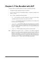
Chapter 1. Introduction
The Automated Validation Framework (AVF) plug-in is a SNAP plug-in designed as a
generic replacement for assessment and validation tools, such as the TRACE ATF and
AV Script. This section discusses the legacy tools and how AVF provides similar or
identical functionality.
1.1. Legacy Tools
AV Script
The Automated Validation Script (AV Script) is a Perl application that automates running
codes, generating plots, and computing figures-of-merit (FOM). It supports the RELAP5,
TRACE, and TRAC-B analysis codes and can also load data directly from ASCII and
NRC Databank files. AV Script is incorporated directly into the AVF plug-in. This
functionality has been made generic and pluggable so that additional codes can be
supported without any modifications to the AVF.
AcGrace and AptPlot
AcGrace and AptPlot are WYSIWYG, scriptable plotting applications with support for
analysis-code binary plot-files. The former is a legacy application written primarily
for UNIX and UNIX-like systems. Due to the difficulty of building and running the
application on Windows, AcGrace has been deprecated in favor of AptPlot, a functional
clone rewritten in Java. AptPlot can be run on any platform that supports a Java 6
compatible Runtime Environment.
The legacy AV Script could use either AcGrace or AptPlot to create plots and extract
data. Based on user inputs, AV Script generates AcGrace/AptPlot batch files that load,
plot, and export data. The AV Script component of the AVF utilizes AptPlot to perform
these tasks in much the same way as the legacy system. Unlike the original AV Script,
AcGrace cannot be used by the AVF, as the plug-in applies batch commands only
supported by AptPlot.
Note
AptPlot is not distributed with the AVF plug-in. Installation resources and
instructions can be found at www.aptplot.com.
ACAP
The Automated Code Assessment Program (ACAP) is described as "a tool to provide
quantitative comparisons between nuclear reactor systems (NRS) code results and
experimental measurements." AV Script runs use ACAP to generate figures of merit.
AV Script inputs define an ACAP config file (essentially a script without data) and the
data to compare. AV Script extracts the data from the source, fills out the config file with
these values, and runs ACAP with the complete script.
AVF Plug-in User's Manual
1
Introduction
The console version of this utility has been ported to Java so as to run on any platform
with a Java 5 compatible Runtime Environment. The Java port of ACAP is included with
the AVF distribution.
TRACE ATF
The TRACE Automated Testing Framework (ATF) is a collection of Perl scripts, input
files, and AV Script inputs used to analyze TRACE code versions. The framework
divides testing into three tiers of varying purpose: measuring consistency between code
versions (regression), code health (robustness), and code accuracy (assessment). Each of
these tiers are broken into several suites: related input groups.
Regression testing involves running a large number of inputs as a baseline, running
them again after some modification (such as an updated executable or a modified input
base), and comparing the differences. The TRACE ATF achieves this by using GNU
make to run the codes: make is chosen for its ability to run multiple inputs concurrently.
Once all the results have been arranged, a Perl script parses the results, diffs files, and
generates HTML reports that list the comparisons and catalog the diffs. This functionality
is supported in the AVF through a set of components that define regression suites, submit
options for regression and report jobs, and a generic report generator.
Robustness and Assessment compare results between code versions and data utilizing
AV Script along with several utility Perl applications. There is no distinction between
Robustness, Assessment, and standard AV Script runs in the AVF. This functionality
can be implemented by creating distinct AV Script components and selecting only the
scripts of interest at submit time.
1.2. SNAP and the AVF Plug-in
The Symbolic Nuclear Analysis Package (SNAP) consists of a suite of integrated
applications designed to simplify the process of performing thermal-hydraulic analysis.
SNAP provides a highly flexible framework for creating and editing input for engineering
analysis codes as well as extensive functionality for submitting, monitoring and
interacting with the analysis codes. The modular plug-in design of the software allows
functionality to be tailored to the specific requirements of each analysis code.
The Automated Validation Framework (AVF) is a SNAP plug-in designed to replace the
TRACE ATF and AV Script while providing a pluggable system for additional analysis
codes. The AVF plug-in uses a client/server model that should be familiar to many SNAP
users. Regression suites and AV Script definitions can be designed in the Model Editor
and submitted to a Calculation Server. The resulting jobs and their results can then be
observed with Job Status.
AVF Plug-in User's Manual
2
Chapter 2. Files Bundled with AVF
A number of files are installed with the AVF plug-in, including the following.
•
The plug-in JAR file required to use the AVF in SNAP.
•
A Java version of the ACAP command-line utility. A launcher is installed in the
SNAP bin folder.
•
An avf folder, containing the following folders:
•
bin - All executables and scripts employed by post-case and pre-figure
commands should be located here if not in the user's PATH.
•
plugins - AVF pluggable components are installed here. Several plug-ins are
included with the AVF distribution.
•
reportDefs - report definition XML files that determine how to generate
reports for a specific code type. Each definition is named after the plug-in ID of
the code it supports (TRACE.xml, RELAP.xml, etc.). Report definitions must
use the .xml extension.
•
templates - HTML templates used to generate regression reports.
Note
Modifying the resources in the avf directory is not officially supported.
However, it is possible to adjust the layout and contents of reports by modifying
definitions and templates. If you intend to do this, always back-up the avf
directory before making modifications, as errors in the XML and template files
can break AVF functionality. Note that updating the AVF plug-in overwrites
the contents of the avf folder, which will eliminate modifications.
AVF Plug-in User's Manual
3
Chapter 3. Model Options
The first Navigator element for any given AVF model is Model Options, which defines
properties and values that reach across the entire model. The following properties are
currently supported:
•
•
Name. The model name, which appears in the Navigator next to the MED file name.
Input Keywords. Described in the next section.
3.1. Input Keywords
Each AVF model may define a global set of input keywords, which assign a value of
true or false to an arbitrary keyword. The input keywords defined in the Model
Options define both the available keywords and their default values. Each keyword value
may be overridden by individual input models (see Section 4.1.1, “Input Models”) to
control input filtering (see Section 4.2, “Submitting Regression Jobs” and Section 5.4,
“Submitting Report Jobs”), case filtering (see Section 6.3, “Submitting AVScript Jobs”),
or control flow in a template job (see Section 7.1.2, “Templates”).
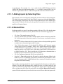
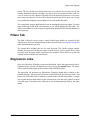
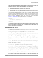
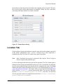
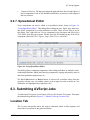
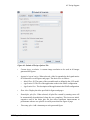
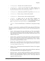
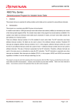
The Edit button in the Input Keywords editor opens the Edit Input Keywords dialog
(Figure 3.1, “Edit Input Keywords”).
Figure 3.1. Edit Input Keywords
The controls at the top of the window are used to add, remove, and reorder keywords.
Upon adding a keyword, the dialog prompts for its name, which may not be changed
once the keyword is created. The table in the center of the editor lists each keyword and
its default value, which can be edited as needed.
Pressing the OK button closes the dialog and sets the model's global keywords.
AVF Plug-in User's Manual
4
Chapter 4. Regression Support
Regression testing support is mainly focused around running a large number of inputs
from a single submit. Inputs are defined and organized in the model, their location is
defined at submit time, and the regression submit generates a job stream with steps for
each input model. By running multiple regression jobs over large input sets, variations
can be detailed in a generated report.
4.1. Regression Components
Regression components include input models, suites of input models, and sets of suites.
All components related to running regression jobs are located in the Regression category
in the Navigator.
4.1.1. Input Models
Input Model components denote code inputs for regression jobs. An input model
component is a file stub: the component represents a file without knowing that file's
absolute location on the machine. These stubs allow suites to refer to models without
specifying exactly where they are. During regression job submission, when the parent
location of the input models is known, each stub is used to complete the file's absolute
path.
Input Model components have the following noteworthy attributes:
•
•
•
•
•
•
File Name. The name of the file. Names must be unique for all models that share
a Location and Type. Models sharing a location should never have the same name
unless the input must be processed by multiple executables.
Location. Each Input Model may specify a folder-path relative to the parent folder
chosen at submit time. During the regression job process, this folder path is
preserved by creating the appropriate directories in the target folder.
Type. The type of input, discussed below.
Restart File. An optional restart reference to another input model. All restart models
are displayed in the Navigator with a modified label: if input model A restarts B, it
will be listed as "A > B".
Related Files. Described in Related Files.
Keyword Overrides. Described in Input Keyword Overrides.
The Type of an input model determines the executables used to run it. This value is
typically a SNAP plug-in ID. In some cases, this value may define which type of input
a model represents instead of the plug-in, as is the case with MELCOR models. When
the MELCOR plug-in is installed, an input model may be set as either a MELGEN or
MELCOR model. The type then determines which MELCOR plug-in executable is used
AVF Plug-in User's Manual
5
Regression Support
to run the input. For example, if a.inp is used as both a MELGEN input and then
a MELCOR input, two input models named a.inp would be created. One is set as a
MELGEN input and the other as a MELCOR input that restarts the MELGEN model.
4.1.1.1. Adding Inputs by Selecting Files
Input manuals can be created quickly through the selection of files on the local machine.
The right-click pop-up menu for the Input Models category provides the Select Files...
item, which opens a file browser. Any files selected in this browser will be added as new
input models. Within the file browser, the specified Type and Location values will be
applied to all imported inputs.
4.1.1.2. Related Files
Each input model may specify an arbitrary number of Related Files: files that the input
model depends on to function correctly. Related files have the following properties.
•
•
•
•
•
•
File Name. The complete name of the file.
Location. Similar to the Location of an input model, defines the relative path of the
file. Unlike input models, the relative nature of Location may vary based on the next
parameter.
Relative To. Defines whether the file's location is relative to the input folder specified
at submit time or the parent input model's location.
Type. Defines the purpose of the related file. Different AVF plug-ins support
various types of files. For example, TRACE AVF support allows the specification
of TRACE-PARCS coupled runs. For such a case, the Type of the coupled PARCS
input file must be set to PARCS Input, while other related PARCS files must be set
to PARCS Auxiliary File. This is used by the AVF plug-ins to determine how to
build the job stream elements used to process the input.
File Type. Indicates whether the file is a text or binary file.
Required. A True indicates that the file must be copied to the target folder for the
model to execute: if a submitted regression job cannot locate the related file, it does
not run the parent model. A False indicates that a missing file should not prevent
the parent model from running.
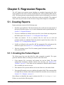
Input models containing related files may be expanded in the Navigator to display their
contents. Like any other Navigator node, related files may be created, removed, and
copied or pasted between input models. The right-click pop-up menu of an input model
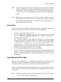
allows creating related files from files on the disk: selecting New Related File From File
opens a file browser that may be used to select one or more files to add to the input model.
AVF Plug-in User's Manual
6
Regression Support
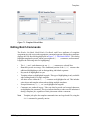
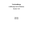
Figure 4.1. Creating a Related File from a File
4.1.1.3. Input Keyword Overrides
Each input model may override the values of the global input keywords (see Input
Keywords). There are two methods of defining overrides: the model-wide and inputspecific editors, both of which are described below.
Model-wide Keyword Assignment
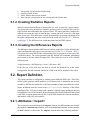
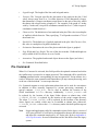
Selecting the Input Models category in the Navigator displays the Keyword Assignments
attribute in the Property View. The Edit button in the property editor displays the Assign
Input Keywords dialog shown below. This dialog is used to assign keyword overrides
for every input in the AVF model (see Input Keywords for more information on defining
keywords).
AVF Plug-in User's Manual
7
Regression Support
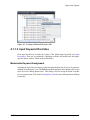
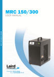
Figure 4.2. Keyword Assignment Dialog
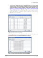
The central table displays a row for each input model and a column for every available
keyword. Highlighted values indicate that the input overrides the value of the particular
keyword: cells without highlighting correspond to inputs that use the default keyword
value. Setting a value to either true or false overrides the default. Overrides can be
removed from the selected inputs by pressing the Revert button in the upper-left corner
of the window.
AVF models often contain a large number of input models. The listed inputs can be
filtered with the text field in the upper right corner of the dialog. When the drop down to
the left is set to Filter, the filter text is treated as a basic file glob. Such a filter treats an
asterisk (*) as a wildcard: it matches any sequence of characters, including none. Only
inputs whose names match the filter will be displayed. When the drop down is set to
Regular Expression, a standard Java regular expression is used to filter the inputs. If the
regular expression is invalid it will be highlighted in red, and all inputs will be displayed.
Note
More information on Java regular expressions can be found at http://
java.sun.com/javase/6/docs/api/java/util/regex/Pattern.html.
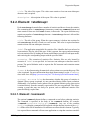
Specific Input Model Assignment
The Keyword Overrides property editor displays the Keyword Override Dialog, as shown
below. Once the values are set to the necessary values, pressing OK will set the overrides
for the input.
Note
Unlike the model-wide dialog, accepting changes made in this dialog will set
overrides for all currently available keywords.
AVF Plug-in User's Manual
8
Regression Support
Figure 4.3. Keyword Override Dialog
4.1.2. Suites and Suite Sets
Suite components are named lists of input models. When submitting a regression stream,
suites are selected to determine which inputs to run and their internal organization in the
generated job stream.
Suites may define Tokens that affect template jobs. Each token is a name=value pair
of strings that may be substituted into a template. Tokens are explained in more detail
in Section 7.1.1, “Input Models and Suites”.
Suites Sets are named lists of suits. Sets provide another layer of organization on top of
suites. Suite sets may be chosen in place of suites when submitting regression streams:
this has the same effect as selecting all suites represented by the requested sets. Sets have
no effect on the organization of regression job files.
Creating Suites From Keywords
Suites can be created from input keyword filters. The Suite category right-click pop-up
menu item Create From Keywords opens a Create Suites From Keywords dialog. The
Suite Name field defines the name of the new suite, and the table defines the filters that
dictate which models are added. Keywords are added to the filter via the Enable column.
Those inputs whose keyword value matches the Include Value of all enabled filters will
be added to the new suite.
See Input Keywords and Input Keyword Overrides for more information on keywords.
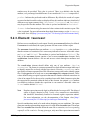
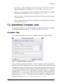
4.2. Submitting Regression Jobs
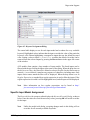
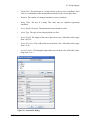
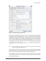
To submit a regression stream, select Submit Regression Job from the Tools menu.
This opens the submit dialog shown in Figure 4.4, “Submit Regression Dialog”. This
AVF Plug-in User's Manual
9
Regression Support
dialog is composed of three tabs. The Location tab contains information used to specify
information about the location at which the stream runs and where its inputs originate.
The Suites and Executables tab is used to specify which input models are submitted and
the applications used to run them. Finally, the Filters tab allows restricting which input
models are actually submitted.
Figure 4.4. Submit Regression Dialog
Location Tab
Platform allows selecting the location to run the regression stream from the platforms
specified in the SNAP configuration. Once a server is selected and a valid connection
is established, the Input Folder and Target Folder may be specified. The Select button
opens a dialog used for selecting a mounted folder on the server. With Input Folder, the
chosen directory is the location of the input files. The Target Folder specifies where the
stream will execute and store its results. Both of these values are specified as Calculation
Server URLs: note the calcserv:// protocol shown in the figure. All Calculation
Server URLs take the form calcserv://Platform/path/to/folder.
Note
Only Calculation Servers may be selected for the Platform. The AVF plug-in
does not support other platform types.
Name defines the name of the regression job: all stream tasks will execute in or under
a folder with this name. If the check next to the field is unselected, the name will be
generated based on the date.
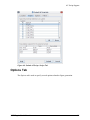
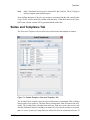
Suites and Executables Tab
The first table is used to select which suites are submitted. This is broken into two tabs:
Suites and Sets. The Suites tab allows selecting suites from the global list in the AVF
AVF Plug-in User's Manual
10
Regression Support
model. The Sets tab allows selecting from suite sets, with one caveat: suite sets are not
actually submitted. Instead, selecting a set selects all of its referenced suites, and vice
versa. A suite set is only shown as selected if all of its referenced suites are. If even one
suite in the set is inactive, the set will be shown as unselected. If two suite sets overlap,
it is possible that changing selected status of one will modify the other.
The second table assigns applications for use in running the regression inputs. For each
input model type found in the selected suites, a row will be displayed in this table. The
Application column is used to assign an application defined for the selected platform to
each input type.
Filters Tab
The table in this tab can be used to control which input models are included in the
regression job. Files are included based on their keyword value (see Input Keywords for
more information on keywords).
The central table includes one row for each keyword. The Enable column controls
whether the keyword will filter the inputs, and the Include Value column dicates what
keyword value the input model must have to be included. These values are saved and
restored between submits for convenience.
Regression Jobs
Once all of the above fields have been set to the desired values, the regression job can be
submitted to the selected Calculation Server by pressing the Submit button. Job Status
will be opened and navigate to the location of the submitted stream.
The regression job generates an Engineering Template stream that it submits to the
selected platform. The generated job stream is named after the specified run Name, and
has its root folder and relative location set based on the selected target folder. A single
step is generated per input model in each selected suite, with the step's relative location
set to the name of its parent suite followed by any location path specified by the input
model.
AVF Plug-in User's Manual
11
Chapter 5. Regression Reports
The AVF plug-in can generate reports detailing two completed regression jobs. Each
report compares a base code version to a modified code version (typically abbreviated as
mod). The report generator assumes that the modified version is a progressive revision of
the base version. In practice, this only effects how results are presented. The compared
codes can be any two codes or code versions so long as their outputs are comparable.
5.1. Creating Reports
Report generation consists of the following steps.
1.
Read the report definition. This file determines the overall structure and content of
the report, what files to parse, etc. For more information on the report definition, see
Section 5.2, “Report Definition”.
2.
If success conditions are defined in the report file, locate failed runs and generate
the failure report. See Section 5.1.1, “Creating the Failure Report”.
3.
Gather run statistics. To do so, statistics files for each run are read and
pertinent statistics are tabulated. Write the statistics reports from these values. See
Section 5.1.2, “Creating Statistics Reports”.
4.
If diffs are defined in the report file, diff the appropriate files and generate the
difference reports. See Section 5.1.3, “Creating the Differences Reports”.
5.
Write the summary report. This file contains general information and links to the
other generated files.
5.1.1. Creating the Failure Report
The failure report lists runs that failed for either compared executable. The report
generator identifies failures with the given checks in the order listed.
1.
If the statistics file is necessary and missing, the run has failed. The report
configuration determines whether statistics are necessary (see Section 5.2.3,
“Element: <success>”). If no other success conditions are defined and the statistics
file is available, the run is a success.
2.
If the statistics file is present and lists at least one fatal error, the run has failed.
3.
If no output file matches a success condition, the run has failed. This can mean either
no output files are found, or those that are found fail to meet the success criteria (see
Section 5.2.3, “Element: <success>”).
Once failures are identified, the report is written to the file FailureReport.html.
Failures are sorted in the following order:
AVF Plug-in User's Manual
12
Regression Reports
1.
2.
3.
4.
Unexpected: ran in base but failed in mod
Expected: failed in both
Fixed: failed in base but ran in mod
Misc: the run is not present for one version and failed in the other
5.1.2. Creating Statistics Reports
Statistics reports detail differences between the two code versions for a given statistic.
Any given run is only included in a statistics group's reports if a statistics file exists for
both versions and both contain the requested value. The report generator computes the
difference between the value in both the base version and mod version for each input
in the given suite. If the difference exceeds the threshold or percentage threshold set in
the report configuration, the value is included in the results (see Section 5.2.2, “Element:
<statGroup>”). The differences are sorted and printed out in HTML reports.
5.1.3. Creating the Differences Reports
The differences report tabulates diffs between various output files. Unless defined in the
report configuration, this report is not generated (see Section 5.2.4, “Element: <diff>”).
Any given run is only diffed if the corresponding files are present in at least one of the
version directories. The report generator runs the defined diff command, substituting
the location of the base and mod output files. The results are saved to a file with the
following path:
<report directory>/<diff directory>/<suite>/<file name>.diff
If the file size of the diff does not meet or exceed the threshold set in the report
configuration, the diff is deleted. Otherwise, a link to the diff is included in the report.
5.2. Report Definition
The report generator is configured by reading report definition XML files. These files
tell the report generator which statistics are of interest, how to determine run success,
whether to diff files and which files to diff, and a number of other miscellaneous values.
Report definitions must be stored in the avf/reportDefs directory of the SNAP
installation. The AVF plug-in ships with a number of default report definitions that can
be modified or serve as an example. Report definition files must be both well-formed and
valid XML, or report generation will fail. As in all XML documents, elements, attributes,
and attribute values are case-sensitive.
5.2.1. Attributes: <report>
The root tag of a report definition is the report element. Its child elements may include
any number of statGroup elements, zero or one success elements, and any number
of diff elements, in that order. The report element allows the following attributes.
AVF Plug-in User's Manual
13
Regression Reports
title - The title of the report. This value must contain at least one non-whitespace
character and is required.
description - A description of the report. This value is optional.
5.2.2. Element: <statGroup>
Each statGroup element defines a number of statistics and how to locate the statistics
files containing them. A statGroup element may contain one command element and
must contain at least one child stat element, in that order. The report definition may
contain any number of statGroup elements. A statGroup element is allowed the
following attributes.
title - The title of the group. When the report summary is broken into sections for
each statGroup, the title is listed over each section. This value is required and must
contain at least one non-whitespace character.
label - The application output label for statistics files. Identifies the keyword used to
locate statistics files for jobs of this type. If this is present, the report generator attempts
to locate statistics files by loading the stream task defintion created for each input model,
and retrieving the corresponding output with the specified label.
extension - The extension of statistics files. Statistics files are only located by
extension if label is not specified. At least one non-whitespace character must be
present. The period delimiter used to separate the file basename and extension cannot
be included.
format - A Java format-string for numerical values written to a report in this group. This
value is optional. For more information about legal format-strings, see the Formatter
class in the Java API [http://java.sun.com/j2se/1.5.0/docs/api/java/util/Formatter.html].
optional - a true or false that determines whether this group of statistics is
optional. When a group is optional, it is not considered during failure report evaluation.
Additionally, if no statistics can be gathered for an optional statistics group, that section
is omitted entirely from the summary report and its files are not generated. This allows
creating a group that may not always be present, such as additional statistics files
generated during coupled runs.
5.2.2.1. Element: <command>
The optional command element defines a command to run before gathering statistics.
The command is specified in the body of the command element; for example:
<command>createStatistics.pl</command>. Any use of the construct
%avf_bin within the command will be replaced with the absolute location of the avf/
bin folder of the SNAP installation. No attributes are allowed in this element. Typically,
it is expected that a command will run some application or script that examines a model's
AVF Plug-in User's Manual
14
Regression Reports
output files and generate additional statistics. When the report generator executes the
command, it provides it with the following arguments in the order listed:
1.
the absolute location where a regression input was executed
2.
the prefix of the input model (the name of the input model without a file extension)
This information should be sufficient for any utility to locate the outputs of interest
and generate results. For the report generator to tabulate these results, the utility should
generate a statistics file at the provided location with the given prefix and the extension
listed in the parent statGroup element. The statistics file format is detailed in
Section 5.3, “Statistics File”, but a general example is provided below.
<?xml version="1.0"?>
<statistics>
<stat name="first value" value="1.0"/>
<stat name="second value" value="2.0"/>
...
</statistics>
The executed command is expected to run until it completes writing the statistics report,
then exit immediately. It should not spawn a background process that generates the
statistics value and then exit prematurely.
5.2.2.2. Element: <stat>
The stat empty element defines a statistic used to generate a report. At least one stat
element must be defined in each statGroup. It has the following attributes.
name - The name of statistics included in the report. Values must contain at least one
non-whitespace character. This attribute is required.
file - The name of the HTML file created for the report. For portability, this value
has some restrictions. Values must begin with at least one letter or number. Afterwards,
the file name may consist of any number of letters, numbers, and periods. This attribute
is required.
title - The title of the report. Values must contain at least one non-whitespace
character. This attribute is required.
description - A description of the report. This attribute is optional.
threshold - A difference threshold for statistics. The magnitude of the difference
between statistics must exceed this value to be considered for the report. A difference
within this threshold may still be significant if a factor is specified (see below). Only
non-negative real numbers may be provided. This value is optional and defaults to "0"
if unspecified.
factor - A percentage of the base value that differences must exceed to be considered
for the report. This percentage is specified with 1.0 as 100%. Only non-negative real
AVF Plug-in User's Manual
15
Regression Reports
numbers may be provided. This value is optional. There is no default value for this
attribute, so a percentage-based difference is not considered if factor is unspecified.
prefer - Indicates the preferred trend in differences. By default, the results of a report
are sorted so that favorable results are displayed first; this attribute indicates what kind of
differences are improvements. Only "decrease", "increase", and "neither"
may be specified for this attribute. This value is optional and defaults to "neither".
format - A Java format-string for numerical values written in this statistics report. This
value is optional. For more information about legal format-strings, see the Formatter
class in the Java API [http://java.sun.com/j2se/1.5.0/docs/api/java/util/Formatter.html].
5.2.3. Element: <success>
Defines success conditions for code output. Exactly one success block may be defined.
If success is not defined, the report generator will not create a failure report.
The success element defines one attribute: stats. A positive stats value indicates
that the existence of a statistics file is a necessary indicator of success. Allowable values
are "true" and "false". This attribute is optional and defaults to "false". The
body of the success element consists of one or more condition elements. Each
condition element defines a file-set and success criteria through its attributes and
children.
The condition element should define only one of two attribute: label or
extensions. The former is a comma-separated list of task definition output labels used
to identify output files to check with the type criteria. Likewise, extensions can be
specified as a comma-separated list of file extensions (sans period) used to identify output
files. Each type has in its body one or more message and/or regex elements. These
values define a string or regular expression that must be found or matched somewhere in
a line of an output file for the run to be considered successful. Both elements require that
the expression be contained within the body of the element. An optional case attribute
is available to indicate whether the expression is case-sensitive: allowable values are
"true" and the default "false".
Note
Regular expressions must be legal as defined in the Java regex API. The allowed
syntax is largely identical to Perl 5 (only a few constructs are unavailable),
and should be immediately familiar to seasoned regular expression authors.
For more information, see the documentation of the Pattern class [http://
java.sun.com/j2se/1.5.0/docs/api/java/util/regex/Pattern.html].
Special considerations need to be made when designing success conditions. The report
generator runs through matching outputs once for each defined condition. This means
that if two condition elements define the same file or extension, each corresponding
output file will be read twice. For any given type, only one of the expressions must match
AVF Plug-in User's Manual
16
Regression Reports
for the run to be considered successful, allowing parallel types to be collapsed into a
single element. Consider the following example:
A code creates two output files for any given run: one with the extension .info and the
other with .out. The message "done" indicates success in both types of files. The regular
expression "^complete:" also indicates success if found in .info files. The following
conditions block would correctly locate successful runs.
<success>
<condition extensions="out,info">
<message>done</message>
</condition>
<condition extensions="info">
<regex>^complete:</regex>
</condition>
</success>
As pointed out earlier, this will cause the report generator to read .info files twice.
After collapsing the two types, the redundant reads are eliminated.
<success>
<condition extensions="out,info">
<message>done</message>
<regex>^complete:</regex>
</condition>
</success>
Unfortunately, this could still lead to problems. If the regular expression matches a line
in .out files that does not indicate success, the report generator can produce false
positives. The following eliminates any ambiguity.
<success>
<condition extensions="info">
<message>done</message>
<regex>^complete:</regex>
</condition>
<condition extensions="out">
<message>done</message>
</condition>
</success>
Each file is now read exactly once with only those success-conditions that apply.
5.2.4. Element: <diff>
Indicates that a diff utility should be run on various code outputs. When present, links
to the diffed files are tabulated in a differences report. The report definition may define
any number of diff elements: a section will be created in the summary report for each.
The diff tag has the following attributes:
title - The title of the diff report. This value defaults to "Diff Report" and must
have at least one non-whitespace character if modified. This value should be unique
between diff elements.
file - The name of the file that stores the diff report. This value defaults to
"DiffReport.html" and must have at least one non-whitespace character if
modified. This value should be unique between diff elements.
AVF Plug-in User's Manual
17
Regression Reports
description - An optional description of the diff report.
location - The location to store the file diffs. This value defaults to "diffs" and
must have at least one non-whitespace character if modified. This value should be unique
between diff elements.
program - The differencing application to use. For Windows users, the default value
"diff" indicates that the included GNU diff command line utility should be used. To
use the included diff utility directly, use the value %gnudiff. The custom APT diff
utility, which allows specifying an exclusion list to ignore certain parts of the diffed
documents, can be referenced with the value %aptdiff. Any use of the construct
%avf_bin will be replaced by the absolute location of the avf/bin folder in the
SNAP installation, while %cafean_home will be replaced by the location of the SNAP
installation itself.
command - The diff command arguments. This value supports two symbolic constructs:
%base and %mod. These two values are replaced with the path of the diffed files from
the base and mod code output. The attribute value must include both %base and %mod
at least once. If undefined, the value defaults to "%base %mod".
label - The task definition output labels used to locate files to diff in a comma-separated
list.
extensions - The extensions of files to diff, sans period, in a comma-separated list.
This value must contain at least one non-whitespace character. If undefined, it defaults
to "out".
threshold - The size in bytes that a diff must meet or exceed before included in the
report. This value must be a non-negative integer. If undefined, it defaults to "20480"
(20kB). To include every diffed file, set threshold to "0".
5.3. Statistics File
The statistics file format stores named numerical values and error descriptions in XML.
Like report configuration files, the XML contents must be both well-formed and valid.
Any code that outputs statistics files in this format can be used with the report generator.
The statistics file has only a few elements: a root statistics tag, a block of stat
elements, and an optional block of error elements. The statistics element serves
only as the root tag; no attributes are allowed. Each stat defines a value through two
attributes: name and value. The constraints on these attributes are straightforward:
both are required, name must contain at least one non-whitespace character, each name
must be unique within the file, and value must be a real number.
Statistics files may also define any number of empty error elements after the stat
block. The following attributes are available for error.
AVF Plug-in User's Manual
18
Regression Reports
type - The type of error. Allowable values are "input" and "runtime". This value
is required.
reason - Specifies a short description of the error. Values must have at least one nonwhitespace character. This value is required.
fatal - Indicates whether the error is fatal, causing the executable to terminate early.
Allowable values are "true" and "false". This value is optional and has no default.
componentType - If the error can be directly associated with a component, that
component's type is specified here. Values must have at least one non-whitespace
character. This value is optional and has no default.
componentID - If the error can be directly associated with a component, that
component's identity is specified here. Values must have at least one non-whitespace
character. Values must have at least one non-whitespace character. This value is optional
and has no default.
lineNumber - This attribute can be utilized to specify a specific line in the input file
that caused the error. Only positive integers may be specified. This value is optional and
has no default.
time - Allows specifying the simulated time when the error occurred. Only real numbers
may be provided. This value is optional and has no default.
Below is an example of the statistics file syntax.
<?xml version="1.0"?>
<statistics>
<stat name="cpu time" value="10.0" />
<error type="input"
lineNumber="42"
reason="first column must be greater than 0"
fatal="false"
componentType="pipe"
componentID="11" />
<error type="runtime"
time="10.5"
reason="divide by 0"
fatal="true"
componentType="pipe"
componentID="11" />
</statistics>
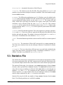
5.4. Submitting Report Jobs
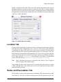
To submit a report job, select Submit Report Job from the Tools menu. This opens the
submit dialog shown in Figure 5.1, “Submit Report Dialog”. This dialog is composed
of three tabs. The Location tab contains information used to specify information about
AVF Plug-in User's Manual
19
Regression Reports
the location at which the job runs and where the compared jobs are located. The Suites
tab is used to specify which input models are submitted. Finally, the Filters tab allows
restricting which input models are actually examined.
Figure 5.1. Submit Report Dialog
Location Tab
Platform allows selecting the platform to run the report job from the platforms specified
in the SNAP configuration. Once a server is selected and a valid connection is
established, the Base Job, Mod Job, and Location may be specified.
Note
Only Calculation Servers may be selected for the Platform. The AVF plug-in
does not support other platform types.
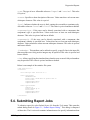
Location is the target folder where the report will be generated. The Select button opens a
dialog used for selecting a mounted folder on the server. Base Job and Mod Job define the
two previously submitted regression jobs that will be compared in the report. The Select
button to the right of each will open the Select Regression Job dialog shown in Figure 5.2,
“Select Regression Job Dialog”. All of these values are specified as Calculation Server
URLs: note the calcserv:// protocol shown in the figure. The Location URLs take
the form calcserv://Platform/path/to/folder, while Base Job and Mod
Job also specify the name of a completed run in the form calcserv://Platform/
path/to/RegressionJobName.
AVF Plug-in User's Manual
20
Regression Reports
Figure 5.2. Select Regression Job Dialog
Name defines the name of the report job. Any resource associated with this job created
in the Target Folder will be named with this label. If the check next to the field is not
selected, the name will be generated based on the date.
Suites Tab
The Included Suites section displays the suites that are included in both selected
regression jobs. Any or all of these suites can be selected to be included in the report.
Filters Tab
The table in this tab can be used to control which input models are included in the report
job. Files are included based on their keyword value (see Input Keywords for more
information on keywords).
The central table includes one row for each keyword. The Enable column controls
whether the keyword will filter the inputs, and the Include Value column dicates what
value the input model must have for the keyword to be included. These values are saved
and restored between submits for convenience.
Submitting the Report Job
Once all of the above fields have been set, the report job can be sent to the Calculation
Server by pressing the Submit button. This will add the report run to the server's job
queue. This process compares the statistics, failures, resulting output, etc. and creates an
HTML report displaying the results. For more information on how reports are defined,
see Section 5.2, “Report Definition”.
AVF Plug-in User's Manual
21
Chapter 6. AV Script Support
AV Script jobs allow the automation of running cases, generating figures from the results,
and computing figures-of-merit.
The AVF support for AV Script is now a front-end for generating complex Engineering
Template streams. The functionality of the legacy AV Script system now be reproduced
by standard Job Stream components via the AptPlot and ACAP steps bundled with
SNAP. To that end, the AVF supports components that largely mirror the legacy AV
Script inputs. These components are then translated directly into Engineering Template
models and, when submitted, run as a batch of job streams.
6.1. Changes From Legacy AVScript
For those experienced with the legacy AVScript application, it is important to clearly
identify which input values are not necessary or have different semantics in the new
system. This section highlights changes to the way scripts are defined. New users can
skip this section entirely.
Most values in the path definitions are unneeded. The paths definition file indicates
the paths to a number of required applications and resources. Several of these values
are defined in the SNAP configuration, such as the location of AptPlot and the
demultiplexers. For resources bundled with the AVF plug-in, such as ACAP, the location
is already known. No equivalent to topdir is necessary: the locations of inputs and outputs
have been decoupled and are specified when the script is submitted. Applications are also
defined at submit time (see Section 6.3, “Submitting AVScript Jobs”). When importing
legacy AVScript inputs, code versions are parsed into Executable stubs with the indicated
name and type.
All Location properties define input locations in Calculation Server path syntax. When
submitting AVScripts, a mounted folder on a Calculation Server is selected as an input
location. On the server, AVF looks for all input files underneath this input folder. As
an example, a Case input file a.inp is located at C:\trunk\Assessment\WALL\inputs. The
folder C:\trunk\ is mounted on this server with the name TRUNK. During submit, the
user selects /TRUNK/Assessment as the input folder. For a case to correctly locate this
file, its File Name must be set to a.inp and its Location set to WALL/inputs. Note the
lack of prefix and the use of the slash character (/) as a folder separator. Constructs such
as ../ cannot be used to reach a directory outside the selected input folder. The Location
field is kept separate from the file name to facilitate multi-edit.
Case files that might not exist before running a post-case or pre-figure command are not
prefixed with an ampersand. Instead, set the Check Existence property to false.
Case file names and ACAP config-file names must include the file extension. These are
no longer assumed, except when importing legacy AVScript inputs.
AVF Plug-in User's Manual
22
AV Script Support
Legend coordinates should never be prefixed by a 'W'. By doing so, the legacy AVScript
marked the legend coordinates as world-coordinates on an AptPlot graph. Instead, set
the figure's Legend Coordinate Type value to World.
Annotations are now defined as a component of a figure. Each figure has an Annotations
property. The editor launches a dialog that can be used to add, remove, and edit
annotations. This naturally represents the way annotations related to figures in the legacy
input format.
Ellipse annotations are no longer defined in the form: Xcenter, Ycenter, Width, Height.
Instead, they follow the standard convention of Xmin, Ymin, Xmax, Ymax. When importing
legacy AV Scripts, the coordinates of an ellipse annotation are automatically converted
to the standard form.
Data definition expressions should not be prefixed by an equals sign. Instead, set the X
Variable Type or Y Variable Type value to Expression.
Data channel names in expressions must be surrounded by curly braces: {}. This
eliminates error-prone channel-name checks that fail for various channel names in
Databank files.
Variables in axial data definitions no longer use ZZ or ZZZ to indicate the mesh index
segment. Instead, they use the %2N, %3N, etc. format defined for AptPlot's built-in axial
plot functionality. The old format is automatically converted to the new format on import.
Figure and page names must be unique between both figure and page definitions. Files
generated for figures and pages (AptPlot batch files, images, etc.) are created in common
directories. If a figure and a page in the AVScript component share a common name, the
figure files will be overwritten, and unexpected errors may arise.
Figures and pages no longer have a file location value. Instead, generated files are
automatically sorted into a predefined directory structure.
6.2. AV Script Components
The AV Script category contains all components related to AV Script streams. It contains
two child categories: Executables and Scripts. Executable components define codeversion stubs mapped to an application at submit time. Each Script component is
composed of cases, figures, and data traces that define how to run inputs and generate
plots. Scripts may be expanded in the navigator to display a number of sub-categories,
all of which support copy and paste.
AVF Plug-in User's Manual
23
AV Script Support
Figure 6.1. AV Script Components in the Navigator and Property View
6.2.1. Executables
Executable components specify named code executables for AVScript runs. Similar to
input model components, each executable is a stub that takes the place of an executable
defined at submit time. This allows AVScript components to reference specific code
versions without knowing where the executable is located.
Executable components have the following noteworthy attributes:
•
•
Executable Name. The name of the executable. Each name must be unique among
executables.
Executable Type. The type of executable. This value must be the name of an AVF
code-support plug-in.
6.2.2. Cases
Cases represent code inputs and data sources. A case component defines an input or
data file, its type, a code version used to run the input (if appropriate), and any restart
information.
Cases have the following properties:
•
Case Name. The ID of this case. Each Case Name should be unique among cases
in the parent Script component.
•
File Name. The complete name of the file referenced by this case.
AVF Plug-in User's Manual
24
AV Script Support
•
Location. The Calculation Server path where the input or data file is located. This
location should use the slash character (/) as a folder separator. Do not prefix the
path with separators. Constructs such as ../ will not work here.
•
Check Existence. This should only be set to false if a post-case or pre-figure
command is going to generate the file.
•
Case Type. The type of this case. The type determines what codes are used to process
inputs, how data is extracted from files, etc.. The editor for this value allows selecting
from the supported case types found on the client machine. If the AVF installation
where the script will be submitted contains support for additional codes, their types
can be entered manually.
Several case types for data files are always supported. These include the following.
• ASCII Data. A text file with values in space-delimited columns.
• DATABANK Data. An NRC Databank binary data file.
•
Version. The executable used to run this case. This is not displayed for known datafile types.
•
Restart File Name. If activated, this field specifies the optional restart case. This is
not displayed for known data-file types.
•
Post Command. Described below.
•
Case Files. Described below.
•
Keyword Overrides. Described below.
Post Command
When Post Command is activated, this field specifies the optional command run
immediately following execution of the case. This command will be specified as a Post
Execution command on the corresponding job step in exported AV Script streams.
As a result, it follows the same semantics and constraints as job step custom processing,
such as the use of the backslash '/' as an escape character.
Post Command supports several replacement tokens that can be used for convenience
in addition to those normally supported by custom processing commands. A
special construct, ${AVF_BIN}, can be used to indicate the location of the
SNAP installation's avf/bin directory. Additionally, ${INPUT_FOLDER} will
be replaced by the location of the Input Folder chosen at submit time, while
${TARGET_FOLDER} is replaced by the location of the script's output directory.
The token ${FIGURE_FOLDER} will be replaced by the location of the directory
where figures are created, which may be overridden at submit time. Otherwise,
${FIGURE_FOLDER} refers to the Plots directory under which all AptPlot steps are
executed.
AVF Plug-in User's Manual
25
AV Script Support
Note
Scripts and applications called by commands written for the legacy version of
AVF (prior to SNAP 2.0) will have to be adjusted for the new directory structure
and input file constraints employed by AV Script jobs. Refer to Appendix A,
AV Script Execution for more information on how this differs from the legacy
system.
Note
Whenever any case or figure in an AV Script specifies a custom command,
the generated stream will run with Linear Execution enabled. This is necessary
to ensure that custom commands are executed before any subsequent cases or
figures that depend on the results.
Case Files
Each case may specify an arbitrary number of Case Files: files that the input model
depends on to function correctly. Case files have the following properties.
•
•
•
•
•
File Name. The complete name of the file.
Location. Similar to the Location of a the parent case, this defines the relative path
of the file. Unlike cases and input models, this path is relative to the parent case
file instead of the input folder.
Type. Defines the purpose of the related file. Different AVF plug-ins support
various types of files. For example, TRACE AVF support allows the specification
of TRACE-PARCS coupled runs. For such a case, the Type of the coupled PARCS
input file must be set to PARCS Input, while other related PARCS files must be set
to PARCS Auxiliary File. This is used by the AVF plug-ins to determine how to
build the job stream elements used to process the input.
File Type. Indicates whether the file is a text or binary file.
Required. A True indicates that the file must be copied to the target folder for the
model to execute: if a script job cannot locate the related file, it does not run the
parent case. A False indicates that a missing file should not prevent the parent case
from running.
Input Keyword Overrides
Each case may override the values of the global input keywords (see Input Keywords).
There are two methods of defining overrides: the spreadsheet editor (see Section 6.2.7,
“Spreadsheet Editor”), and the case-specific editor, which is described below.
The Keyword Overrides property editor displays the Keyword Override Dialog, as shown
below. Once the values are set to the necessary values, pressing OK will set the overrides
for the case.
Note
Unlike the spreadsheet editor, accepting changes made in this dialog will set
overrides for all currently available keywords.
AVF Plug-in User's Manual
26
AV Script Support
Figure 6.2. Keyword Override Dialog
6.2.3. Figures and Annotations
Figure components define the look of a graph, including the graph's title, subtitle,
position on the plot, etc.. Figures may optionally contain annotations: custom lines,
boxes, ellipses, and text rendered on the plot.
The following properties are available for figure components:
•
Figure Name. The figure ID. Each name should be unique among figures and pages
in the parent Script component.
•
Title Text and Subtitle Text. The optional title and subtitle drawn over the graph.
•
X Axis Label and Y Axis Label. Denotes the labels drawn along the X and Y axes.
•
Scaling Type. Determines whether the X and Y axes are scaled linearly or
logarithmically.
•
X Axis Boundaries and Y Axis Boundaries. Determines if the X and Y axes are scaled
automatically or explicitly. Automatically scaled graphs adjust their X and Y bounds
to display all data values. Explicit boundaries are defined below.
•
Axis Bounds. Defines the minimum and maximum values displayed by the figure.
This property is only enabled if at least one of X Axis Boundaries or Y Axis
Boundaries is set to Explicit.
•
Tick Marks. Sets the major and minor tick intervals along the X and Y axes.
•
Legend X Coordinate and Legend Y Coordinate. The location of the legend's upperleft corner.
•
Legend Coordinate Type. Determines if the coordinate described above is a
Viewport coordinate or a World coordinate.
AVF Plug-in User's Manual
27
AV Script Support
•
Legend Length. The length of the line used in legend entries.
•
Viewport. The Viewport specifies the placement of the graph on the plot. Valid
values always range from 0 to 1 in either direction. If one dimension is longer,
that dimension's viewport coordinates extend from 0 to the ratio of the sides, which
the shorter side always having a length of 1. For example, if the graph is 3 inches
wide by 2 inches tall, viewport X coordinates extend from 0 to 1.5, and viewport Y
coordinates extend from 0 to 1.
•
Character Size. The default size of text rendered in the plot. This value is a multiplier
of AptPlot's default font size. Thus, specifying .75 will produce text that is 75% of
the normal size.
•
Symbol Size. The default size of symbols rendered in the plot. Like Character Size,
this value is a multiplier of AptPlot's default size.
•
Orientation. Determines the size of the plot on which the figure is graphed.
•
Page Width and Page Height. The size of the plot in inches. Width and height are
only available if the Orientation is set to Custom.
•
Annotations. The graphical and textual objects drawn on the figure (see below).
•
Pre Command. Described below.
Pre Command
When Pre Command is activated, this field specifies the optional command run before
the AptPlot step is executed or its inputs processed. This command will be specified as
a Setup command on the corresponding job step in exported AV Script streams. As a
result, it follows the same semantics and constraints as job step custom processing, such
as the use of the backslash '/' as an escape character.
Pre Command supports several replacement tokens that can be used for convenience
in addition to those normally supported by custom processing commands. A
special construct, ${AVF_BIN}, can be used to indicate the location of the
SNAP installation's avf/bin directory. Additionally, ${INPUT_FOLDER} will
be replaced by the location of the Input Folder chosen at submit time, while
${TARGET_FOLDER} is replaced by the location of the script's output directory.
The token ${FIGURE_FOLDER} will be replaced by the location of the directory
where figures are created, which may be overridden at submit time. Otherwise,
${FIGURE_FOLDER} refers to the Plots directory under which all AptPlot steps are
executed.
Note
Scripts and applications called by commands written for the legacy version of
AVF (prior to SNAP 2.0) will have to be adjusted for the new directory structure
and input file constraints employed by AV Script jobs. Refer to Appendix A,
AV Script Execution for more information on how this differs from the legacy
system.
AVF Plug-in User's Manual
28
AV Script Support
Note
Whenever any case or figure in an AV Script specifies a custom command,
the generated stream will run with Linear Execution enabled. This is necessary
to ensure that custom commands are executed before any subsequent cases or
figures that depend on the results.
Figure Templates
AVF supports exporting a Figure's properties as a template. Such templates can then
be imported with only selected values substituted into the edited figure's properties. To
export a template, select a figure in the Navigator. In the property view, select the Export
Template button in the Figure Template property editor. Select the location to save the
file and press Save. To import a template, select the Import Template button from the
same editor, select the template, and press Open. A dialog will be displayed asking which
properties to import, and showing the value of each property in the template. Select the
desired properties and press the OK button to import the values.
Annotations
To edit a figure's annotations, select the Edit button from its Annotations property.
This displays the Edit Annotations dialog as shown in Figure 6.3, “Annotation Dialog”.
With this dialog, annotations can be created, removed, and edited. Annotations have the
following properties:
•
Annotation Name. The ID of the annotation. Each name should be unique among
annotations in the figure.
•
Object Type. The type of the annotation: box, ellipse, string of text, or line.
•
Color. The color of the annotation.
•
Location. The placement of the annotation in world coordinates. Box, ellipses, and
lines use minimum and maximum coordinates to specify the absolute placement of
the shape. Strings are placed by a single coordinate that places the string based on
the Justification. All locations are specified in world coordinates, which are relative
to the values displayed on the graph.
•
Line Style. The style of the line: solid, dotted, dashed, or a combination. This value
is only available for boxes, ellipses, and lines.
•
Line Width. The width of the line, from 0 to 20. This value is only available for
boxes, ellipses, and lines.
•
Fill Color. The color used to fill a box or ellipse.
•
Fill Pattern. The pattern used to fill a box or ellipse.
•
Font. The font used to render a string.
•
Character Size. The character size used to render a string. This value should range
from 0 to 1000, where 100 is 100% of the default character size.
AVF Plug-in User's Manual
29
AV Script Support
•
Justification. The placement of a string relative to the Location coordinate. Each
value is a combination of horizontal placement followed by vertical placement.
•
Rotation. The rotation of a string around the Location coordinate.
•
String Value. The text of a string. This value may use AptPlot's typesetting
constructs.
•
Arrow Heads Placement. The placement of arrow heads on a line.
•
Arrow Type. The type of arrow heads placed on a line.
•
Arrow Length. The length of the arrows placed on a line. Allowable values range
from -10 to 10.
•
Arrow d/L Factor. The width of the arrow head on a line. Allowable values range
from 0 to 10.
•
Arrow l/L Factor. The triangular shape of the arrow head on a line. Allowable values
range from -1 to 1.
Figure 6.3. Annotation Dialog
AVF Plug-in User's Manual
30
AV Script Support
6.2.4. Data Traces
Data traces define a data set in a graph. They specify the case from which the data
originates, the figure upon which the trace is plotted, the channel or complex expression
that defines the data, the appearance of the line, etc.. Data Trace properties are described
below.
In the General attribute group.
•
Data Name. The ID of this data trace. Each name should be unique among data
definitions in the AVScript component.
•
Case. Where the plot data originates. Each data trace must have a valid case
reference.
•
Figure. Where the data is plotted. Each data trace must have a valid figure reference.
•
Plot Type. The type of plot represented by this data trace. The available options
are described below. Unless otherwise noted, any two data traces referencing a
particular figure must have identical plot types.
• Time. A simple time-history plot. Only Y Variable may specify data in the trace.
The X Variable is either assumed or taken automatically from the appropriate
source (such as the time channel in a binary plot file).
• Time Point. A single point from a time-history plot. Only Y Variable may
specify data in the trace. These plots must also specify the Time value (not to
be confused with the Time plot type). This indicates which point in the data set
should be extracted and plotted. Time Point data traces may reside on the same
figure as Time plots.
• Parametric. Similar to Time, but X Variable is also defined.
• Parametric Point. Similar to Time Point, but X Variable is also defined.
Parametric Point data traces may reside on the same figure as Parametric plots.
• Axial. An axial profile plot. Only Y Variable is specified, but it allows a special
construct for substituting incremental channels (described below). Axial plots
cannot be used with Databank cases, and do not allow expressions.
•
X Variable, X Variable Type, Y Variable, and Y Variable Type. The variable to be
plotted on the X or Y axis and whether that value is an expression or a channel. This
value can be a channel name, data file column index, or complex channel expression.
For ASCII Data, specify the column in the data file to use, with column indexes
starting at 1. Other types may use either a channel name or a complex expression.
For channel variables, enter the name of the channel. The property editor allows
selecting channels from a completed job on a Calculation Server. Only those jobs
that match the referenced case's Case Type will be displayed.
Expressions may be any valid AptPlot Equation Interpreter expression, with one
caveat: channel names must be surrounded by curly braces: {}. This tells AVF
exactly where the channel name begins and ends so that it can substitute the
AVF Plug-in User's Manual
31
AV Script Support
appropriate file-prefix in AptPlot expressions. If a channel name uses curly braces
or backslashes, they can be escaped with a backslash; { becomes \{, } becomes
\}, and \ becomes \\.
Axial data traces use the construct %2N, %3N, etc. to indicate the portion of the
channel name substituted with axial mesh indexes. The integer in the construct
determines how many digits must be present in channel names for indexes less than
the ceiling index.
•
Legend String. Optional text to be used in the figure's legend for this data trace. If
left inactive, the legend value will be automatically generated.
•
Units. If the case type supports it, determines whether values are converted to SI or
British units. This value has no effect on ASCII Data values.
•
X Shift. Shifts all values along the X axis by this value.
•
Y Shift. Shifts all values along the Y axis by this value.
•
Slope Factor. Multiplies all Y values by this value after the shift.
•
Time. The transient time for which the axial plot or time point information is to be
extracted. For Time Point and Parametric Point traces, the time may be set to a value
less than or equal to -1e9 to specify that the first available time step should be used,
or greater than or equal to 1e9 to indicate the last.
In the Line Properties attribute group.
•
Symbol. The type of symbol centered over data points in the figure.
•
Symbol Fill. Whether the symbols are filled or outlines. This parameter is only
enabled if Symbol is set to a value other than None.
•
Symbol Skip. How many data points are skipped between rendered symbols. This
parameter is only enabled if Symbol is set to a value other than None.
•
Line Style. The type of line drawn between points in the data set.
•
Line Color. The color of the line drawn between points in the data set.
•
Line Width. The width of the line drawn between points in the data set.
In the Axial Plot Definitions attribute group.
•
Fine-Mesh Elevations. Determines how the axial trace is created for data channels
with fine-mesh elevation data, such as rftn in TRACE runs. When set to
Automatic, every elevation value found at the provided time will be plotted. When
set to Explicit, the trace will be restricted to the elevations specified in the Axial
Locations property.
Note
This property is only available for channels with fine-mesh elevation data.
AVF Plug-in User's Manual
32
AV Script Support
•
Axial Locations. Defines the axial or z-direction locations for a series of mesh
locations in a single component along the direction of flow for the data channel being
plotted (specified by Y Variable). Editing the property displays the dialog shown
in Figure 6.4, “Edit Axial Locations Dialog” and Figure 6.5, “Edit Axial Locations
Dialog with Fine Mesh Data”. This dialog can be used to add and remove axial
locations, and enable and set an optional axial index override. In addition, the Index
Offset (or Start Index) is specified here, defining the first index used by locations
that do not override their index.
Figure 6.4. Edit Axial Locations Dialog
When setting explicit elevations for channels with fine mesh data, the dialog removes
the index fields, as they are determined automatically by AptPlot.
Figure 6.5. Edit Axial Locations Dialog with Fine Mesh Data
AVF Plug-in User's Manual
33
AV Script Support
6.2.5. Pages
Pages allow displaying several figures on a single plot. Each page has the following
properties:
•
Page Name. The page ID. Each name should be unique among pages and figures in
the parent AVScript component.
•
Figures. The figures organized by this page definition. Each page should have at
least one valid figure reference. The number of figures should match the product of
the Row Count and Column Count properties.
•
Row Count and Column Count. The number of rows and columns that the referenced
figures are organized into.
•
Override Title and Override Subtitle. Optional overridden title and subtitle for the
organized figures. When activated, only this title and/or subtitle will be displayed;
all other figure titles and subtitles will be discarded.
•
Margin. The margin between the edges of the plot and the arranged figures, specified
in viewport units.
•
Column Gap and Row Gap. The margin between columns and rows in the arranged
figures, specified in viewport units.
•
Orientation. The size of the plot on which the page is graphed.
•
Page Width and Page Height. The size of the plot in inches. Width and height are
only available if the Orientation is set to Custom.
6.2.6. ACAP
ACAP definitions are used to produce figures of merit using the ACAP application.
These components have the following properties:
•
ACAP Name. The ACAP definition ID. Each name should be unique among ACAP
definitions in the parent AVScript component.
•
Config File Name. The name of the config file used to drive the ACAP calculation.
•
Location. The path, relative to the Top Directory, where the config file is located.
This location should use the slash character (/) as a folder separator. Do not prefix
the path with separators. Constructs such as ../ will not work here.
•
Base Data Set. The base data set against which all other data sets are compared in
the figure of merit computation. Each ACAP definition should have a valid base
data set reference.
AVF Plug-in User's Manual
34
AV Script Support
•
Compared Data Sets. The data sets compared against the base data set in the figure of
merit computation. Each ACAP definition should have at least one valid compared
data set reference.
6.2.7. Spreadsheet Editor
Script components can also be edited in a spreadsheet editor, shown in Figure 6.6,
“Script Spreadsheet Editor”. This dialog allows editing the case, figure, page, data trace,
and ACAP components in a script definition in a table. There are two ways to access
this dialog. First, right-click on a Script component in the Navigator and select Open
Table Editor from the pop-up menu. Second, press the Edit button on any of the Script
component editors for Cases, Figures, Pages, Data Traces, and ACAP.
Figure 6.6. Script Spreadsheet Editor
This dialog allows comparing components while editing individual or multiple values,
reordering definitions, adding and removing components, copying and pasting values to
and from spreadsheet applications, etc..
The blue Undo button is a Revert button: it removes all overridden values from the
currently selected rows. Overridden values, such as input keyword overrides in Case
definitions, are highlighted by a light blue color.
6.3. Submitting AVScript Jobs
To submit an AVScript job, select Submit AVScript Job from the Tools menu. This opens
the submit dialog shown in Figure 6.7, “Submit AVScript: Location Tab”.
Location Tab
The Location tab specifies where the script is submitted, where its files originate, and
the modes of execution for the generated stream.
AVF Plug-in User's Manual
35
AV Script Support
Figure 6.7. Submit AVScript: Location Tab
Platform allows selecting the location to run the script streams from the platforms
specified in the SNAP configuration. Once a server is selected and a valid connection
is established, the Input Folder and Target Folder may be specified. The Select button
on either opens a dialog used for selecting a mounted folder on the server. With Input
Folder, the chosen directory must be the location of the input files. The Target Folder is
where the streams will execute and store their results. Both of these values are specified
as Calculation Server URLs: note the calcserv:// protocol shown in the figure.
All Calculation Server URLs take the form calcserv://Platform/path/to/
folder.
Note
Only Calculation Servers may be selected for the Platform. The AVF plug-in
does not support other platform types.
The optional Figures field can be used to specify a location in which all generated images
are stored. Like Input Folder and Target Folder, this is specified as a Calculation Server
URL to a folder. The adjacent Base Run Folder field is described below.
Name defines the name of the AV Script job: all stream tasks will execute in or under
a folder with this name. If the check next to the field is unselected, the name will be
generated based on the date.
AVF Plug-in User's Manual
36
AV Script Support
The Save Streams field can be used to save the generated Engineering Template stream
to an MED file. An option is also present to immediately open the generated MED upon
submit.
Finally, the Execution options control whether cases are run, figures are generated, and
ACAP figures-of-merit are computed. When either Run cases or Generate figures is
disabled, necessary data files will not be generated by the AV Script job, and must be
referenced from an already completed AV Script submit, as described below.
Base Run Folder
The Base Run Folder is used to specify the location of a completed AV Script job when
either of the Run cases or Generate figures options are disabled. This is used to identify
the resources used as inputs for figure and/or ACAP FOM generation, as an AV Script
run in the same location with the same name as a previous AV Script job removes all
files associated with the former run.
The Base Run Folder value will always take the form of the Target Folder of a
completed run in addition to the folder created for its run Name. For example, an AV
Script is submitted with the Target Folder of calcserv://Local/AVF/Scripts
and a Name of Script01. In this example, when submitting Script02 with Run
cases disabled, the Base Run Folder would be set to calcserv://Local/AVF/
Scripts/Script01.
Note
The name of an AV Script job that uses a base run must differ from the base run
name when they share a target folder.
Scripts Tab
The Scripts tab is used to select which script definitions are submitted and which code
versions on the selected Server will be used for each Executable stub. The list of
executables in the bottom table is includes every executable referenced by the scripts
selected in the first table, and application definitions for ACAP and AptPlot, when
required by the stream. Each executable can be edited by selecting a value from the editor
in the Executable column.
AVF Plug-in User's Manual
37
AV Script Support
Figure 6.8. Submit AVScript: Scripts Tab
Options Tab
The Options tab is used to specify several options related to figure generation.
AVF Plug-in User's Manual
38
AV Script Support
Figure 6.9. Submit AVScript: Options Tab
•
Custom image resolution. A custom image resolution to be used in all images
generated for figures.
•
Append to legend entries. When selected, a label is appended to the legend entries
of all data traces on all figures and pages. The choices are as follows.
• Model Exec ID. The name of the executable stub as defined in the AVF model.
• Application ID. The ID of the application on the in the SNAP configuration.
• Application Desc. The description of the application in the SNAP configuration.
•
Show titles. Display the titles specified for figures and pages.
•
Demultiplex plot files. When selected, all plot files created by running cases will
be automatically demultiplexed when the case completes. This incurs an initial,
expensive read of the entire plot file, but offers significant improvements to
performance when a case plot file is read by more than one figure or page.
•
Timestamp plots. Add a timestamp to each generated figure.
AVF Plug-in User's Manual
39
AV Script Support
Filters Tab
The table in this tab can be used to control which cases are run in the script job. Cases
are included based on their keyword value (see Input Keywords for more information
on keywords).
The central table includes one row for each keyword. The Enable column controls
whether the keyword will filter the cases, and the Include Value column dicates what
value the keyword must have for the case to run. These values are saved and restored
between submits for convenience.
Note
Any data sets referencing cases that do not pass the keyword filter will not be
included in the generated stream. Additionally, this can prevent the inclusion
of ACAP cases that reference an excluded data set when either the base case is
filtered out or all compared cases are filtered out.
Figure 6.10. Submit AVScript Filters
Running an AV Script Job
Once all of the fields in the dialog have been set to the desired values, the AV Script
job can be sent to the Calculation Server by pressing the Submit button. This will
generate the Engineering Template stream model and submit its streams to the selected
Calculation Server.
AVScript jobs organize files into a very strict directory hierarchy. All streams are
executed in a folder defined by the submit Name. Each submitted AV Script is created
as a distinct stream, named after the component, so that each script is executed in
an appropriate sub-directory. Within that stream folder, files are organized into the
following directories:
AVF Plug-in User's Manual
40
AV Script Support
•
•
•
Cases. All executable cases with a corresponding job step are located within this
folder. This is accomplished by setting the Relative Location of all job steps to
Cases/.
Plots. All AptPlot steps are executed in this directory. Similar to cases, the generated
AptPlot steps responsible for generating figures and pages have their Relative
Location set to Plots/.
FOMs. All resources associated with computing figures of merit. The generated
ACAP scripts and computed results are all stored here. The Relative Location of
generated ACAP steps is set to FOMs/.
6.4. Exporting AV Script Models
An option also exists to generate the Engineering Template model used to represent
a series of AV Scripts without submitting any streams. Selecting File > Export >
AVScript Model from the main menu will open a dialog similar to the submit dialog
described in Section 6.3, “Submitting AVScript Jobs”. All available settings are the same,
with the Submit button replaced by an Export button. Pressing the Export button opens
a file browser used to select where the Engineering Template model will be generated.
Selecting a file will close the export dialog and create the MED, which is then opened
in the Navigator.
6.5. Importing Legacy AVScript Inputs
AVScript components can be created by importing legacy input files. Selecting File >
Import > AVScript from the main menu will open a file dialog that can be used to select
one or more files. Which of the input files are selected is not important; the AVF Plug-in
uses the AVScript filename rules to determine which selected files are valid AVScript
inputs and which files it should look for. To be precise, the plug-in will import files with
the following names:
•
•
Any of the default AVScript input file names:
avcasedefs.txt
case definitions file
avpathdefs.txt
path definitions file
avfigdefs.txt
figure definitions file
avdatadefs.txt
data definitions file
avpagedefs.txt
page definitions file [optional]
avacapdefs.txt
ACAP definitions file [optional]
avannodefs.txt
annotations definitions file [optional]
Prefixed file names, where <NAME> is a particular prefix.
<NAME>Cases.txt
case definitions file
<NAME>Path.txt
path definitions file
AVF Plug-in User's Manual
41
AV Script Support
<NAME>Figs.txt
figure definitions file
<NAME>Data.txt
data definitions file
<NAME>Page.txt
page definitions file [optional]
<NAME>Acap.txt
ACAP definitions file [optional]
<NAME>Annotations.txt
annotations definitions file [optional]
For example, suppose the target directory contains the files:
Test1Acap.txt
Test1Cases.txt
Test1Data.txt
Test1Figs.txt
Test1Path.txt
Test2Cases.txt
Test2Data.txt
Test2Figs.txt
Test2Path.txt
updates.txt
This indicates the directory contains two sets of input: one prefixed by "Test1" and one
prefixed by "Test2". Note that the optional ACAP definitions file is present for the first
file set. The directory also contains a file named updates.txt, which is of no interest to
the importer. If the user were to open the file dialog and select the files: Test1Figs.txt,
Test1Path.txt, Test2Cases.txt, and updates.txt, the importer will create two AVScript
definitions, one named Test1 populated by definitions from the five corresponding inputs
(including the optional ACAP definition), and one named Test2, defined by the other four
inputs. The importer ignores the updates.txt file, as its name does not follow the input
file naming conventions. In this sample case, two files were included which matched the
"Test1" prefix; the plug-in will still do the right thing when multiple files are selected
that match one file set.
If the current model is an AVF model, the imported AVScript definitions will be added to
that model. Otherwise, a new model will be created with the new definitions. Any errors
encountered while importing the selected inputs will be reported to the ModelEditor's
message window.
AVF Plug-in User's Manual
42
Chapter 7. Templates
Templates define incomplete ModelEditor batch scripts that are completed, assembled,
and processed on a local or remote server. Commands are constructed with substitution
tokens, which are replaced by the appropriate value or file path during a template job.
By iteratively constructing and reconstructing these commands for individual suites and
models, exhaustive testing of plug-in I/O logic can be performed in a small amount of
time.
Note
Unlike older versions of the AVF, template jobs can now be executed
on "headless" machines, such as servers, that operate without a graphical
environment.
7.1. Template Components
7.1.1. Input Models and Suites
Templates jobs are primarily defined by the contents of the template and the files the
template iterates over. The Input Models and Suites defined in the Regression category
may also be used to determine the files processed by a template. For an in-depth look at
input models and suites, see Section 4.1, “Regression Components”.
Suites in particular have one property related solely to template jobs: Tokens. This
attribute defines name=value pairs that may be substituted directly into a template.
By allowing suites to define tokens, a batch command may be tailored to the needs of a
specific group of inputs, such as specifying a data flavor for input model imports.
7.1.2. Templates
Template components are placed in their own root-level category within the Navigator.
Batch Commands
Each template can specify batch commands in five sections: header, init, model, post,
and footer. During a template job, the header commands are written first and then never
written again. Similarly, the footer is written once after all other sections are complete.
The init and post batch commands are repeated once for every submitted suite. After
the init commands, but before the post, the model commands are written once for every
model in the current suite.
Batch commands may use replacement tokens to substitute specific values into the
final script. All tokens take the form ${<token>}, with <token> replaced by the
appropriate name (i.e. ${InputFolder}).
AVF Plug-in User's Manual
43
Templates
The header and footer may use the following tokens. These tokens may also be used in
init, model, and post batch.
•
•
•
•
JobInfo - The location of the input file that specifies the particulars of a template
job. This token is only intended to be used with the AVF REPORT_CONFIG
command (see Section 8.3, “AVF Plug-in Batch Commands”).
InputFolder - The input folder chosen at submit time, expanded to its full path.
TargetFolder - The output folder where all results should be stored, expanded
to the full path.
SnapVersion - The SNAP version. For example: "2.0.3" (sans quotes).
The init and post batch sections may use the following additional tokens. These tokens
may also be used in model batch.
•
•
TargetFolder - The output folder where all results should be stored, expanded
to the full path. TargetFolder is adjusted for each submitted suite by appending
the suite name to the full path of the target folder chosen at submit time.
SuiteName - The suite name for the current iteration.
Model batch commands are allowed the following additional tokens.
•
•
•
•
•
•
•
•
•
•
•
ModelName - The file name of the input.
ModelBaseName - The name of the input without its file extension. For example:
"cctf.inp" becomes "cctf".
ModelLocation - The Location defined for the input model.
ModelPath - Defines the full path to the input. This construct is equivalent to
${InputFolder}/${ModelLocation}/${ModelName}.
ModelInputFolder - The full path to the folder that contains the input.
PathPrefix - A model prefix based on the file path. This includes the location
and model base name, with all folder seperators replaced by underscores. An
example model with the path foo/bar/test.inp would result in a path prefix
of foo_bar_test.
LocationPrefix - A model location prefix. This is similar to PathPrefix
above, without the model name. So the exaple foo/bar/test.inp would give
foo_bar.
RestartModelName - The name of the input's restart file, if one is defined.
RestartModelBaseName - The name of the input's restart file without its file
extension: "cctf.inp" becomes "cctf".
ModelLocation - The Location defined for the input's restart model.
RestartModelPath - Defines the full path to the input's restart model. This
construct is equivalent to ${InputFolder}/${ModelName}.
Note
To use the $, {, or } characters directly in the batch, escape them with the \
character. To use a backslash, escape it in the same fashion. Thus $, {, }, and
\ become \$, \{, \}, and \\.
AVF Plug-in User's Manual
44
Templates
Branching in Batch Commands
Additionally, Model Batch commands have access to branching blocks. The ${if},
${else}, ${fi} constructs are used to determine whether commands are added to the
batch file based on the current input model. Branching has the following basic structure:
${if:condition}
... commands for matching models ...
${else}
... commands for models that do not match ...
... the else block is optional ...
${fi}
The contents of the ${if} condition are compared to each model. If they match, the
commands specified before the ${else} (or ${fi} if no ${else} is defined) are
added to the batch file. If the model does not match, only those commands in the optional
${else} block are added. Branches may contain other branches, but any given branch
may only include one condition.
Each ${if} must be followed by a ${fi}, and each ${fi} must be preceeded by
an ${if}, or the template may fail in unexpected ways. Additionally, all ${else}
commands must be placed between an ${if} and a ${fi}.
The following ${if} conditions are supported (see Section 4.1.1, “Input Models” for
explanations of the indicated properties).
•
•
•
InputType="TYPE" - This branch is only used if the current input model has a
Type matching the specified value .
Key="KEYWORD" - This branch is only used if input model value for the given
keyword is true.
IsRestart - This branch is only included if the current input model restarts
another.
Template Tokens
Templates may define their own custom tokens. These values are interpreted as serverpaths during a template job. Because a path may differ between platform, each template
token has a default value and any number of server-specific values.
Editing the Tokens attribute displays the Edit Template Tokens dialog (see Figure 7.1,
“Template Token Editor”). Individual tokens may be added and removed on the left.
Selecting a token in this list displays its properties on the right, where its name and values
may be edited. Pressing the Add button displays a list of known servers for overriding
the default value. The Remove button can be used to delete any server-specific value;
the default value cannot be removed. Assuming the corresponding server is running, the
table editor for the Value column allows editing the path of the value by selecting from
a tree of available server-folders.
AVF Plug-in User's Manual
45
Templates
Figure 7.1. Template Token Editor
Editing Batch Commands
The Header, Init Batch, Model Batch, Post Batch, and Footer attributes of a template
component provide access to the appropriate command segments. Editing these attributes
displays the Edit Batch dialog displayed in Figure 7.2, “Edit Batch Editor”. This dialog
highlights template keywords, tokens, unrecognized ${...} constructs, and comments.
It applies the following rules for highlighting:
•
•
•
•
•
•
•
The $, {, and } and characters in any ${...} construct are colored blue.
Branch keywords are orange. The conditional portion of the ${if} construct has
additional highlighting to aid in distinguishing individual segments.
Keywords are highlighted in cyan.
Template tokens are highlighted in purple. This type of highlighting is only available
when editing batch for a single template.
All other values within the ${...} construct are highlighted in red. This includes
suite tokens and template tokens when editing multiple templates.
Escaped characters (\$, \{, etc.) are highlighted in magenta.
Comments are rendered in gray. Take note that keywords and escaped characters
are highlighted in comments. This is to indicate that these values are still substituted
during a template job, regardless of their placement within a comment.
Note
Template job splice the template commands into one large batch file; using the
EXIT command is generally unwise.
AVF Plug-in User's Manual
46
Templates
Figure 7.2. Edit Batch Editor
HTML Report Definitions
Within each template component's HTML Report Definitions attribute group are a
collection of properties that can be used to adjust template job reports. When the
command AVF REPORT_CONFIG "${JobInfo}" is present somewhere in the
template's init batch, these definitions will be used to shape the HTML report created by
an AVF DIFF_REPORT command (see Section 8.3, “AVF Plug-in Batch Commands”).
Similar to batch commands, template HTML report definitions support several
replacement tokens. HTML tokens have the same syntax as batch tokens, placing
keywords within a ${...} construct. Token availability varies by property, and is explicitly
defined in the individual property descriptions below. The following tokens are related
to info about a given group of diffs:
•
PassLabel - The name of the diff group.
•
PassLabelLink - A linkable name for the diff group. HTML definitions
may use this as a named anchor and target. Typical usages would be: <a
name="${PassLabelLink}">${PassLabel}</a> to set the anchor to the
group and <a href="#${PassLabelLink}">${PassLabel}</a> to link
to the anchor.
•
PassCount - Represents the number of comparisons made in the diff group.
•
PassWithDiffsCount - Represents the number of comparisons made in the diff
group that resulted in non-empty differences.
The following tokens are related to individual diffs:
•
DiffLeftName - The name of the first file in the diff.
AVF Plug-in User's Manual
47
Templates
•
DiffRightName - The name of the second file in the diff.
•
DiffLeftLink - A link to the first diffed file. HTML definitions may
use this token in an href to refer to the file. A typical use would be: <a
href="${DiffLeftLink}>${DiffLeftName}</a>.
•
DiffRightLink - A link to the second diff file. Usage follows DiffLeftLink.
•
DiffLeftSize - The size, in bytes, of the first file in the diff.
•
DiffRightSize - The size, in bytes, of the second file in the diff.
•
DiffLink - A linkable name for this diff. HTML definitions may
use this as a named anchor and target. Typical usages would be: <a
href="${DiffLink}">${PassLabel}</a> to set the anchor to the group
and <a href="#${DiffLink}">diff</a> to link to the anchor.
•
DiffSize - The size of the diff results, or "no differences" (sans quotes) for empty
diffs.
The report is constructed by assembling the HTML found within the HTML Report
definitions properties, repeating various sections as needed. The following properties are
available:
•
Header - the first segment of the report, added only once. This section should be
used to open the document and contain any single declarations, such as adding a
report description and explaining various diff groups. Replacement tokens are not
supported in the Header.
•
Summary Header - the first portion of the summary block, which is placed after the
Header. For each diff group, a summary block is constructed as follows: Summary
Header, Summary Body (repeated once for each diff), Summary Footer. All four
pass tokens are supported in Summary Header.
•
Summary Body - the middle portion of the summary block. It is repeated for each
diff in the current diff group. Summary Body supports all diff tokens, in addition to
PassLabel and PassLabelLink.
•
Summary Footer - the final portion of the summary block. Summary Footer supports
all four pass tokens.
•
Diff Section - placed between the summary blocks and the diff blocks, added only
once. Replacement tokens are not supported in Diff Section.
•
Diff Group Header - the first portion of the diff block, which is placed after the
Diff Section. For each diff group, a diff block is constructed as follows: Diff Group
Header, the diff (explained below), Diff Group Footer. All four pass tokens are
supported in Diff Group Header.
AVF Plug-in User's Manual
48
Templates
•
Diff Header - placed immediately before the contents of each diff. Diff Header
supports all diff tokens, in addition to PassLabel and PassLabelLink.
•
Diff Footer - placed immediately after the contents of each diff. Diff Footer supports
all diff tokens, in addition to PassLabel and PassLabelLink.
•
Diff Group Footer - the final portion of the diff block. Diff Group Footer supports
all four pass tokens.
•
Footer - placed at the end of the report, added only once. Replacement tokens are
not supported in the Footer.
7.2. Submitting Template Jobs
To submit a Template job, select Submit Template Job from the Tools menu. This opens
the submit dialog shown in Figure 7.3, “Submit Template: Location Tab”.
Location Tab
The Location tab specifies where the job is submitted, and where its files originate.
Figure 7.3. Submit Template: Location Tab
Platform allows selecting the location to run the template job from the platforms
specified in the SNAP configuration. Once a server is selected and a valid connection
is established, the Input Folder and Target Folder may be specified. The Select button
on either opens a dialog used for selecting a mounted folder on the server. With Input
Folder, the chosen directory must be the location of the input models; it also defines
the path of the ${InputFolder} token. The Target Folder is where the stream will
execute and store its results. Both of these values are specified as Calculation Server
URLs: note the calcserv:// protocol shown in the figure. All Calculation Server
URLs take the form calcserv://Platform/path/to/folder.
AVF Plug-in User's Manual
49
Templates
Note
Only Calculation Servers may be selected for the Platform. The AVF plug-in
does not support other platform types.
Name defines the name of the job. Any resource associated with this job created in the
Target Folder will be located in a folder with this name. If the check next to the Name
field is not selected, a name will be generated based on the date.
Suites and Templates Tab
The Suites and Templates tab is used to select which suites and template to submit.
Figure 7.4. Submit Template: Suites and Templates Tab
The Included Suites section is used to select which suites are submitted. This is broken
into two tabs: Suites and Sets. The first allows picking suites from all suites in the AVF
model. The second allows selecting from suite sets, with one caveat: suite sets are not
actually submitted. Instead, selecting a set marks all of its referenced suites as selected,
and vice versa. A suite set is only shown as selected if all of its referenced suites are. If
AVF Plug-in User's Manual
50
Templates
even one suite in the set is inactive, the set will be shown as unselected. If two suite sets
overlap, changing the selected status of one may modify the other.
Submitted Template indicates which template drives the template job. The selected
template's tokens are displayed in the table below. This table displays which defined
values are appropriate for the selected server. If none match, the default value is
submitted. By editing the Server column of a value displaying the default, a custom value
may be entered for the selected server. The Value column may be edited in the same
fashion as the Value column in the template Tokens editor.
Filters Tab
The table in this tab can be used to control which input models are included in the report
job. Files are included based on their keyword value (see Input Keywords for more
information on keywords).
The central table includes one row for each keyword. The Enable column controls
whether the keyword will filter the inputs, and the Include Value column dicates what
value the input model must have for the keyword to be included. These values are saved
and restored between submits for convenience.
Figure 7.5. Submit Template: Suites and Templates Tab
The Template Job
Once all of the above fields have been set to the desired values, the Template job can be
sent to the Calculation Server by pressing the Submit button. This will add the template
run to the server's job queue. Once the job begins execution, it takes the following actions.
AVF Plug-in User's Manual
51
Templates
1.
The job's batch file is generated. This substitutes the appropriate values into the init,
model, and post batch sections, once for each suite, and once for each suite input
for the model batch. Suite tokens are resolved before template tokens, and template
tokens are interpreted as server paths: the resolved path is substituted in their place.
2.
The job batch file is run with the server's ModelEditor installation.
Template jobs organize files into a simple directory hierarchy. A folder is created with
a name in the form "<JOB>_Template". The batch file is created here with the title
template.bat. All ModelEditor message generated while running the batch are
stored in template.screen in the same directory. Another folder, results, is created
in this directory, this folder contains all results created by a well-written template, and
includes a folder for each submitted suite. After that, it is up to the template batch
commands to determine what is placed into the suite folder.
AVF Plug-in User's Manual
52
Chapter 8. Other Features
This section details additional AVF features.
8.1. Importing TRACE ATF
An entire AVF Model can be created by importing an existing TRACE ATF installation.
To do so, select File > Import > TRACE ATF. This displays a file dialog which may
be used to select the directory in which the ATF is installed. This dialog also displays a
list of check boxes which can be used to select which segments of the ATF are imported
(see Figure 8.1, “ATF Import File Dialog”); these options are detailed below.
Note
Although this process is described for TRACE ATF installations, it will work
for any inputs organized as described.
Figure 8.1. ATF Import File Dialog
•
Master List - imports all files located in the MasterList directory of the selected
location. Each file with an appropriate file extension is imported as a new input
model. The accepted file extensions, and the input types they correspond to, are
described below.
• Files whose names end with the .inp, .tpr, and .rst extensions are
imported as TRACE input files. Furthermore, any files ending with .n, where n
is any positive integer, are also imported as a TRACE input file.
• File names ending with .i are imported as RELAP5 input files.
The importer ignores any files prefixed by a period character.
AVF Plug-in User's Manual
53
Other Features
•
Regression Suites - imports all suite directories located in the Regression
directory of the selected location. Each suite is imported as a new suite object.
Only directories containing the file .isSuiteDir file are imported. In such directories,
the plug-in looks for a file named fileList, which it expects to follow the TRACE
ATF file list syntax. This file is scanned to determine which input model definitions
should be associated with the newly created suite.
Note
•
A suite's list of input models references existing input model components
only. Thus, if no input model exists with a file name matching that found in
the fileList, the reference cannot be created.
Robustness Suites - imports all suite input files in the Robustness directory
of the selected location. Each set of input files is imported as a new AV Script
definition.
Only directories containing the file .isSuiteDir are imported. In such directories,
the plug-in examines all files to see if they match the allowed AV Script input file
names (avpathdefs.txt, TestPath.txt, etc.). For each set of inputs found, an AV Script
component is created with a name matching the input file prefix, or is left unnamed
if the inputs use the default names.
•
Assessment Suites - same as Robustness Suites, but for the Assessment
directory.
Any errors encountered while importing the selected inputs will be reported to the
ModelEditor's message window.
8.2. Editing Graphs from AptPlot
Figures and pages can be edited directly in AptPlot, if the SNAP configuration's
Plotting Tool property indicates an AptPlot installation. Selecting the Edit button for the
Configure Page property of an AV Script component will display a dialog listing the
page definitions for that component. By selecting a page from that dialog, the AVF plugin will use the page definition and any figures it references to determine the placement
and decorations of AptPlot's displayed graphs. When closing AptPlot, the application
will prompt for permission to export its current configuration. The plug-in then reads the
exported file to configure the page and its referenced figures, creating new figures for
any extra graphs. Figures are reconfigured by the properties of visible AptPlot graphs,
and Pages are likewise adjusted by the appropriate fields of AptPlot's Arrange Graph
dialog. Similarly, figures can be edited from the Configure in AptPlot property editor.
Note
This feature overrides the placement settings of each referenced figure. If you
do not want to override them, only edit empty page definitions.
Note
This feature will not work with AcGrace. It depends on AptPlot extensions that
are not present in AcGrace.
AVF Plug-in User's Manual
54
Other Features
8.3. AVF Plug-in Batch Commands
The AVF plug-in supports a number of batch commands primarily intended to assist
template jobs. These commands are as follows:
•
AVF REPORT_CONFIG <config file> [report file] - Specifies that
an HTML diff report should use the given configuration file. In template batch, the
${JobInfo} token can be used for config file to always specify the correct
location.
If report file is specified, it indicates the location to which the next AVF
diff report should be created. Using this method of indicating where to create the
diff report is preferred over specifying the location with AVF DIFF_REPORT.
Due to how the diff reports are constructed, if the report knows its final destination
in advance, ${DiffLeftLink} and ${DiffRightLink} can be made into
relative paths (when appropriate), facilitating report portability.
•
AVF MKDIR <path> - Creates a directory with the given path. This should be used
in template init batch sections to create any necessary directory structures. Unlike
mkdir on certain systems, this command attempts to make all non-existent folders
in its path.
•
AVF DIFF <left> <right> <output> [label] [options*] - Diffs
two files to the given location. If label is specified, these diffs will be aggregated
into a section of a diff report. Options allows any number of supported diff options.
Currently, only the NO_IDENTICAL_DIFFS option is supported: this tells the
generated report to omit identical diffs from the report header.
•
AVF DIFF_REPORT <output> - Creates an HTML report at the given location
listing all generated diffs since the last AVF DIFF_REPORT command. If AVF
REPORT_CONFIG has been previously used with a report file argument, this
option requires no output argument. This will most likely be present exactly once
in the post batch section of a template.
•
AVF SUMMARY_CONFIG <target folder> <report name> - Indicates
that generated diff reports should be summarized in a report at the indicated location.
•
AVF SUMMARY_REPORT - Creates an HTML report summarizing all labelled diffs
made since the last call SUMMARY_CONFIG command.
•
AVF KEYWORD [input model] <keyword> <value> [label] - Sets the
value of a keyword. If input model is specified, a keyword override is set on the
indicated input model. The name of the input model must reflect the full relative path
name of the input model (i.e. an input with the location foo and name bar.inp
must be specified as foo/bar.inp). The the input model is not specified, the
default keyword value is set. The specified keyword must exist in the Model Options
keyword definitions. The value must be TRUE, T, or 1 for a true value, and FALSE,
AVF Plug-in User's Manual
55
Other Features
F, or 0 for a false value. If label is specified, it must denote the model label
attached to a model with the OPEN command.
•
AVF KEYWORD CLEAR <keyword> [label] - Removes all input model
overrides for a given keyword. The optional label has the same functionality as
that of the standard AVF KEYWORD command described above.
•
AVF KEYWORD CASCADE <keyword> [label] - Cascades keyword
overrides to their restart input models. The optional label has the same
functionality as that of the standard AVF KEYWORD command described above.
•
AVF KEYWORD DUMP <file name> [label] - Writes a ModelEditor
batch command file to the indicated location. This file will contain commands to
completely recreate the model's input keyword setup for general keyword definitions
and input model overrides. The optional label has the same functionality as that
of the standard AVF KEYWORD command described above.
AVF Plug-in User's Manual
56
Appendix A. AV Script Execution
AV Script supports the execution of arbitrary commands after processing a case or before
processing a figure. The core directory structure of an AV Script job must be understood
before scripts, filters, and other applications used as commands can be written. This
section details that folder hierarchy, and also how it differs from the structure used by
the legacy AVF plug-in, before SNAP 2.0 and job streams were available.
Consider an AV Script stream with the following:
•
•
•
•
•
•
Three cases: Case1, Case2, and FomData. Case1 refers to a TRACE input file
named test1.inp with a Location of ShortRuns/Inputs. Case2 also refers
to a TRACE input named test1.inp with a Location of LongRuns/Inputs.
FomData refers to an ASCII data file named fom.dat with the Location set to
generated.
One figure, Figure1.
One page, Page1.
Two ACAPs, Acap1 and Acap2. Acap1 refers to a configuration file fom.bat
with a Location of FomInput. Acap2 refers to a configuration file test.bat
with no Location.
The AV Script is named Sample.
The job is submitted with a run label of Script01.
When executed, the stream will execute in the specified target location with the directory
structure indicated below:
Script01/
Sample/
Cases/
Case1/
Case2/
Plots/
Figure1/
Page1/
FOMs/
Acap1/
Acap2/
In this example, a stream named Sample is generated to run the AV Script job, with
its relative location set to Script01 (accounting for the top two directories). Case1
and Case2 are represented by TRACE steps with their Relative Location set to Cases.
As a data file, the FomData case does not have a job step (in the job stream, it
connects directly to AptPlot steps that require it). Consequently, FomData does not
have a directory. Given the semantics of stream execution, this puts constraints on where
generated case files must be placed.
When writing post-case or pre-figure commands that generate a case file, the result must
be created in the input folder, in the location and with the file name defined by the
case. If the example FomData case represents a generated data file and the specified
input folder is defined as /home/user/AVF, the input file must be created at /home/
user/AVF/generated/fom.dat.
AVF Plug-in User's Manual
57
AV Script Execution
Note
In the above example, the FomData case does not receive a folder. However, if
FomData had specified a post-case command, a FomData directory would
be created. This is because an AVF step is used to run the command in its
Post Execution phase (the AVF step itself will perform no other execution or
processing). This directory exists solely for the "execution" of the step; the
folder does not contain a copy of the data file represented by the case.
In legacy versions of AVF (those released prior to SNAP 2.0), the directory structure
used for AV Script execution was substantially different. As a result, custom scripts and
applications written for use as post-case and pre-figure commands in legacy versions of
AVF will have to be adjusted before they can used with the current system. Given the
same AV Script component, the legacy AVF job directory would be as follows:
Script01_Jobs/
Sample/
Runs/
Case1/
ShortRuns/
Inputs/
Case2/
LongRuns/
Inputs/
ExpData/
Batch/
Data/
Figures/
FOMs/
First, notice that the run name is appended with the text '_Jobs'. This suffix is no longer
necessary when working with job streams.
The Runs folder contained all files related to executing cases and storing data files.
The files related to running Case1 and Case2 were still given their own appropriately
named sub-directories under the Runs folder. However, the input locations (when
present) had to be preserved under these directories due to the constraints of the legacy
run-time system. As a result, the inputs were actually run in the Case1/ShortRuns/
Inputs and Case2/LongRuns/Inputs directories. Also note that the ExpData
file was copied into the Runs directory in its own folder, sans the relative location.
The Batch folder contained all AptPlot batch scripts used to generate figures and
pages, the results of which were stored directly in the Figures directory. The Data
folder contained ASCII data files for every data trace plotted on the figures. Finally, the
FOMs directory contained all scripts, data files, and outputs related to running ACAP.
Unlike the cases, these folders held no subdirectories to distinguish between AV Script
definitions. Instead, file name prefixes were used to differentiate outputs.
AVF Plug-in User's Manual
58
template, 49
Index
T
A
templates, 43
AV Script components, 23
ACAP, 34
annotations, 27
cases, 24
data traces, 31
differences from legacy, 22
editing figures in AptPlot, 54
executables, 24
figures, 27
pages, 34
spreadsheet editor, 35
AVScript input file names, 41
B
batch commands, 55
F
files, 3
I
import
Legacy AV Script, 41
TRACE ATF, 53
L
legacy tools, 1
R
regression components, 5
input models, 5
keywords, 7
related files, 6
selecting files, 6
suite sets, 9
suites, 9
S
submitting jobs
AV Script, 35
regression, 9
reports, 19
AVF Plug-in User's Manual
59