1
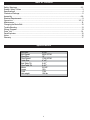
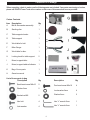
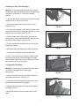
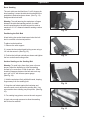
6” X 48”Belt & 10”Disc Sander
Owner’s Manual
Model: 50-120
Record the serial number and date of purchase
in your manual for future reference.
Serial number:
Date of purchase:
For more information:
www.rikontools.com
or
[email protected]
For Parts or Questions:
Part # 50-120M2
[email protected] or 877-884-5167
Operator Safety: Required Reading
IMPORTANT! Safety is the single most important consideration in the operation of this equipment. The
following instructions must be followed at all times.
There are certain applications for which this tool was designed. We strongly recommend that this tool not
be modified and/or used for any other application other than that for which it was designed. If you have
any questions about its application, do not use the tool until you have contacted us and we have advised
you.
General Safety Warnings
KNOW YOUR POWER TOOL. Read the owner’s manual carefully. Learn the tool’s
applications, work capabilities, and its specific potential hazards.
ALWAYS GROUND ALL TOOLS.
If your tool is equipped with a three-pronged plug, you must plug it into a three-hole electric
receptacle. If you use an adapter to accommodate a two-pronged receptacle, you must attach the
adapter plug to a known ground. Never remove the third prong of the plug.
ALWAYS AVOID DANGEROUS ENVIRONMENTS.
Never use power tools in damp or wet locations. Keep your work area well lighted and clear of clutter.
ALWAYS REMOVE THE ADJUSTING KEYS AND WRENCHES FROM TOOLS AFTER USE.
Form the habit of checking to see that keys and adjusting wrenches are removed from the tool before
turning it on.
ALWAYS KEEP YOUR WORK AREA CLEAN. Cluttered areas and benches invite accidents.
ALWAYS KEEP VISITORS AWAY FROM RUNNING MACHINES.
All visitors should be kept a safe distance from the work area.
ALWAYS MAKE THE WORKSHOP CHILDPROOF.
Childproof with padlocks, master switches, or by removing starter keys.
NEVER OPERATE A TOOL WHILE UNDER THE INFLUENCE OF DRUGS,
MEDICATION, OR ALCOHOL.
ALWAYS WEAR PROPER APPAREL.
Never wear loose clothing or jewelry that might get caught in moving parts. Rubber-soled footwear is
recommended for the best footing.
ALWAYS USE SAFETY GLASSES AND WEAR HEARING PROTECTION.
Also use a face or dust mask if the cutting operation is dusty.
NEVER OVERREACH.
Keep your proper footing and balance at all times.
NEVER STAND ON TOOLS.
Serious injury could occur if the tool is tipped or if the cutting tool is accidentally contacted.
2
ALWAYS DISCONNECT TOOLS.
Disconnect tools before servicing and when changing accessories such as blades, bits, and cutters.
ALWAYS AVOID ACCIDENTAL STARTING.
Make sure switch is in “OFF” position before plugging in cord.
NEVER LEAVE TOOLS RUNNING UNATTENDED.
ALWAYS CHECK FOR DAMAGED PARTS.
Before initial or continual use of the tool, a guard or other part that is damaged should be checked to
assure that it will operate properly and perform its intended function. Check for alignment of moving
parts, binding of moving parts, breakage of parts, mounting, and any other conditions that may affect
its operation. A guard or other damaged parts should immediately be properly repaired or replaced.
Special Safety Rules For Belt & Disc Sanders
1. Do not operate this machine until you have read all of the following instructions.
2. Do not attempt to operate this machine until it is completely assembled.
3. Do not turn ON this machine if any pieces are missing.
4. If you are not familiar with the operation of the machine, obtain assistance from a qualified person.
5. It is highly recommended that this machine be firmly mounted to a flat and secure work surface or
stand.
6. Always wear protective eyewear prior to operating this machine.
7. Do not operate this machine if you are under the influence of drugs and/or alcohol.
8. Remove all jewelry prior to operating this machine.
9. Do not wear any gloves while operating this machine.
10. Always make sure the power switch is in the OFF position prior to plugging in the machine.
11. Always make sure the power switch is in the OFF position when doing any assembly or setup
operation.
12. Always wear a dust mask and use adequate dust collection and proper ventilation. Use of sanders
can produce harmful particles while sanding certain types of woods.
13. The use of any accessories or attachments not recommended may cause injury to you and
damage your machine.
14. This machine must be properly grounded.
15. Abrasive discs and belts should be the recommended width and length of the manufacturer.
16. Always keep your face and hands clear of moving parts such as belts and pulleys.
17.Keep power supply cords free of moving parts of the sander. Damaged cords can result in electric
shock.
18. Maintain a 1/16” clearance between the sanding disc, sanding belt and tables.
19.Always support the workpiece with the table or backstop.
20. Remove material or debris from the work area. Keep work area neat and clean.
21.Keep these instructions for future reference.
SAVE THESE INSTRUCTIONS.
Refer to them often.
3
Table of Contents
Safety Warnings..................................................................................................................................2-3
Sander Safety Rules ..........................................................................................................................3
Specifications ........................................................................................................................................4
Contents of Package ............................................................................................................................................5
Assembly ...........................................................................................................................6-8
Electrical Requirements ...........................................................................................................................................9
Operation............................................................................................................10-11
Maintenance ...................................................................................................................................12
Changing the Motor Belt............................................................................................................................12
Trouble Shooting...............................................................................................................................................13
Wiring Diagram.................................................................................................................................13
Parts List .....................................................................................................................................14
Parts Explosion...........................................................................................................................................15
Notes .............................................................................................................................................16
Warranty .............................................................................................................................................17
Specifications
Belt Size
Belt Speed
Disc Size
Disc Speed
Table Size
Belt Table Tilt
Disc Table Tilt
Motor
Amps
Volts
Net weight
6”x48”
2030 SFPM
10”
1720 SFPM
4” x 8”
0-90 o
0-45 o
3/4 HP
10A
110V
104 lbs
4
Contents of Package
When unpacking, check to make sure the following parts are included. If any parts are missing or broken,
please call RIKON Power Tools at the number on the cover of this manual as soon as possible.
Carton Contents
Item
A
Description
Belt & disc sander assembly
Qty
1
B
Sanding disc
1
C
Table support w/scale
1
D
Table support
1
E
Work table for belt
1
F
Miter Gauge
1
G
Work table for disc
1
H
Locking knob for table support
2
I
Mount, support table
1
J
Mount, support table w/indicator
1
K
Bag of loose parts
1
H
Owner’s manual
1
List of loose parts in bag
Description
Qty
Sunk head screw M6x16
2
Washer 6mm
2
Knurled nut M6
Description
Qty
Pan head screw M6x16
4
Lock washer 6mm
4
2
Washer 6mm
2
Hex. bolt
4
Hex “L” wrench 3mm
1
Lock washer
4
Hex “L” wrench 6mm
1
5
Assembly
Securing Sander Base Assembly to Workbench
The sander base must be secured before using.
Attach a large C-Clamp to each side of the sander
and the workbench. Or, permanently mount following
the instructions below:
1. Place the sander on the workbench in its final
operating location.
2. Place a pencil through the mountong holes of the
sander base (42) and mark the hole locations on
workbench.
Fig. 01
3. Remove sander and drill four 3/8 inch holes through
the workbench.
4. Align sander base over holes and secure using four
5/16 inch screws (or larger) and hex nuts.
(See Fig. 01)
Mounting Sanding Disc and Guard
1. Locate sanding disc (22) and peel backing off
disc.
2. Align perimeter of sanding disc over plate. When
aligned, press disc firmly onto disc.
Fig. 02
3. Position disc guard (27) onto lower portion of
sanding disc so that the mounting holes align.
4. Using a Phillips screwdriver, fasten two pan head
screws (found in parts bag) through disc guard.
(See Fig. 02)
Installing the Belt Table
1. Place the work table for belt on the work support.
2. Insert two countersink head screws through work
table and the work support slot.
3. Put a 6mm washer and a wing nut on the screw
and tighten. (See Fig. 03)
Fig. 03
6
Installing the Disc Table Assembly
Warning: To avoid jamming the workpiece or fingers
between the table and sanding surface, the table edge
should be a maximum of 1/16 in from sanding
surface.
1. Use two M6x16 pan head screws to fasten the table
support mount to the front of sander.
2. Place the support table w/scale onto the table
support mount.
Fig. 04
3. Put a 6mm flat washer on the table lock knob, and
place the knob into the tilt scale plate and mount. Hand
tighten it only at this time. (See Fig. 04)
4. Place the table onto table support; align the four
screws which are preassembled under the table with
the holes of table support. (See Fig. 05)
5. Put the external lock washer and hex nut onto the
screws, and tighten.
Fig. 05
6. Adjust the table and retighten the table lock knobs.
7. Loosen the four M6 hex nuts under the table.
8. Use a 1/16 inch drill bit as a spacer. Place the drill
bit between the disc and the front edge of the table.
Hold the table against the 1/16 inch drill bit and tighten
the four M6 hex nuts. (See Fig. 06)
Leveling Table Assembly
Warning: To avoid injury from accidental start, make
sure tool is unplugged before making any
adjustments.
Fig. 06
1. Using a combination square, check the angle of
work table with the disc. (See Fig. 07)
2. If the table is not 90 degrees with the disc, loosen
the table lock knob screw and tilt table.
3. Adjust worktable square to the disc and retighten
the table lock knob.
4. Adjust the pointer to the zero mark on the scale
plate.
Fig. 07
7
Installing the Sanding Belt
Warning: To avoid injury from accidental start,
make sure tool is unplugged before making any
adjustments.
On the under side of the sanding belt, you will find
a “direction arrow”. The sanding belt must run in the
direction of this arrow so that the splice does not
come apart.
Fig. 08
1. Slide tension lever to the right to release the belt
tension. (See Fig. 08)
2. Place the sanding belt over the drums with the
direction arrow pointing in the proper direction.
(See Fig. 09) Make sure the belt is centered on both
drums.
3. Slide tension lever to the left to apply belt tension.
4. Tighten hex socket screw when bed is in desired
position.
Fig. 09
Tensioning and Tracking
1. Plug in the power cord. Turn the switch “ON” and
immediately “OFF”, noting if the belt tends to slide
off the idler drum or drive drum.
2. If the sanding belt moves toward the disc, turn the
tracking knob clockwise 1/4 turn. (See Fig. 10)
3. If the sanding belt moves away from the disc, turn
the tracking knob counterclockwise 1/4 turn.
4. Turn switch “ON” and immediately “OFF” again,
noting belt movement. Readjust tracking knob if
necessary.
Fig. 10
On/Off Switch
The On/Off Locking Switch needs to have the switch
key inserted before the switch can be used (key
located in parts bag). This feature prevents
unauthorized use of the sander. (See Fig. 11)
CAUTION: Never walk away from sander when
machine is running. Always lock the switch in the Off
position and unplug from the power supply when not
in use.
Fig. 11
8
Electrical Requirements
In the event of a malfunction or breakdown, grounding provides a path of least resistance for electric
current to reduce the risk of electric shock. This tool is equipped with an electric cord having an
equipment-grounding conductor and a grounding plug. The plug must be plugged into a matching
outlet that is properly installed and grounded in accordance with all local codes and ordinances.
Do not modify the plug provided. If it will not fit the outlet, have the proper outlet installed by a
qualified electrician.
Improper connection of the equipment-grounding conductor can result in a risk of electric shock. The
conductor, with insulation having an outer surface that is green with or without yellow stripes, is the
equipment-grounding conductor. If repair or replacement of the electric cord or plug is necessary, do
not connect the equipment-grounding conductor to a live terminal.
Check with a qualified electrician or service personnel if the grounding instructions are not completely
understood, or if in doubt as to whether the tool is properly grounded.
Use only three wire extension cords that have three-prong grounding plugs and three-pole receptacles
that accept the tool’s plug.*
Repair or replace a damaged or worn cord immediately.
This tool is intended for use on a circuit that has an outlet that looks the one illustrated in Figure A
below. The tool has a grounding plug that looks like the grounding plug as illustrated in Figure A
below. A temporary adapter, which locks like the adapter as illustrated in Figure B below, may be used
to connect this plug to a two-pole receptacle, as shown in Figure B if a properly grounded outlet is not
available.** The temporary adapter should only be used until a properly grounded outlet can be
installed by a qualified electrician. The green colored rigid ear or tab, extending from the adapter,
must be connected to a permanent ground such as a properly grounded outlet box.
* Canadian electrical codes require extension cords to be certified SJT type or better.
** Use of an adapter in Canada is not acceptable.
9
Operation
Bevel Sanding
The work table can be tilted from 0 to 45 degrees for
bevel sanding. Loosen the table lock knob and tilt the
worktable to desired angle as shown. (See Fig. 12)
Retighten table lock knob.
Warning: To avoid jamming the workpiece or fingers
between the table and sanding surface, the table
should repositioned on the table support to retain a
maximum of 1/16” distance between sanding surface
and table.
Fig. 12
Positioning the Belt Bed
A bed locking hex socket head screw locks the belt
bed in a vertical or horizontal position.
To adjust vertical position:
1. Remove the work support.
2. Loosen the hex socket head locking screw using a
1/4 inch hex wrench. (See Fig. 13)
3. Position the belt bed vertically as shown and tighten
the hex socket head locking screw.
Fig. 13
Surface Sanding on the Sanding Belt
Warning: To avoid injury from slips, jams or thrown
pieces, adjust the backstop to clear the sanding
surface by no more than 1/16th of and inch. When
checking clearance between the belt and work support, use a 1/16” drill bit as a spacer gauge.
(See Fig. 14)
1. Hold the workpiece firmly with both hands, keeping
fingers away from the sanding belt.
Fig. 14
2. Keep the end butted against the backstop and
move the work evenly across the sanding belt. Use
extra caution when sanding very thin pieces. (See Fig.
15)
3. For sanding long pieces, remove the work support.
4. Apply only enough pressure to allow the sanding
belt to remove material.
Fig. 15
10
End Sanding on the Sanding Belt
To sand the end of a long workpiece, it is recommended to sand with the belt in the vertical position.
1. To raise the belt to the vertical position, follow the
instructions in “Positioning Belt Bed” on the previous
page.
2. Install the worktable assembly.
3. Move the work evenly across the sanding belt.
(See Fig. 16)
Fig. 16
Sanding Curved Edges
Always sand inside curves on the idler drum as
shown.(See Fig. 17)
Warning: Never attempt to sand the ends of a
workpiece on the idler drum, applying the end of the
workpiece to the idler drum could cause the workpiece
to fly up and result in an injury.
Fig. 17
Always sand outside curves on the left side of center
on the sanding disc as shown. (See Fig. 18)
Warning: Applying the workpiece to the right side of
the disc could cause workpiece to fly up (kickback)
and result in an injury.
Fig. 18
Sanding Small End Surfaces on the Sanding Disc
Note: Use of a miter gauge is recommended for this
operation.
Always move the work across left side of center on
the sanding disc face as shown. (See Fig. 19)
Warning: Applying the workpiece to the right side of
the disc could cause workpiece to fly up( kickback)
and result in an injury.
Fig. 19
11
Maintenance
Warning: For your safety, remove the plug from
power source outlet before adjusting, maintaining, of
lubricating your belt and disc sander.
1. Apply a light coat of paste wax to the worktable to
make feeding stock easier, and reduce rust.
2. Use compressed air to frequently blow out dust and
debris from sander and motor. (See Fig. 20)
Warning: To avoid electrocution or fire, any repairs to
electrical systems should be done only by qualified
service technicians. Unit must be reassembled
exactly to factory specifications.
Fig. 20
3. If power cord is worn, cut, or damaged in any way,
have it repaired immediately.
Changing the Motor Belt
1. Using a Phillips screwdriver, remove the three pan
head screws located in the cover. (See Fig. 21)
2. Remove the cover.
Fig. 21
3. Loosen four M8 hex head screws to allow the
pulleys to shift enough to place belt around them.
Place belt around motor pulley and drive pulley as
shown. (See Fig. 22)
4. Adjust tension of the belt by putting a wrench in
adjusting gap. Push up on wrench to tighten tension
between pulleys.
5. Tighten the four M8 hex head screws carefully.
6. Test belt tension by placing fingers on either side of
the belt and squeeze. There should be about a 1/4
inch give to the belt. (See Fig. 23)
Fig. 22
Note: Too much tension on pulley belt may cause
increased noise and over load the motor. Not enough
tension on the pulley belt may cause belt to fail
prematurely.
7. Locate the pulley cover and position inside the
edges of pulley housing.
8. Using a Phillips screwdriver, reinstall and tighten
the three pan head screws.
Fig. 23
12
Troubleshooting
SYMPTOM
PROBABLE CAUSE
REMEDY
Sander does not operate
1. Not plugged into wall outlet.
2. Locking key is not inserted.
3. Power switch defective.
4. Motor or wiring problem.
1. Plug into wall outlet.
2. Insert locking key.
3. Replace power switch.
4. Take to a qualified technician.
Motor slows when sanding
1. Timing belt is too tight.
2. Applying too much pressure
on work piece.
1. Decrease tension.
2. Apply less pressure to work
piece when sanding.
Sanding Belt runs off drums
1. Not tracking proplerly.
1. Adjust tracking.
Wood burns while sanding
1. Sanding Disc or Belt is loaded
with debris.
1.Clean or replace disc or belt.
Sander makes excessive noise
1. Timing belt too tight, bearings
need oil.
1. Decrease tension, oil bearings.
Wiring Diagram
13
Parts List
Key
No.
39
40
41
42
43
44
45
46
47
48
49
50
51
52
53
54
55
56
57
58
59
60
61
62
63
64
65
66
67
68
69
70
71
72
73
74
75
76
77
Key
No. Description
Part No.
1 Sanding Belt 152x1219mm
1-JL61020032
2 Bed
1-JL61021000-050W
3 Knob
1-JL20061101/2-001S
4 Washer
1-WSH8GB96B
5 Wing screw
1-JL61040006
6 Sunk head screw M6x16
1-M6X16GB818B
7 Work table for belt
1-JL61040008-050W
8 Work support, sander belt
1-JL61040007-001S
9 Lock pin, work support
1-JL61040004
10 Wing nut M6
1-JL20061003-001S
11 Lock wahser-helical 5mm
1-WSH5GB862D2Z
12 Pan head Screw M5x8
1-M5X14GB818B
13 Pan head Screw M5x16
1-ST4D2X25GB845B
14 Switch housing
1-JL60062001-049S
15 No-volt switch
1-J-9301B
17 Bearing spacer
1-JL61020008
18 Bearing cap
1-JL61020007
19 Socket head screw M8x10
1-M8X10GB80B
20 Drive drum
1-JL61020006
21 Cover, switch Housing
1-JL60062002-049S
22 Pad-254mm dia. Sander paper 1-JL61020033
23 Screw-pan cross M6x12
1-M6X10GB70Z
24 Disc
1-JL61030001
25 Support, sanding disc
1-JL61030002
26 Tapping screw M4x12
1-M5X40GB70Z
27 Disc guard
1-JL61010005-050W
28 Disc shroud
1-JL61010006-001S
29 Hex nut M6
1-M6GB6170Z
30 Pan head screw M6x16
1-M6X16GB5781Z
31a Mount, table support, left
1-JL61030005-001Y
31b Mount, table support, right
2-JL61034000-001Y
32a Table support, left
2-JL61032000-001Y
32b Table support,right
2-JL61033000-001Y
33 Table
1-JL61030010-001G
34 Dust collector
1-JL61010003-001S
35 Pan head screw M5x16
1-M5X16GB818B
36 Clamp handle
1-JL61010014-001Y
37 Handle
1-JL61010013-050W
38 Pan head screw M5x16
1-M6X16GB818B
14
Description
Part No.
Cast Base
1-JL61010001-001G
Motor Cover
1-JL61010002-001S
Safety guard, sanding belt lower 1-JL61010012-001S
Pan head screw M5x8
1-M5X10GB818Z
Thread M6x145
1-M6X145GB818Z
Rubber sleeve
1-JL61010011-001S
Support stem
1-JL61010010
Lock base sander belt
1-JL61020026-001G
Motor
1-G3512674
Hex head screw
1-M8X16GB5781Z
Lock washer
1-WSH8GB93Z
Drive Pulley
1-JL61020027
Countersink Washer
1-WSH6GB5287Z
Drive pulley
1-JL61020001
Pulley Cover
1-JL61010004-001S
Timing Belt
1-JL61020034
Drive Pulley
1-JL61020002
Flat head screw M5x25
1-M6X20GB70Z
Bearing support
1-JL61020004
Lock plate sander plate
1-JL61020005-050A
Hex socket cap screw M8x25
1-M8X25GB5783B
Retaining ring 15mm
1-CLP15GB894D1B
Ball Bearing
1-BRG80202GB278
Drive Shaft
1-JL61020025
Panhead screw M5x16
1-M5X16GB818B
Rubber washer
1-JL61020021-001S
Tension Lever
1-JL61020023-050W
Lever Spacer
1-JL61020013
Rubber washer
1-JL60020018
Index spring
1-JL61020020
Rubber bushing
1-JL61020022
Retaining ring 12mm
1-CLP12GB894D1B
Ball bearing
1-BRG80101GB278
Idler Drum
1-JL61020017
Idler Shaft
1-JL61020016
Drum guide
1-JL61022000
Index spring
1-JL61020015
Power cord w/plug
1-JL20072101
“D” shape rubber bushing
1-JL61010009-001S
Parts Explosion
15
Notes
16
Warranty
2-Year Limited Warranty
RIKON Power Tools/Richen Enterprise, Inc. (“Seller”) warrants to only the original retail
consumer/purchaser of our products that each product be free from defects in materials and
workmanship for a period of two (2) years from the date the product was purchased at retail. This
warranty may not be transferred.
This warranty does not apply to defects due directly or indirectly to misuse, abuse, negligence,
accidents, repairs, alterations, lack of maintenance or normal wear and tear. Under no
circumstances will Seller be liable for incidental or consequential damages resulting from defective
products. All other warranties, expressed or implied, whether of merchantability, fitness for
purpose, or otherwise are expressly disclaimed by Seller. This warranty does not cover products
used for commercial, industrial or educational purposes.
This limited warranty does not apply to accessory items such as blades, drill bits, sanding discs or
belts and other related items.
Seller shall in no event be liable for death, injuries to persons or property, or for incidental,
contingent, special, or consequential damages arising from the use of our products.
To take advantage of this warranty proof of purchase documentation, which includes date of
purchase and an explanation of the complaint, must be provided.
The Seller reserves the right to effect at any time, without prior notice, those alterations to parts,
fittings, and accessory equipment which they may deem necessary for any reason whatsoever.
To take advantage of this warranty, please fill out the enclosed warranty card and send it to:
RIKON Warranty
110 Cummings Park
Woburn, MA 01801
The card must be entirely completed in order for it to be valid. If you have any questions
please contact us at 877-884-5167 or [email protected].
17
For more information:
110 Cummings Park
Woburn, MA 01801
877-884-5167/781-933-8400
[email protected]
www.rikontools.com
Copyright Richen Enterprise, Inc. 2005
Printed in China 6/06