1
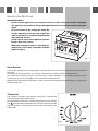
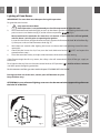
Built-in Gas Ovens
SC 310 ..
Manual for Installation, Use and Maintenance
GB
Customer Care Department • The
T : 01949 862 012
Group Ltd. • Harby Road • Langar • Nottinghamshire • NG13 9HY
E : [email protected]
W : www.cda.eu
F : 01949 862 003
2
Important
This appliance is designed and manufactured solely for the cooking of domestic (household) food and
is not suitable for any non domestic application and therefore should not be used in a commercial
environment.
The appliance guarantee will be void if the appliance is used within a non domestic environment i.e. a
semi commercial, commercial or communal environment.
The CDA Group Ltd cannot be held responsible for injuries or losses caused by incorrect use or installation of this product. Please note that CDA reserve the right to invalidate the guarantee supplied with
this product following incorrect installation or misuse of the appliance.
Appliance Information:
Please enter the details on the appliance rating plate below for reference, to assist CDA Customer Care
in the event of a fault with your appliance and to register your appliance for guarantee purposes.
Appliance Model
Serial Number
Declaration of CE Conformity
This oven has been designed to be used only for cooking.
Any other use (such as heating a room) is improper and dangerous.
This oven has been designed, constructed, and marketed in compliance with:
−−
−−
−−
−−
safety requirements of EU Directive “Gas” 2009/142/EC;
safety requirements of EU Directive “Low voltage” 2006/95/EC;
safety requirements of EU Directive “EMC” 2004/108/EC;
requirements of EU Directive 93/68/EEC.
GB
3
Before Using for the First Time
−−
Read the instructions carefully before installing and using the appliance.
−−
After unpacking the appliance, make sure it is not damaged. In case of doubt, do not use the
appliance and contact your supplier or a qualified engineer.
−−
Remove all packaging and do not leave the packing material (plastic bags, polystyrene, bands etc)
in easy reach of children as they may cause serious injury. The packaging materials are recyclable.
−−
The appliance should be installed and all the gas/electrical connections made by a qualified engineer in compliance with local regulations in force and following the manufacturer’s instructions.
−−
Do not attempt to modify the technical properties of the appliance, as it may become dangerous
to use.
Important Precautions and Recommendations
for Use of Electrical Appliances
Use of any electrical appliance implies the necessity to follow a series of fundamental rules. In particular:
−−
never touch the appliance with wet hands or feet;
−−
do not operate the appliance barefooted;
−−
do not allow children or disabled people to use the appliance without your supervision.
The manufacturer cannot be held responsible for any damages caused by improper, incorrect or unreasonable use of the appliance.
Using the Oven for the First Time
You are advised to carry out the following operations:
−−
Assemble the interior of the oven as described under the heading “Cleaning and maintenance”
−−
Switch the empty oven ON at maximum temperature for about two hours to eliminate traces of
grease and smell from the components.
−−
Let the oven cool down, switch off the electrical supply, then clean the inside of the oven with a
cloth soaked in water and neutral detergent and dry thoroughly.
4
Important Safeguards and Recommendations
−−
Do not carry out any cleaning or maintenance without first disconnecting the appliance from the
electrical supply.
−−
During and after use of the oven, certain parts will become very hot. Do not touch hot parts.
−−
After use always ensure that the controls are in the OFF position (
−−
Household appliances are not intended to be played with by children.
−−
Keep children away from the oven during use.
−−
Children, or persons with a disability which limits their ability to use the appliance, should have a
responsible person to instruct them in its use. The instructor should be satisfied that they can use
the appliance without danger to themselves or their surroundings.
−−
WARNING
When correctly installed, your product meets all safety requirements laid down for this type of
product category. However special care should be taken around the rear or the underneath of the
appliance as these areas are not designed or intended to be touched and may contain sharp or
rough edges, that may cause injury.
−−
Fire Risk! Do not store inflammable materials inside the oven.
−−
Always use oven gloves when removing the shelves and food trays from the oven whilst hot.
−−
Clean the oven regularly and do not allow fat or oils to build up in the oven base or trays. Remove
spillages as soon as they occur.
−−
Do not line the oven walls with aluminium foil. Do not place baking trays or the drip tray on the
base of the oven chamber.
−−
Always stand back from the oven when opening the oven door to allow steam and hot air to escape before removing the food.
−−
Do not hang towels, dishcloths or other items on the oven or its handle – as this could be a fire
hazard.
−−
Make sure that electrical cords connecting other appliances in the proximity cannot become entrapped in the oven door.
−−
Before disposing of an unwanted appliance, it is recommended that it is made inoperative and
that all potentially hazardous parts are made harmless.
−−
Important: This appliance has been designed for domestic use only. The appliance is NOT suitable
for use within a semi-commercial, commercial or communal environment.
−−
Safe food handling: leave food in the oven for as short a time as possible before and after cooking. This is to avoid contamination by organisms which may cause food poisoning. Take particular
care during warmer weather.
-
).
5
Control Panel
Fig. 1
1
2
3
Controls Description
1.
Gas oven/gas grill control knob
2.
60’ timer control knob
3.
Oven light control knob
Notes:
−−
The electric ignition is incorporated in the thermostat control knob.
−−
The appliance has a safety valve system fitted, the flow of gas will be stopped if and when the
flame should accidentally go out.
CAUTION:
If the burner is accidentally extinguished, turn the gas off at the control knob and wait at least 1
minute before attempting to relight.
CAUTION:
Gas appliances produce heat and humidity in the environment in which they are installed.
Ensure that the cooking area is well ventilated by opening the natural ventilation grilles or by
installing an extractor hood connected to an outlet duct.
CAUTION:
If the appliance is used for a prolonged time it may be necessary to provide further ventilation
by opening a window or by increasing the suction power of the extractor hood (if fitted).
6
Gas Oven
Technical Features
The oven is furnished completely clean.
It is advisable however, upon first use, to turn the oven on to the maximum temperature to eliminate
possible traces of grease from the oven burner.
The same operation shall be done with the gas grill.
This oven is fitted with:
−−
−−
One gas oven burner (2,70 kW), located at the bottom, providing self-ignition and safety device.
One gas grill burner (2,10 kW), placed on the top, providing self-ignition and safety device.
Operating Principles
Heating and cooking in the gas oven are obtained in the following ways:
a.
by Normal Convection
The heat is produced by the oven gas burner.
b.
by Radiation
The heat is radiated by the gas grill.
Cooling Fan Motor
This appliance incorporates a safety cooling fan motor to achieve optimum efficiency of the controls,
ensure lower surface temperatures are maintained and cool the internal components.
The cooling fan motor turns on automatically when igniting the oven or grill burner.
It may run on (for various minutes) even after the oven or grill burner has been turned off.
The duration of this time is dependent on previous cooking temperature and duration.
ATTENTION:
The oven door becomes very hot during operation and very hot steam goes out from the area
below the control panel. Keep children away.
The door is hot, use the handle.
During use the appliance becomes hot.
Care should be taken to avoid touching the heating elements inside the oven.
7
How to Use the Oven
IMPORTANT NOTES:
−− Do not use the appliance in case of power failure or if the cooling fan motor is damaged.
The appliance may overheat and get damaged due to the non-operation of the cooling fan
motor.
−−
−−
In case of failure of the cooling fan motor during the operation of the gas oven or grill, the
oven or grill burner is turned off automatically
after about 20 minutes.
In that case do not use the appliance and contact the after-sales service.
When the cooling fan motor is operating correctly there is an air flow in the top area of the
appliance (fig. 2).
Fig. 2
Oven Burner
The gas flow to the burner is regulated by a thermostat which allow to maintain the oven temperature
constant.
The control of the temperature is assured by a thermostatic probe positioned inside the oven.
The probe must be always kept in its housing, in a clean condition, as an incorrect position or encrustment may cause an alteration in the control of the temperature.
Moreover, the thermostat is fitted with a safety valve which automatically shuts off the gas supply when
the flame goes out.
Thermostat
The numbers printed on the control panel (fig. 3) indicate the
increasing oven temperature value.
To regulate the temperature, set the knob to the chosen number.
The
symbol close to the maximum position indicates that the
electric ignition is incorporated into the knob (activated by the
knob itself ).
Fig. 3
8
Lighting of Oven Burner
IMPORTANT: The oven door must be open during this operation.
To ignite the oven burner:
1
2.
Fully open the oven door.
If this operation is not performed you should not proceed to light the oven.
Press the thermostat knob throughly to start up the electric ignition and, keeping the knob under
pressure turn it anti-clockwise (fig. 4) to the maximum position
(fig. 3).
Never continue this operation for more than 15 seconds. If the burner has still not ignited,
wait for about 1 minute prior to repeating the ignition.
In case of mains failure, to light the oven manually, approach a flame to the hole “A” of the floor (fig.
5), then press and turn the thermostat knob (fig. 4).
3.
Wait about ten seconds after lighting the burner to release the knob (priming time of the thermocouple).
4.
Check that the burner has lit; if not, turn the knob clockwise back to “ ” (OFF) and repeat the
procedure from step 1.
5.
Close the oven door slowly and adjust the thermostat knob on the desired setting.
If the flame extinguishes for any reason, the safety valve will automatically shut off the gas supply to
the burner.
To re-light the burner, first turn the oven control knob to OFF position (“ ”), wait for at least 1 minute
and then repeat the lighting procedure.
For the correct use of the gas oven see the chapter “COOKING WITH GAS OVEN”.
During and after use of the oven, certain parts will become very hot.
Keep children away.
ATTENTION: In case of manual lighting, never turn the thermostat before approaching a flame to
the hole “A” of the floor.
A
Fig. 4
Fig. 5
9
Lighting of Gas Grill Burner
IMPORTANT: The oven door must be open during this operation.
To light the burner, you need to:
1
Fully open the oven door.
If this operation is not performed you should not proceed to light the oven.
2
Press the thermostat knob throughly to start up the electric ignition and, keeping the knob under
pressure turn it clockwise (fig. 6) to position
(fig. 3).
Never continue this operation for more than 15 seconds. If the burner has still not ignited,
wait for about 1 minute prior to repeating the ignition.
In case of mains failure, to light the grill manually, put a flame to the right and left side of the burner (fig. 7), then press and turn the thermostat knob (fig. 6).
3.
Wait about ten seconds after the burner lighting before releasing the knob (priming time of the
thermocouple).
4.
Check that the burner has lit; if not, turn the knob anti-clockwise back to “ ” (OFF) and repeat the
procedure from step 1.
5.
The oven door must always be kept half-open when the grill is in operation.
For correct use see chapter “TRADITIONAL GRILLING”.
If the flame extinguishes for any reason, the safety valve will automatically shut off the gas supply to
the burner.
To re-light the burner, first turn the grill control knob to OFF position (“ ”), wait for at least 1 minute
and then repeat the lighting procedure.
During and after use of the grill, certain parts will become very hot.
Keep children away.
ATTENTION: In case of manual lighting, never turn the thermostat before approaching a flame
to the burner.
Fig. 6
Fig. 7
10
Cooking With Gas Oven
Before introducing the food, preheat the oven to the desired temperature.
For a correct preheating operation, it is advisable to remove the tray from the oven and introduce it
together with the food, when the oven has reached the desired temperature.
Check the cooking time and turn off the oven 5 minutes before the theoretical time to recuperate the
stored heat.
Oven Light
The oven provides an interior lamp to allow the visual
inspection during the cooking.
To light the oven lamp turn the knob indicated in fig. 8
to position
.
Traditional Grilling
Warning: The grill burner must be used with the
door ajar only.
Leave to warm up for approximately 5 minutes with the
door ajar.
Place the food inside positioning the rack as near as
possible to the grill.
Insert the drip pan under the rack to collect the cooking juices.
Fig. 8
The operation of the grill should not exceed 30 minutes.
Attention: The oven door becomes very hot during operation.
Keep children away.
Fig. 9
WARNING !!
The grill burner must be used with the
door ajar only.
The cooling fan air flow (below the control panel) allows a correct discharging of
the hot air coming from the inside of the
cavity.
Do not use the grill burner if the cooling
fan is not operating (e.g. mains failure,
cooling fan broken).
11
Cooking Guide
Your gas oven is a newly designed oven which incorporates an indirect burner located under the oven
base plate.
If you have previously been used to cooking with gas you may need to slightly alter your cooking methods.
The bottom of the oven is hot and is ideal for browning the underside of shallow pastry dishes and
pizzas.
Other items should be cooked nearer the top of the oven.
When baking cakes, scones etc on more than one shelf the best results will be achieved by swapping the
shelf positions over half way through the cooking process.
Safety
NEVER allow fat to build on the oven base.
As with all ovens, clean and empty fat regularly from the trays and oven base to avoid the possibility of
fat fires.
The oven incorporates a safety cooling fan motor to achieve optimum efficiency of the controls, ensure
lower surface temperatures are maintained and cool the internal components.
However, the oven door can become hot - keep children away from this appliance.
NEVER place anything on the bottom of the oven.
Do not line the oven walls with aluminium foil.
Do not place baking trays or the drip tray on the base of the oven chamber.
12
Temperature recipe guide
MARK
APPROX.
TEMP.
HEAT OF
OVEN
1/2
125°C
257°F
Very cool oven
Meringue cakes, slow cooking items.
1
140°C
275°F
Cool oven
Milk puddings, very rich fruit cakes,
i.e., Christmas.
2
150°C
300°F
Cool or slow oven
Stews, casseroles, braising, rich fruit
cakes, i.e., Dundee.
3
160°C
325°F
Cool or slow oven
Biscuits, rich plain cakes i.e., Madeira.
Low temp. roasting.
4
180°C
350°F
Warm oven
Plain cakes, Victoria sandwich, raised
meat pies.
5
190°C
375°F
Moderate oven
Small cakes, savoury flans, fish.
6
200°C
395°F
Fairly hot oven
Plain cakes and buns, swiss rolls, fruit
pies. High temp. roasting.
7
220°C
430°F
Hot oven
Bread and bread rolls etc., scones,
flaky and rough puff pastry, yorkshire
pudding.
8
230°C
450°F
Moderately hot oven
Sausage rolls, mince pies, puff pastry,
pizza.
9
240°C
465°F
Very hot oven
Browning ready cooked dishes.
TYPE OF DISH TO COOK
13
Minute Counter
60’ Timer
The minute counter is a timed acoustic warning device which can be set for a maximum of 60 minutes.
The knob (Fig. 10) must be rotated clockwise as far
as the 60 minute position and then set to the required time by rotating it anticlockwise.
IMPORTANT WARNING:
This is only a mechanical timer.
Remember to turn off the oven/grill manually.
Fig. 10
14
Care and Maintenance
It is advisable to clean when the appliance is cold and especially for cleaning the enamelled parts.
Avoid leaving alkaline or acidic substances (lemon juice, vinegar, etc.) on
the surfaces.
Avoid using cleaning products with a chlorine or acidic base.
WARNING
When correctly installed, your product meets all safety requirements
laid down for this type of product category. However special care
should be taken around the rear or the underneath of the appliance
as these areas are not designed or intended to be touched and may
contain sharp or rough edges, that may cause injury.
Inside of Oven
The oven should always be cleaned after use when it has cooled down.
The cavity should be cleaned using a mild detergent solution and warm
water.
Suitable proprietary chemical cleaners may be used after first consulting
with the manufacturers recommendations and testing a small sample of
the oven cavity. Abrasive cleaning agents or scouring pads/cloths should
not be used on the cavity surface.
NOTE: The manufacturers of this appliance will accept no responsibility
for damage caused by chemical or abrasive cleaning.
Enamelled Parts
All the enamelled parts must be cleaned with a sponge and soapy water
only or other non-abrasive products.
Dry preferably with a micro fibre or soft cloth.
Stainless Steel, Aluminium, Painted Parts and Silk-screen Printed Surfaces
Clean using an appropriate product. Always dry thoroughly.
Stainless steel surfaces: can be cleaned with an appropriate stainless steel
cleaner.
IMPORTANT: these parts must be cleaned very carefully to avoid
scratching and abrasion. You are advised to use a soft cloth and neutral
soap.
Glass Control Panel (Some models only)
Clean using an appropriate product. Always dry thoroughly.
Do not use harsh abrasive cleaners or sharp metal scrapers to clean the
control panel since they can scratch the surface, which may result in shattering of the glass.
IMPORTANT:
Before any operation of cleaning
and maintenance
disconnect the appliance from the
electrical supply.
ATTENTION:
Let the oven cool
down and pay special attention no to
touch the hot heating elements inside the oven cavity.
CAUTION:
Do not use abrasive
substances or nonneutral detergents
as these will irreparably damage the
surface.
CAUTION:
Do not use a steam
cleaner because the
moisture can get
into the appliance
thus make it unsafe.
CAUTION:
Do not store
flammable material
in the oven.
CAUTION:
Do not use harsh
abrasive cleaners
or sharp metal scrapers to clean the
oven door glass since they can scratch
the surface, which
may result in shattering of the glass.
15
Replacing the Oven Lamp
WARNING: Ensure the appliance is switched off before replacing the lamp to avoid the possibility of
electric shock.
−−
Let the oven cavity and the heating elements to
cool down.
−−
Switch off the electrical supply.
−−
Remove the protective cover “A” (fig. 11).
−−
Unscrew and replace the bulb “B” with a new one
suitable for high temperatures (300°C) having the
following specifications: 230V or 220-240V, E14
and same power (check watt power as stamped
in the bulb itself ) of the replaced bulb.
−−
Refit the protective cover “A”.
B
A
Fig. 11
Note: Oven bulb replacement is not covered by your
guarantee.
Assembling and Dismantling of the Side Runner Frames
−−
Fit the side runner frames into the holes on the side walls inside the oven (fig. 12).
−−
Slide the drip pan and rack into the runners as shown in fig. 13.
The rack must be fitted so that the safety catch, which stops it sliding out, faces the inside of the
oven.
−−
To dismantle, operate in reverse order.
Fig. 12
Fig. 13
16
Oven Door
Removing the Oven Door
Take care, the oven door is heavy. If you have any doubts, do
not attempt to remove the door.
The oven door can easily be removed as follows:
−−
Open the door to the full extent (fig. 15).
−−
Open the lever A completely on the left and right hinges
(fig. 16).
−−
Hold the door as shown in fig. 14.
−−
Gently close the door (fig. 19) until left and right hinge
levers A are hooked to part B of the door (fig. 16).
−−
Withdraw the hinge hooks from their location following
arrow C (fig. 18).
−−
Rest the door on a soft surface.
Fig. 15
A
A
BB
Fig. 16
Fig. 17
CC
Fig. 14
Fig. 18
17
Refitting the Oven Door
−−
Hold the door firmly (fig. 19).
−−
Insert the hinge tongues into the slots, making sure that the groove drops into place as
shown in the fig. 20.
−−
Open the door to its full extent.
−−
Fully close the levers “A” on the left and right
hinges, as shown in the figure fig. 21.
−−
Close the door and check that it is properly in
place.
Fig. 19
Removing and Replacing the Inner
Door Glass Pane for Cleaning
If you wish to clean the inner glass of the door, make
sure you follow the precautions and instructions
very carefully.
Replacing the glass pane and the door incorrectly
may result in damage to the oven and may void your
warranty.
IMPORTANT!
−−
Take care, the oven door is heavy. If you have
any doubts, do not attempt to remove the
door.
−−
Make sure the oven and all its parts have cooled down. Do not attempt to handle the parts
of a hot oven.
−−
Take extreme care when handling the glass pane.
Avoid the edges of the glass bumping against any
surface. This may result in the glass shattering.
−−
Do not use harsh abrasive cleaners or sharp metal
scrapers to clean the oven door glass since they
can scratch the surface, which may result in shattering of the glass.
−−
If you notice any sign of damage on any of the
glass panes (such as chipping, or cracks), do not
use the oven. Call your Authorised Service Centre
or Customer Care.
Fig. 20
A
Fig. 21
−−
Make sure you replace the glass pane correctly.
Do not use the oven without glass pane correctly in place.
−−
If the glass pane feels difficult to remove or replace, do not force it. Call your Authorised Repairer
or Customer Care for help.
Note: service visits providing assistance with using or maintaining the oven are not covered by
your warranty.
18
Removing the Inner Pane of Glass
The oven door is fitted with no. 2 panes:
−−
no. 1 outside;
−−
no. 1 inner.
To clean all panes on both sides it is necessary to
remove the inner pane as follows:
1. Lock the door open:
−−
Open the door to the full extent (fig. 22).
−−
Open the lever A completely on the left and
right hinges (fig. 23).
−−
Gently close the door (fig. 24) until left and
right hinge levers A are hooked to part B of
the door (fig. 23).
2. Remove the inner pane:
−−
Gently pull out the inner pane of glass (fig. 25).
−−
Clean the glass with an appropriate cleaner.
Dry thoroughly, and place on a soft surface.
Fig. 22
A
B
Fig. 23
Now you can also clean the inside of the outer
glass.
Fig. 24
Fig. 25
19
After Cleaning, Replace the Inner Glass
Pane
When replacing the inner glass pane, make sure
that:
−−
You replace the pane correctly, as shown. The
pane must be in the position described below
in order to fit into the door and to ensure that
the oven operates safely and correctly.
−−
You take extra care not to bump the edges of
the glass against any object or surface.
−−
You do not force the pane into place. If you are
experiencing difficulties replacing the pane,
remove it and start the process again from the
beginning. If this still does not help, call Customer Care.
D
Fig. 26
Fig. 27
E
To reassemble the inner pane of the oven door operate as follows:
F
1. Make sure the door is locked open (see fig. 24).
2. Replace the inner pane:
−−
Check that the four rubber pads are in place
(D in fig. 26).
IMPORTANT: It is advisable, while refitting the
glass, to keep pressed in position the four rubber pads D, by a finger, to avoid breakage or
slippage of the rubber pads themselves (Fig.
27).
−−
Check that you are holding the pane the correct way. You should be able to read the wording on it as it faces you.
−−
Insert the pane in the left E and right F slide
guides (fig. 27), and gently slide it to the retainers H (Fig. 28).
−−
Unlock the oven door by opening it completely and closing the lever A on the left and
right hinges (fig. 29).
Fig. 28
H
A
Fig. 29
20
Do’s and do not’s
−−
Do always grill with the oven door ajar.
−−
Do read the user instructions carefully before using the oven for first time.
−−
Do allow the oven to heat for about two hours, before using for the first time, in order to expel any
smell from the new oven insulation, without the introduction of food.
−−
Do clean your oven regularly.
−−
Do remove spills as soon as they occur.
−−
Do always use oven gloves when removing food shelves and trays from the oven.
−−
Do not allow children near the oven when in use.
−−
Do not allow fat or oils to build up in the oven tray, or oven base.
−−
Do not place cooking utensils or plates directly onto the oven base.
−−
Do not grill food containing fat without using the grid.
−−
Do not cover the grilling grid with aluminium-foil.
−−
Do not line the oven walls with aluminium foil.
−−
Do not use the oven tray for roasting.
−−
Do not place hot enamel parts in water. Leave them to cool first.
−−
Do not allow vinegar, coffee, milk, saltwater, lemon or tomato juice to remain in contact with enamel parts (inside the oven and on the oven tray).
−−
Do not use abrasive cleaners or powders that will scratch the surfaces and the enamel.
−−
Do not attempt to repair the internal workings of your oven.
−−
Do remove the protective film before the first use.
−−
Do not carry out any cleaning or maintenance without first disconnecting the appliance from the
electrical supply.
−−
Fire risk! Do not store flammable material in the oven.
For Your Safety
The product should only be used for its intended purpose which is for the
cooking of domestic foodstuffs.
Under no circumstances should any external covers be removed for servicing or maintenance except by suitably qualified personnel.
Important Notes
Installation, and any demonstration, information or adjustments are not
included in the warranty.
The oven must be installed by a suitably qualified and registered person
in accordance with the relevant Standards.
ATTENTION:
The appliance gets
very hot, mainly
around the cooking areas. It is
very important that
children are not left
alone in the kitchen
when you are cooking.
21
Advice for the Installer
Appliance installation and maintenance must only be carried out by QUALIFIED TECHNICIANS
and in compliance with the local safety standards.
−−
Failure to observe this rule will invalidate the warranty.
−−
Always disconnect the appliance from the electrical supply before carrying out any maintenance
operations or repairs.
−−
The walls surrounding the oven must be made of heat-resistant material.
−−
Taking care NOT to lift the oven by the door handle.
WARNING
When correctly installed, your product meets all safety requirements laid down for this type of
product category.
However special care should be taken around the rear or the underneath of the appliance as these areas are not designed orintended to be touched and may contain sharp or rough edges, that
may cause injury.
Location
The appliance may be installed in a kitchen, Kitchen/diner or a bed sitting room, but not in a room or
space containing a bath or a shower.
The appliance must not be installed in a bed-sitting room of less than 20m3.
The appliance is designed and approved for domestic use only and should not be installed in a commercial, semi commercial or communal environment.
Your product will not be guaranteed if installed in any of the above environments and could affect any
third party or public liability insurances you may have.
The oven is designed to fit into a cabinet of 600 mm width.
The oven can be built in or built under the kitchen units, but you must ensure that it is properly ventilated.
In the diagram the built in oven is ventilated by means of a space at the top of the kitchen cabinet.
There are many other methods of ventilating your oven.
Consult a qualified engineer for advice.
22
Important
560
591
555
in
0m
595
55
0
54
595
Fig. 30a
20
560
585
Ensure that air can flow freely
around the housing area.
Failure to allow adequate ventilation to the appliance may
result in over heating or damage to adjacent units.
Lift the oven carefully into
position on the shelf, taking
care NOT to lift it by the door
handle.
If you lower the oven door,
you will see 4 screw holes, 2 on
each side of the oven.
The oven should then be secured to the housing by fitting
screws into these holes.
Remember the housing should
not be free standing but secured to the wall and/or adjacent
fittings.
Fig. 30b
23
Fixing the Oven
Introduce the oven into the furniture opening and
fix it with 4 screws (not supplied) as figure 31.
It is essential that the oven rests on a surface which
will support its weight, as the screw fixing is only
complementary.
Adjust the hinges of furniture doors adjacent to the
oven to allow a 4-5 mm gap between the furniture
door and the oven frame.
IMPORTANT:
To avoid damage to the lower trim please note
the following instructions.
The lower trim is designed to allow for good air circulation and the correct opening of the oven door.
Fig. 31
To ensure the trim is not damaged due to the appliance being placed on the floor, the appliance
should be suitably supported as in illustration here
below.
After installation the appliance door should be
slowly opened to ensure no damage has occurred.
No responsibility for lower trim damage will be
accepted if these instructions have not been followed.
Oven
door
Lower trim
Air flow
Fig. 32
24
Provision for Ventilation
––
The appliance should be installed into a room or space with an air supply in accordance with
BS 5440-2: 2000.
––
For rooms with a volume of less than 5m3 - permanent ventilation of 100cm2 free area will be
required.
––
For rooms with a volume of between 5m3 and 10m3 a permanent ventilation of 50cm2 free area
will be required unless the room has a door which opens directly to the outside air in which case
no permanent ventilation is required.
––
For rooms with a volume greater than 10m3 - no permanent ventilation is required.
Note: Regardless of room size, all rooms containing the appliance must have direct access to the
outside air via an openable window or equivalent.
−−
Where there are other fuel burning appliances in the same room, BS 5440-2: 2000 should be consulted to determine the correct amount of free area ventilation requirements.
−−
The above requirements allow also for use of a gas oven and grill but if there are other gas burning
appliances in the same room, consult a qualified engineer.
25
Gas Installation
Important Note
This appliance is supplied for use on NATURAL GAS or LPG (check the gas regulation label attached on
the appliance).
––
Appliances supplied for use on NATURAL GAS: they are adjusted for this gas only and cannot be
used on any other gas (LPG) without modification. The appliances are manufactured for conversion to LPG.
––
Appliances supplied for use on LPG: they are adjusted for this gas only and cannot be used on any
other gas (NATURAL GAS) without modification. The appliances are manufactured for conversion
to NATURAL GAS.
If the NATURAL GAS/LPG conversion kit is not supplied with the appliance this kit can be purchased by
contacting the After-Sales Service.
Installation and Service Regulations (United Kingdom)
It is a legal requirement that all gas appliances are Installed & Serviced by a competent person in accordance with the current editions of the following Standards & Regulations or those regulations appropriate to the geographical region in which they are to be installed:
––
Gas Safety (Installation & Use) Regulations
––
Building Regulations
––
British Standards
––
Regulations for Electrical Installation
Installation and service of any gas product must be made by a suitably qualified and registered person
competent on the type of product being installed or serviced and holding a valid certificate of competence for the work being carried out. Currently the proof of competence is the Accredited Certification
Scheme (ACS) or S/NVQ that has been aligned to the ACS.
It is also a requirement that all businesses or self employed installers are members of a class of person
approved by the Health and Safety Executive.
Failure to install the appliance correctly could invalidate any manufacturers warranty and lead to prosecution under the above quoted regulation.
26
Gas Connection
The installation of the gas appliance to Natural Gas or LP Gas must be carried out by a suitably qualified
and registered installer. Installers shall take due account of the provisions of the relevant British Standards Code of Practice, the Gas Safety Regulations and the Building Standards (Scotland) (Consolidation) Regulations issued by the Scottish Development Department.
Installation to Natural Gas
Installation to Natural Gas must conform to the Code of Practice, etc.
The supply pressure for Natural Gas is 20 mbar.
The installation must conform to the relevant British Standards.
Installation to LP Gas
When operating on Butane gas a supply pressure of 28-30 mbar is required.
When using Propane gas a supply pressure of 37 mbar is required.
The installation must conform to the relevant British Standards.
Warning: Only a suitably qualified and registered installer, also with technical knowledge of electricity
should install the appliance. He should observe the Regulations and Codes of Practice governing such
installation of gas appliances.
Note: It is recommended that the gas connection to the appliance is installed with a flexible connecting
tube made to BS5386.
Notes:
––
Flexible hoses can be used where the sited ambient temperature of the hose does not
exceed 70°C. These hoses must be manufactured in accordance with BS669 part 1 and be of
the correct construction for the type of gas being used.
––
Gas hoses designed for natural gas MUST NOT be used for supplying LPG gas (LPG gas hoses
can be identified by a either a red band or stripe on the rubber outer coating of the hose).
The hose should not be crushed or trapped or be in contact with sharp or abrasive edges.
If installation is to be carried out using a flexible connector (to BS669), then the following points must
be adhered to:
Note: The gas installation pipes and the final connection to the appliance connecting pipe shall be
sufficient size to maintain the heat output of the appliance as specified under installation.
1. The appliance flexible connector should not be subject to undue forces, either in normal use whilst being connected or disconnected.
Fig. 33
2. The appliance flexible connector should not be
subject to excessive heat by direct exposure to flue
products or by contact with hot surfaces.
3. The socket into which the plug of the appliance flexible connector fits should be permanently attached
to a firmly fixed gas installation pipe and positioned
such that the hose hangs freely downwards.
4. The appliance flexible connector should be positioned such that it will not suffer mechanical damage;
eg abrasion from the surrounding kitchen furniture which may be moved in use, such as a door or
drawer, or by being trapped by a stability device.
5. The plug-in connector should be accessible for disconnection after moving the appliance.
27
Installing the Test Point Adaptor
Appliance
gas inlet pipe
Nipple
G 1/2 cylindrical
(ISO 228-1) male
Gasket
G 1/2 cylindrical
(ISO 228-1) female
Conical adaptor
R 1/2 conical
(ISO 7-1) male
Rc 1/2 conical
(ISO 7-1) female
Test point adaptor
Test point
Rc 1/2 conical
(ISO 7-1) female
Fig. 34
Using a suitable leak detection fluid solution (e.g. Rocol) check each
gas connection one at a time by
brushing the solution over the connection.
The presence of bubbles will indicate a leak.
If there is a leak, tighten the fitting
and then recheck for leaks.
LOCK
Arrow
Important !
Use two wrenches to tighten the connection.
Note: take care not to overtighten the conical adaptor, as doing so may crack the test
point adaptor.
Fig. 35
IMPORTANT! Do not use a naked flame to test for leaks.
LOCK
OK
Interpose the
supplied gasket.
Important !
Use two wrenches to tighten
the connection.
Fig. 36
Fig. 37
28
Maintenance and
Conversion to Natural Gas or to LPG
GB Cat: II 2H3+
Table for the Choice of the Injectors
Nominal
power
[kW]
Reduced
power
[kW]
Oven
2,70
Grill
2,10
BURNERS
LPG
G30 (28-30 mbar)
G31 (37 mbar)
Natural Gas
G20 (20 mbar)
Ø injector
[1/100 mm]
Ring
opening
[mm]
Ø injector
[1/100 mm]
Ring
opening
[mm]
0,65
78
Fully open
(*)
120
2 (*)
-
72
Fully open
(*)
110
2 (*)
(*) = Reference value
AIR VENT NECESSARY FOR GAS COMBUSTION = (2 m3/h x kW)
BURNERS
Air necessary for combustion [m3/h]
Oven
5,40
Grill
4,20
IMPORTANT: All intervention regarding installation maintenance and conversion of the appliance must be fulfilled with original factory parts.
The manufacturer declines any liability resulting from the non-compliance of this obligation.
29
Operations to Be Executed for the Replacement of the Injectors of the Oven
and Grill Burners
Some models are provided with a set of injectors for the various types of gas.
If the injectors are not supplied they can be obtained from the “Service Centre”.
Select the injectors to be replaced according to the “Table for the choice of the injectors”.
The nozzle diameters, expressed in hundredths of a millimetre, are marked on the body of each injector.
Oven Burner
−−
Lift and remove the lower panel inside the oven.
−−
Unscrew and remove the burner securing screw “A” (fig. 38).
−−
Withdraw the burner as shown in figure 31 and rest it inside the oven. Take care not to damage the
safety valve probe and the electric ignition electrode.
−−
Using a 7 mm box spanner, unscrew the injector (indicated by the arrow in fig. 39) and replace
it with a new one selected in accordance with the “Table for the choice
of the injectors”.
−−
Regulate the air supply to the oven
burner as indicated in the section
“Regulation of air supply to oven
and grill burners”; then replace the
burner and the other components
repeating the above steps in reverse order.
IMPORTANT: Check the correct
operation of the safety valve and
the ignition electrode.
A
Fig. 38
Fig. 39
30
Grill Burner
−−
Unscrew and remove the burner securing screw “A” (fig. 40).
−−
Withdraw the burner as shown in figure 41. Take care not to damage the safety valve probe and
the electric ignition electrode.
−−
Using a 7 mm box spanner, unscrew the injector (indicated by the arrow in fig. 41) and replace it
with a new one selected in accordance with the “Table for the choice of the injectors”.
−−
Regulate the air supply to the grill burner as indicated in the section “Regulation of air supply to
oven and grill burners”; then replace the burner repeating the above steps in reverse order.
IMPORTANT: Check the correct operation of the safety valve and the ignition electrode.
A
Fig. 40
Fig. 41
31
Regulation of Air Supply to Oven and Grill Burners
To regulate the air supply it is necessary to remove the burners from their housings (figs. 39 - 41).
−−
Using a cross-head screwdriver, slacken the screws “A” securing the air flow regulation collar “B”
(fig. 42) and move the collar forward or backward to increase or reduce the air aperture in accordance with gas type and the indications in the ‘Table for the choice of the injectors’.
IMPORTANT: If the air flow regulation collar “B” is not already fitted on the burner (e.g. oven burner
set in the factory for LPG use), it is supplied with the kit for the gas conversion. In this case the air
flow regulation collar “B” shall be fitted as indicated in figure 42:
–– the collar “B” shall be folded around the burner (one half part at the top and one half part at
the bottom);
–– the throttled section shall be oriented toward the burner deflector (opposite side with respect to the injector).
−−
Replace and light the burners to check the flames.
Fig. 42
rner
Grill bu
Ring opening [mm]
(see the “Table for the choice
of the
injectors”)
A
B
er
burn
Oven
B
1
2
32
Flame
faulty in
primary air
Flame
correct
Flame
with excess
primary air
flong, yellow
and
trembling
clear
interior blue
cone
short and
sharp too blue
interior cone
tending to
detach
Flame correct
Flame faulty in
primary air
CAUSE
air regulating
tube, too
closed
correct
distance of
the tube
Flame with excess
primary air
air regulating
tube, too
open
Adjustment of the Oven Burner Minimum
This needs to be done only for the oven burner (the grill is a fixed capacity) by acting on the thermostat.
In the minimum position the flame must have a length of about 4 mm and must remain lit even with a
brusque passage from the maximum position to that of minimum.
The flame adjustment is done in the following way:
−−
Turn on the oven burner by setting the thermostat knob on maximum position “240”.
−−
Remove the knob and unscrew the by-pass screw “G” (fig. 43) about three times by passing a small
flat screwdriver (Ø 3 mm blade, 100 mm length) through the control panel opening.
Note: for the models with glass control panel, for easy access to the by-pass screw, it is suggested
to remove the control panel itself (fig. 44). To do that unscrew the two screws on the bottom side
of the control panel and then move, toward the outside, the bottom edge of the glass until the
complete extraction of the bottom fixing tongues. Then let it slide downwards to disengage the
top fixing tongues.
−−
Re-mount the knob and let the oven heat up for about 15 minutes, then bring the knob to the
minimum position “125” to operate the thermostat by-pass.
−−
After having removed the knob again and being very careful not to turn the thermostat rod, slowly
screw the by-pass screws “G” (fig. 43) until you obtain a flame of 3-4 mm in height.
−−
Turn off the burner and reassemble the knob.
N.B. For G30/G31 (LPG) the by-pass screw must be fixed thoroughly.
Fig. 43
G
Fig. 44
3
2
2
1
1
33
Mains Electricity Connection
Incorrect installation may be dangerous and the manufacturer can not be held responsible.
Warning! This appliance must be earthed. The manufacturer declines all responsibility for any
problem caused by failure to observe this rule.
THIS APPLIANCE MUST BE CONNECTED TO THE MAINS SUPPLY BY A COMPETENT PERSON, USING FIXED
WIRING VIA A DOUBLE POLE SWITCHED FUSE SPUR OUTLET AND PROTECTED BY A 3A FUSE.
We recommend that the appliance is connected by a qualified electrician, who is a member of the
N.I.C.E.I.C. and who will comply with the I.E.E. and local regulations.
The wires in the mains lead of this appliance are coloured in accordance with the following code:
Green & Yellow = Earth, Blue = Neutral, Brown = Live.
As the colours of the wires in the mains lead for the
appliance may not correspond with the coloured
markings identifying the terminals connecting to the
fuse spur, proceed as follows:
−−
−−
−−
DOUBLE POLE SWITCHED
FUSED SPUR OUTLET
The wire which is coloured green and yellow
must be connected to the terminal marked E
(Earth) or coloured green.
The wire which is coloured blue must be connected to the terminal marked N (Neutral), or
coloured black.
FUSE
The wire which is coloured brown must be connected to the terminal marked L (Live), or coloured red.
ON
Note: Use a 3A Fuse
Assembly and electrical connection should be carried
out by specialised personnel.
When installing this product we recommend you
seek the help of another individual.
USE A 3 AMP FUSE
Fig. 45
34
Appliance Servicing
CDA provide a quality and effective after-sales service to cover all your servicing needs.
Please attach your receipt to this page for safekeeping.
Please help us to help you by having the following information available when booking a service-call:
1.
Model type, make and model – see the product data plate.
2.
Evidence of installation / purchase date.
3.
Retailer where appliance was purchased.
4.
Clear and concise details of the fault.
5.
Full address including postcode and any contact phone numbers.
Contact telephone numbers
CDA Customer Care Department
−−
Telephone: 01949 862012
−−
Fax: 01949 862003
−−
Email: [email protected]
35
Cod. 1104046 - ß3
To contact our Customer Care Department, or for Service,
please contact us on the details below.
Customer Care Department • The
T : 01949 862 012
Group Ltd. • Harby Road • Langar • Nottinghamshire • NG13 9HY
E : [email protected]
W : www.cda.eu
F : 01949 862 003