1
OWNER'S
MANUAL
MODEL NO.
944.527700
®
Caution:
Read and follow
all Safety Rules
and instructions
Before Operating
This Equipment
P
TWO-STAGE
R- ROPELLE
THROWER
• Assembly
• Operation
• Maintenance
• Service and Adjustments
• Repair Parts
Sears Canada, Inc., Toronto, Ontario
MSB 2B8
iMPORTANT
Safe Operation
Practices
for Walk=Behind
Snow Throwers
This snow thrower is capable of amputating hands and feet and throwing objects.
Failure to observe the following safety instructions could result in serious injury.
WARNING: Snow throwers have ex=
posed rotating parts, which can cause
Look for this symbol to point out important safety precautions, it means
CAUTION!!! BECOMEALERT!!! YOUR
SAFETY iS iNVOLVED.
&
terial
discharge
chute.
severethrown
injury from
from the
contact,
or from
maKeep the area of operation clear of all
persons, small children and pets at all
times including startup.
WARNING: Always disconnect
spark
plug wire and place it where it cannot
contact plug in order to prevent acci=
dental starting when setting up, trans=
porting, adjusting or making repairs.
parts
become
extremely
hot engine
during
CAUTION:
Muffler
and other
operation and remain hot after engine
contact,
stay To
away
from
theseburns
areas.on
has stopped.
avoid
severe
_
WARNING: This snow thrower is for
use on sidewalks, driveways and other
WARNING:
be exercised while using on sloping
surfaces.
Dosurfaces.
not use snow
thrower
on
ground level
Caution
should
surfaces above ground level such as
roofs of residences, garages, porches
or other such structures or buildings.
Engine exhaust, some of
components contain or emit chemi=
cals
known to theand
State
of California
its constituents,
certain
vehicle
to cause cancer and birth defects or
other reproductive harm.
Training
1,
Read, understand and follow all instructions on
machine and in the manual(s) before operating
unit. Be thoroughly familiar with the controls and
proper use of the equipment. Know how to stop
unit and disengage the controls quickly.
the
this
the
the
2.
Never allow children to operate the equipment. Never
allow adults to operate the equipment without proper
instruction.
3,
Keep the area of operation clear of all persons, particularly small children.
4,
Exercise caution to avoid slipping or falling, especially
when operating the snow thrower in reverse.
Preparation
1,
Thoroughly inspect the area where the equipment is
to be used and remove all doormats, sleds, boards,
wires, and other foreign objects.
2.
Disengage all clutches and shift into neutral before
starting the engine (motor).
3,
Do not operatethe equipment without wearing adequate
winter garments. Avoid loose fitting clothing that can
get caught in moving parts. Wear footwear that will
improve footing on slippery surfaces.
4,
(f)
(g) Replace gasoline cap securely and wipe up spilled
fuel.
(h) If fuel is spilled on clothing, change clothing immediately.
5,
6,
(d) Never fill containers inside a vehicle or on a truck
or trailer bed with a plastic liner. Always place
containers on the ground, away from your vehicle,
before filling.
(e) When practical, remove gas-powered equipment
from the truck or trailer and refuel it on the ground.
If this is not possible, then refuel such equipment
on a trailer with a portable container, rather than
from a gasoline dispenser nozzle.
Adjust the collector housing height to clear gravel or
crushed rock surface.
Never attempt to make any adjustments while the
engine (motor) is running (except when specifically
recommended by manufacturer).
8,
Always wear safety glasses or eye shields during operation or while performing an adjustment or repair to
protect eyes from foreign objects that may be thrown
from the machine.
Operation
1,
Do not put hands or feet near or under rotating parts,
Keep clear of the discharge opening at all times.
2.
Exercise extreme caution when operating on or crossing gravel drives, walks, or roads, Stay alert for hidden
hazards or traffic.
3,
After striking a foreign object, stop the engine (motor),
remove the wire from the spark plug, disconnect the
cord on electric motors, thoroughly inspect the snow
thrower for any damage, and repair the damage before
restarting and operating the snow thrower.
4.
If the unit should start to vibrate abnormally, stop the
engine (motor) and check immediately for the cause.
Vibration is generally a warning of trouble.
5,
Stop the engine (motor) whenever you leave the operating position, before unclogging the collector/impeller
housing or discharge chute, and when making any
repairs, adjustments or inspections,
(b) Never add fuel to a running engine or hot engine.
(c) Fill fuel tank outdoors with extreme care. Never fill
fuel tank indoors.
Use extension cords and receptacles as specified by
the manufacturer for all units with electric drive motors
or electric starting motors.
7,
Handle fuel with care; it is highly flammable
(a) Use an approved fuel container.
Keep the nozzle in contact with the rim of the fuel
tank or container opening at all times, until refueling is complete. Do not use a nozzle lock-open
device.
6. Whencleaning,repairingor inspectingthe snow
thrower,stopthe engineandmakecertainthe collector/impeller
andall movingpartshavestopped.
Disconnect
thesparkplugwireandkeepthewireaway
fromthe plugto preventsomeonefromaccidentally
startingtheengine.
7. Donotrunthe engineindoors,exceptwhenstarting
theengineandfortransporting
thesnowthrowerinor
outofthe building.Opentheoutsidedoors;exhaust
fumesaredangerous.
8. Exerciseextremecautionwhenoperatingonslopes.
9. Neveroperatethesnowthrowerwithoutproperguards,
andothersafetyprotective
devicesinplaceandworking.
10. Neverdirectthe dischargetowardpeopleor areas
whereproperty
damagecanoccur.Keepchildrenand
othersaway.
11. Donotoverloadthe machinecapacitybyattempting
to clearsnowattoofasta rate.
12. Neveroperatethe machineat hightransportspeeds
onslipperysurfaces.Lookbehindandusecarewhen
operating
in reverse.
13. Disengage
powertothecollector/impeller
whensnow
throweris transported
or notinuse.
14. Useonlyattachments
andaccessories
approvedby
themanufacturer
ofthesnowthrower(suchaswheel
weights,counterweights,
or cabs).
15. Neveroperatethesnowthrowerwithoutgoodvisibility
or light.Alwaysbesureof yourfooting,andkeepa
firmholdonthe handles.Walk;neverrun.
16. Nevertoucha hotengineor muffler.
Clearing
a Clogged
Discharge
Chute
Hand contact with the rotating impeller inside the discharge
chute is the most common cause of injury associated with
snow throwers. Never use your hand to clean out the discharge chute. To clear the chute:
1. SHUTTHE ENGINE OFF!
2.
Wait 10 seconds to be sure the impeller blades have
stopped rotating.
3.
Always use a clean-out tool, not your hands.
Maintenance
1.
2.
and Storage
Check shear bolts and other bolts at frequent intervals
for proper tightness to be sure the equipment is in safe
working condition.
Never store the machine with fuel in the fuel tank
inside a building where ignition sources are present
such as hot water heaters, space heaters, or clothes
dryers. Allow the engine to cool before storing in any
enclosure.
3,
Always refer to operator's manual for important details
if the snow thrower is to be stored for an extended
period,
4,
Maintain or replace safety and instruction labels, as
necessary,
5,
Run the machine a few minutes after throwing snow
to prevent freeze-up of the collector/impeller,
TABLE OF CONTENTS
SAFETY RULES ........................................................
2-3
PRODUCT SPECiFICATiONS ...................................... 4
CUSTOMER RESPONSIBILITIES ................................ 4
WARRANTY ..................................................................
4
ASSEMBLY / PRE-OPERATION ............................... 6-8
OPERATION ............................................................
9=14
MAINTENANCE .....................................................
15-16
MAINTENANCE SCHEDULE ..................................... 15
SERVICE AND ADJUSTMENTS ........................... 17=19
STORAGE ...................................................................
19
TROUBLESHOOTING ................................................
20
REPAIR PARTS .....................................................
22-38
SEARS SERVICE ................................... BACK COVER
LIMITED
TWO (2) YEAR WARRANTY
ON CRAFTSMAN
SNOW THROWER
For two (2) years from date of purchase Sears Canada, Inc. will repair or replace, at Sears option, free of charge
parts which are defective as a result of material or workmanship,
COMMERCIAL OR RENTAL USE:
Warranty on Snow Thrower will be 90 days from date of purchase if used for commercial or rental purposes,
This Warranty
does NOT cover:
1.
Pre=delivery set=up.
2.
Expendable items which become worn during normal use, such as belts, spark plugs, air cleaners,
and shear pins, as well damage to the engine resulting from operating snow thrower with insufficient oil.
3.
Repairs necessary because of operator abuse or negligence, including the failure to operate and main=
tain the equipment according to the instructions contained in the Owner's Manual.
4.
Tire replacement
or repair caused by punctures from outside objects, such as nails, thorns, stumps or glass.
Warranty service is available by returning the Craftsman Snow Thrower to the nearest Sears Service Centre/Department in Canada. This warranty applies only while this product is in use in Canada.
This warranty is in addition to any statutory warranty and does NOT exclude or limit legal rights you may have but
shalll run concurrently with applicable provincial legislation. Furthermore, some provinces do not allow limitations
on how long an implied warranty will last, so the above limitations may not apply to you,
Sears Canada, inc., Toronto, Ontario
CONGRATULATIONS
on your purchase of a new snow
thrower. It has been designed, engineered and manufactured to give best possible dependability and performance.
Should you experience any problem you cannot easily
remedy, please contact your nearest Sears service centre/
department. We have competent, well-trained technicians
and the proper tools to service or repair this unit.
Please read and retain this manual. The instructions will
enable you to assemble and maintain your snow thrower
properly. Always observe the "SAFETY RULES",
SERIAL NUMBER:
DATE OFPURCHASE:
THE MODELAND SERIAL NUMBERSWILL BE FOUND
ON A DECALATTACH ED TOTHE REAR OFTHE SNOW
THROWER HOUSING.
YOUSHOULDRECORDBOTHSERIALNUMBERAND
DATE OF PURCHASE AND KEEPIN A SAFE PLACE
FOR FUTURE REFERENCE.
M5B 2B8
PRODUCT
SPECiFiCATiONS
Gasoline Capacity
and Type:
4.0 Quarts (4,54 Liters)
Unleaded Regular only
Oil Type
(APl SG-SL):
SAE 5W-30 or 10W-30
(0°F to +40°F / -18°C to +5°C)
Synthetic SAE 5W-30 or 10W-30
(below 0°F / -18°C)
Oil Capacity:
28 Ounces (0,8 Liters)
Spark Plug:
Gap:
Champion RC12YC
0,030" (0,762 mm)
CUSTOMER
RESPONSIBiLiTiES
•
Read and observe the safety rules,
•
Follow a regular schedule in maintaining, caring for
and using your snow thrower,
Follow the instructions under "Maintenance" and "Storage" sections of this owner's manual,
•
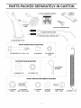
PARTS PACKED SEPARATELY I
(1) FUEL STABiLiZER
CARTON
(1) MULTi=
WRENCH
PACKET
(1) POWER
CORD
(2) SAFETY iGNiTiON
(1) AUGER CONTROL
KEYS
ROD
1111111
(1) TRACTION DRIVE CONTROL
(1) DISCHARGE
ROD
CHUTE
EXTRA
SHEAR
DOLTS
AND NUTS
©
(2) SHEAR BOLTS
1/4=20 x %3/4
ROTATOR
HEAD
(2) SPACERS
(2) LOCKNUTS
1/4=20
MOUNTING
(3) RETAINER
SPRINGS
(1) WASHER
3/8
(1) LOCKNUT
CHUTE
(1) LOCKNUT
5/16=18
(1) CARRIAGE
BOLT 5/16=18 x 5/8
3/8
DEFLECTOR
(1) LOCKNUT
1/4-20
REMOTE
CONTROL
(1) NYLON
WASHER
{1) SHOULDER
BOLT 1/4=20
(1)
AS
/
Read these instructions and this manual in its entirety
before you attempt to assemble or operate your new
snow thrower. Reading the entire manual will familiar=
ize you with the unit, which will assist you in assembly,
operation and maintenance of the product.
Your new snow thrower has been assembled at the factory
with the exception of those parts left unassembled for shipping purposes. All parts such as nuts, washers, bolts, etc.,
necessary to complete the assembly have been placed in
the parts bag. To ensure safe and proper operation of your
snow thrower, all parts and hardware you assemble must
be tightened securely. Use the correct tools as necessary
to ensure proper tightness.
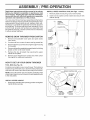
REMOVE
SNOW THROWER
FROM CARTON
1.
Remove all accessible loose parts and parts boxes
from carton.
2.
Cut down all four corners of carton and lay panels flat.
3.
Remove the two (2) screws securing the auger housing
to the pallet.
4.
Remove all packing materials except plastic tie holding
speed control rod to lower handle.
5.
Remove the two (2) plastic ties securing the upper
handle to the pallet.
Remove snow thrower from carton and check carton
thoroughly for additional loose parts.
6.
RE-O
ERATION
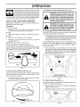
INSTALL SPEED CONTROL ROD (See Figs. 1 and 2)
1.
Remove plastic tie securing rod to lower handle.
2.
insert rod into speed control bracket and secure with
retainer spring.
SPEED
CONTROL
ROD
PLASTIC
//
/ /
/ /
TIE
UPPER
HANDLE
i
HANDLE
KNOB
LOWER
HANDLE
J
HOW TO SET UP YOUR SNOW THROWER
TOOL BOX (See Fig, 10)
A toolbox is provided on your snow thrower. The toolbox is
located on top of the belt cover. Store the extra shear bolts,
nuts and multi-wrench provided in parts bag in the toolbox.
FIG. 1
SPEED CONTROL
NOTE: The multi-wrench may be used for assembly of the
chute rotator head to snow thrower and making adjustments
to the skid plates.
RETAINER
SPRING
UNFOLD UPPER HANDLE
1.
Raise upper handle to the operating position and tighten
handle knobs securely.
SPEED
CONTROL
BRACKET
SPEED
CONTROL
LEVER
FIG. 2
ROD
AS
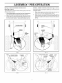
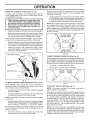
INSTALL TRACTION
/
DRIVE CONTROL ROD
(See Figs. 3 and 4)
The traction drive control rod has the long loop on the end
of the spring as shown.
1.
Slide rubber sleeve up rod and hook end of spring into
pivot bracket with loop opening down as shown.
2.
With top end of rod positioned under left side of control
panel, push rod down and insert top end of rod into hole
in drive control bracket. Secure with retainer spring.
RE-O
ERATION
INSTALL AUGER CONTROL ROD (See Figs. 5 and 6)
The auger control rod has the short loop on the end of the
spring as shown.
1.
Slide rubber sleeve up rod and hook end of spring into
control arm with loop opening up as shown.
2.
With top end of rod positioned under right side of
control panel, push down on rod and insert end of rod
into hole in auger control bracket. Secure with retainer
spring.
AUGER
ROD
RUBBER
SLEEVE
LOOP
OPENING
DOWN
FIG. 3
CONTROL
ARM
FIG. 5
RETAINER
SPRING
AUGER CONTROL
ROD
RETAINER
SPRING
CONTROL
BRACKET
AUGER
CONTROL
LEVER
\
CONTROL
BRACKET
FIG, 4
FIG. 6
AS
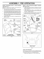
iNSTALL DISCHARGE
HEAD (See Fig. 7)
CHUTE
BLY /
/ CHUTE
ROTATER
NOTE: The multi-wrench provided in your parts bag may
be used to install the chute rotater head,
1,
2,
3,
4,
Place discharge chute assembly on top of chute base
with discharge opening toward front of snow thrower,
Position chute rotater head overchute bracket, If necessary, rotate chute assembly to align square and pin on underside of chute rotater head with holes in chute bracket,
RE-O
ERATION
iNSTALL
CHUTE
DEFLECTOR
REMOTE
CONTROL
(See Figs. 8 and 9)
1, Install remote cable bracket to discharge chute with
5/16-18 carriage bolt and 5/16-18 Iocknut as shown,
Tighten securely,
2,
Install remote cable eyelet to chute deflector with
1/4-20 shoulder bolt, nylon washer and 1/4-20 Iocknut
as shown, Tighten securely,
3,
Install spring hooks between hex nuts on chute rotater
head and into hole in chute deflector as shown,
With chute rotater head and chute bracket aligned,
position chute rotater head on pin and threaded stud
of mounting bracket,
SPRING
1/4-20
SHOULDER
Install 3/8 washer and Iocknut on threaded stud and
tighten securely,
CHUTE
HOOK
BETWEEN
HEX NUTS
ON CHUTE
ROTATER
NYLON
WASHER
CHUTE
ROTATER
1/4-20
LOCKNUT
5/16- ! 8
CARRIAGE
BOLT
CABLE
EYELET
_B
_EMOTE
CABLE
RACKET
PIN
5/16-18
LOCKNUT
STUD
FiG. 8
ROTATER HEAD
MOUNTING
BRACKET
FIG. 7
//
//
CHUTE DEFLECTOR
CONTROL LEVER
FIG. 9
CHECK TiRE PRESSURE
The tires on you r snow th rower were overinflated at the factory for shipping purposes. Correct and equal tire pressure
is important for best snow throwing performance,
•
Reduce tire pressure to 14-17 PSi (19-24,5 N-m),
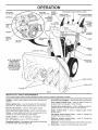
OPERATION
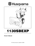
KNOW YOUR SNOW THROWER
READ THIS OWNER'S MANUALAND ALL SAFETY RULES BEFORE OPERATING YOUR SNOWTHROWER.
Compare
the illustrations with your snow thrower to familiarize yourself with the location of various controls and adjustments, Save
this manual for future reference,
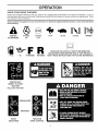
These symbols may appear on your snow thrower or in literature supplied with the product. Learn and understand
their
meaning,
I\1
DANGER
OR WARNING
ENGINE
ON
ENGINE
OFF
R
FUEL
OIL
FORWARD
REVERSE
IGNITION KEY.
INSERT TO START
AND RUN,
PULL OUT TO STOP.
DISENGAGED
ENGAGED
\
J
SNOW
DISCHARGE
_J
TRACTION
DRIVE CONTROL
FAST
SLOW
CHOKE
PRIMER
READ AND FOLLOW ALL SAFETY INFORMATION
AND INSTRUCTIONS BEFORE USE OF THIS PRODUCT.
KEEP THESE INSTRUCTIONS
FOR FUTURE REFERENCE.
O ERATION
GASOLINE
ELECTRIC
START BUTTON
AUGER
CONTROL
LEVER
RECOIL
STARTER
HANDLE
X
\
DISCHARGE
DRIVE SPEED
CONTROL
LEVER
LEVER
DEFLECTOR
REMOTE
CONTROL
LEVER
' TRACTION
DRIVE
CONTROL
LEVER
CHUTE
DEFLECTOR
CHOKE
CONTROL
CHUTE CONTROL
_HTURN
TRIGGER
SAFETY
IGNITION
KEY
LIGHT
CHUTE
ON / OFF
SWITCH
HANDLE
KNOB
CLEAN-OUT
TOOL
i
TOOLBOX
NOTE: ITEMS ABOVE
ARE SHOWN IN
THEIR TYPICAL
LOCATION ON THE
ENGINE. ACTUAL
LOCATION MAY VARY
WITH THE ENGINE
ON YOUR UNIT.
\
CONTROL
DRIFT CUTTER
PLATE
FIG. 10
MEETS A,N,S,I, SAFETY REQUIREMENTS
Our snow throwers conform to the standards of the American National Standards Institute,
Toolbox = used to store spare shear bolts, Iocknuts and
wrench,
Safety ignition key - must be inserted for the engine to
start and run, Remove when snow thrower is not in use,
Electric
start button - used for starting the engine,
Recoil (auxiliary) starter handle-
used for starting engine,
Primer - pumps additional fuel from the carburetor to the
cylinder for use when starting a cold engine,
Choke Control - used for starting a cold engine,
ON / OFF switch =used to STOP the engine,
Freewheel control - disengages transmission for pushing
the snowthrower with the engine off,
LH and RH turn triggers - used to steer the snow thrower,
Drive speed control lever - used to select forward or
reverse motion and speed of snow thrower,
Traction drive control lever- used to engage power-propelled forward or reverse motion of snow thrower,
Auger control
(throw snow),
lever - used to engage auger motion
Discharge chute control lever - used to change the
direction the snow is thrown,
Deflector remote control lever - used to change the
distance the snow is thrown,
Skid plate - used to adjust height of scraper barfrom ground,
10 Drift cutter - used to cut through deep snowdrifts,
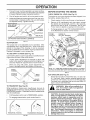
OPERATION
The operation of any snow thrower can result
in foreign objects thrown into the eyes, which
can result in severe eye damage. Always wear
safety glasses or eye shields while operating
your snow thrower or performing any adjustments or repairs. We recommend standard safety glasses
or a wide vision safety mask worn over spectacles.
HOW TO USE YOUR
TO CONTROL SNOW DISCHARGE
WARNING: Snow throwers have exposed rotating parts, which can cause
terial thrown from the discharge chute.
severe injuryfrom contact, or from maKeep the area of operation clear of all
persons, small children and pets at all
times including startup.
SNOW THROWER
Know how to operate all controls before adding fuel or
attempting to start the engine.
STOPPING
TRACTION DRIVE
•
Release traction drive control lever to stop the forward
or reverse movement of the snow thrower.
AUGER
WARNING: If the discharge chute or auand wait for all moving parts to stop. Use
get
become clogged,
engine
the clean=out
tool, NOTshut-off
YOUR HANDS,
to unclog the chute and/or auger.
The DIRECTION in which snow isto be thrown is controlled
by the discharge chute control lever.
•
Release the auger control lever to stop throwing snow.
ENGINE
1.
Move ON / OFF switch to "OFF" position.
2.
Remove (do not turn) safety ignition key to prevent
unauthorized use.
(See Fig. 13)
•
Tochangethe discharge chute position, press downward
on discharge chute control lever and move lever left
or right until chute is in desired position. Be sure lever
springs back and locks into desired position.
The DISTANCE that snow is thrown is controlled by the
position of the chute deflector. Set the deflector low to
throw snow a short distance; set the deflector higher to
throw snow farther.
NOTE: Never use choke to stop engine.
TO USE THROTTLE CONTROL (See Fig. 11)
The throttle control is located on the engine. Always operate
the snow thrower with the engine at full throttle. Full throttle
offers the best snow thrower performance.
Press downward on chute deflector control lever and
move lever forward to lower the deflector and decrease
the distance. Move lever back to raise the deflector
and increase the distance. Be sure lever springs back
and locks into desired position.
DISCHARGECHUTE
CONTROLLEVER
(,
)
SLOW
FAST
FIG, 11
TO USE CHOKE CONTROL (See Fig. 12)
The choke control is located on the engine. Use the choke
control whenever you are starting a cold engine. Do not
use to start a warm engine.
•
To engage choke, turn knob counterclockwise.
turn knob clockwise to disengage.
CHUTE DEFLECTOR
REMOTE CONTROLLEVER
Slowly
FIG, 13
TO THROW SNOW (See Fig. 14)
The auger rotation is controlled by the auger control lever
located on the right side handle.
(
OFF
FIG. 12
•
Squeeze auger control lever to handle to engage the
auger and throw snow.
•
Release the auger control lever to stop throwing snow.
I\l FULL
11
FIG. 14
OPERATION
Reverse ground speed will increase as the lever is pulled
backward, allowing the operator to vary the speed of the
unit while it is moving.
USING THE CLEAN-OUT TOOL (See Fig. 15)
in certain snow conditions, the discharge chute may become clogged with ice and snow. Use the clean-out tool
to dislodge this blockage.
•
When cleaning, repairing, or inspecting, make
certain all controls are disengaged and the au=
get/impeller and all moving parts have stopped.
Disconnect the spark plug wire and keep the
wire away from the spark plug to prevent accidental starting.
NOTE: When both traction drive and auger control levers
are engaged, the traction drive control lever will lock the
auger control lever in the engaged position. This will allow
you to release your right hand from the handle and adjust
the discharge chute direction without interrupting the snow
throwing process.
Release the auger control lever and shut offthe engine.
•
Slower speeds are for heavier snow and faster speeds
are for light snow and transporting the snow thrower. It
is recommended that you use a slower speed until you
are familiar with the operation of the snow thrower.
Removethe clean-out tool from it's mounting clip. Grasp
the tool firmly by the handle and push and twist the tool
into the discharge chute to dislodge the blockage.
TRACTION
After the packed snow has been dislodged, return the cleanout tool to it's mounting clip by pushing it into the clip.
.
Make surethe discharge chute is pointed in asafe direction (no vehicles, buildings, people, or other objects are
in the direction of discharge) before restarting the engine.
•
Restart the engine, then squeeze the auger control
lever to the handle to clear snow from the auger housing and the discharge chute.
l
DRIVE
LEVER
DRIVE SPEED
CONTROLLEVER
1
FIG. 16
DISCHARGECHUTE
POWER STEERING OPERATION (See Fig. 17)
Steering triggers are usedtoassist insteering yoursnowthrower. The triggers are located on the underside of each handle.
When atrigger is squeezed, itdisengages the drive wheel on
that side of snowthrower and allows ittoturn in that direction,
TOOL
MOUNTING
•
To turn left- squeeze left side trigger,
•
To turn right - squeeze right side trigger,
TURN
FIG, 15
TO MOVE FORWARD AND BACKWARD
(See Fig. 16)
FIG. 17
SELF-PROPELLING, forward and reverse movement of
the snow thrower, is controlled by the traction drive control
lever located on the left side handle.
•
Squeeze traction drive control lever to handle to engage
the drive system,
•
Release traction drive control lever to stop the forward
or reverse movement of the snow thrower,
TO ADJUST SKiD PLATES (See Fig. 17)
NOTE: The wrench provided in your parts bag may be
used to adjust the skid plates.
Skid plates are located on each side of the auger housing
and adjust the clearance between the scraper bar and the
ground surface. Adjust skid plates evenly to proper height
for current surface conditions. For removal of snow in
normal conditions, such as a paved driveway or sidewalk,
place skid plates in the highest position (lowest scraper
clearance) to give a 1/8" clearance between the scraper
bar and the ground. Use a middle position if the surface
to be cleared is uneven.
SPEED and DIRECTION are controlled by the drive speed
control lever.
•
Squeeze traction drive control lever to handle to engage
the drive system, then slowly move drive speed control
lever to desired "FORWARD" or "REVERSE" setting,
Forward ground speed will increase as the lever is moved
forward, allowing the operator to vary the speed of the unit
while it is moving,
•
NOTE: It is not recommended to operate the snow thrower
over gravel or rocky surfaces. Objects such as gravel, rocks
or other debris, can easily be picked up and thrown by the
impeller, which can cause serious personal injury, property
damage or damage to the snow thrower.
To reverse direction, slowly pull lever back until snow
thrower stops, then pull lever further back,
12
OPERATION
•
If snow thrower must be operated over gravel surface,
use extra caution and be sure skid plates are adjusted
to lowest (highest scraper clearance) position.
BEFORE
1.
Shut off engine and wait for all moving parts to stop.
2.
Adjust skid plates by loosening the hex nuts, then moving skid plate to desired position. Be sure both plates
are adjusted evenly. Tighten securely.
The engine on your snow thrower has been shipped, from
the factory, already filled with oil.
STARTING
THE ENGINE
CHECK ENGINE OiL LEVEL (See Fig. 21)
1.
Check engine oil with snow thrower on level ground.
2.
Remove oil fill cap/dipstick and wipe clean, reinsert
the dipstick and screw tight, wait for a few seconds,
remove and read oil level. If necessary, add oil until
"FULE' mark on dipstick is reached. Do not overfill.
•
To change engine oil, see "TO CHANGE ENGINE OIE'
in the Maintenance section of this manual.
(LOW GROUND
CHOKE
CONTROL
ENGINE OIL
FILL CAP / DIPSTICK
GASOLINE
FILLER CAP
\
FIG, 17
STARTER
BUTTON
SCRAPER BAR
The scraper bar is not adjustable, but is reversible. After
considerable use it may become worn. When it has worn
almost to the edge of the housing, it can be reversed,
providing additional service before requiring replacement.
Replace a damaged or worn scraper bar.
TO USE DRIFT CUTTERS (See Fig. 19)
Use the drift cutters to cut through deep snowdrifts that are
higher than the front of the snow thrower.
•
Loosen upper adjustment nut enough to allow drift
cutter to be raised to highest position and tighten nut
securely. Repeat for opposite side of snow thrower.
PRIMER
•
When not using drift cutters, loosen adjustment nut,
lower to storage position and tighten nut securely.
IGNITION
KEY
SAFETY
FIG. 21
STORAGE_
POSITION
DRIFT
CUTTER
/
ADD GASOLINE (See Fig. 21)
•
Fill fuel tank to bottom of tank filler neck. Do not overfill. Use fresh, clean, regular unleaded gasoline with
a minimum of 87 octane. Do not mix oil with gasoline.
Purchase fuel in quantities that can be used within 30
days to assure fuel freshness.
ADJUSTMENT NUT
FIG, 19
(See Fig, 20)
fuel,
Do not store,
spillany
or use
gasoline
WARNING:
Wipe off
spilled
oil or
near an open flame.
When pushing or towing your snowthrower, be sure to
disengage transmission by placing freewheel control into
FREEWHEEL position. Freewheel control is located atthe
rear of snowthrower.
•
Pull freewheel control out to FREEWHEEL position.
•
To reengage transmission, push control back in.
CAUTION: Alcohol blended fuels (called gasohol or using ethanol or methanol) can attract
moisture which leads to separation and for=
mation of acids during storage. Acidic gas can
damage the fuel system of an engine while in
storage. To avoid engine problems, the fuel
system should be emptied before storage of
30 days or longer. Empty the gas tank, start
the engine and let it run until the fuel lines and
carburetor are empty. Use fresh fuel next season. See Storage instructions
for additional
information. Never use engine or carburetor
cleaner products in the fuel tank or permanent
damage may occur.
\
FREEWHEEL
ON/OFF
SWITCH
NOTE: ALL iTEMS ARE SHOWN IN THEIR TYPICAL LOCATION.
ACTUAL LOCATION MAY VARY WITH ENGINE ON YOUR UNIT.
AUGER
HOUSING
TO TRANSPORT
RECOIL
STARTER
HANDLE
POSITION
TRANSMISSION
FIG, 20
ENGAGED
13
OPERATION
TO START ENGINE
WARM START-
Your snow thrower engine is equipped with both a 120 Volt
A.C. electric starter and a recoil starter. The electric starter
is equipped with a three-wire power cord and plug and is
designed to operate on 120 Volt A.C. household current.
Follow the steps above, keeping the choke in the "OFF"
position. DO NOT push the primer.
BEFORE STOPPING
Run the engine for a few minutes to help dry off any moisture on the engine.
•
Be sure your house is a 120 Volt A.C. three-wire
grounded system.
If you are uncertain, consult a
licensed electrician.
WARNING:
Do not use the
A.C.
three=wire
starter
if your
rious personal
snow thrower
electric
grounded
system.
Se=
house
is not
a 120 Volt
injury or damage to your
could result.
COLD START - ELECTRIC STARTER
1.
Insert safety ignition key (packed separately in parts
bag) into ignition slot until it clicks. DO NOTturn the key.
Keep the extra safety ignition key in a safe place.
2. Place ON / OFF switch in "ON" position.
3. Rotate choke control to "FULL:.'position.
4. Connect the power cord to the engine.
5. Plug the other end of the power cord into a three-hole
grounded 120 Volt A.C. receptacle.
NOTE: Do not use primer when starting engine with the
electric starter.
6. Push starter button until engine starts.
IMPORTANT: Do not crank engine more than five continuous seconds between each time you try to start. Wait
5 to 10 seconds between each attempt.
7. When the engine starts, release the starter button and
slowly move the choke control to the "OFF" position.
8. Disconnect the power cord from the receptacle first,
then from the engine.
Allow the engine to warm up for a few minutes. Engine will
not develop full power until it has reached normal operating temperature.
WARM START - ELECTRIC STARTER
Follow the steps above, keeping the choke control in the
"OFF" position.
COLD START- RECOIL STARTER
1. Insert safety ignition key (packed separately in parts
bag) into ignition slot until it clicks. DO NOTtum the key.
Keep the extra safety ignition key in a safe place.
2. Place ON / OFF switch in "ON" position.
3. Rotate choke control to "FULE' position.
4. Push the primer four (4) times if the temperature is
below 15°F, or two (2) times if temperature is between
15 ° and 50°R If temperature is above 50°F, priming is
not necessary.
NOTE: Over priming may cause flooding, preventing the
engine from starting. If you do flood the engine, wait a few
minutes before attempting to start and DO NOT push the
primer.
5. Pull recoil starter handle quickly. Do not allow starter
rope to snap back.
6. When the engine starts, release the recoil starter handle
and slowly move the choke control to the "OFF" position.
Allow the engine to warm up for a few minutes. Engine will
not develop full power until it has reached normal operating temperature.
14
RECOIL STARTER
IF RECOIL STARTER HAS FROZEN
If the recoil starter has frozen and will not turn the engine,
proceed as follows:
1.
Grasp the recoil starter handle and slowly pull as much
rope out of the starter as possible.
2.
Release the recoil starter handle and let it snap back
against the starter.
If the engine still fails to start, repeat the above steps or
use the electric starter.
SNOW THROWING
o
o
TiPS
Go slower in deep, freezing or heavy wet snow. Use
the drive speed control, NOT the ON / OFF switch, to
adjust speed.
It is easier and more efficient to remove snow immediately after it falls,
The best time to remove snow is the early morning. At
this time the snow is usually dry and has not been exposed to the direct sun and warming temperatures,
Slightly overlap each successive
snow will be removed,
path to ensure all
Throw snow downwind whenever possible.
Adjust the skid plates to proper height for current snow
conditions. See "TO ADJUST SKID PLATES" in this
section of this manual.
•
For extremely heavy snow, reduce the width of snow
removal by overlapping previous path and moving
slowly.
•
Keep engine clean and clear of snow during use. This
will help air flow and extend engine life.
•
After snow-throwing is completed, allow engine to run for
a few minutes to melt snow and ice off the engine.
•
Clean the entire snow thrower thoroughly after each
use and wipe dry so it is ready for next use.
thrower if weather conditions impair vis=
WARNING:
Do snow
not during
operatea heavy,
snow
ibility. Throwing
windy snowstorm can blind you and be
hazardous to the safe operation of the
snow thrower.
CE
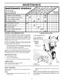
MAINTENANCE
SCHEDULE
J_£_,4"._0_
AS YOU COMPLETE
REGULAR
SERVICE
f_y_'_r_/'_'4r/_fb_
Check for Loose Fasteners
R
0
W
Lubrication
E
N
DATES
I_
Clean / Inspect Snow Thrower
Check/Replace
SERVICE
I_
I_
if
V=Beks
I_
Chart
!_
if
Check Engine Oil Level
Change
v'
Engine Oil
v'
Inspect Muffler
N
E
Check / Replace
v'
Spark Plug
v'
Empty Fuel Tank
GENERAL
RECOMMENDATIONS
LUBRICATION
The warranty on this snow thrower does not cover items
that have been subjected to operator abuse or negligence.
To receive full value from the warranty, operator must
maintain snow thrower as instructed in this manual. Some
adjustments will need to be made periodically to properly
maintain your snow thrower.
(_ SAE 5W=30 Motor Oil
(_ General
At least once a season, check to see if you should make
any of the adjustments described in the Service and Adjustments section of this manual.
•
•
CHART
Purpose
Grease
At least once a year, you should replace the spark plug
and check belts for wear. A new spark plug will help
your engine run better and last longer.
Follow the maintenance schedule in this manual.
@ Engine oil
NOTE: Use only Original Equipment Manufacturer (OEM)
parts to service this unit. Failure to do so can cause the unit
to malfunction and pose a risk of injury to the operator.
BEFORE
EACH
USE
1.
2.
Check engine oil level.
Check for loose fasteners.
3,
Check controls to be sure they are functioning properly.
Pivot
points
LUBRICATION
Keep your snow thrower well lubricated
(See "LUBRICATION CHART"),
Auger
grease fittings
SNOW THROWER
any
Keep tires free of gasoline and oil, which can harm
rubber.
Maintain proper air pressure in both tires (14-17 RS.I.
/ 19-24.5 N-m).
NOTE: To seal tire punctures and prevent flat tires due
to slow leaks, tire sealant may be purchased from your
local parts dealer. Tire sealant also prevents tire dry rot
and corrosion.
Always observe the safety rules when performing
maintenance.
TIRES
•
15
E
V-BELTS
TO CHANGE ENGINE OIL
Check V-belts for deterioration and wear after every 50
hours of operation and replace if necessary. The belts
are not adjustable. Replace belts if they begin to slip from
wear. (See "TO REMOVE BELT COVER" in the Service
and Adjustments section of this manual).
Determine temperature range anticipated before next oil
change. All oil must meet API service classification SG-SL.
•
Be sure snow thrower is on level surface.
•
Oil will drain more freely when warm.
•
Catch oil in a suitable container.
The V-belts on your snow thrower are of special construction
and should be replaced by original equipment manufacturer
(OEM) belts available from your nearest dealer. Using other
than OEM belts can cause personal injury or damage to
the snow thrower.
NOTE: The left side wheel may be removed from snow
thrower for easier access to the oil drain plug and placement of a suitable container. The unit tilted, resting on the
frame with the left wheel removed, will help drain any oil
trapped inside the engine. (See "TO REMOVE WHEELS"
in the Service and Adjustments section of this manual).
AUGER GEAR CASE
1.
Remove safety ignition key and disconnect spark plug
wire from spark plug. Place wire where it cannot come
in contact with plug.
2.
Clean area around drain plug.
3.
Remove drain plug and drain oil in a suitable container.
4.
Install drain plug and tighten securely.
DO NOT lubricate the drive components inside the snow
thrower. The sprockets, hex shafts, drive disc and friction
wheel require no lubrication. The bearings and bushings
are lifetime lubricated and require no maintenance.
5.
Wipe off any spilled oil from snow thrower and engine.
6.
Install left wheel (if removed for draining oil). Be sure to
install klick pin into proper hole in wheel axle (See "TO
REMOVE WHEELS" in the Service and Adjustments
section of this manual).
CAUTION: Any lubricating of the above compo=
nents can cause contamination of the friction
wheel and damage to the drive system of your
snow thrower.
7.
Remove oil fill cap/dipstick.
to enter the engine.
8.
Refill engine with oil through oil dipstick tube. Pour
slowly. Do not overfill. For approximate capacity see
"PRODUCT SPECI FICATIO NS" section of this manual.
9.
Use gauge on oil fill cap/dipstick for checking level.
Be sure dipstick cap is tightened securely for accurate
reading. Keep oil at "FULL.' line on dipstick.
•
•
The gear case was filled with lubricant to the proper
level at the factory. The only time the lubricant needs
attention is if service has been performed on the gear
case.
If lubricant is required, use only Ronex ED #1 grease.
TRACTION
DRIVE SYSTEM
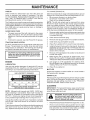
ENGINE
LUBRiCATiON
Use only high quality detergent oil rated with API service
classification SG-SL Select the oil's SAE viscosity grade
according to your expected operating temperature.
SAE VISCOSITY
Be careful not to allow dirt
10. Wipe off any spilled oil.
MUFFLER
Inspect and replace corroded muffler as it could create a
fire hazard and/or damage.
GRADES
SPARK PLUG
°F
i°C
-20
-3'0
0
-20
30
=1'0
32
Replace spark plug at the beginning of each season or after
every 100 hours of operation, which ever occurs first. Spark
plug type and gap setting are shown in the "PRODUCT
SPECIFICATIONS" section of this manual.
40
0
10
CLEANING
TEMPERATURE RANGE ANTICIPATED
BEFORE NEXT OiL CHANGE
iMPORTANT: For best performance, keep snow thrower
housing free of any dirt or trash, Clean the outside of your
snow thrower after each use.
NOTE: Although multi-viscosity oils (5W30, 10W30 etc.)
improve starting in cold weather, these multi-viscosity oils
will result in increased oil consumption when used above
32°F/0°C. Check your engine oil level more frequently to
avoid possible engine damage from running low on oil.
and disconnect spark plug wire from
WARNING:
spark plug, Removesafetyignitionkey
Place wire where it cannot
come in contact with plug.
Change the oil after every 25 hours of operation or at least
once a year if the snow thrower is not used for 25 hours
in one year.
Keep finished surfaces/wheels free of gasoline, oil, etc.
We do not recommend using a garden hose to clean
your snow thrower unless the electrical system, muffler
and carburetor are covered to keep water out. Water
in engine can result in shortened engine life.
Check the crankcase oil level before starting the engine and
after each five (5) hours of continuous use. Tighten oil fill
cap / dipstick securely each time you check the oil level.
16
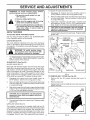
SERVICE
WARNING:
performing
To avoid serious injury,
any service or adjustments:
ADJUSTMENTS
To replace the capscrew/shear
before
1. Be sure the on/off switch is in the
OFF position.
1.
Disengage all controls and move throttle control to
STOP position. Wait for all moving parts to stop.
2.
Remove safety ignition key and disconnect spark plug
wire from spark plug. Place wire where it cannot come
in contact with plug.
3.
Align holes in impeller hub with holes in impeller shaft
and install two (2) new 1/4-20 x 1-5/8" capscrew/shear
bolts. Install 1/4-20 Iocknuts and tighten securely.
4.
Connect spark plug wire to spark plug. Replace safety
ignition key.
2. Remove safety ignition key.
3. Make
sure the
augers and
all moving
parts have
completely
stopped.
4. Remove safety ignition keyanddiscon=
nect spark plug wire from spark plug.
Place wire where it cannot come in
contact with plug_
SNOW THROWER
TO ADJUST SNOW THROWER HEIGHT
See "TO ADJUST SKID PLATES" and "SCRAPER
in the Operation section of this manual.
BAR"
1/4-20
LOCKNUT
\
CHUTE DEFLECTOR
The chute deflector, attached to the top of the discharge
chute, is provided to direct discharging snow away from
the operator. If the deflector becomes damaged, it should
be replaced.
I
•
&
bolts:
\
/_'_
_._
//7_f
_///
1/4-20 × 1-5/8
_CAPSCREW/
SHEAR BOLT
IMPELLER
HUB
1/4-20 x 2
_
SHOULDER /
_il/SHEAR
BOLT
_
sPAcER
WARNING: To avoid serious injury,
never operate your snow thrower with
the deflector removed or damaged.
To change direction and/or distance snow is discharged,
see "TO CONTROL SNOW DISCHARGE" in the Operation section of this manual.
SHEAR BOLTS (See Fig, 22)
AUGER SHEAR BOLTS
Both right and left-hand augers are secured to the auger
shaft with a shoulder/shear bolt and hex nut. Should a foreign object or ice become lodged in the augers, the shear
bolts are designed to break, preventing damage to any
other components. If one or both augers do not turn when
auger control lever is engaged, check to see if one or both
of the bolts have sheared. To replace the shear bolts:
1.
Disengage all controls and move throttle control to
STOP position. Wait for all moving parts to stop.
2.
Remove safety ignition key and disconnect spark plug
wire from spark plug. Place wire where it cannot come
in contact with plug.
3.
I
FIG, 21
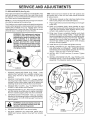
TO REMOVE BELT COVER (See Fig. 23)
1. Remove the two (2) screws securing belt cover to
frame.
2.
Remove belt cover.
•
Replace belt cover by installing cover and screws and
tighten securely.
Align hole in auger hub with hole in auger shaft and install
a new 1/4-20 x 2" shoulder/shear bolt and spacer. Install
1/4-20 lock nut and tighten securely.
BELT
COVER
CAUTION: Do not substitute. Use only original
equipment shear bolts as supplied with your
snow thrower.
4.
Connect spark plug wire to spark plug. Replace safety
ignition key.
IMPELLER SHEAR BOLTS
The impeller is secured to the impeller shaft with two (2)
capscrew/shear bolts and hex nuts. Should a foreign object
or ice become lodged in the impeller, the capscrews are
designed to break, preventing damage to any other components. If impeller does not turn when auger control lever
is engaged, check to see if the capscrews have sheared.
SCREWS
17
FIG.23
SERVICE
ADJUSTMENTS
TO REPLACE BELTS (See Fig. 24)
The auger and traction drive belts are not adjustable. If the
belts are damaged or begin to slip from wear, they should
be replaced. It is recommended that the belt(s) be replaced
by a Sears service centre/department.
HINT: Insert a 3/8" drive ratchet (in the "ON" position) into
the square hole in idler arm and rotate ratchet clockwise
to relieve tension,
8.
NOTE: It is recommended that both the auger and traction
drive belt be replaced at the same time.
With tension relieved on idler, install new traction drive
belt around pulleys and inside belt keepers.
9.
The V-belts on your snow thrower are of special construction
and should be replaced by original equipment manufacturer
(OEM) belts available from your nearest Sears service
centre/department. Using other than OEM belts can cause
)ersonal injury or damage to the snow thrower.
Place auger belt around and inside the groove of auger
pulley only.
10. While your assistant slowly raises handles to rejoin
the auger housing and frame assembly, pull up on the
auger belt and squeeze sides together above pulley
so belt is fully seated in groove of pulley.
&
FRAME
ASSEMBLY
11. Bring snow thrower completely together and check
carefully for proper routing of belts. If auger belt has
become dislodged from the pulley (by catching the idler
arm bracket while bringing snow thrower together),
separate the snow thrower and repeat step 10. Belt
must be fully seated in pulley groove when bringing
the snow thrower together.
WARNING: Belt replacement requires
separation of the snow thrower, While
separating the auger housing from the
frame assembly, it is important that
an assistant stand in the operating
position and hold the snow thrower
handles, Serious personal injuryand/or
damage to the unit couJd occur if the
snow thrower shouJd falJ during the belt
changing process.
12. Install the two (2) hex bolts and tighten securely.
13. INSTALL ENGINE PULLEY- Place belt in pulleygroove
and slide pulley on crankshaft,
Install flat washer,
Iockwasher and bolt and tighten securely (41-47 N-m
torque), Make sure belt is inside belt keeper,
AUGER
HOUSING
14, INSTALL
securely,
15, INSTALL
CHARGE
Assembly
1.
2.
3.
REMOVE ENGINE PULLEY-Removebolt, lockwasher
and flat washer securing pulley to engine crankshaft.
Remove outside (auger) pulley only from crankshaft.
5.
SEPARATE SNOW THROWER - With your assistant
standing in the operating position holding the handles,
remove the two (2) bolts holding auger housing and
frame together.
i•
/"
_
7.
DISCHARGE CHUTE - See "INSTALL DISCHUTE / CHUTE ROTATER HEAD" in the
/ Pre-Operation section of this manual,
REMOVE GASOLINE FROM FUEL TANK - Drain
gasoline from fuel tank into a suitable container, outdoors, away from fire or flame. Wipe up any spilled
gasoline.
REMOVE DISCHARGE CHUTE - Loosen Iocknut
securing chute rotator head to mounting bracket only
enough to allow chute rotator head to be raised and
discharge chute to be removed from snow thrower.
REMOVE BELT COVER - See "TO REMOVE BELT
COVER" in this section of this manual.
4.
6,
BELT COVER and two (2) screws, Tighten
REMOVE AUGER BELT from around pulley.
RELIEVE TENSION ON TRACTION DRIVE BELT
IDLER and remove traction drive belt from around
pulleys.
FRAME
18
I
//
AUGER
HOUSING
TO REMOVE WHEELS (See Fig. 25)
•
Remove the klik pin and remove wheel from axle.
IMPORTANT: When installing wheel, be sure to use the
axle hole closest to the end of the shaft - do not use the
hole in the wheel hub (if equipped). Inner hole in axle and
hole in wheel hub are not used for your model snow thrower.
OUTER HOLE
KLIK PIN (INSTALL
IN OUTER HOLE
OF AXLE ONLY)
NOTE: To seal punctures or prevent flat tires due to slow
leaks, tire sealant may be purchased from your local parts
dealer. Tire sealant also prevents tire dry rot and corrosion,
ENGINE
CARBURETOR
Your carburetor is not adjustable. Engine performance
should not be affected at altitudes up to 2,134 meters. If
your engine does not operate properly due to suspected
carburetor problems, take your snow thrower to a Sears
service centre/department.
ENGINE SPEED
AXLE
WHEEL
WHEEL HUB
FIG, 25
Never tamper with the engine governor, which is factory set
for proper engine speed. Overspeeding the engine above
the factory high speed setting can be dangerous and will
void the warranty. If you think the engine-governed high
speed needs adjusting, contact a Sears service centre/department, which has the proper equipment and experience
to make any necessary adjustments.
STO
Immediately prepare your snow thrower for storage at
the end of the season or if the unit will not be used for 30
days or more.
WARNING:
Never store the snow
thrower with gasoline in the tank inside
open
flame,where
spark fumes
or pilotmay
lightreach
as onana
a building
furnace, water heater, clothes dryer or
gas appliance, Allow the engine to cool
before storing in any enclosure.
SNOW THROWER
When snow thrower is to be stored for a period of time,
clean it thoroughly, remove all dirt, grease, leaves, etc,
Store in a clean, dry area.
1,
2.
3,
Clean entire snow thrower (See "CLEANING"
Maintenance section of this manual).
in the
Inspect and replace belts, if necessary (See "TO REPLACE BELTS" in the Service and Adjustments section
of this manual).
Lubricate as shown in the Maintenance section of this
manual.
4.
Be surethat all nuts, bolts, screws, and pins are securely
fastened. Inspect moving parts for damage, breakage
and wear. Replace if necessary.
5.
Touch up all rusted or chipped paint surfaces; sand
lightly before painting.
ENGINE
E
•
Empty the fuel tank by starting the engine and letting
it run until the fuel lines and carburetor are empty.
•
Never use engine or carburetor cleaner products in
the fuel tank or permanent damage may occur.
Use fresh fuel next season.
•
NOTE: Fuel stabilizer is an acceptable alternative in minimizing the formation of fuel gum deposits during storage.
Add stabilizer to gasoline in fuel tank or storage container.
Always follow the mix ratio found on stabilizer container.
Run engine at least 10 minutes after adding stabilizer to
allow the stabilizer to reach the carburetor. Do not empty
the gas tank and carburetor if using fuel stabilizer.
ENGINE OiL
Drain oil (with engine warm) and replace with clean engine
oil. (See "ENGINE" in the Maintenance section of this
manual).
CYLINDER
1.
Remove spark plug.
2.
Pour approximately one ounce (30 ml) of oil through
spark plug hole into cylinder.
3,
Pull recoil starter handle slowly a few times to distribute
oil.
4.
Replace with new spark plug.
OTHER
•
Remove safety ignition key; store it in a safe place.
•
Do not store gasoline from one season to another.
•
Replace your gasoline can if your can starts to rust.
Rust and/or dirt in your gasoline will cause problems.
•
If possible, store your snow thrower indoors and cover
it to protect it from dust and dirt.
•
Cover your snow thrower with a suitable protective
cover that does not retain moisture. Do not use plastic.
Plastic cannot breathe, which allows condensation to
form and will cause your snow thrower to rust.
FUEL SYSTEM
IM PORTANT: It is important to prevent gum deposits from
forming in essential fuel system parts such as carburetor,
fuel hose, or tank during storage. Alcohol blended fuels
(called gasohol or using ethanol or methanol) can attract
moisture which leads to separation and formation of acids
during storage. Acidic gas can damage the fuel system of
an engine while in storage.
IMPORTANT: Never cover snow thrower while engine/ex19 haust area is still warm.
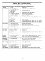
TROU
See appropriate
section in manuaJ unless directed to a Sears service centre/department.
CAUSE
PROBLEM
Does not start
Loss of power
1.
CORRECTION
Fuel shut-off valve (if so
equipped) in OFF position.
2. Safety ignition key
is not inserted.
3. Out of fuel.
4. Throttle in STOP position
(or ON/OFF switch is OFF).
5. Choke in OFF position.
6. Primer not depressed.
7. Engine is flooded.
8. Spark plug wire is
disconnected.
9. Bad spark plug.
10. Stale fuel.
11. Water in fuel.
1.
Turn fuel shut-off valve to OPEN position.
2.
insert safety ignition key.
3.
4.
Fill fuel tank with fresh, clean gasoline.
Move throttle to FAST position
(or ON/OFF switch to ON position).
Move to FULL position.
Prime as instructed in the Operation section of this manual.
Wait a few minutes before restarting, DO NOT prime.
Connect wire to spark plug.
1.
2.
3.
Spark plug wire loose.
Throwing too much snow.
Fuel tank cap is covered
with ice or snow.
Dirty or clogged muffler.
1.
2.
3.
Reconnect spark plug wire.
Reduce speed and width of swath.
Remove ice and snow on and around fuel tank cap.
4.
Clean or replace muffler.
Choke is in FULL position.
Blockage in fuel line.
Stale fuel.
Water in fuel.
Carburetor is in need of
adjustment or overhaul.
1.
2.
3.
4.
5.
Move choke to OFF position.
Clean fuel line.
Empty fuel tank & carburetor, refill with fresh, clean gasoline.
Empty fuel tank & carburetor, refill with fresh, clean gasoline.
Contact a Sears service centre/department.
Loose parts or damaged
augers or impeller.
1.
Tighten all fasteners. Replace damaged parts. If vibration
remains, contact a Sears service centre/department.
4.
Engine idles or
runs roughly
OOTING
1.
2.
3.
4.
5.
Excessive
vibration
5.
6.
7.
8.
9. Replace spark plug.
10. Empty fuel tank & carburetor, refill with fresh, clean gasoline.
11. Empty fuel tank & carburetor, refill with fresh, clean gasoline.
Recoil starter
is hard to pull
1.
Frozen recoil starter.
1.
See"lF RECOIL STARTER HAS FROZEN"
in the Operation section of this manual.
Loss of traction
drive / slowing
of drive speed
1.
2.
3.
Drive belt is worn.
Drive belt is off of pulley.
Friction drive wheel is worn.
1,
2,
3,
Check / replace drive belt,
Check / reinstall drive belt,
Contact a Sears service centre/department,
Loss of snow
discharge or
slowing of
snow discharge
1.
2.
3.
4.
Auger belt is off of pulley.
Auger belt is worn.
Clogged discharge chute.
Augers / impeller jammed.
1.
2.
3.
4.
Check / reinstall auger belt.
Check / replace auger belt.
Clean snow chute.
Remove debris or foreign object from augers / impeller.
2O
SE
CE NOTES
21
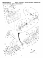
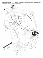
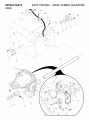
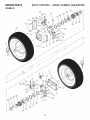
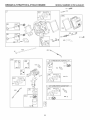
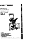
REPAIR
PARTS
AUGER
HOUSING
16
4
15
SNOW THROWER
/ iMPELLER
6/_/13
__,
- - MODEL NUMBER
944,527700
ASSEMBLY
6
12
/
10
\
14
\
5
\
7
\
47
38
\
36
/
\
\
37-
11
/
/
44
./"
/
45
/
5O
43
42
41
/
/
46
/
/
54
52
23
21
48
19
26
33
35
19
20
\
29
25
55
24
24
10
53
17
57
54
56
30
26
_ug
25
17
22
DC
3
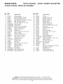
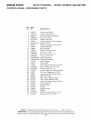
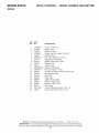
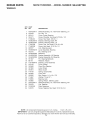
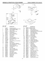
REPAIR
AUGER
PARTS
SNOW THROWER
HOUSING / IMPELLER
944,527700
ASSEMBLY
KEY PART
NO. NO.
DESCRIPTION
4
5
6
7
8
9
10
11
12
13
14
15
16
17
18
19
20
21
22
23
24
25
26
27
28
29
30
31
Pulley, Impeller
Bearing Assembly, Flange
Nut, Hex Flange 5/16-18
Bolt, Flat Head, Carriage 5/16-18x5/8
Bolt, Carriage 5/16-18
Bolt, Hex Head 5/16-18 x 5/8
Housing, Auger
Bar, Scraper
Bracket, Corner Discharge
Base, Discharge Chute
Washer, Lock 5/16
Washer, Flat
Screw, Hex Head 5/16-18 x 3/4
Fitting, Grease
Screw, Hex Head 5/16 x 1
Nut, Hex Lock 1/4-20
Nut, Hex Lock 5/16-18
Washer, Flat 5/16
Skid Plate, RH
Washer, Nylon
Wing Nut
Bolt, Carriage 5/16-18 x 3/4
Bearing, Auger
Washer, Thrust, 1"
Bolt, Shear
Skid Plate, LH
Auger Assembly, RH
Auger Assembly, LH
191079
188909
155377
180355
72250505
163183
404930X428
404933X428
178675X008
175322
10040500
19111507
74940516
405637
179582
73800400
155377
401347
178777X479
179246
128638
72270506
174658
174697
198636
174762X479
405973X498
405972X498
== MODEL NUMBER
KEY PART
NO. NO.
32
33
34
35
36
37
38
39
40
41
42
43
44
45
46
47
48
49
50
51
52
53
54
55
407768
407769
174681
174684
407757
174683
407758
407767
407760
407761
407770
407762
189282
407763
407764
407765
175321X428
74780426
407766
7836M
181160X479
72270506
198709
198638
56
57
58
180684
196710
411939
DESCRIPTION
O-Ring
Bushing, Flange 3/4
Washer, Thrust 3/4
Bearing, Thrust 3/4
Shaft, Impeller
Washer, Thrust 5/8
Bushing, Flange 5/8
Screw, Hex Head 5/16-18 x 3/4
Plug, Case
Housing, Gearbox, RH
Seal, Oil
Bushing, Flange, 1"
Key, Square 1/4 x 1/4 x 7/8
Gear, Worm
Shaft, Auger
Housing, Gearbox, LH
Impeller Assembly
Screw, Hex Head 1/4-20 x 1-5/8
Gasket, Gearbox
Pin, Roll 3/16 x 1-1/8
Bar, Drift Cutter
Bolt Carriage
Stop
Kit, Shear (Contains 6 each of Key
Numbers 19 and 28)
Multi-Wrench
Gearbox Assembly
Plug, Bearing Hole HSG
NOTE: All component dimensions given in U,S, inches,
1 inch = 25,4 mm
IMPORTANT: Use only Original Equipment Manufacturer (O,E,M,) replacement parts,
Failure to do so could be hazardous, damage your snow thrower and void your warranty,
23
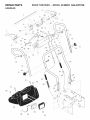
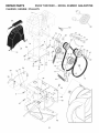
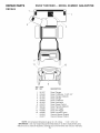
REPAIR
PARTS
CONTROL
22
/
SNOW THROWER
PANEL / DISCHARGE
- - MODEL NUMBER
944,527700
CHUTE
32
10
23
11
25
27
16\
7
18
12
14
3
8
13
15
37
31
30
8
24
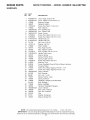
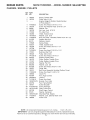
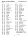
REPAIR
CONTROL
PARTS
SNOW THROWER
PANEL / DISCHARGE
== MODEL NUMBER
944,527700
CHUTE
KEY
NO.
PART
NO.
DESCRIPTION
1
2
3
4
5
6
7
8
9
10
11
12
13
14
15
16
17
18
19
20
22
23
25
26
27
28
29
30
31
32
33
34
35
36
37
414280
17501010
198475
73800600
19131316
404974
405784X479
150078
184505
179829
179246
73800400
72250505
73800500
404770X428
178633X428
179145
128415
414281
72270506
74041024
188303
155377
192001
169675
187782
187784
405400
192199
192002
192195
179246
155415
74760552
194189
Knob, Lever, Black
Screw #10-24 x 5/8
Control Assembly, Deflector
Nut, Lock 3/8-16
Washer, Flat 3/8
Control Assembly, Chute Rotater
Support, Pivot
Screw, Hex Head 5/16-18 x 3/4
Spring, Deflector
Bolt, Shoulder
Washer, Friction, Nylon
Nut, Lock 1/4-20
Bolt, Carriage 5/16-18
Nut, Lock 5/16-18
Chute Assembly
Deflector Assembly
Seal, Deflector
Rivet, Blind
Knob, Speed Control Lever, Red
Bolt, Carriage 5/16-18 x 3/4
Screw #10-24 x 1-1/2
Control Assembly, Power Steering
Nut, Hex, Flangelock 5/16-18
Lever Assembly, Speed Control
Retainer, Hairpin
Rod, Upper, Speed Control
Rod, Lower, Speed Control
Clamp, Mounting, Clean-Out Tool
Tool, Clean-Out
Bracket, Shift
Spring
Washer, Nylon
Washer
Bolt, Hex Head 5/16-18x3-1/4
Screw Hi-Lo 13-16 x 5/8
NOTE: All component dimensions given in U,S, inches,
1 inch = 25,4 mm
IMPORTANT: Use only Original Equipment Manufacturer (O,E,M,) replacement parts,
Failure to do so could be hazardous, damage your snow thrower and void your warranty,
25
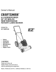
REPAIR
PARTS
SNOW THROWER
== MODEL NUMBER
944,527'700
HANDLES
4
1
5
\\
\,
15
/
11
-19
5
17
!
/
/
/
10
/"
22
i
11
22
15
/
/
12
\
14
16
47
17-
31 _
...... 32
\
32
\
\
3O
29
4O
26
_-23
REPAIR
PARTS
SNOW THROWER
- - MODEL NUMBER
944,527700
HANDLES
KEY
NO.
PART
NO.
DESCRiPTiON
1
2
4
5
6
7
8
9
10
11
12
13
14
15
16
17
18
19
22
23
24
25
26
27
28
29
30
31
32
33
34
35
36
37
38
-39
40
42
43
44
45
46
47
405999X479
405783X479
178888
169675
17060408
178652
196333X008
196334X008
196619X479
74780524
74780528
414519X479
414518X479
751153
19131316
178899
193447
180485
72120618
178643X479
180447
180926
178669
17000616
412680
408059
182906
175262
184471
196335X008
401369
68038
178831
193885
178666
401620
178668
180964
196336X008
199638
196338
700279
57079
192091
Lever, Auger Control, RH
Lever, Traction Drive Control, LH
Bushing, Flange
Retainer, Hairpin
Screw, Hex Head 1/4-20 x 3/4
Rod, Interlock
Arm, Impeller Rod
Arm, Traction Rod
Panel, Control
Screw, Hex Head 5/16-18 x 1-1/2
Screw, Hex Head 5/16-18 x 1-3/4
Handle Tube, LH
Handle Tube, RH
Nut, Lock 5/16-18
Washer, Flat 3/8
Knob, Handle
Rod, Auger Control
Rod, Traction Control
Bolt, Carriage 3/8-16 x 2-1/4
Handle Tube, Lower
Sleeve, Spring
Spring, Traction Drive
Spring, Auger Control
Screw, Hex Head 3/8-16 x 1
Bushing, Pivot
Screw, Headlight Ground Wire to Blower Housing
Console, Panel
Screw, Hex Head, Tapping #10-24 x 1-1/4
Screw, Hex Head, Tapping #10-24 x 1/2
Latch, Interlock
Bolt, Shoulder
Nut, Lock 1/4-20
Spring, Torsion, Lever
Spring, Interlock
Headlight, Halogen (Includes Bulb)
Bulb, Halogen
Bezel, Headlight
Harness, Headlight (Halogen)
Lever, Interlock
Rod, Latch, Interlock
Rod, Arm, Interlock
Clip
Washer, Hardened
Sleeve, Spring Trac
NOTE: All component dimensions given in U,S, inches,
1 inch = 25,4 mm
iMPORTANT: Use only Original Equipment Manufacturer (O,E,M,) replacement parts,
Failure to do so could be hazardous, damage your snow thrower and void your warranty,
27
REPAIR
PARTS
SNOW THROWER
- - MODEL NUMBER
944,527700
DRIVE
13
1
5
3
16
14
11
7
/
4
12
28
I0
13
REPAIR
PARTS
SNOW THROWER
- - MODEL NUMBER
944,527700
DRIVE
KEY
NO.
PART
NO.
DESCRiPTiON
1
2
3
4
5
6
7
8
9
10
11
12
13
14
15
16
18
19
20
21
22
23
17490508
187794
174697
74780632
179830
73930600
187776
187787
700279
188101
193255X479
73800400
150078
193256
191995
404308
198466
192000
191993
87930
17391208
146315
Screw 1/4-20 x 1/2
Spacer, Axle
Washer, Thrust
Screw, Cap, Hex Head 3/8-16 x 2
Bearing, Axle
Nut, Hex, Centerlock 3/8-16
Transmission Assembly
Speed Control Arm, Hydro
Retainer Clip
Torque Strap
Bracket, Anti-Rotate
Nut, Hex, Nylock 1/4-20
Screw, Hex Washer Head 5/16-18 x 3/4
Rod, Bypass Valve
Pop Rivet
Shaft, Axle
Cable, Drive Control
Bracket, Cable, Rear
Bracket, Cable, Front
Clip, Cable
Screw, Slotted Hex Head 1/8 x 1/2
Screw, Hex Head 5/16-18 x 3/4
NOTE: All component dimensions given in U,S, inches,
1 inch = 25,4 mm
IMPORTANT: Use only Original Equipment Manufacturer (O,E,M,) replacement parts,
Failure to do so could be hazardous, damage your snow thrower and void your warranty,
29
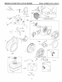
REPAIR
SNOW THROWER
PARTS
- - MODEL NUMBER
944,527700
58
19
24
56
29
26
_31
34
27
51
5O
52
35
15
44
/
/
11
46
3O
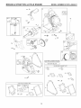
REPAIR
CHASSIS
PARTS
SNOW THROWER
== MODEL NUMBER
944,527700
/ ENGINE / PULLEYS
KEY
NO.
1
2
3
4
5
6
7
8
9
10
11
12
13
14
15
16
17
18
19
20
21
22
23
24
25
26
27
28
29
31
34
35
42
44
45
46
47
49
50
51
52
56
57
58
PART
NO.
192873
180522
-
-
-
74780520
150078
59289
166785
175330
192383
10040500
17490508
410420
85179
178828
408007
150406
187786
74780524
175331
180523
74610516
409475
180478
179157
400026
850263
851084
193607
192213
17490408
198580
405484
73930500
71210616
193397X479
403732
184471
415004X428
192115X428
406109
57079
183537X428
11050500
198563
DESCRIPTION
Spring, Traction idler
Pulley, idler (2-1/4)
Engine, Briggs & Stratton, Model Number
21 P214-O942-E1
Screw, Hex Head 5/16-18 x 1-1/4
Screw, Hex Washer Head 5/16-18 x 3/4
Washer, Flat
Nut, Jam, Lock 5/16-18
Pin, idler Pivot
V-Belt, Traction Drive
Washer, Lock 5/16
Bolt, Hex Head, Threaded, Rolled 5/16-18 x 1/2
impeller Idler Arm
Retainer, Hairpin
Spring, Brake
V-Belt, Impeller Drive
Screw, Hex Head 3/8-16 x 1-1/4
Arm, Idler
Screw, Hex Head 5/16-18 x 1-1/2
Bushing, Idler Pivot
Pulley, Idler (2-3/4)
Screw, Hex Head 5/16-18 x 1
Spacer, Engine Pulley
Pulley, Engine, Traction Drive
Pulley, Engine, Impeller Drive
Washer, Flat 3/8
Washer, Lock 3/8
Screw, Hex Head 3/8-24 x 1-3/8
Guide, Belt
Belt Cover Assembly (includes Toolbox Cover)
Screw, Hex Head 1/4-20 x 1/2
Clevis Pin
Arm, Auger Control
Locknut
Screw, Hex Head
Bracket, Pivot, Idler
Pan, Frame Bottom
Screw Shoulder
Frame Assembly
Plate, Frame End
Shaft, Auger Control
Washer, Hardened
Mounting Plate, Engine
Washer, Lock, External Tooth 5/16
Power Cord
NOTE: All component dimensions given in U,S, inches,
1 inch = 25,4 mm
iMPORTANT: Use only Original Equipment Manufacturer (O,E,M,) replacement parts,
Failure to do so could be hazardous, damage your snow thrower and void your warranty,
31
REPAIR
PARTS
SNOW THROWER
- - MODEL NUMBER
944,527700
WHEELS
24
14
23
21
3',
28
25
31
22
2
S
13
2
10
15
13
12
16
10
19
11
25
"20
5
6
22
21
33
23
24
32
3
REPAIR
PARTS
SNOW THROWER
- - MODEL NUMBER
944,527700
WHEELS
KEY
NO.
PART
NO.
1
2
3
4
7
8
9
10
11
12
13
14
15
16
17
18
19
20
21
22
23
24
25
26
27
28
29
30
31
32
33
34
196752X417
155443
405161
184471
17060410
185603X479
185602X004
17600406
17490508
405077
193506X479
182015
194944X008
194939X008
194943X008
181847
85179
179148X479
192126
182466
187622
194941
179139
194940
189282
174697
179830
193885
196753X417
700279
12000045
146315
DESCRIPTION
Wheel Assembly, 16", with Power Steering, LH
Pin, Klik 1/4
Cover, Power Steering
Screw, Shoulder, Hex Head #10-24 x 1/2
Screw, Hex Head 3/8-16 x 1
Bracket, Steering Cable, RH
Bracket, Steering Cable, LH
Screw, Cap, Hex Head 5/16-18 x 3/4
Screw, Hex Head 5/16-18 x 1/2
Link, Steering Lever
Lever Assembly, Steering
Pin, Steering Lever
Bellcrank
Bracket Assembly, LH Steering
Bracket Assembly, RH Steering
Pin, Steering Bellcrank
Retainer, Hairpin
Bracket, Lever Assembly
Driver, Wheel
Ring, Wire Retainer
Lobe, Wheel
Slide, Clutch
Spring, Clutch Slide
Lobe, Axle
Key, Square 1/4 x 1/4 x 7/8
Washer, Thrust (1 ")
Bearing, Axle
Spring, Return, Steering Latch
Wheel Assembly, 16", with Power Steering, RH
Clip, Retainer
Ring, Retaining
Screw, Tapping, Hex Head 5/16-18 x 3/4
NOTE: All component dimensions given in U,S, inches,
1 inch = 25,4 mm
IMPORTANT: Use only Original Equipment Manufacturer (O,E,M,) replacement parts,
Failure to do so could be hazardous, damage your snow thrower and void your warranty,
33
REPAIR
SNOW THROWER
PARTS
- - MODEL NUMBER
944,527700
DECALS
1
4
11
6
KEY
NO.
1
2
3
4
5
6
9
10
11
12
13
---
PART
NO.
DESCRIPTION
181037
415449
181035
181042
183876
181033
415475
183730
415399
415398
415455
414916
414917
Decal Danger
Decal Craftsman, 13 HP/30"
Decal Danger, Deflector
Decal Danger
Decal Craftsman
Decal Instruction
Decal Speed Control
Decal Remote Deflector
Decal LH Trigger
Decal RH Trigger
Decal Console, Hydro
Owner's Manual, English
Owner's Manual, French
NOTE: All component dimensions given in U.S. inches.
1 inch = 25.4 mm
IMPORTANT." Use only Original Equipment Manufacturer (O.E.M.) replacement parts.
Failure to do so could be hazardous, damage your snow thrower and void your warranty.
34
BRIGGS & STRATTON
4-CYCLE
ENGINE
MODEL NUMBER 21P214=0942=E1
11
307
3O61
8 /
',-q_842
1351
287
J
24
741
X
552_718
524
718A
_
529
725
746
1298
742 _
@
_}_
12
_329 REPLACEMENT
ENGINE_
48 SHORT BLOCK
I
358 ENGINE GASKET SET
3
2O
51A
22
163
1095 VALVE GASKET SET
51A_
12
1022
363(_
ss3(_
35
%
BRIGGS & STRATTON
4-CYCLE
ENGINE
MODEL NUMBER 21P214o0942-E1
1171
l
t_
_
_7_
383_
45 _
121 CARBURETOR
108
OVERHAUL
KIT
127 ©
137
lO4 _
163 %
105 [_
117
51A(
633
@
51Aq
135
117
369
977 CARBURETOR
GASKET
51A(
163
SET
105 [_
%
_J
633 @
137
137
1127 ?
36
(_
o_4_
BRIGGS & STRATTON
4-CYCLE
ENGINE
MODEL NUMBER 21P214o0942-E1
613
732
472
1251A
610
1288
990
I
1036 EMISSIONS
LABEL
I
1011
53
597
_@
456
1251
528
684950
_
1252 _)
1211
3O4
654;_
697,_
731
309
930
8o_
100_
967_
8_6
1070
455
1119
332
334
601
190'_
37
BRIGGS & STRATTON
4-CYCLE
ENGINE
MODEL NUMBER 21P214-0942-E1
663_
163%
1227I
.....
281
I
278
505 @
618
1230_}
209 j
188
1138
616_
211S
773
271 _
668A @
188
564
604
821
KEY
NO.
1
2
3
5
7
11
12
13
15
15A
16
18
19
20
21
22
23
24
25
26
27
28
29
3O
32
33
34
35
36
42
45
46
48
PART
NO.
794850
698340
391086s
794871
697690
696750
694953
794829
695757
691686
794720
791965
698340
391086s
281658s
794825
794812
222698s
791819
79181 8
697692
697698
690975
696581
694691
694692
690976
499596
792200
694865
694865
499586
690977
790958
79491 5
•
"+
•
•
DESCRIPTION
KEY PART
NO. NO.
Cylinder Assembly
Kit-Bushing/Seal (Magneto Side)
Seal-Oil (Magneto Side)
Head-Cylinder
Gasket-Cylinder Head
Tube-Breather
Gasket-Crankcase
Screw (Cylinder Head)
Plug-Oil Drain
Plug-Oil Drain
Crankshaft
Cover-Crankcase
Kit-Bushing/Seal (PTO Side)
Seal-Oil (PTO Side)
Cap-Oil Fill
Screw (Crankcase Cover/Sump)
Flywheel
Key-Flywheel
Piston Assembly (Standard)
Piston Assembly (.020" Oversize)
Ring Set (Standard)
Ring Set (,020" Oversize)
Lock-Piston Pin
Pin-Piston
Rod-Connecting
Dipper-Connecting Rod
Screw (Connecting Rod)
Valve-Exhaust
Valve-Intake
Spring-Valve (Intake)
Spring-Valve (Exhaust)
Keeper-Valve
Tappet-Valve
Camshaft
Short Block
51
51A
53
55
58
60
65
95
97
98
104
105
108
109
117
118
121
122
125
127
130
133
135
137
146
163
187
188
190
192
209
211
219
220
222
227
38
694874.+
694875,+
795017
696710
693389
695740
699851
690718
696387
695408
694918
696136
696736
793162
696134
696135
696146
694876
793161
690727
696139
694914
696142
695426
690979
692277
698080
699479
699220
690083
694867
695307
693578
691724
794800
694864
DESCRIPTmON
(_:Gasket-lntake
O$Gasket-lntake
o
o
4-
Stud (Carburetor)
Housing-Rewind Starter
Rope-Starter (Cutto Required Length)
Grip-Starter Rope
Screw (Starter Motor)
Screw (Throttle Valve)
Shaft-Throttle
Kit-Idle Speed
Pin-Float Hinge
Valve-Float Needle
Valve-Choke
Shaft-Choke
Jet-Main (Standard)
Jet-Main (High Altitude)
Kit-Carburetor Overhaul
Spacer-Carburetor
Carburetor
Plug-Welch
Valve-Throttle
Float-Carburetor
Tube-Fuel Transfer
$ Gasket-Float Bowl
Key-Timing
(_ Gasket-Air Cleaner
Line-Fuel
Screw (Control Bracket)
Screw (Fuel Tank)
Adjuster-Rocker Arm
Spring-Governor
Spring-Governed Idle
Gear-Governor
Washer (Governor Gear)
Bracket-Control
Lever-Governor Control
BRIGGS & STRATTON
KEY
NO.
271
278
281
287
300
304
305
306
307
309
332
333
334
337
356
358
369
383
410
427
455
456
459
472
474
485
504
505
523
524
525
528
529
552
562
564
597
601
604
604A
608
610
613
613A
615
616
621
632
633
635
663
668
668A
676
677
689
697
718
718A
725
PART
NO.
4-CYCLE
ENGINE
MODEL NUMBER 21P214=0942=E1
KEY
NO.
DESCRIPTION
698035
Lever-Control
792008
Washer (Governor Control Lever)
697268
Panel-Control
699629
Screw (Dipstick Tube)
794948
Muffler
791478
Housing-Blower
699480
Screw (Blower Housing)
697240
Shield-Cylinder
794822
Screw (Cylinder Shield)
793524
Motor-Starter
794824
Nut (Flywheel)
492341
Armature-Magneto
699477
Screw (Magneto Armature)
691043
Plug-Spark
793206
Wire-Stop
697715
Gasket Set-Engine
695422
Spring-Float Bowl
19374s
Wrench-Spark Plug
695382
Link-Control
694255
Nut (Control Bracket)
795011
Cup-Flywheel
692299
Plate-Pawl Friction
281505s
PawI-Ratchet
791948
Knob-Choke Shaft
793640
Alternator
695755
Knob-Control
694254
Washer Set-Friction
691251
Nut (Governor Control Lever)
695344
Dipstick
691876
SeaI-O Ring (Dipstick Tube)
795343
Tube-Dipstick
793006
Hose-Primer
791822
Grommet
694674
Bushing-Governor Crank
793216
Bolt (Governor Control Lever)
699854
Screw (Control Cover)
691696
Screw (Pawl Friction Plate)
791850
Clamp-Hose
696758
Cover-Control
790473
Cover-Control
699335
Starter-Rewind
794541
Attester-intake
794846
Screw (Muffler)
794844
Screw (Muffler)
694676
Retainer-Governor Shaft
694675
Crank-Governor
692310
Switch-Stop
695917
Spring/Link-Mechanical Governor
690998 O$ Seal-Choke/Throttle Shaft
691909
Boot-Spark Plug
699854
Screw (Control Panel)
794539
Spacer
694257
Spacer
697816
Deflector-Muffler
699776
Screw (Muffler Deflector)
691855
Spring-Friction
795012
Screw (Starter Motor)
690959
Pin-Locating
695178
Pin-Locating
696756
Shield-Heat
727
731
731A
732
741
742
746
773
798
832
836
842
847
851
868
883
892
914
930
957
972
975
977
990
998
1005
1011
1022
1023
1026
1029
1036
PART
NO.
DESCRIPTION
Cover-Starter Drive
Hood-Snow
Hood-Snow
Screw (Starter Drive Cover)
Gear-Timing
Retainer-E Ring
Gearqdler
Retainer-E Ring
Screw (Rocker Cover)
Guard-Muffler
Screw (Muffler Guard)
SeaI-O Ring (Dipstick Tube)
Dipstick/Tube Assembly
Terminal-Spark Plug
Seal-Valve
=+
Gasket-Exhaust
=+
Switch-Key
Screw (Rocker Cover)
Guard-Rewind
Cap-Fuel
Tank-Fuel
Bowl-Float
Gasket Set-Carburetor
Key Set
Pipe-Oil
Fan-Flywheel
Tube-Vent
Gasket-Rocker Cover
=+
Cover-Rocker
Rod-Push
Arm-Rocker
Label-Emissions (Available from an
authorized Briggs & Stratton Service
Dealer)
1070
794821
Screw (Flywheel Fan)
Gasket Set-Valve
1095
695440
Pivot-Rocker Arm
1100
791959
1119
699772
Screw (Alternator)
1127
695407
Screw (Float Bowl)
1171
794828
Stud (Rocker Arm Cover)
1196
696692
Screw (Snow Hood)
1210
498144
Pulley/Spring Assembly (Pulley)
1211
498144
Pulley/Spring Assembly (Spring)
1230
699847
Stud (Control Bracket)
1251
696762
Shield-Snow
1251A 790471
Shield-Snow
1252
699480
Screw (Snow Shield)
1288
794838
Nut (Snow Hood)
1298
795016
Nut (Heat Shield)
Knob-Snow Hood
1318
698111
1329
21P214-0017 Replacement Engine
1351
794847
Stud (Cylinder Shield)
(_
+
697465
793174
794550
699200
691288
692564
694679
694258
697890
699223
699234
795015
790476
692424
794086
695398
791944
794827
696709
698109
694260
696138
696147
695756
792928
794815
794544
690971
698042
695177
690972
Included
Included
Included
Included
in
in
in
in
Engine Gasket Set, Key. No. 358
Carburetor Overhaul Kit, Key. No. 121
Carburetor Gasket Set, Key. No. 977
Valve Gasket Set, Key. No, 1095
NOTE: All component dimensions given in U,S, inches
1 inch = 25,4 mm
39
Just Call:
1-800-4-1VlY-HOIVlE®
(1-800-469-4663)
24 hours a day, 7 days a week
For the repair of major brand appliances in your own home...
no matter who made it, no matter who sold it!
For your nearest Sears Parts and Service location,
to bring in products like vacuums, lawn equipment and electronics.
For Sears Parts & Service, to order the replacement parts,
accessories and owner's manuals that you need to do-it-yourself.
WWW,Sears,ca
iiiiiiiiiiiiiiiiiii
iiiiiiiiiiiiiiiiiii
iiiiiiiiiiiiiiiiiii
iiiiiiiiiiiiiiiiiii
iiiiiiiiiiiiiiiiiii
iiiiiiiiiiiiiiiiiii
iiiiiiiiiiiiiiiiiii
iiiiiiiiiiiiiiiiiii
iiiiiiiiiiiiiiiiiii
iiiiiiiiiiiiiiiiiii
iiiiiiiiiiiiiiiiiii
iiiiiiiiiiiiiiiiiii
iiiiiiiiiiiiiiiiiii
iiiiiiiiiiiiiiiiiii
iiiiiiiiiiiiiiiiiii
iiiiiiiiiiiiiiiiiii
iiiiiiiiiiiiiiiiiii
iiiiiiiiiiiiiiiiiii
iiiiiiiiiiiiiiiiiii
iiiiiiiiiiiiiiiiiii
iiiiiiiiiiiiiiiiiii
iiiiiiiiiiiiiiiiiii
iiiiiiiiiiiiiiiiiii
iiiiiiiiiiiiiiiiiii
iiiiiiiiiiiiiiiiiii
iiiiiiiiiiiiiiiiiii
iiiiiiiiiiiiiiiiiii
iiiiiiiiiiiiiiiiiii
iiiiiiiiiiiiiiiiiii
HHHHHHHHH_
(_) / TM
Trademarks of Sears, Roebuck and Co. used under license by Sears Canada
M_Marque d_pos_e / MCMarque de commerce de Sears, Roebuck and Co. utilisee en vertu d'une licence de Sears Canada
414916 08.14.07 AP
Printed in the U.S.A.