1
OC287-1.qxp
03.3.19 10:46 AM
Page 1
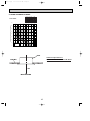
SPLIT-TYPE, HEAT PUMP AIR CONDITIONERS
SPLIT-TYPE, AIR CONDITIONERS
2003
No.OC287
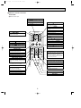
TECHNICAL & SERVICE MANUAL
Series PLA
Ceiling Cassettes R407C
Indoor unit
[Model names]
[Service Ref.]
PLA-P3AA
PLA-P3AA
• Refer to the OCT03 REVISED
EDITION-E as for control relation.
• This manual does not cover
outdoor units. When serving
them, please refer to the service
manual No.OC285, OC261
REVISED EDITION-B and this
manual in a set.
CONTENTS
INDOOR UNIT
CHECK TEST RUN
MODEL SELECT
˚C
AMPM
AMPM
NOT AVAILABLE
ON/OFF
CENTRALLY CONTROLLED
ON
TEMP
1Hr.
OFF
˚C
CLOCK
CHECK
˚C
STAND BY
DEFROST
ERROR CODE
TEMP.
WIRELESS REMOTE
CONTROLLER
NOT AVAILABLE
FILTER
CHECK MODE
TEST RUN
FUNCTION
ON/OFF
WIRED REMOTE
CONTROLLER
1. COMBINATION OF INDOOR AND OUTDOOR UNITS ··2
2. SAFETY PRECAUTION ·······························2
3. PART NAMES AND FUNCTIONS ···············4
4. SPECIFICATIONS ········································7
5. DATA ····························································9
6. OUTLINES AND DIMENSIONS ·················17
7. WIRING DIAGRAM ·······································18
8. REFRIGERANT SYSTEM DIAGRAM··············19
9. TROUBLESHOOTING ·······························20
10. DISASSEMBLY PROCEDURE ··················22
11. PARTS LIST ···············································25
12. OPTIONAL PARTS ····································28
OC287-1.qxp
1
03.3.19 10:46 AM
Page 2
COMBINATION OF INDOOR AND OUTDOOR UNITS
Indoor unit
Outdoor unit(OC285)
Outdoor unit(OC261 REVISED EDITION-B)
Heat pump type Cooling only type Heat pump type Cooling only type
PUH-P3
PUH-P3
PU-P3
PU-P3
VGAA
VGAA
VGAA.UK YGAA.UK VGAA.UK YGAA.UK
VGAA1.UK YGAA1.UK VGAA1.UK YGAA1.UK
PLA-P3AA
2
SAFETY PRECAUTION
Cautions for devices that use R407C refrigerant.
· Do not use the existing refrigerant piping.
-The old refrigerant and lubricating oil in the existing piping contains a large amount of chlorine which may cause the lubricating
oil of the new unit to deteriorate.
· Use “low residual oil piping”.
-If there is a large amount of residual oil (hydraulic oil, etc.) inside the piping and joints, deterioration of the lubricating oil will
result.
· Store the piping to be used during installation indoors and keep both ends of the piping sealed until just before
brazing. (Store elbows and other joints in a plastic bag.)
-If dust, dirt, or water enters the refrigerant cycle, deterioration of the oil and compressor trouble may result.
· Use Suniso 4GS or 3GS (small amount) as the lubricating oil to coat flares and flange connection parts.
-The lubricating oil used with the air conditioner is highly hygroscopic. If it is used, water may be mixed in and deterioration
of the lubricating oil may result.
· Use liquid refrigerant to charge the system.
-If gas refrigerant is used to charge the system, the composition of the refrigerant in the cylinder will change and performance may drop.
· Do not use a refrigerant other than R407C.
-If another refrigerant (R22, etc.) is used, the chlorine in the refrigerant may cause the lubricating oil to deteriorate.
· Use a vacuum pump with a reverse flow check valve.
-The vacuum pump oil may flow back into the refrigerant cycle and cause the lubricating oil to deteriorate.
2
OC287-1.qxp
03.3.19 10:46 AM
Page 3
[1] Service tools
Use the below service tools as exclusive tools for R407C refrigerant.
No. Tool name
1 Gauge manifold
2 Charge hose
3
4
5
6
7
Electronic scale
Gas leak detector
Adapter for reverse flow check.
Refrigerant charge base.
Refrigerant cylinder.
Specifications
·Only for R407C.
·Use the existing fitting SPECIFICATIONS. (UNF7/16)
·Use high-tension side pressure of 3.4 MPa or over.
·Only for R407C.
·Use pressure performance of 5.1 MPa or over.
·Use the detector for R134a or R407C.
·Attach on vacuum pump.
·For R407C ·Top of cylinder (Brown)
·Cylinder with syphon
8 Refrigerant recovery equipment.
[2] Notice on repair service
·After recovering all the refrigerant in the unit, work may be started.
·Do not release the refrigerant in the air.
·After completing the repair service, recharge the system with the specified amount of the
liquid refrigerant.
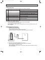
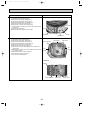
[3] Refrigerant recharging
(1) Refrigerant recharging process
Direct charging from the cylinder.
·Confirm that the cylinder is suitable for syphoning.
·Raise the cylinder and recharge the unit by syphoning liquid refrigerant.
Unit
Gravimeter
(2) Recharge when refrigerant leakage has occurred.
·After recovering all the refrigerant in the unit, work may be started.
·Do not release the refrigerant in the air.
·After completing the repair service, recharge the system with the specified amount of
the liquid refrigerant.
3
OC287-1.qxp
3
03.3.19 10:46 AM
Page 4
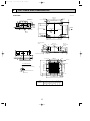
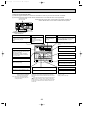
PART NAMES AND FUNCTIONS
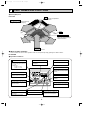
● Indoor (Main) Unit
PLA-P3AA
Filter
Removes dust and pollutants
from intake air
Horizontal Air Outlet
Sets airflow of horizontal automatically
during cooling or dehumidifying.
Grille
Auto Air Swing Vane
Disperses airflow up and
down and adjusts the angle
of airflow direction.
Air Intake
Intakes air from room.
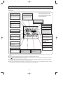
● Wired remote controller
On the controls are set, the same operation mode can be repeated by simply pressing the ON/OFF button.
PLA-P3AA
● Operation buttons
TEMP. ADJUSTMENT button
This sets the room temperature. The
temperature setting can be performed
in 1: units
Setting range
Cooler 19: to 30:
Heater 17: to 28:
TIME SETTING button
AIR SPEED button
This sets the current time, start time
and stop time.
This sets the ventilation fan speed.
ON/OFF button
This switches between the operation
and stop modes each time it is pressed.
The lamp on this button lights during
operation.
TIMER button
1Hr.
CENTRALLY CONTROLLED
ON
This switches between continuous
operation and the timer operation.
OFF
˚C
CLOCK
CHECK
˚C
STAND BY
DEFROST
ERROR CODE
NOT AVAILABLE
TEMP.
FILTER
CHECK MODE
TEST RUN
FUNCTION
ON/OFF
AIR DIRECTION button
This adjusts the vertical angle of the
ventilation.
FILTER
OPERATION SWITCH button
Press this button to switch the cooler,
electronic dry (dehumidify), automatic
and heater modes.
CHECK TEST
PAR-20MAA
FILTER button
TIMER SET
This resets the filter service indication
display
LOUVER button
VENTILATION button
CHECK-TEST RUN button
This switch the horizontal fan motion
ON and OFF.
This sets the ventilation fan speed.
Only press this button to perform an
inspection check or test operation.
Do not use it for normal operation.
(Not available for this model.)
4
OC287-1.qxp
03.3.19 10:46 AM
Page 5
● Display
CENTRALLY
CONTROLLED display
This indicates when the unit is controlled by optional features such as
central control type remote controller.
In this display example on the bottom left, a condition where all display lamps light is shown for explanation purposes although this differs
from actual operation.
CLOCK display
The current time , start time and stop
time can be displayed in ten second
intervals by pressing the time switch
button. The start time or stop time is
always displayed during the timer
operation.
AIR DIRECTION display
TIMER display
This displays the air direction.
This indicates when the continuous
operation and time operation modes
are set.
It also display the time for the timer
operation at the same time as when
it is set.
AIR SPEED display
The selected fan speed is displayed.
ROOM TEMPERATURE
1Hr.
CENTRALLY CONTROLLED
OPERATION MODE display
This indicates the operation mode.
ON
OFF
˚C
CLOCK
CHECK
˚C
STAND BY
DEFROST
ERROR CODE
TEMP.
NOT AVAILABLE
FILTER
CHECK MODE
TEST RUN
FUNCTION
ON/OFF
display
The temperature of the suction air
is displayed during operation. The
display range is 8°C to 39°C. The
display flashes 8°C when the actual
temperature is less than 8°C and
flashes 39°C when the actual temperature is greater than 39°C.
FILTER
STANDBY display
The [STANDBY] symbol is only displayed from the time the heating
operation starts unit the heated air
begins to blow.
CHECK TEST
PAR-20MAA
TIMER SET
Operation lamp
This lamp lights during operation,
goes off when the unit stops and
flashes when a malfunction occurs.
CHECK MODE
TEST RUN
DEFROST display
display
This display lights in the check mode
or when a test operation is performed.
This indicates when the defrost operation is performed.
FILTER display
This lamp lights when the filter need
to be cleaned.
CHECK display
This indicates when a malfunction
has occurred in the unit which should
be checked.
SET TEMPERATURE display
POWER display
This displays the selected setting
temperature.
This lamp lights when electricity is
supplied to the unit.
Caution
● Only the Power display lights when the unit is stopped and power supplied to the unit.
● When the central control remote control unit, which is sold separately, is used the ON-OFF button, operation switch button
and
TEMP. adjustment button do not operate.
● “NOT AVAILABLE” is displayed when the Air speed button are pressed.This indicates that this room unit is not equipped
with the fan direction adjustment function and the louver function.
● When power is turned ON for the first time, it is normal that “H0” is displayed on the room temperature indication (For max.
2minutes). Please wait until this “H0” indication disappear then start the operation.
5
OC287-1.qxp
03.3.19 10:46 AM
Page 6
● Wireless remote controller
PLA-P3AA
● When cover is open.
CHECK TEST RUN display
CHECK&TEST RUN display indicates that
the unit is being checked or test-run.
MODEL SELECT display
display
Blinks when model is selected.
Lights up while transmission to the indoor
unit is mode using switches.
display
SET TEMP. display indicates desired temperature set.
CLOCK display
display
Displays the current time.
OPERATION MODE display
Operation mode display indicates which operation mode is in effect.
TIMER display
CHECK TEST RUN
MODEL SELECT
˚C
AMPM
Displays when in timer operation or when
setting timer.
“
AMPM
NOT AVAILABLE
display
The vertical direction of air flow is indicated.
ON/OFF
” display
Displays the order of timer operation.
“
TEMP
”“
”“
” display
Displays whether timer is on or off.
display
button
FAN SPEED display indicates which fan
speed has been selected.
FAN
AUTO STOP
VANE
AUTO START
SET TEMPERATURE button sets any desired
room temperature.
ON/OFF button
The unit is turned ON and OFF alternately
each time the button is pressed.
MODE
CHECK LOUVER
h
FAN SPEED SELECT button
Used to change the fan speed.
MODE SELECT button
TEST RUN
SET
min
RESET
TIMER CONTROL buttons
AUTO STOP (OFF timer): when this switch
is set, the air conditioner will be automatically stopped at the preset time.
AUTO START (ON timer): when this switch
is set, the air conditioner will be automatically started at the preset time.
CLOCK
Used to switch the operation mode between
cooling, drying, blowing, heating and auto
mode.
h and min buttons
Buttons used to set the “hour and minute” of
the current time and timer settings.
w In case the outdoor unit is cool only type,
the heating mode is not available.
LOUVER button
CHECK-TEST RUN button
This switch the horizontal fan motion ON
and OFF.
Only press this button to perform an inspection check or test operation.
Do not use it for normal operation.
(Not available for this model.)
CLOCK button
VANE CONTROL button
RESET button
Used to change the air flow direction.
SET button
6
03.3.19 10:46 AM
4
Page 7
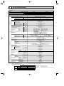
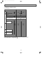
SPECIFICATIONS
1. Heat pump type
Service Ref.
Item
Function
PLA-P3AA
Total input
Indoor unit
Service Ref.
PLA-P3AA
Power supply (phase, cycle,voltage)
Input
Running current
Starting current
External finish (Panel)
Heat exchanger
Fan (drive) o No.
Fan motor output
Fan
Airflow (Lo-Mi2-Mi1-Hi)
External static pressure
Booster heater
Operation control & Thermostat
Sound level (Lo-Mi2-Mi1-Hi)
Unit drain pipe I.D.
W
Dimensions
D
H
Weight
Single phase, 50Hz, 220-230-240V
kW
A
A
kW
K/ min (CFM)
Pa (mmAq)
kW
dB
mm (in.)
mm (in.)
mm (in.)
mm (in.)
kg (lbs.)
Service Ref.
Power supply (phase, cycle, voltage)
Running current
A
Starting current
A
Outdoor unit
External finish
NOTE:
Refrigerant control
Compressor
Model
Motor output
Starter type
Protection devices
kW
W
Crankcase heater
Heat exchanger
Fan (drive) o No
kW
Fan
Fan motor output
K/ min (CFM)
Airflow
Defrost method
dB
Cooling
Sound level
dB
Heating
mm (in.)
W
mm (in.)
Dimensions
D
mm (in.)
H
kg (lbs.)
Weight
Refrigerant
kg (lbs.)
Charge
L
Oil (Model)
mm (in.)
Liquid
Pipe size O.D.
mm (in.)
Gas
Indoor side
Connection method
Outdoor side
Between the indoor & Height difference
outdoor units
Piping length
1. Rating conditions (ISO T1)
Cooling Indoor : D.B. 27°C (80°F) W.B. 19°C (66°F)
Heating Indoor : D.B. 20°C (80°F)
Refrigerant piping length (one way) : 5m (16ft.)
2. Guaranteed operating range
Indoor
Upper limit
Lower limit
Upper limit
Heating
Lower limit
Cooling
Heating
31,700
9,300
3.50
Cooling
26,600
7,800
3.44
Btu/h
W
kW
Capacity
Refrigerant piping
OC287-1.qxp
D.B. 35˚C, W.B. 22.5˚C
D.B. 19˚C, W.B. 15˚C
D.B. 28˚C
D.B. 17˚C
0.17
0.81
1.0
0.17
0.81
1.0
Munsell 0.70Y 8.59/0.97
Plate fin coil
Turbo fan (direct) o 1
0.070
15-16-18-20 (530-565-635-705)
0 (direct blow)
—
Remote controller & built-in
28-30-32-34
32 (1-1/4)
UNIT : 840 (33-1/16) PANEL : 950 (37-3/8)
UNIT : 840 (33-1/16) PANEL : 950 (37-3/8)
UNIT : 258 (10-1/2)
PANEL : 30 (1-3/16)
UNIT : 24 (53)
PANEL : 5 (11)
PUH-P3VGAA
PUH-P3VGAA.UK
PUH-P3YGAA.UK
PUH-P3VGAA1.UK PUH-P3YGAA1.UK
Single phase, 50Hz, 220-230-240V / 3 phase, 50Hz, 380-400-415V (4wires)
15.98············GAA
15.01············GAA
15.76/5.63····GAA(1).UK
14.81/5.29····GAA(1).UK
93/47
Munsell 5Y 8/1······GAA
Munsell 5Y 7/1······GAA(1).UK
Linear expansion valve
Hermetic
NE52VNJMT/NE52YDKMT
2.5
Line start
Inner thermostat,
Thermal relay,
HP switch, Discharge thermo HP switch, Discharge thermo.
38
Plate fin coil
Propeller (direct) o 1
0.070
50 (1,770)
Reverse cycle
49
51
900(35-7/16)
330+20(13+3/4)
855(33-5/8)
79(174)
R407C
3.3(7.3)
1.3 (Ester) MEL56
9.52(3/8)
15.88(5/8)
Flared
Flared
Max. 50m
Max. 50m
Outdoor : D.B. 35°C (95°F) W.B. 24°C (75°F)
Outdoor : D.B. 7°C (45°F) W.B. 6°C (43°F)
Outdoor
D.B. 46˚C
D.B. -5˚C
D.B. 24˚C, W.B. 18˚C
D.B. -11˚C, W.B. -12˚C
7
3. Above data based on indicated voltage
Indoor unit
Single phase 240V 50Hz
Outdoor unit
Single phase 240V 50Hz / 3 phase 415V 50Hz
OC287-1.qxp
03.3.19 10:46 AM
Page 8
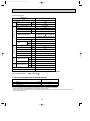
2. Cooling only type
Service Ref.
Item
Function
PLA-P3AA
Cooling
26,600
7,800
3.44
Btu/h
W
kW
Capacity
Total input
Indoor unit
Service Ref.
PLA-P3AA
Power supply (phase, cycle,voltage)
Input
Running current
Starting current
External finish (Panel)
Heat exchanger
Fan (drive) o No.
Fan motor output
Fan
Airflow (Lo-Mi2-Mi1-Hi)
External static pressure
Booster heater
Operation control & Thermostat
Sound level (Lo-Mi2-Mi1-Hi)
Unit drain pipe I.D.
W
Dimensions
D
H
Weight
kW
A
A
kW
K/ min (CFM)
Pa (mmAq)
kW
dB
mm (in.)
mm (in.)
mm (in.)
mm (in.)
kg (lbs.)
Service Ref.
Power supply (phase, cycle, voltage)
Running current
A
Starting current
A
Refrigerant piping
Outdoor unit
External finish
NOTE:
Refrigerant control
Compressor
Model
Motor output
Starter type
Protection devices
kW
W
Crankcase heater
Heat exchanger
Fan (drive) o No
kW
Fan
Fan motor output
K/ min (CFM)
Airflow
Defrost method
dB
Cooling
Sound level
dB
Heating
mm (in.)
W
mm (in.)
Dimensions
D
mm (in.)
H
kg (lbs.)
Weight
Refrigerant
kg (lbs.)
Charge
L
Oil (Model)
mm (in.)
Liquid
Pipe size O.D.
mm (in.)
Gas
Indoor side
Connection method
Outdoor side
Between the indoor & Height difference
outdoor units
Piping length
1. Rating conditions (ISO T1)
Cooling Indoor : D.B. 27°C (80°F) W.B. 19°C (66°F)
Heating Indoor : D.B. 20°C (80°F)
Refrigerant piping length (one way) : 5m (16ft.)
2. Guaranteed operating range
Indoor
Upper limit
Lower limit
Upper limit
Heating
Lower limit
Cooling
D.B. 35˚C, W.B. 22.5˚C
D.B. 19˚C, W.B. 15˚C
D.B. 28˚C
D.B. 17˚C
Single phase, 50Hz, 220-230-240V
0.17
0.81
1.0
Munsell 0.70Y 8.59/0.97
Plate fin coil
Turbo fan (direct) o 1
0.070
15-16-18-20 (530-565-635-705)
0 (direct blow)
—
Remote controller & built-in
28-30-32-34
32 (1-1/4)
UNIT : 840 (33-1/16) PANEL : 950 (37-3/8)
UNIT : 840 (33-1/16) PANEL : 950 (37-3/8)
UNIT : 258 (10-1/2)
PANEL : 30 (1-3/16)
UNIT : 24 (53)
PANEL : 5 (11)
PU-P3VGAA
PU-P3VGAA.UK
PU-P3YGAA.UK
PU-P3VGAA1.UK
PU-P3YGAA1.UK
Single phase, 50Hz, 220-230-240V / 3 phase, 50Hz, 380-400-415V (4wires)
15.01············GAA
14.81/5.29····GAA(1).UK
93/47
Munsell 5Y 8/1······GAA
Munsell 5Y 7/1······GAA(1).UK
Linear expansion valve
Hermetic
NE52VNJMT/NE52YDKMT
2.5
Line start
Inner thermostat,
Thermal relay,
HP switch, Discharge thermo HP switch, Discharge thermo.
38
Plate fin coil
Propeller (direct) o 1
0.070
50 (1,770)
Reverse cycle
49
51
900(35-7/16)
330+20(13+3/4)
855(33-5/8)
79(174)
R407C
3.3(7.3)
1.3 (Ester) MEL56
9.52(3/8)
15.88(5/8)
Flared
Flared
Max. 50m
Max. 50m
Outdoor : D.B. 35°C (95°F) W.B. 24°C (75°F)
Outdoor : D.B. 7°C (45°F) W.B. 6°C (43°F)
Outdoor
D.B. 46˚C
D.B. -5˚C
D.B. 24˚C, W.B. 18˚C
D.B. -11˚C, W.B. -12˚C
8
3. Above data based on indicated voltage
Indoor unit
Single phase 240V 50Hz
Outdoor unit
Single phase 240V 50Hz / 3 phase 415V 50Hz
OC287-1.qxp
03.3.19 10:46 AM
5
Page 9
DATA
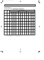
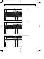
1. PERFORMANCE DATA
COOLING CAPACITY(1)
PLA-P3AA / PU(H)-P3VGAA PU(H)-P3VGAA.UK PU(H)-P3VGAA1.UK
PU(H)-P3YGAA.UK PU(H)-P3YGAA1.UK
Indoor
Indoor
intake air intake air
D.B. (:) W.B. (:)
20
16
20
18
20
20
22
16
22
18
22
20
24
24
24
26
26
26
28
28
28
30
30
30
32
32
32
34
34
34
NOTE:
16
18
20
16
18
20
16
18
20
16
18
20
16
18
20
16
18
20
20
CA
7,722
8,268
8,892
7,722
8,268
8,892
SHC
4,942
4,299
3,557
5,560
4,961
4,268
7,722
8,268
8,892
7,722
8,268
8,892
7,722
8,268
8,892
7,722
8,268
8,892
7,722
8,268
8,892
7,722
8,268
8,892
6,178
5,622
4,980
6,795
6,284
5,691
7,413
6,945
6,402
7,722
7,607
7,114
7,722
8,268
7,825
7,722
8,268
8,536
CA: Capacity (W)
P.C.: Power consumption (kW)
SHF
0.64
0.52
0.40
0.72
0.60
0.48
0.80
0.68
0.56
0.88
0.76
0.64
0.96
0.84
0.72
1.00
0.92
0.80
1.00
1.00
0.88
1.00
1.00
0.96
P.C.
2.75
2.80
2.89
2.75
2.80
2.89
2.75
2.80
2.89
2.75
2.80
2.89
2.75
2.80
2.89
2.75
2.80
2.89
2.75
2.80
2.89
2.75
2.80
2.89
Outdoor intake air D.B. (:)
25
CA
SHC
SHF
P.C.
7,488 4,792 0.64
2.91
8,034 4,178 0.52
2.96
8,697 3,479 0.40
3.03
7,488 5,391 0.72
2.91
8,034 4,820 0.60
2.96
8,697 4,175 0.48
3.03
7,488 5,990 0.80
2.91
8,034 5,463 0.68
2.96
8,697 4,870 0.56
3.03
7,488 6,589 0.88
2.91
8,034 6,106 0.76
2.96
8,697 5,566 0.64
3.03
7,488 7,188 0.96
2.91
8,034 6,749 0.84
2.96
8,697 6,262 0.72
3.03
7,488 7,488 1.00
2.91
8,034 7,391 0.92
2.96
8,697 6,958 0.80
3.03
7,488 7,488 1.00
2.91
8,034 8,034 1.00
2.96
8,697 7,653 0.88
3.03
7,488 7,488 1.00
2.91
8,034 8,034 1.00
2.96
8,697 8,349 0.96
3.03
SHC: Sensible heat capacity (W)
SHF: Sensible heat factor
9
(240V)
30
CA
7,254
7,761
8,463
7,254
7,761
8,463
SHC
4,643
4,036
3,385
5,223
4,657
4,062
7,254
7,761
8,463
7,254
7,761
8,463
7,254
7,761
8,463
7,254
7,761
8,463
7,254
7,761
8,463
7,254
7,761
8,463
5,803
5,277
4,739
6,384
5,898
5,416
6,964
6,519
6,093
7,254
7,140
6,770
7,254
7,761
7,447
7,254
7,761
8,124
SHF
0.64
0.52
0.40
0.72
0.60
0.48
0.80
0.68
0.56
0.88
0.76
0.64
0.96
0.84
0.72
1.00
0.92
0.80
1.00
1.00
0.88
1.00
1.00
0.96
P.C.
3.08
3.16
3.23
3.08
3.16
3.23
3.08
3.16
3.23
3.08
3.16
3.23
3.08
3.16
3.23
3.08
3.16
3.23
3.08
3.16
3.23
3.08
3.16
3.23
OC287-1.qxp
03.3.19 10:46 AM
Page 10
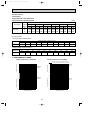
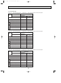
COOLING CAPACITY (2)
PLA-P3AA / PU(H)-P3VGAA PU(H)-P3VGAA.UK PU(H)-P3VGAA1.UK
PU(H)-P3YGAA.UK PU(H)-P3YGAA1.UK
Indoor
Indoor
intake air intake air
D.B. (:) W.B. (:)
20
16
20
18
20
20
22
16
22
18
22
20
24
24
24
26
26
26
28
28
28
30
30
30
32
32
32
34
34
34
NOTE:
16
18
20
16
18
20
16
18
20
16
18
20
16
18
20
16
18
20
35
CA
6,942
7,488
8,112
6,942
7,488
8,112
SHC
4,443
3,894
3,245
4,998
4,493
3,894
6,942
7,488
8,112
6,942
7,488
8,112
6,942
7,488
8,112
6,942
7,488
8,112
6,942
7,488
8,112
6,942
7,488
8,112
5,554
5,092
4,543
6,109
5,691
5,192
6,664
6,290
5,841
6,942
6,889
6,490
6,942
7,488
7,139
6,942
7,488
7,788
CA: Capacity (W)
P.C.: Power consumption (kW)
SHF
0.64
0.52
0.40
0.72
0.60
0.48
0.80
0.68
0.56
0.88
0.76
0.64
0.96
0.84
0.72
1.00
0.92
0.80
1.00
1.00
0.88
1.00
1.00
0.96
P.C.
3.30
3.39
3.47
3.30
3.39
3.47
3.30
3.39
3.47
3.30
3.39
3.47
3.30
3.39
3.47
3.30
3.39
3.47
3.30
3.39
3.47
3.30
3.39
3.47
Outdoor intake air D.B. (:)
40
CA
SHC
SHF
P.C.
6,630 4,243 0.64
3.54
7,254 3,772 0.52
3.65
7,800 3,120 0.40
3.72
6,630 4,774 0.72
3.54
7,254 4,352 0.60
3.65
7,800 3,744 0.48
3.72
6,630 5,304 0.80
3.54
7,254 4,933 0.68
3.65
7,800 4,368 0.56
3.72
6,630 5,834 0.88
3.54
7,254 5,513 0.76
3.65
7,800 4,992 0.64
3.72
6,630 6,365 0.96
3.54
7,254 6,093 0.84
3.65
7,800 5,616 0.72
3.72
6,630 6,630 1.00
3.54
7,254 6,674 0.92
3.65
7,800 6,240 0.80
3.72
6,630 6,630 1.00
3.54
7,254 7,254 1.00
3.65
7,800 6,864 0.88
3.72
6,630 6,630 1.00
3.54
7,254 7,254 1.00
3.65
7,800 7,488 0.96
3.72
SHC: Sensible heat capacity (W)
SHF: Sensible heat factor
10
(240V)
45
CA
6,318
6,786
7,332
6,318
6,786
7,332
SHC
4,044
3,529
2,933
4,549
4,072
3,519
6,318
6,786
7,332
6,318
6,786
7,332
6,318
6,786
7,332
6,318
6,786
7,332
6,318
6,786
7,332
6,318
6,786
7,332
5,054
4,614
4,106
5,560
5,157
4,692
6,065
5,700
5,279
6,318
6,243
5,866
6,318
6,786
6,452
6,318
6,786
7,039
SHF
0.64
0.52
0.40
0.72
0.60
0.48
0.80
0.68
0.56
0.88
0.76
0.64
0.96
0.84
0.72
1.00
0.92
0.80
1.00
1.00
0.88
1.00
1.00
0.96
P.C.
3.84
3.92
3.99
3.84
3.92
3.99
3.84
3.92
3.99
3.84
3.92
3.99
3.84
3.92
3.99
3.84
3.92
3.99
3.84
3.92
3.99
3.84
3.92
3.99
03.3.19 10:46 AM
Page 11
HEATING CAPACITY
PUH-P3VGAA
PUH-P3VGAA.UK PUH-P3VGAA1.UK
PUH-P3YGAA.UK PUH-P3YGAA1.UK
Indoor
intake air
-10
DB (:) CA
P.C.
15
5,906 2.07
20
5,673 2.24
25
5,487 2.38
Service Ref.
PLA-P3AA
NOTE:
(240V)
CA
6,417
P.C.
2.28
Outdoor intake air WB (:)
0
5
10
15
CA
P.C.
CA
P.C.
CA
P.C.
CA
P.C.
7,161 2.63 9,393 3.15 10,602 3.50 11,811 3.78
6,138
5,952
2.45
2.66
6,789
6,510
-5
2.84
3.08
9,068
8,556
3.40 10,230 3.78 11,393 4.06
3.61 9,858 4.04 10,974 4.36
CA : Capacity (W) P.C.: Power consumption (kW)
Correction factors
Cooling capacity correction factors
Service Ref.
PLA-P3AA
5m
10m
15m
Refrigerant piping length (one way)
20m
25m
30m
35m
40m
45m
50m
1.00
0.981
0.968
0.952
0.900
0.886
0.874
0.940
0.925
0.913
Heating capacity correction factors
Service Ref.
PLA-P3AA
5m
10m
15m
Refrigerant piping length (one way)
20m
25m
30m
35m
40m
45m
50m
1.00
0.998
0.995
0.993
0.983
0.980
0.978
0.990
0.988
0.985
2. PERFORMANCE CURVE
Cooling performance curve(50Hz)
Heating performance curve(50Hz)
Correcting the capacity line influenced by frosting
Not correcting the capactiy line influenced by frosting
1.4
CAPACITY (RATIO)
CAPACITY (RATIO)
1.4
INDOOR
W.B.(°C)
1.2
22
1.0
20
18
0.8
16
1.2
15
20
25
INDOOR
D.B.(°C)
25
20
INDOOR
D.B.(°C)
1.0
0.8
0.6
0.4
1.4
INDOOR
W.B.(°C)
TOTAL INPUT (RATIO)
22
20
18
16
1.2
TOTAL INPUT (RATIO)
OC287-1.qxp
1.0
0.8
0.6
0
10
20
30
40
15
1.0
0.8
0.6
0.4
-12 -10
0.4
-5
1.2
46
-5
0
5
10
OUTDOOR W.B.(°C)
OUTDOOR D.B.(°C)
11
15
OC287-1.qxp
03.3.19 10:46 AM
Page 12
3. ELECTRICAL DATA
3.1. Heat pump type
Indoor unit ······220V 50Hz Single phase
Service
Ref.
Outdoor unit ······220V 50Hz Single phase / 380V 50Hz 3 phase
Indoor unit
PLA-P3AA
Outdoor unit
PUH-P3VGAA
PUH-P3VGAA.UK PUH-P3YGAA.UK
PUH-P3VGAA1.UK PUH-P3YGAA1.UK
Cool
Heat
Cool
Heat
Capacity (W)
7,600
9,100
7,600
9,100
Total Input (kW) (In+Out)
3.40
3.47
3.40
3.47
Input (kW)
0.15
0.15
0.15
0.15
Current (A)
0.78
0.78
0.78
0.78
85
85
43
43
Outdoor
unit
Indoor
unit
Mode
Starting current (A)
Current (A)
(GAA)
16.37
17.43
—
—
Current (A)
(GAA(1).UK)
16.16
17.19
5.78
6.15
Indoor unit ······230V 50Hz Single phase
Service
Ref.
Outdoor unit ······230V 50Hz Single phase / 400V 50Hz 3 phase
Indoor unit
PLA-P3AA
Outdoor unit
PUH-P3VGAA
PUH-P3VGAA.UK PUH-P3YGAA.UK
PUH-P3VGAA1.UK PUH-P3YGAA1.UK
Cool
Heat
Cool
Heat
Capacity (W)
7,700
9,200
7,700
9,200
Total Input (kW) (In+Out)
3.42
3.48
3.42
3.48
Input (kW)
0.16
0.16
0.16
0.16
Current (A)
0.79
0.79
0.79
0.79
89
89
45
45
Outdoor
unit
Indoor
unit
Mode
Starting current (A)
Current (A)
(GAA)
15.66
16.67
—
—
Current (A)
(GAA(1).UK)
15.45
16.45
5.49
5.84
Indoor unit ······240V 50Hz Single phase
Service
Ref.
Outdoor unit ······240V 50Hz Single phase / 415V 50Hz 3 phase
Indoor unit
PLA-P3AA
Outdoor unit
PUH-P3VGAA
PUH-P3VGAA.UK PUH-P3YGAA.UK
PUH-P3VGAA1.UK PUH-P3YGAA1.UK
Cool
Heat
Cool
Heat
Capacity (W)
7,800
9,300
7,800
9,300
Total Input (kW) (In+Out)
3.44
3.50
3.44
3.50
Input (kW)
0.17
0.17
0.17
0.17
Current (A)
0.81
0.81
0.81
0.81
93
93
47
47
Outdoor
unit
Indoor
unit
Mode
Starting current (A)
Current (A)
(GAA)
15.01
15.98
—
—
Current (A)
(GAA(1).UK)
14.81
15.76
5.29
5.63
12
03.3.19 10:46 AM
Page 13
3.2. Cooling only type
Indoor unit ······220V 50Hz Single phase
Service
Ref.
Outdoor unit ······220V 50Hz Single phase / 380V 50Hz 3 phase
Indoor unit
PLA-P3AA
Outdoor unit
PU-P3VGAA
PU-P3VGAA.UK PU-P3YGAA.UK
PU-P3VGAA1.UK PU-P3YGAA1.UK
Cool
Cool
Capacity (W)
7,600
7,600
Total Input (kW) (In+Out)
3.40
3.40
Input (kW)
0.15
0.15
Current (A)
0.78
0.78
85
43
Outdoor
unit
Indoor
unit
Mode
Starting current (A)
Current (A)
(GAA)
16.37
—
Current (A)
(GAA(1).UK)
16.16
5.78
Indoor unit ······230V 50Hz Single phase
Service
Ref.
Outdoor unit ······230V 50Hz Single phase / 400V 50Hz 3 phase
Indoor unit
PLA-P3AA
Outdoor unit
PU-P3VGAA
PU-P3VGAA.UK PU-P3YGAA.UK
PU-P3VGAA1.UK PU-P3YGAA1.UK
Cool
Cool
Capacity (W)
7,700
7,700
Total Input (kW) (In+Out)
3.42
3.42
Input (kW)
0.16
0.16
Current (A)
0.79
0.79
89
45
Outdoor
unit
Indoor
unit
Mode
Starting current (A)
Current (A)
(GAA)
15.66
—
Current (A)
(GAA(1).UK)
15.45
5.49
Indoor unit ······240V 50Hz Single phase
Service
Ref.
Outdoor unit ······240V 50Hz Single phase / 415V 50Hz 3 phase
Indoor unit
PLA-P3AA
Outdoor unit
PU-P3VGAA
PU-P3VGAA.UK PU-P3YGAA.UK
PU-P3VGAA1.UK PU-P3YGAA1.UK
Cool
Cool
Capacity (W)
7,800
7,800
Total Input (kW) (In+Out)
3.44
3.44
Input (kW)
0.17
0.17
Current (A)
0.81
0.81
93
47
Indoor
unit
Mode
Outdoor
unit
OC287-1.qxp
Starting current (A)
Current (A)
(GAA)
15.01
—
Current (A)
(GAA(1).UK)
14.81
5.29
13
OC287-1.qxp
03.3.19 10:46 AM
Page 14
4. STANDARD OPERATION DATA
4.1. Heat pump type
Service Ref.
PLA-P3AA
Total
Mode
Cooling
Heating
Capacity
W
7,800
9,300
Input
kW
3.44
3.50
Indoor unit Service Ref.
PLA-P3AA
Electrical circuit
Phase,Hz
1,50
Volts
V
240
Amperes
A
0.81
PUH-P3VGAA
PUH-P3VGAA.UK
PUH-P3VGAA1.UK
Outdoor unit Service Ref.
Phase, Hz
PUH-P3YGAA.UK
PUH-P3YGAA1.UK
1, 50/3, 50
Volts
240/415
V
GAA
A
15.01
15.98
A
Mpa
15.76/5.63
2.38
(24.3)
0.39
(4.0)
Amperes
Discharge pressure
(kgf/F)
Suction pressure
(kgf/F)
14.81/5.29
2.30
(23.4)
0.47
(4.8)
Discharge temperature
°C
81.0
88.0
Condensing temperature
°C
44.0
45.0
Suction temperature
°C
4.8
0
Ref. pipe length
m
5
5
D.B.
°C
27
20
W.B.
°C
19
15
D.B.
°C
13.4
45.1
D.B.
°C
35
7
W.B.
°C
24
6
SHF
0.74
—
BF
0.13
—
Outdoor Indoor side
side
Refrigerant circuit
GAA(1).UK
Intake air temperature
Discharge air temperature
Intake air temperature
Mpa
The unit of pressure has been changed to Mpa based on international SI system.
f)
The conversion factor is : 1(Mpa)=10.2(kgf/f
14
03.3.19 10:46 AM
Page 15
Total
4.2 Cooling only type
Service Ref.
PLA-P3AA
Mode
Cooling
Capacity
W
7,800
Input
kW
3.44
Indoor unit Service Ref.
PLA-P3AA
Electrical circuit
Phase,Hz
1,50
Volts
V
240
Amperes
A
0.81
PU-P3VGAA
PU-P3VGAA.UK
PU-P3VGAA1.UK
Outdoor unit Service Ref.
Phase, Hz
PU-P3YGAA.UK
PU-P3YGAA1.UK
1, 50/3, 50
Volts
GAA
V
240/415
A
15.01
A
Mpa
Amperes
Discharge pressure
(kgf/F)
Suction pressure
(kgf/F)
14.81/5.29
2.30
(23.4)
0.47
(4.8)
Discharge temperature
°C
81.0
Condensing temperature
°C
44.0
Suction temperature
°C
4.8
Ref. pipe length
m
5
D.B.
°C
27
W.B.
°C
19
D.B.
°C
13.4
D.B.
°C
35
W.B.
°C
24
Refrigerant circuit
GAA(1).UK
Outdoor Indoor side
side
OC287-1.qxp
Intake air temperature
Discharge air temperature
Intake air temperature
Mpa
SHF
0.74
BF
0.13
The unit of pressure has been changed to Mpa based on international SI system.
f)
The conversion factor is : 1(Mpa)=10.2(kgf/f
5. OUTLET AIR SPEED AND COVERAGE RANGE
PLA-P3AA
Air flow
Air speed
Coverage range
m3/min.
m/sec.
m
20
4.0
5.7
w The air coverage range is the value up to the position where the air speed is 0.25m/sec.
When air is blown out horizontally from the unit at the Hi notch position.
The coverage range should be used only as a general guideline since it varies according to the size of the room and the
furniture inside the room.
15
OC287-1.qxp
03.3.19 10:46 AM
Page 16
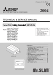
6. NOISE CRITERION CURVES
NOTCH SPL(dB)
Hi
34
Mi1
32
Mi2
30
Lo
28
PLA-P3AA
LINE
OCTAVE BAND SOUND PRESSURE LEVEL, dB re 0.002 MICRO BAR
90
80
70
NC-70
60
NC-60
50
NC-50
40
NC-40
30
NC-30
20
APPROXIMATE
THRESHOLD OF
HEARING FOR
CONTINUOUS
NOISE
NC-20
10
63
125
250
500
1000
2000
4000
8000
BAND CENTER FREQUENCIES, Hz
UNIT
Ambient temperature 27:
CEILING
Test conditions are based on JIS Z8731
1.5m
MICROPHONE
16
03.3.19 10:46 AM
6
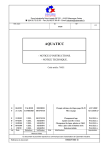
Page 17
OUTLINES AND DIMENSIONS
PLA-P3AA
Unit: mm
Ceiling hole
860 - 910
20 - 45
20 - 45
159
20 - 45
810
Suspension bolt pitch
Fresh air intake
26
159
197
20 - 45
C
89
98
192
{150
159
840
Suspension bolt M10
or W3/8
1
Feeding hole
(Drain pump)
286
374
60
860 - 910
Ceiling hole
Terminal block
840
14 - {2.8
Burring hole
Suspension bolt pitch
605
Branch duct hole
350
Drain pipe
VP-25connection
(O.D.{32)
B
190
135
Ceiling surface
30
Control wire entry
17
Power line entry
Suspension bolt lower edge
+5
0
105
50 - 70
170
140
A
2
High efficiency filter
& Fresh air intake casement (option)
17 +50
577
Air intake hole
Air intake grille
Grille
Drain hole
M
A
M
Emergency operation switch (cooling)
Emergency operation switch (heating)
Auto vane
577
Air intake hole
(WIRELESS PANEL)
411
Air outlet hole
A
950
DEFROST/STAND BY lamp
M
Receiver
77
Operation lamp
51
{175
167
155
159
130
100
90 100 100 90
Branch duct hole
(Cut out hole)
70_
OC287-1.qxp
Models
PLA-P3AA
17
M
Vane motor
411
Air outlet hole
950
1
2
Refrigerant pipe Refrigerant pipe
(9.52mm dia.)
(15.88mm dia.)
flared connection flared connection
3/8F
5/8F
77
A
B
C
241
258
80
51
Branch
duct hole
OC287-1.qxp
03.3.19 10:46 AM
7
Page 18
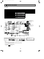
WIRING DIAGRAM
PLA-P3AA
SYMBOL
P.B
F1
ZNR
I.B
CN2L
CN32
CN41
SW1
SW2
SWE
X1
X4
FC
LED1
LED2
LED3
C
MF
SYMBOL
MV
DP
DS
H2
TB4
TB5
NAME
INDOOR POWER BOARD
FUSE(4A)
VARISTOR
INDOOR CONTROLLER BOARD
CONNECTOR(LOSSNAY)
CONNECTOR(REMOTE SWITCH)
CONNECTOR(HA TERMINAL-A)
JUMPER WIRE(MODEL SELECTION)
JUMPER WIRE(CAPACITY CODE)
SWITCH(EMERGENCY OPERATION)
RELAY(DRAIN PUMP)
RELAY(FAN MOTOR)
FAN PHASE CONTROL
POWER SUPPLY(I.B)
POWER SUPPLY(R.B)
TRANSMISSION(INDOOR-OUTDOOR)
CAPACITOR(FAN MOTOR)
FAN MOTOR
TH1
TH2
TH5
R.B
CN2
TB6
SYMBOL
W.B
RU
BZ
LED1
LED2
SW1
SW2
NAME
VANE MOTOR
DRAIN-UP MACHINE
DRAIN SENSOR
DEW PREVENTION HEATER
TERMINAL BLOCK(INDOOR/OUTDOOR CONNECTING LINE)
TERMINAL BLOCK(REMOTE
CONTROLLER TRANSMISSION LINE)
ROOM TEMP.THERMISTOR
(0:/15k",25:/5.4k" DETECT)
PIPE TEMP.THERMISTOR/LIQUID
(0:/15k",25:/5.4k" DETECT)
COND./EVA.TEMP.THERMISTOR
(0:/15k",25:/5.4k" DETECT)
REMOTE CONTROLLER BOARD
CONNECTOR(PROGRAM TIMER)
TERMINAL BLOCK(REMOTE
CONTROLLER TRANSMISSION LINE)
NAME
WIRELESS REMOTE CONTROLLER BOARD
RECEIVING UNIT
BUZZER
LED(RUN INDICATOR)
LED(HOT ADJUST)
SWITCH(HEATING ON/OFF)
SWITCH(COOLING ON/OFF)
OUTDOOR UNIT
GRILLE
MV
MV
5
MV
5
5
CN2S(WHT)
MV
5
H2
5
MF
2
1
1 2 3
DC14V
1
2
3
FAN 1 3 5
(WHT)
D.HEATER 1 3
CNC (RED)
1 2 POWER
CN2D
(WHT)
POWER
CN03
(RED)
X4
PU(H)-P3VGAA
PU(H)-P3VGAA.UK
PU(H)-P3VGAA1.UK
POWER SUPPLY
~ / N (1PHASE)
220-240V 50Hz
L
N
PE
S1
S2
S3
TB1
WHT
BRN
1 3 5
BLK
ORN
YLW
YLW
YLW
YLW
YLW
D.U.M
CNP 1 3
(BLU)
TB1
TB4
S1
S2
S3
5
BLK
WHT
YLW
ORN
BRN
DP
C
RED
ZNR
CONTROLLER BOARD OUTDOOR UNIT
CN02 (WHT)
CN01 (BLU)
1 2 3
I.B
F1
3
2
1
1 2 3 6 7 4 8 9 5 10
S1
S2
S3
P. B
POWER SUPPLY
3N~(3PHASE 4WIRES)
380-415V 50Hz
L1
L2
L3
VANE
CN6V
(WHT)
PU(H)-P3YGAA.UK
PU(H)-P3YGAA1.UK
N
PE
FC
X4
X1
X1
CN41
CN2L
W. B
BZ
CN32
1 2
1 2
LED2
LED1
SW1
SW2
CNB
REMOCON
RU
CN22
(BLU) WIRELESS
1 2 CN90
(WHT)
BLU
1 2
BLK
BLK
BLK
1 2 3
PIPE
CN29
(BLK)
BLU
D.SENSOR INTAKE LIQUID
CN21
CN31
CN20
(WHT)
(RED) (WHT)
BLK
SW1
J15
J14
J13
J12
J1 1
J24
J23
J22
J21
ON
OFF
SW2
9
LED1
BLK
SWE
LED2
BLK
LED3
R.B
DS
TH1
2
1
TH5
TH2
CN2
TB5
1 2
TB6
TRANSMISSION WIRES DC12V
SW1
MODELS
Manufacture
SW2
Service board
MODELS
Manufacture
1 2 3 4 5
PLA-P3AA
J11 J12J13J14J15
ON
OFF
Service board
1 2 3 4
PLA-P3AA
J21J22 J23 J24
NOTE:
1. Since the outdoor side electric wiring may change be sure to check the
outdoor unit electric wiring for servicing.
2. Indoor and outdoor connecting wires are made with polarities,make wiring
matching terminal numbers (S1,S2,S3).
3. Symbols used in wiring diagram above are,
/ : Terminal ,
: Connector.
18
ON
OFF
Please set the voltage using the
remote controller
.
For the setting method,please refer to
the indoor unit Installation Manual.
OC287-1.qxp
03.3.19 10:46 AM
8
Page 19
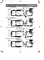
REFRIGERANT SYSTEM DIAGRAM
PLA-P3AA / PUH-P3VGAA.UK
PUH-P3YGAA.UK
Refrigerant pipe Ball valve
4-way valve
15.88mm( 5/8")
(#50)
(with heat insulator)
Strainer
Indoor unit
Thermistor
(TH1)
Thermistor
(TH5)
Unit : mm(inch)
Refrigerant flow in cooling
Refrigerant flow in heating
Flexible tube
Service
port
Muffler
Service
port
Strainer
(#50)
Flared
connection
Thermistor
(TH4)
(#50)
Strainer
Accumulator
Drier
Distributor
with
strainer
Thermistor
(TH2)
Refrigerant pipe
Stop valve
9.52mm( 3/8")
(with service port)
(with heat insulator)
PLA-P3AA / PU-P3VGAA.UK
PU-P3YGAA.UK
Thermistor
(TH1)
Flexible tube
Service
port
Strainer
(#50)
Flared
connection
(#50)
Strainer
Distributor
with
strainer
Thermistor
(TH2)
Accumulator
Drier
Refrigerant pipe
Stop valve
9.52mm( 3/8")
(with service port)
(with heat insulator)
PUH-P3VGAA1.UK
PUH-P3YGAA1.UK
Thermistor
(TH1)
Flexible tube
Service
port
Strainer
(#50)
Flared
connection
Accumulator
Thermistor
(TH2)
Refrigerant pipe
Stop valve
9.52mm( 3/8")
(with service port)
(with heat insulator)
PU-P3VGAA1.UK
PU-P3YGAA1.UK
Thermistor
(TH1)
Thermistor
(TH5)
Flexible tube
Service
port
Strainer
(#50)
Flared
connection
Distributor
with
strainer
Thermistor
(TH2)
Thermistor
(TH3)
Thermistor
(TH4)
Distributor
with
strainer
Compressor
Strainer
Strainer
(#100)
(#100)
Linear expansion valve
<4-way valve solenoid coil>
Heating ON
Cooling OFF
High pressure Outdoor unit
protect switch
Thermistor
(TH6)
Service
port
Muffler
Accumulator
Refrigerant pipe
Stop valve
9.52mm( 3/8")
(with service port)
(with heat insulator)
19
Thermistor
(TH3)
Distributor
with
strainer
Compressor
Strainer
Strainer
(#100)
(#100)
Linear expansion valve
Refrigerant flow in cooling
Refrigerant pipe Ball valve
15.88mm( 5/8")
(#50)
(with heat insulator)
Strainer
Indoor unit
Thermistor
(TH6)
Service
port
Thermistor
(TH4)
Distributor
with
strainer
PLA-P3AA / PU-P3VGAA
Strainer
Strainer
(#100)
(#100)
Linear expansion valve
Refrigerant flow in cooling
Refrigerant flow in heating
Refrigerant pipe Ball valve
4-way valve
15.88mm( 5/8")
(#50)
(with heat insulator)
Strainer
Indoor unit
Thermistor
(TH5)
Distributor
with
strainer
Compressor
High pressure Outdoor unit
protect switch
Refrigerant pipe Ball valve
15.88mm( 5/8")
(#50)
(with heat insulator)
Strainer
PLA-P3AA / PUH-P3VGAA
Thermistor
(TH3)
Refrigerant flow in cooling
Indoor unit
Thermistor
(TH5)
<4-way valve solenoid coil>
Heating ON
Cooling OFF
High pressure Outdoor unit
protect switch
Thermistor
(TH6)
High pressure Outdoor unit
protect switch
Thermistor
(TH6)
Service
port
Thermistor
(TH3)
Thermistor
(TH4)
Distributor
with
strainer
Compressor
Strainer
Strainer
(#100)
(#100)
Linear expansion valve
OC287-1.qxp
03.3.19 10:46 AM
Page 20
TROUBLESHOOTING
9
HOW TO CHECK THE PARTS
PLA-P3AA
Parts name
Check points
Room temperature
thermistor
(TH1)
Pipe temperature
thermistor
(TH2)
Condenser/Evaporator
temperature thermistor
(TH5)
Vane motor
Disconnect the connector then measure the resistance using a tester.
(Surrounding temperature 10:~30:)
Normal
Abnormal
4.3k"~9.6k"
Open or short
Measure the resistance between the terminals using a tester.
(Surrounding temperature 20:)
Fan motor
Normal
Abnormal
15k"
Open or short
Measure the resistance between the terminals using a tester.
(Surrounding temperature 20:)
Relay connector
1
(Refer to the thermistor)
Red
2 White
3 Black
1
2
3
Normal
Motor terminal
or
Relay connector
PLA-P3AA
Red-Black
87.2"
White-Black
104.1"
Abnormal
Open or short
Protector
OPEN :130:
CLOSE :80i20:
Drain pump
Measure the resistance between the terminals using a tester.
(Surrounding temperature 20:)
Red
1
Normal
Abnormal
2
290"
Open or short
Red
Drain sensor
1
2
3
Measure the resistance between the terminals using a tester.
Measure the resistance after 3 minutes have passed since the power supply was intercepted.
(Surrounding temperature 0:~60:)
Normal
Abnormal
0.6k"~6.0k"
Open or short
20
(Refer to the thermistor)
03.3.19 10:46 AM
Page 21
<Thermistor Characteristic graph>
Thermistor for
lower temperature
Room temperature thermistor(TH1)
Pipe temperature thermistor(TH2)
Condenser/evaporator temperature
thermistor(TH5)
< Thermistor for lower temperature >
50
40
Rt=15exp { 3480(
0:
10:
20:
25:
30:
40:
1
273+t
Resistance (K")
Thermistor R0=15k' ± 3%
Fixed number of B=3480k' ± 2%
1 )}
273
15k'
9.6k'
6.3k'
5.2k'
4.3k'
3.0k'
30
20
10
0
Thermistor for
drain sensor
10
-20 -10 0 10 20 30 40 50
Temperature (:)
< Thermistor for drain sensor >
9
8
Thermistor R0=6.0k' ±5%
Fixed number of B=3390k' ±2%
1
Rt= 6 exp { 3390(
273+t
0:
10:
20:
25:
30:
40:
Resistance (K")
OC287-1.qxp
1
)}
273
6.0k'
3.9k'
2.6k'
2.2k'
1.8k'
1.3k'
7
6
5
4
3
2
1
0
-20
21
0
20 40 60
Temperature (:)
80
OC287-1.qxp
10
03.3.19 10:46 AM
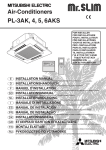
Page 22
DISASSEMBLY PROCEDURE
PLA-P3AA
Be careful on removing heavy parts.
OPERATING PROCEDURE
PHOTOS & ILLUSTRATIONS
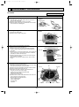
1. Removing the air intake grille
(1) Slide the knob of air intake grille toward the arrow 1 to
open the air intake grille.
(2) Remove drop prevention hook from the panel.
(3) Slide the shaft in the hinge to the direction of the arrow2
and remove the air intake grille.
Figure 1
Air intake grille
Grille
Air intake grille knob
2. Removing the fan guard
(1) Open the air intake grille.
(2) Remove the 3 screws of fan guard.
Photo 1
Screws
Fan guard
Air intake grille
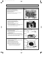
3. Removing the room temperature thermistor
(1)Remove the fan guard.(See photo 1)
(2) Remove the screw in the room temperature thermistor
holder to remove the holder and the room temperature
thermistor.
(3) Remove the 1 screw from the bell mouth, and unscrew the
other 2 screws (fix to the oval hole which has a different
diameter) to remove the bell mouth.
(4) Remove the holder claw, and remove the room temperature thermistor and holder.
(5) Disconnect the connector (red) from the indoor control
board.
Photo 2
Screws
Bell mouth
Room
temperature
thermistor
Air intake grille
4. Removing the electrical box
Photo 3
(1) Remove the fan guard.(See photo 1)
(2) Disconnect the lead wire of the vane motor from the clamp,
and disconnect the white connector (10P).
Turbo fan
(3) Remove the room temperature thermistor with the holder.
(4) Remove the bell mouth.(See photo 2)
(5) Disconnect the relay connector in the electrical box.
Red (3P) for fan motor power supply
Electrical
White (2P) for pipe temperature thermistor
box
Blue (2P) for drain pump
White (3P) for drain sensor
(6) Remove the 3 screws of the electrical box and loosen the
other 2 screws to remove the box.
<Electrical parts in the electrical box>
Power
Indoor controller board
supply
Power supply board
board
Terminal block
Capacitor
Connector
22
Nut
Capacitor
Terminal
block
Indoor controller board
Connector
OC287-1.qxp
03.3.19 10:46 AM
Page 23
OPERATING PROCEDURE
PHOTOS & ILLUSTRATIONS
5. Remove the fan motor
(1) Remove the fan guard.(See photo 1)
(2) Remove the bell mouth.(See photo 2)
(3) Remove the electrical box.(See photo 3)
(4) Remove the turbo fan nut.
(5) Pull out the turbo fan.
(6) Disconnect the connector of the fan motor lead wire.
(7) Remove the 4 nuts of the fan motor.
Photo 4
Fan motor
Nut
Nuts
6. Removing the pipe temperature thermistor
and condenser evaporator temperature thermistor
(1) Remove the fan guard.(See photo 1)
(2) Remove the bell mouth.(See photo 2)
(3) Remove the electrical box.(See photo 3)
(4) Remove the turbo fan.
(5) Remove the screw of the service panel.
(6) Remove the service panel.
(7) Remove the pipe temperature thermistor which is inserted
into the holder installed to the thin copper pipe.
(8) Disconnect the 2-pin white connector.
Photo 5
Connector
Pipe temperature thermistor
Service panel
7. Removing the panel
(1) Remove the air intake grille.(See figure 1)
Corner panel (See figure 2)
(1) Remove the corner screw.
(2) Slide the corner panel to the direction of the arrow3, and
remove the corner panel.
Panel (See photo 6)
(1) Disconnect the connector that connects with the unit.
(2) Remove the 2 screws from the panel and loosen another 2
screws, which fix to the oval holes, have different diameters.
(3) Rotate the panel a little to remove the panel.
Figure 2
Corner
Screw panel
Photo 6
Connector
Screws
Panel
Screws
8. Removing the drain pan
(1) Remove the panel. (See photo 6)
(2) Remove the drain plug (Larger one), drain the remaining
water in the drain pan.
(3) Remove the corner cover. (2 screws)
(4) Remove the bell mouth (See photo 2)
(5) Remove the electrical box. (See photo 3)
(6) Remove the lead wire holder. (1 screw)
(7) Remove the 4 screws and pull out the drain pan.
w Pull out the left and right of the pan gradually.
Be careful not to crack or damage the pan.
Panel
Corner
panel
Photo 7
Screw
Screw
Drain pan
Screw
Screw
Lead
wire
holder
23
Drain plug(Larger)
Corner cover
OC287-1.qxp
03.3.19 10:46 AM
Page 24
OPERATING PROCEDURE
PHOTOS & ILLUSTRATIONS
9. Removing the drain pump and drain sensor
(1) Remove the panel. (See photo 6)
(2) Remove the fan guard. (See photo 1)
(3) Remove the bell mouth. (See photo 2)
(4) Remove the electrical box. (See photo 3)
(5) Remove the drain pan. (See photo 7)
(6) Remove the 3 screws of the drain pump.
(7) Cut the drain hose band, pull out the drain hose from the
drain pump.
(8) Pull out the drain pump.
(9) Remove the drain sensor and the holder.
Photo 8
Drain sensor
Screw
Drain hose
Fixing band
Screw
Drain pump
10. Removing the heat exchanger
(1) Remove the panel. (See photo 6)
(2) Remove the fan guard. (See photo 1)
(3) Remove the bell mouth. (See photo 2)
(4) Remove the electrical box. (See photo 3)
(5) Remove the drain pan. (See photo 7)
(6) Remove the turbo fan. (See photo 4)
(7) Remove the 3 screws of the piping cover, and pull out
piping cover.
(8) Remove the 4 screws of the outer wall cover, and pull out
the outer wall cover.
(9) Remove the screw of the coil support.
(10) Remove the 2 screws of the coil.
(11) Pull out the heat exchanger.
Photo 9
Coil support
Coil screws
Heat exchanger
Coil
support
Coil
support
Photo 10
Screws
Outer wall cover
24
Piping cover
Screws of
piping cover
OC287-1.qxp
03.3.19 10:47 AM
11
Page 25
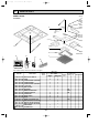
PARTS LIST
PANEL PARTS
GEAR
PLA-P3AA
13
GEAR
(VANE)
12
VANE
BUSH
2
11
10
STEPPING
MOTOR
3, 4
9
4
1
4
5
8
6
14
15
RECEIVER
7
17
18
CHECK TEST RUN
MODEL SELECT
˚C
AMPM
AMPM
CENTRALLY CONTROLLED
ON
NOT AVAILABLE
1Hr.
OFF
ON/OFF
˚C
TEMP
16
CLOCK
CHECK
˚C
STAND BY
DEFROST
ERROR CODE
TEMP.
NOT AVAILABLE
FILTER
CHECK MODE
TEST RUN
FUNCTION
ON/OFF
Part numbers that is circled is not shown in the figure.
Q'ty / set
No.
1
2
3
4
5
6
7
8
9
10
11
12
13
14
15
16
17
18
19
Parts No.
T7W E10
R01 E00
R01 E01
R01 E00
R01 E02
R01 E00
R01 E00
R01 24K
R01 E00
R01 E00
R01 E00
R01 E00
R01 E01
T7W E06
T7W E06
R01 E01
R01 E00
T7W E01
R01 E00
003
002
638
638
638
500
691
658
317
223
063
040
040
713
714
049
075
305
673
Parts Name
Specification
AIR OUTLET GRILLE
VANE
CORNER PANEL (RECEIVER)
CORNER PANEL
CORNER PANEL (MITSUBISHI)
L.L FILTER
GRILLE ASSY
RECEIVER
WIRELESS ADAPTER
STEPPING MOTOR
VANE BUSH
GEAR (VANE)
GEAR
REMOTE CONTROLLER
WIRELESS REMOTE CONTROLLER
REMOTE CONTROLLER DOOR
REMOTE CONTROLLER HOLDER
CABLE ASSY
SCREW ASSY
Remarks Wiring RecomDiagram mended
(Drawing Symbol Q'ty
No.)
WIRELESS
1
4
1
2
1
1
1
1
RU
1
W.B
4
MV
8
4
4
WIRED
1
4
3
1
1
1
4
8
4
4
1
R.B
1
1
1
1
1
25
Price
PLA -P3AA
1
Unit
Amount
OC287-1.qxp
03.3.19 10:47 AM
Page 26
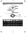
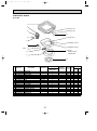
FUNCTIONAL PARTS
PLA-P3AA
RUBBER MOUNT
13
12
11
1
2
2
3
4
5
10 MOTOR CAP
SPL WASHER 6
9 CONDENSER
EVAPORATOR
TEMPERATURE
THERMISTOR
7
8 PIPE TEMPERATURE
THERMISTOR
Q'ty / set
No.
Parts No.
Parts Name
Specification
PLA-P3AA
1
2
3
4
5
6
7
8
9
10
11
12
13
R01
R01
T7W
T7W
R01
R01
T7W
R01
—
—
—
—
E10
08K
E41
E06
E32
E00
—
E06
A41
114
097
480
202
202
122
762
105
BASE
LEG
INNER COVER
LEG
TURBO FAN
SPL WASHER
HEAT EXCHANGER
PIPE TEMPERATURE THERMISTOR
CONDENSER EVAPORATOR TEMPERATURE THERMISTOR
MOTOR CAP
LEG
FAN MOTOR
D17B6P70MS
RUBBER MOUNT
1
2
1
1
1
1
1
1
1
1
1
1
4
26
Remarks
(Drawing No.)
Wiring RecomDiagram mended
Symbol Q'ty
(RG00G462G11)
(RG02G374H01)
(RG00G165G37)
(RG02G374H02)
TH2
TH5
(RG02G375H01)
MF
Price
Unit
Amount
OC287-1.qxp
03.3.19 10:47 AM
Page 27
FUNCTIONAL PARTS
PLA-P3AA
1
2
17 DRAIN PLUG
3
16 DRAIN PLUG
15
4
14 CAPACITOR
5
13 TERMINAL BLOCK
6
12 TERMINAL BLOCK
FUSE 7
11 ROOM
8
TEMPERATURE
THERMISTOR
9
10
Q'ty / set
No.
Parts No.
Parts Name
Specification
PLA-P3AA
1
2
3
4
5
6
7
8
9
10
11
12
13
14
15
16
17
R01 E02 529
R01 A41 523
T7W E05 355
R01 E00 266
R01 31K 241
R01 E00 313
T7W E00 239
T7W E27 310
—
T7W E10 675
R01 E00 202
T7W 512 716
T7W E13 716
R01 17T 255
—
R01 A48 524
R01 A41 524
DRAIN PAN
DRAIN SOCKET
DRAIN PUMP
DRAIN SENSOR
SENSOR HOLDER
POWER BOARD
FUSE
CONTROLLER BOARD
CONTROL COVER ASSY
FAN GUARD
ROOM TEMPERATURE THERMISTOR
TERMINAL BLOCK
TERMINAL BLOCK
CAPACITOR
CORNER COVER
DRAIN PLUG
DRAIN PLUG
250V / 4A
2P (1, 2)
3P (S1, S2, S3)
3.5+ 440V
27
1
1
1
1
1
1
1
1
1
1
1
1
1
1
1
1
1
Remarks
(Drawing No.)
Wiring RecomDiagram mended
Symbol Q'ty
DP
DS
P.B
F1
I.B
(RG00A239G02)
TH1
TB5
TB4
C
(RG00G623G01)
Price
Unit
Amount
OC287-1.qxp
12
03.3.19 10:47 AM
Page 28
OPTIONAL PARTS
1. TIMER
Part No.
PAC-SC32PTA (with set back function)
Model Name
Program timer
1-1. Program timer specifications
Part name
Parts No.
Exterior dimensions (inch)
Installation
Type of clock
Clock accuracy
Display-Time
-Week
-Timer setting unit
Program cycle
Timer setting unit
No. of set points
Power rating
Program timer
PAC-SC32PTA
5-4/32✕4-23/32✕23/32 (130✕120✕18mm)
Wall mount
Quartz
+
_ 50 second / month at 25:
Liquid crystal display
Liquid crystal display
Liquid crystal display
24 hours
30 minutes
48 / day
_5% (Supplied by Remote Controller)
5V DC +
1-2. Feature of program timer
(1) Daily timer function
Daily timer can be set in 30 minutes units for up to 24 hours.
Each unit can be set for unit ON, unit OFF, or setback operation.
(2) Setback operation
Set back operation is useful for reducing running costs
e.g. At a hotel with a 24-hour system
8:00~23:00 Cooling operation with set temperature at 26°C
23:00~8:00 Setback operation with 2 degrees of setback
As shown in the chart on the right, the set temperature rises 2 degrees
automatically during the setback operation. When the setback operation
ends, normal operation will begin.
(3) Weekly timer function
Daily timer function can apply to each day of the week.
28
28˚C
26˚C
8:00
Normal
operation
23:00
Setback
operation
8:00
Normal
operation
OC287-1.qxp
03.3.19 10:47 AM
Page 29
1-3. How to connect program timer
(1) Install the program timer next to the remote controller the same way as the remote controller is installed.
(2) Connect the program timer and the remote controller with a 5-wire cable as shown in the figure below
Connect to indoor unit
with 2-wire cable.
NOTE:While the program timer is connected to the remote controller, the
24hour ON/OFF timer on the remote controller will not operate.
SET
BACK
S M T W T F S
SET
FILTER
MONITOR
0
3
6
12
12
15
18
21
15
CHECK MODE
24
TEST RUN
SET/MONITOR
TODAY
WEEKLY
SETTING
SET BACK
ON
CLOCK
OFF
ON
DAILY
SETTING
SET BACK
DAILY TIMER
OFF
PROERAN TIMER
PAC-SC32PTA
4
Connect to CN1
Use 5-wire cable
Connect to CN1
1-4. Names and functions
<PAC-SC32PTA>
WEEKLY TIMER SETTING DISPLAY
CURRENT TIME DISPLAY
Used for selection of if or not the day operation pattern set by PATTERN SETTING is to
be applied in weekly day unit,
setting.
During MONITOR status,current
time is display.
During Daily timer setting, a
time desire for timer setting is
displayed.
SET BACK DISPLAY
DAILY TIMER SETTING DISPLAY
Indicates the setting set
back range.
24 hours is divided into 48 blocks and each
block express 30 minutes.
The block display consists of 3 pattern.
Set back can be done in the range of 1,2,4,6
and 8°C.
SET BACK SETTING SW
SET
SET/MONITOR DISPLAY
During SET is display, clock adjustment,
change of weekly day, daily and weekly timer
setting can be performed.
During MONITOR is display, all switches
except SET/MONITOR SW are invalidated.
This is normal status.
SET
MONITOR
SET/MONITOR
BACK
S M T W T F S
TODAY
WEEKLY
SETTING
0
3
6
12
15
12
15
18
21
24
SET BACK
ON
ON
DAILY
SETTING
Used for set back setting.
ON/SET BACK/OFF SW
SET BACK
Used to specify the time setting pattern.
CLOCK
OFF
DAILY TIMER
OFF
PROERAN TIMER
PAC-SC32PTA
WEEK DAY SETTING SW
DAILY TIMER SW
Used for week day setting.
Used for timer setting in 30 minutes unit.
MODE SELECTOR SW
CLOCK ADJUSTMENT SW
WEEKLY TIMER SW
Using this switch select “MONITOR” or “SET”
Mode.
Used for adjustment of the current time.
Used for setting timer in day of week unit.
Push
SW to advance the time. Each time the button is
pushed the time advance by 1 minute, pushing continuously
advances by 1 minute at 0.5 second interval, and when the
lower digit of minute becomes 0 indication advances in 10 minutes unit.
SW is used for reversing the time. Each time the button is
pushed the time reverses by 1 minute, pushing continuously
reverses the time by 1 minute at 0.5 second interval, and when
the lower digit of minute becomes 0 indication reverses in 10
minutes unit.
Pushing
SW moves the week day light
display in order of
S→M→T→W…
“MONITOR” :Indicates the current timer setting. All switch expect MODE
SELECTOR SW are invalidated
then.This is the normal status.
“SET”: Set to “SET” mode for clock adjustment, charge of week day, daily and
weekly timer setting.
29
enabling to set the week day.
OC287-1.qxp
03.3.19 10:47 AM
Page 30
2. Multi-Functional Casement
Part No.
PAC-SG03TM-E
Applied Service Ref.
PLA-P3AA
3. High-Efficiency Filter Element (2. Multi-Functional Casement is needed.)
Part No.
PAC-SG01KF
Applied Service Ref.
PLA-P3AA
4. Grill + Wireless Remote Controller
Part No.
PLP-6AALM
Applied Service Ref.
PLA-P3AA
5. Grill + Wired Remote Controller
Part No.
PLP-6AAM
Applied Service Ref.
PLA-P3AA
6. Remote Sensor
Part No.
PAC-SE41TS-E
Applied Service Ref.
PLA-P3AA
7. Remote Operation Adapter
Part No.
PAC-SF40RM-E
Applied Service Ref.
PLA-P3AA
8. Remote ON/OFF Adapter
Part No.
PAC-SE55RA-E
Applied Service Ref.
PLA-P3AA
9. Air Outlet Shutter Plate (20set , 2pcs/set)
Part No.
PAC-SG06SP-E
Applied Service Ref.
PLA-P3AA
30
OC287-1.qxp
03.3.19 10:47 AM
Page 31
OC287-1.qxp
03.3.19 10:47 AM
Page 32
TM
HEAD OFFICE : MITSUBISHI DENKI BLDG., 2-2-3 MARUNOUCHI CHIYODA-KU , TOKYO 100-8310 , JAPAN
cCopyright 2003 MITSUBISHI ELECTRIC ENGINEERING CO., LTD.
Distributed in Mar. 2003 No.OC287 16
Made in Japan
New publication, effective Mar. 2003
Specifications subject to change without notice