1
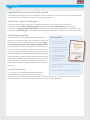
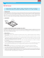
VERSION 9.2 E
ND/NU Series
Installation manual crystalline modules ND/NU Series
60 CELLS
Montageanleitung kristalline Module ND/NU-Serie
Manuel d’installation des modules cristallins Série ND/NU
Manual de instalación de los módulos cristalinos Serie ND/NU
ND-R240A2, ND-R235A2, ND-R230A2, ND-R225A2, ND-R220A2, ND-R215A2, ND-R210A2
ND-R250A5, ND-R245A5, ND-R240A5, ND-R235A5, ND-R230A5, ND-R225A5, ND-R220A5
ND-245R1J, ND-240R1J, ND-235R1J, ND-230R1J, ND-225R1J, ND-220R1J, ND-215R1J, ND-210R1J
NU-R250J5, NU-R245J5, NU-R240J5
NU-235R1H, NU-230R1H, NU-225R1H, NU-220R1H
CONTENT | INHALT | SOMMAIRE | ÍNDICE
Module registration ................................................................................................................................................................ page 4
Important safety instructions (multilingual) ....................................................................................................................... pages 8 – 14
General installation manual: ND / NU Series ..................................................................................................................... pages 15 – 18
Installation manual – photovoltaic modules: ND / NU Series (60 cells) ....................................................................................... page 19
Installation manual – electrical output and thermal characteristics .......................................................................................... page 20
Ver 9.2 E
Modulregistrierung ................................................................................................................................................................. Seite 5
Wichtige Sicherheitshinweise (mehrsprachig) ................................................................................................................... Seiten 8 – 14
Allgemeine Montageanleitung: ND / NU-Serie ................................................................................................................. Seiten 21 – 24
Montageanleitung – Photovoltaikmodule: ND / NU-Serie (60 Zellen) ......................................................................................... Seite 25
Montageanleitung – elektrische Leistung und thermische Eigenschaften ................................................................................. Seite 26
Ver 9.2 E
Enregistrement de modules ..................................................................................................................................................... page 6
Instructions importantes de securite (multilingue) ............................................................................................................. pages 8 – 14
Manuel d’installation général : série ND / NU .................................................................................................................. pages 27 – 30
Manuel d’installation – modules photovoltaïques : série ND / NU (60 cellules) .......................................................................... page 31
Manuel d’installation – caractéristiques électriques et thermiques .......................................................................................... page 32
Ver 9.2 E
Registro de los módulos ....................................................................................................................................................... página 7
Instrucciones importantes de seguridad (multilingüe) ..................................................................................................... páginas 8 – 14
Manual general de instalación: Serie ND / NU ................................................................................................................ páginas 33 – 36
Manual de instalación – Módulos fotovoltaicos: Serie ND / NU (60 células) ............................................................................ página 37
Manual de instalación – Características eléctricas y térmicas ................................................................................................ página 38
Ver 9.2 E
3
SHARP SOLAR
Congratulations on your new solar system!
You have made an excellent decision by choosing a photovoltaic system from Sharp Solar – you have chosen quality, innovation and reliability.
The solar power station from Sharp Solar is your very own state-of-the-art power source.
Sharp Solar – your trusted partner
There are many suppliers of photovoltaic systems. By deciding on Sharp Solar, you have chosen a first-class manufacturer.
tSharp Solar is one of the world’s technological leaders in solar power and has 50 years of experience in solar technology.
tSharp Solar has a complete range of solar modules for all purposes – from monocrystalline and polycrystalline to microamorphous cells.
tSharp Solar is a “Green Company” – all development, manufacturing and distribution processes comply with strict environmental standards.
Top quality guaranteed
Sharp Solar guarantees the safety, quality and value of your product over
many years – the only thing we ask you to do is to register your modules with
the serial number, so that we can send you the guarantee certificate. Regis-
Your benefits
t Claim the product and service
guarantee without difficulty
Guarantee Certifi
ter your modules quickly and easily at www.brandaddedvalue.net.
You can be proud of this certificate – and make use of extensive guarantee
services at any time. You receive proof of ownership for your photovoltaic system as soon as you have registered your modules in a quick and easy process
at www.brandaddedvalue.net. The certificate confirms that you are the owner
of your original Sharp Solar modules and also supports your guarantee claims.
Even though you will probably not need to make a claim – thanks to the high
quality of the product – the certificate is a good thing to have anyway. It is
Certificate No.:
Sample
t Receive an official guarantee
certificate with all registered
module serial numbers
t Receive confirmation that
your modules were delivered by Sharp Electronics
(Europe) GmbH
cate
Issued to:
System site:
Registered modules
:
Sharp Electronics (Europe)
GmbH grants a guarant
ee for the modules
by means of serial number
specified
s in Appendix A in accorda
terms and conditions
nce with the guarant
stipulated in the module
ee
passport. In case of
ownership of the registere
change of
d modules the registrat
ion process must be
repeated.
Hamburg,
Klaus Schäfer, Quality
Engineer Solar
Sharp Energy Solution
a division of Sharp Electronics Europe
(Europe) GmbH
Sonninstrasse 3, 20097
Hamburg, Germany
Tel: + 49 (0) 40 / 23 76
- 0 · Fax: + 49 (0) 40
/ 23 76 - 21 93
www.sharp.eu
proof that you have invested in leading technology by choosing a PV system
from Sharp.
It couldn’t be easier
t Be sure that you have an original product, as the serial
number is verified
t Proof of ownership in the event of damage or theft
You can register your unit or download registration documents here:
www.brandaddedvalue.net. We can help you at any time with any
registration questions you may have here: phone +49 (0) 1805 / 272 63 71 (14 cents/min. from German landlines, max. 42 cents/min. from
German mobile networks; cost of call from outside Germany varies on country and telephone provider).
4
PLEASE READ THIS MANUAL CAREFULLY BEFORE USING THE MODULES
IMPORTANT SAFETY INSTRUCTIONS
This manual contains important safety instructions for the PV module that must be followed during the maintenance of PV modules.
To reduce the risk of electric shock, do not perform any servicing unless you are qualified to do so.
1.
2.
3.
4.
5.
6.
7.
8.
9.
10.
11.
12.
13.
14.
The installation must be performed by a certified installer/servicer to ensure system integrity and safety.
The installation is only allowed after referring and understanding of GENERAL INSTALLATION MANUAL and INSTALLATION MANUAL – PHOTOVOLTAIC MODULES.
If you don’t have your personal copy, please contact your installer or local Sharp office listed in Sharp Solar web site : URL : http://www.sharp-world.com/solar
Do not pull the PV cables.
Do not touch any surface of module.
Do not place/drop objects onto the PV modules.
Do not disassemble or attempt to repair the PV module by yourself.
Do not drop the PV module.
Do not damage, pull, bend, or place heavy material on cables.
Upon completion of any service or repairs, ask the installer/servicer to perform routine checks to determine that the PV modules are in safe and proper operating condition.
When replacement parts are required, be sure the installer/servicer uses parts specified by the manufacturer with same characteristics as the original parts.
Unauthorized substitutions may result in fire, electric shock, or other hazard.
Consult your local building and safety department for required permits and applicable regulations.
In regions with snow, the module can sustain a snow load of up to 50 cm (when the module is mounted in the portrait orientation/short frame side facing down) or 100 cm (when the
module is mounted in the landscape orientation/long frame side facing down).
As a result of sliding snow, the mechanical load increases when the number of module rows in the matrix of a PV installation increases. When mounting the module in the portrait
orientation for more than 3 rows, the accumulated snow load may cause the lower edge of the module frame to deform. Take necessary measures (e. g. snow stopper) to avoid possible
damage.
Periodically remove any overhanging snow and/or ice from the module framework as it may cause deformation of the module frame.
CAUTION: HIGH VOLTAGE! To reduce the risk of electric shock, do not touch.
PŘED POUŽITÍM MODULŮ SI POZORNĚ PŘEČTĚTE TUTO PŘÍRUČKU
DŮLEŽITÉ BEZPEČNOSTNÍ POKYNY
V této příručce jsou uvedeny důležité bezpečnostní pokyny týkající se PV-modulu, které musíte dodržovat při jeho údržbě.
Abyste snížili nebezpečí úrazu elektrickým proudem, neprovádějte žádné servisní opravy, pokud k nim nemáte dostatečnou kvalifikaci.
1.
2.
3.
4.
5.
6.
7.
8.
9.
10.
11.
12.
13.
14.
Instalaci musí provést kvalifikovaný montér nebo servisní pracovník, který zajistí integritu a bezpečnost systému.
Před instalací je nutno přečíst si a pochopit OBECNÝ NÁVOD K INSTALACI a NÁVOD K INSTALACI FOTOVOLTAICKÉHO MODULU. Pokud nemáte svůj vlastní výtisk, obraťte
se laskavě na montéra nebo místní pobočku společnosti Sharp, která je uvedena na webové stránce Sharp Solar : URL : http://www.sharp-world.com/solar
Nevytahujte PV-kabely.
Nedotýkejte se nikde povrchu modulu.
Na PV-moduly nesmíte pokládat ani upustit žádné předměty.
Nerozebírejte a nepokoušejte se opravovat PV-modul sami.
Dávejte pozor, abyste PV-modul nepustili.
Nepoškozujte, netahejte, neohýbejte kabely, ani je nezatěžujte těžkými předměty.
Po dokončení každé údržby nebo opravy požádejte montéra nebo servisního pracovníka, aby provedl běžnou kontrolu a ujistil se, že PV-moduly jsou v bezpečném a řádném
provozním stavu.
Pokud je nutná výměna náhradních dílů, ujistěte se, že montér nebo servisní pracovník používá výhradně díly specifikované výrobcem, které mají stejné parametry jako
originální díly. Neschválené výměny mohou způsobit požár, úraz elektrickým proudem nebo jiné nebezpečí.
Pro potřebná povolení a příslušné směrnice se obraťte na místní stavební a bezpečnostní odbor.
V oblastech se sněžením modul unese sněhovou zátěž až 50 cm (je-li namontován svisle / krátká strana rámu směřuje dolů) nebo 100 cm (je-li namontován vodorovně / dlouhá
strana rámu směřuje dolů).
V důsledku klouzání sněhu se mechanická zátěž zvýší, když se zvýší počet modulových řad v matrici instalace PV. Při montáži modulu ve svislé orientaci ve více než 3 řadách
může nashromážděný sníh způsobit deformaci dolního okraje rámu modulu. V zájmu prevence škod přijměte potřebná opatření (například zábranu proti sněhu).
Pravidelně odstraňujte přečnívající sníh nebo led z rámu modulu, neboť by mohly způsobit deformaci rámu.
POZOR: VYSOKÉ NAPĚTÍ ! Nedotýkejte se, abyste snížili nebezpečí úrazu elektrickým proudem.
LÆS VENLIGST BRUGSVEJLEDNINGEN GRUNDIGT, INDEN MODULERNE BRUGES
VIGTIGE SIKKERHEDSINSTRUKTIONER
Denne manual indeholder vigtige sikkerhedsinstruktioner for PV modulet, der skal følges under vedligeholdelse af PV moduler.
For at reducere risikoen for elektrisk stød må du ikke udføre nogen form for service, medmindre du har kvalifikationerne til det.
1.
2.
3.
4.
5.
6.
7.
8.
9.
10.
11.
12.
13.
14.
Installationen skal foretages af en autoriseret elektriker for at sikre systemets integritet og sikkerhed.
Installationen er kun tilladt efter at have læst og forstået DEN GENERELLE INSTALLATIONSMANUAL og INSTALLATIONSMANUALEN – PHOTOVOLTAISK MODUL. Hvis du ikke har din
personlige kopi, bedes du kontakte din installatør eller det lokale Sharp kontor, der er oplistet på Sharp Solar hjemmesiden : URL : http://www.sharp-world.com/solar
Træk ikke PV kablerne.
Undlad at berøre modulets overflade.
Undlad at sætte/lægge genstande på PV modulerne.
Undlad at demontere eller forsøge at reparere PV modulet selv.
Undlad at tabe PV modulet.
Undlad at ødelægge, trække eller bøje kablerne eller placere tunge genstande på dem.
Efter udførelse af service eller reparation skal du bede installatøren/elektrikeren foretage rutinekontrol for at se, om PV modulerne er i sikker og korrekt funktionsbetingelse.
Når der er brug for udskiftningsdele skal du sørge for, at elektrikeren/installatøren anvender de dele, der er specificeret af producenten, med samme karakteristika som de originale dele.
Uautoriserede reservedele kan resultere i brand, elektrisk stød eller andre farer.
Konsulter den lokale bygge- og sikkerhedsafdeling for de krævede godkendelser og gældende regulativer.
I områder med sne kan modulet modstå vægten af et snelag på op til 50 cm (når modulet monteres i opretstående stilling/med den korte side af rammen nedad) eller 100 cm (når
modulet monteres liggende/med den lange af rammen nedad).
Den mekaniske belastning, der skyldes nedskridende sne, stiger, jo flere rækker af moduler den samlede PV-installation består af. Når der monteres mere end 3 rækker af moduler
i opretstående stilling, kan vægten af den ansamlede sne føre til, at den nederste kant på modulets ramme deformeres. Træf de nødvendige foranstaltninger (f. eks. snestop) for at
forebygge eventuelle skader.
Sne og/eller is, der hænger ud over modulets ramme, skal fjernes fra tid til anden, da det kan føre til deformation af modulets ramme.
FORSIGTIG: HØJSPÆNDING! Undlad berøring for at reducere risikoen for elektrisk stød.
8
ΠΑΡΑΚΑΛΟΥΜΕ ΔΙΑΒΑΣΤΕ ΠΡΟΣΕΚΤΙΚΑ ΑΥΤΟ ΤΟ ΕΓΧΕΙΡΙΔΙΟ ΠΡΟΤΟΥ ΧΡΗΣΙΜΟΠΟΙΗΣΕΤΕ ΤΙΣ ΜΟΝΑΔΕΣ
ΣΗΜΑΝΤΙΚΕΣ ΟΔΗΓΙΕΣ ΑΣΦΑΛΕΙΑΣ
Αυτό το εγχειρίδιο περιέχει σημαντικές για τη φωτοβολταϊκή μονάδα, οι οποίες πρέπει να τηρούνται κατά τη διάρκεια της συντήρησης των μονάδων.
Για να αποφευχθεί ο κίνδυνος ηλεκτροπληξίας, μην πραγματοποιήσετε κανενός είδους συντήρηση αν δεν έχετε την κατάλληλη εξειδίκευση.
1.
2.
3.
4.
5.
6.
7.
8.
9.
10.
11.
12.
13.
14.
Η εγκατάσταση θα πρέπει να πραγματοποιηθεί από πιστοποιημένο ειδικό εγκατάστασης / συντήρησης για τη διασφάλιση της ακεραιότητας και ασφάλειας του συστήματος.
Η εγκατάσταση επιτρέπεται μόνο αφού διαβάσετε και κατανοήσετε το ΓΕΝΙΚΟ ΕΓΧΕΙΡΙΔΙΟ ΕΓΚΑΤΑΣΤΑΣΗΣ και το ΕΓΧΕΙΡΙΔΙΟ ΕΓΚΑΤΑΣΤΑΣΗΣ –
ΦΩΤΟΒΟΛΤΑΪΚΗ ΜΟΝΑΔΑ. Αν δεν έχετε το προσωπικό σας αντίγραφο, παρακαλούμε επικοινωνήστε με τον τεχνίτη εγκατάσταση ή το τοπικό γραφείο
της Sharp, από τον κατάλογο που αναφέρεται στην ιστοσελίδα : Διεύθυνση URL : http://www.sharp-world.com/solar
Μην τραβάτε τα φωτοβολταϊκά καλώδια.
Μην αγγίζετε καμία επιφάνεια της μονάδας.
Μην τοποθετείτε / ρίχνετε αντικείμενα πάνω στις φωτοβολταϊκές μονάδες.
Μην αποσυναρμολογείτε τη φωτοβολταϊκή μονάδα ούτε να αποπειραθείτε να την επισκευάσετε μόνος σας.
Μην αφήσετε να σας πέσει η φωτοβολταϊκή μονάδα.
Μην προκαλείτε ζημιές στα καλώδια, ούτε να τα τραβάτε, να τα τσακίζετε ή να τοποθετείτε πάνω τους βαριά υλικά.
Κατά την ολοκλήρωση οποιωνδήποτε εργασιών συντήρησης ή επισκευών, ζητήστε από τον ειδικό εγκατάστασης / συντήρησης να πραγματοποιήσει τους συνήθεις ελέγχους
έτσι ώστε να διαπιστώσει ότι οι φωτοβολταϊκές μονάδες λειτουργούν σωστά και με ασφάλεια.
Όταν απαιτείται η αντικατάσταση εξαρτημάτων, βεβαιωθείτε ότι ο ειδικός εγκατάστασης / συντήρησης χρησιμοποιεί τα εξαρτήματα που ορίζονται από τον κατασκευαστή με
χαρακτηριστικά ίδια με τα αυθεντικά εξαρτήματα. Οι μη εξουσιοδοτημένες αντικαταστάσεις μπορούν να οδηγήσουν σε πυρκαγιά, ηλεκτροπληξία και άλλους κινδύνους.
Συμβουλευτείτε το τοπικό σας τμήμα εγκαταστάσεων και ασφάλειας για τις απαιτούμενες άδειες και τις ισχύουσες κανονισμούς.
Σε περιοχές με χιόνι, η μονάδα μπορεί να αντέξει φορτίο χιονιού έως 50cm (όταν η μονάδα είναι εγκατεστημένη σε κατακόρυφο προσανατολισμό / με τη μικρή πλευρά
στραμμένη προς τα κάτω) ή έως 100 cm (όταν η μονάδα είναι εγκατεστημένη σε οριζόντιο προσανατολισμό / με τη μεγάλη πλευρά στραμμένη προς τα κάτω).
Επειδή το χιόνι έχει την τάση να γλιστράει, το μηχανικό φορτίο αυξάνεται, όταν αυξάνεται ο αριθμός των σειρών των μονάδων σε μια φωτοβολταϊκή εγκατάσταση. Κατά την
εγκατάσταση της μονάδας σε οριζόντιο προσανατολισμό για περισσότερες από 3 σειρές, το συνολικό φορτίο χιονιού ενδέχεται να προκαλέσει παραμόρφωση στο κατώτερο
άκρο του πλαισίου της μονάδας. Λάβετε τα απαραίτητα μέτρα (π. χ. στόπερ χιονιού), για να αποτρέψετε πιθανή φθορά.
Να αφαιρείτε περιοδικά το συσσωρευμένο χιόνι ή/και τον πάγο από την επιφάνεια της μονάδας, καθώς ενδέχεται να προκληθεί παραμόρφωση στο πλαίσιο της μονάδας.
ΠΡΟΣΟΧΗ: ΥΨΗΛΗ ΤΑΣΗ! Μην αγγίζετε, κίνδυνος ηλεκτροπληξίας.
SI PREGA DI LEGGERE ATTENTAMENTE IL PRESENTE MANUALE PRIMA DI UTILIZZARE I MODULI
IMPORTANTI ISTRUZIONI DI SICUREZZA
Il presente manuale contiene importanti istruzioni di sicurezza per i moduli fotovoltaici, che devono essere seguite attentamente quando si utilizzano questi
moduli.
Al fine di ridurre il rischio di scosse elettriche, non eseguire alcuna operazione di manutenzione o riparazione, a meno che non si possiedano le competenze
necessarie.
1.
2.
3.
4.
5.
6.
7.
8.
9.
10.
11.
12.
13.
14.
L’installazione deve essere eseguita da un addetto all’installazione/manutenzione qualificato, per garantire l’integrità e la sicurezza del sistema.
È possibile eseguire l’installazione solo dopo aver letto e compreso il MANUALE GENERALE D’INSTALLAZIONE e il MANUALE D’INSTALLAZIONE – MODULO FOTOVOLTAICO.
In caso l’utente non sia in possesso di una copia dei suddetti manuali, si prega di rivolgersi al proprio addetto all’installazione o al punto vendita Sharp più vicino, indicato al sito
Internet Sharp Solar: URL : http://www.sharp-world.com/solar
Non tirare i cavi del modulo fotovoltaico.
Non toccare alcuna superficie del modulo.
Non posizionare/lasciar cadere oggetti sul modulo fotovoltaico.
Non smontare né tentare di riparare il modulo fotovoltaico senza l’assistenza di un tecnico qualificato.
Non lasciar cadere il modulo fotovoltaico.
Non danneggiare, tirare, piegare né posizionare materiali pesanti sui cavi.
Al termine delle operazioni di manutenzione o riparazione, chiedere all’addetto all’installazione/manutenzione di eseguire i controlli di routine per stabilire che i moduli fotovoltaici siano
in perfette condizioni di funzionamento.
In caso di necessità di pezzi di ricambio, assicurarsi che l’addetto all’installazione/manutenzione utilizzi i pezzi di ricambio indicati dal fabbricante, con le stesse caratteristiche dei pezzi
originali. Sostituzioni non autorizzate potrebbero provocare incendi, scosse elettriche o altre situazioni pericolose.
Rivolgersi all’ufficio locale responsabile per la sicurezza e l’edilizia per quanto riguarda i permessi necessari e le relative disposizioni.
Nelle zone soggette a innevamento, il modulo è in grado di sostenere un carico di neve fino a 50 cm (quando il modulo è installato con orientamento verticale/con il lato corto del telaio
rivolto verso il basso) o 100 cm (quando il modulo è installato con orientamento orizzontale/con il lato lungo del telaio rivolto verso il basso).
Come conseguenza dello scivolamento della neve, il carico meccanico aumenta all’aumentare del numero di righe di moduli nella matrice di un impianto fotovoltaico. Installando
il modulo con orientamento verticale per più di 3 righe, il carico della neve accumulata può causare una deformazione del bordo inferiore del telaio del modulo. Adottare le misure
necessarie (ad es. fermaneve) per evitare possibili danni.
Rimuovere periodicamente la neve e/o il ghiaccio sporgenti dal telaio dei moduli perché possono causare deformazioni al modulo stesso.
ATTENZIONE: ALTA TENSIONE! Al fine di ridurre il rischio di scosse elettriche, non toccare.
11
GENERAL INSTALLATION MANUAL
ND / NU Series
PLEASE READ THIS MANUAL CAREFULLY BEFORE INSTALLING OR USING THE MODULES.
PLEASE PASS ALONG THE ATTACHED USER MANUAL (PAGE 8 – 14) TO YOUR CUSTOMER.
1. INTRODUCTION
This Installation Manual contains essential information for the electrical and mechanical installation that you must know before installing Sharp PV modules. This
also contains safety information you need to be familiar with. All the information described in this manual are the intellectual property of Sharp and based on the
technologies and experiences that have been acquired and accumulated in the long history of Sharp. This document does not constitute a guaranty, expressed or
implied. Sharp does not assume responsibility and expressly disclaims liability for loss, damage, or expense arising out of or in any way connected with installation,
operation, use or maintenance of the PV modules. No responsibility is assumed by Sharp for any infringement of patents or other rights of third parties that may
result from use of PV module. Sharp reserves the right to make changes to the product, specifications or installation manual without prior notice.
2. COMPONENTS
Junction box
Connector
Electrical cable
Glass
Frame
Cell
3. GENERAL INFORMATION (INCLUDING WARNING AND SAFETY)
The installation of PV modules requires a great degree of skill and should only be performed by a qualified licensed professional, including licensed contractors and
licensed electricians. Please be aware that there is a serious risk of various types of injury occurring during the installation including the risk of electric shock. All
Sharp PV modules are equipped with a permanently attached junction box that will accept variety of wiring applications or with a special cable assembly for ease of
installation, and they do not require special assembly.
< GENERAL WARNING >
1. PV modules are heavy. Handle with care.
2. Before you attempt to install, wire, operate and maintain the PV module, please make sure that you completely understand the information described in this
installation manual.
3. Contact with electrically active parts of a PV module such as terminals can result in burns, sparks and lethal shock whether the PV modules is connected or
not.
4. PV modules produce electricity when the sufficient sunlight or other sources illuminate the module surface. When the modules are connected in series, voltage is
cumulative. When the modules are connected in parallel, current is cumulative. As a result, a large-scale PV system can produce high voltage and current which
could present an increased hazard and may cause serious injury or death.
5. Do not connect the PV modules directly to the loads such as motor since the variation of the output power depending on the solar irradiation causes damage for
the connected motor.
1: In the case of a brushless motor, the lock function becomes active and the hall IC is most likely to be damaged.
2: In the case of a brush type motor, the coil is most likely to be damaged.
6. In case of snow build-up, snow would slide easier on the smooth surface of the module than other parts of the roof. Snow may suddenly slide, fall off the roof
and hit nearby objects/areas. Take preventive measures (e. g. snow stopper) when there is possible risk such case would cause an injury or a damage.
< GENERAL SAFETY >
1. Consult local codes and other applicable laws concerning required permits on regulations concerning installation and inspection requirements.
2. Before installing a PV module, contact appropriate authorities to determine permit, installation and inspection requirements that should be followed.
3. Install PV modules and ground frames in accordance with applicable rules and regulations.
4. PV modules should be installed and maintained by qualified personnel. Only installer/servicer personnel should have access to the PV module installation site.
5. No matter where the PV modules are installed, either roof mounted construction or any other type of structures above the ground, appropriate safety practices
should be followed and required safety equipment should be used in order to avoid possible safety hazards. Note that the installation of some PV modules on
roofs may require the addition of fireproofing, depending on local building/fire codes.
Ver 9.2 E
15
GENERAL INSTALLATION MANUAL
6.
7.
8.
9.
10.
11.
12.
13.
14.
15.
16.
17.
18.
19.
20.
In the case that the PV modules are non-integral type, the module is to be mounted over a fire resistant roof.
Please use PV modules with same cell size within series.
Follow all safety precautions of other components used in the system.
In order to avoid a risk of injury or electrical shock, do not allow anyone to approach the PV module if the person has little knowledge on PV module or on the
measures that should be taken when PV modules are damaged.
Do not shade portions of the PV module surface from the sunlight for a long time. The shaded cell may become hot (hot spot phenomenon) which results in
solder joints peeling off. Shading causes drop in generated power and/or operation failure of the PV modules.
Do not clean the glass surface with chemicals. Do not let water stay on the glass surface of PV modules for a long time. This creates a risk of white efflorescence
(glass disease) which may result in the deterioration of energy generation.
Do not install the PV module horizontally. It may cause dirt or white efflorescence (glass disease) due to water.
Do not cover the water drain gap of the frame. There is a risk of frost damage when the frame is filled with water cumulation.
When sliding snow load has to be considered, an appropriate measure has to be taken so that PV module frames on lower edge of PV modules will not be
damaged.
Do not expose PV module to sunlight concentrated with mirrors, lenses or similar means.
Turn off inverters and circuit breakers immediately, should a problem occur.
In case the glass surface of a PV module is broken, wear goggles and tape the glass to keep the broken pieces in place.
A defective PV module may generate power even if it is removed from the system. It may be dangerous to handle the PV module while exposed to sunlight. Place
a defective PV module in a carton so PV cells are completely shaded.
In case of series connection, the maximum open circuit voltage must not be greater than the specified maximum system voltage. The voltage is proportional
to the number of series. In case of parallel connection, please be sure to take proper measure (e. g. fuse for protection of module and cable from over current,
and/or blocking diode for prevention of unbalanced strings voltage) to block the reverse current flow. The current may easily flow in a reverse direction.
Keep modules away from children.
< HANDLING SAFETY >
1. Do not cause an excessive load on the surface of PV module or twist the frame. The glass surface can easily break.
2. Do not stand or step on the PV module. The surface glass of PV module is slippery.
3. Do not hit or put excessive load on the glass or back sheet. The PV cell is very thin and can be easily broken.
4. Do not scratch or hit at the back sheet. The back sheet is vulnerable.
5. Do not hit on the terminal box or do not pull the cables. The terminal box can crack and break.
6. Never touch terminal box or the end of output cables with bare hands when the PV module is irradiated. Cover the surface of PV module with cloth or other
suitable sufficiently opaque material to isolate the PV module from incident light and handle the wires with rubber-gloved hands to avoid electric shock.
7. Do not scratch the output cable or bend it with force. The insulation of output cable can break and may result in electricity leakage or shock.
8. Do not pull the output cable excessively. The output cable may unplug and cause electricity leakage or shock.
9. Do not drill holes in the frame. It may compromise the frame strength and cause corrosion of the frame.
10. Do not scratch the insulation coating of the frame (except for grounding connection). It may cause corrosion of the frame or compromise the framework
strength.
11. Do not loosen or remove the screws of the PV module. It may compromise the joint strength of PV module and cause corrosion.
12. Do not touch the PV module with bare hands. The frame of PV module has sharp edges and may cause injury.
13. Do not drop PV module or allow objects to fall down on the PV module.
14. Do not try artificially to concentrate sunlight on the PV module.
15. Do not grab the PV module at only one side. The frame may bend. Grab the PV module at two sides facing each other.
< INSTALLATION SAFETY >
1. Always wear protective head gear, insulating gloves and safety shoes (with rubber soles).
2. Keep the PV module packed in the carton until installation.
3. Do not touch the PV module unnecessarily during installation. The glass surface and the frames get hot. There is a risk of burn, or you may collapse because of
electric shock.
4. Do not work under rain, snow or windy conditions.
5. Use insulated tools.
6. Do not use wet tools.
7. Do not drop tools or hard objects on PV modules
8. When installing PV modules far above ground, do not drop any object (e. g., PV module or tools).
9. Make sure flammable gases are not generated near the installation site.
10. Completely cover the PV module surface with an opaque material during PV module installation and wiring.
11. Plug in the connector tight and ensure the wiring work.
16
Ver 9.2 E
GENERAL INSTALLATION MANUAL
12. Due to the risk of electrical shock, do not perform any work if the terminals of PV module are wet.
13. Do not touch the terminal box and the end of output cables, the cable ends (connectors), with bare hands during installation or under sunlight, regardless of
whether the PV module is connected to or disconnected from the system.
14. Do not unplug the connector if the system circuit is connected to a load.
15. Do not stomp on the glass at work. There is a risk of injury or electric shock if glass is broken.
16. Do not work alone (always work as a team of 2 or more people).
17. Wear a safety belt if working far above the ground.
18. Do not wear metallic jewelry which can cause electric shock during installation.
19. Do not damage the back sheet of PV modules when fastening the PV modules to a support by bolts.
20. Do not damage the surrounding PV modules or mounting structure when replacing a PV module.
21. Bind cables by the insulation locks. Drooping down of cables from the terminal box could possibly cause various problems such as animal biting, electricity leakage in puddle.
22. Take proper measures for preventing the laminate (consisted of resin, cells, glass, back sheet, etc.) from dropping out of the frame in case the glass is broken.
23. Cables shall be located so that they will not be exposed to direct sunlight after installation to prevent degradation of cables.
24. If batteries are used with modules, follow safety precautions of the battery manufacturer.
25. In case of extreme snow build-up, the weight of the snow may cause the module’s frame to deform. Take appropriate preventive measures to minimize any possible resulting damage.
4. SITE SELECTION
In most applications, the PV modules should be installed in a location where there is no shading throughout the year. In the Northern Hemisphere, the PV modules
should typically face south, and in the Southern Hemisphere, the PV modules should typically face north.
Please make sure that there are no obstructions in the surroundings of the site of installation. Take proper steps in order to maintain reliability and safety, in case
the PV modules are used in areas such as: Heavy snow areas/Extremely cold areas/Strong wind areas/Installations over, or near, water/Areas where installations are
prone to salt water damage(*)/Small islands or desert areas.
(*) If you are planning to use the PV modules where the salt water damage may be possible, please consult with Sharp local agent first to determine an appropriate installation method, or to
determine whether the installation is possible.
5. TILT ANGLE
The tilt angle of the PV module is the measured between the PV module and a horizontal ground surface. The PV module generates the maximum output power
when it faces the sun directly.
5 degrees or more is recommended for the tilt angle of the PV module for the maintenance (See 11. Maintenance).
For the standalone systems with a battery where the PV modules are attached to a permanent structure, the tilt angle of the PV modules should be determined to
optimize the performance when the sunlight is the scarcest. In general, if the electric power generation is adequate when the sunlight is the scarcest, then the angle
chosen should be adequate during the rest of the year. For grid-connected installations where the PV modules are attached to a permanent structure, it is recommended to tilt the PV module at the angle equal to the latitude of the installation site so that the power generation from the PV module will be optimum throughout
the year.
6. WIRING
To ensure proper system operation and to maintain your guaranty, observe the correct cable connection polarity (Figures 1 & 2) when connecting the modules to a
battery or to other modules. If not connected correctly, the bypass diode could be destroyed.
PV modules can be wired in series to increase voltage. Connect wires from the positive terminal of one module to the negative terminal of the next module. Figure 1
shows modules connected in series.
Connect PV modules in parallel to increase current. Connect wires from the positive terminal of one module to the positive terminal on the next module. Figure 2
shows modules connected in parallel.
FIGURE 1: SERIES FOR MORE VOLTAGE
FIGURE 2: PARALLEL FOR MORE CURRENT
Ver 9.2 E
17
GENERAL INSTALLATION MANUAL
7. INSTALLATION
Refer to installation manual of PV module.
8. ELECTRICAL RATINGS
Refer to installation manual of PV module.
9. GROUNDING
The frame grounding must consider the local requirement and regulation at the site of installation. When grounding is required, please refer to below example connection (Figure 3). Please be careful in arranging the system ground so that the removal of one module from the circuit will not interrupt the grounding of any other
modules.
The modules should be grounded to the same electrical point as described below. Each PV module has a hole on the side frame for either a bolt, nut and washer
grounding the module to the frame, a ground lug fastened by bolt or screw, or appropriate screw (hardware not provided). Near the hole for ground, either
“ ” or “G“ is indicated as ground symbol. An example of acceptable ground connection using a bolt, nut and washer retaining a ground lug is shown in figure 3.
In a connection of this type, the hardware (such as a toothed locked washer/star washer) must score the frame surface to make positive electrical contact with the
frame. The ground wire must be considered within the local requirement of local and regulation at the site of installation.
FIGURE 3: EXAMPLE OF ACCEPTABLE GROUND CONNECTION
Hexagon nut
Toothed lock washer
Side frame
Wire binding lug
Wire
Wire insert
Hexagon Head bolt
Screw terminal
10. MOUNTING
Please make sure that all the information described in the installation manual is still valid and proper for your installation. The mounting method has been verified by
Sharp and NOT CERTIFIED by a third party organization.
The approved way to mount Sharp PV modules to a support structure is using the bolt holes provided as described in the Specifications. Although Sharp does not
specify or warrant frame clips or clamps, using frame clips (not provided) or clamps (not provided) is also possible when they are designed for PV modules and with
minimum dimensions on the sides of the module in accordance with the instructions and drawings provided. If using frame clips or clamps, the modules should
be fixed rigidly and there shall be no damage to the modules by deforming mounting structure against design load. The Sharp module guaranty may be void if
customer-selected frame clips which are improper or inadequate with respect to the module properties (including strength or material) or installation. Note that if
metal clips are used, there must be a path to ground from the clips, (for instance, using star washers in the clip hardware set).
Please review the descriptions and drawings carefully; not mounting the modules according to one of these methods may void your guaranty. These mounting
methods are designed to allow module loading of 2,400 Pa. Support structures that PV modules are mounted on should be rigid. Sharp PV modules are designed to
secure their electric performance under the condition that they are mounted on rigid support structures. Deformation of support structure may damage PV module
with its electric performance. When mounting the module on structure, ensure that no corner has a displacement of more than 2 mm per every 1,000 mm of the
diagonal.
11. MAINTENANCE
The modules are designed for long life and require very little maintenance. If the angle of the PV module is 5 degrees or more, normal rainfall is sufficient to keep
the module glass surface clean under most weather conditions. If dirt build-up becomes excessive, clean the glass surface only with a soft cloth using water. If cleaning the back of the module is required, take utmost care not to damage the back side materials. In order to ensure the operation of the system, please check the
connection of wiring and the state of the jacket of wires every now and then. For PV modules with anti-reflective coating glass (ND-R250A5 to ND-R220A5 and
NU-R250J5 to NU-R240J5), do not touch the glass since finger prints or stains will easily mark the glass. If dirt build-up becomes excessive, clean the glass surface
with water only.
18
Ver 9.2 E
INSTALLATION MANUAL – PHOTOVOLTAIC MODULES
ND / NU Series (60 cells)
ND-R240A2, ND-R235A2, ND-R230A2, ND-R225A2, ND-R220A2, ND-R215A2, ND-R210A2, ND-R250A5, ND-R245A5,
ND-R240A5, ND-R235A5, ND-R230A5, ND-R225A5, ND-R220A5, ND-245R1J, ND-240R1J, ND-235R1J, ND-230R1J, ND-225R1J,
ND-220R1J, ND-215R1J, ND-210R1J, NU-R250J5, NU-R245J5, NU-R240J5, NU-235R1H, NU-230R1H, NU-225R1H, NU-220R1H
1. INSTALLATION
The mounting method has been verified by Sharp and NOT CERTIFIED by a third party organization. Please review the descriptions and drawings carefully; not
mounting the modules according to one of these methods may void your guaranty. These mounting methods are designed to allow module loading of 2,400 Pa.
Mounting Using Frame Bolt Holes (Figures 1 & 2)
The modules may be fastened to a support using the bolt holes in the bottom of the frame at location “C”, as shown in Figure 1 (back view of the module) and
Figure 2 (mounting detail). The module should be fastened with four (4) M8 bolts. Recommended torque 12.5 Nm.
Mounting Using Clips on Long Edge of Module: Long Edge Parallel to Array Rails (Figure 4)
The modules may be mounted using clips (clamps) designed for solar modules as shown in Figures 3 and 4. Note that the clip positions are important – the clip
centerlines must be between 150 mm and 410 mm from the end of the module. The module must be supported along the length of the long edge, and should
overlap the array rail by at least 10 mm. Note that the mounting clips should meet the minimum dimensions (catch width of 5 mm and length of 38 mm) as shown in
Figure 3. The array rails must support the bottom of the frames and must be continuous pieces (no breaks in the rail).
Mounting Using Clips on Long Edge of Module: Long Edge Perpendicular to Array Rails (Figure 5)
The modules may also be mounted using clips on the long sides of the module when the array rails are perpendicular to the long sides, as shown in Figure 5. The clip
centerlines must be between 150 mm and 410 mm from the ends of the module. Note that the mounting clips should meet the minimum dimensions (catch width of
5 mm and length of 38 mm) shown in Figure 3. The array rails must support the bottom of the modules and must be continuous pieces (no breaks in the rail).
2. ELECTRICAL INSTALLATION INSTRUCTION
Cable characteristics
Conductor size: 4.0 mm2, Cable type: XLPE cable (CE cable), Maximum DC voltage: 1.8 kV, Ambient temperature: –40 °C to +90 °C, Maximum conductor temperature: 120 °C
Module configuration (Recommend)
# Maximum series configuration: please refer to Table 1 (This value is calculated under the condition of Voc at –40 °C.)
# Maximum parallel configuration: (Parallel connection of each string shall be conducted with following two options. Any other parallel connections are prohibited.)
a) Case of using the diodes; 1 diode per maximum 2 parallel strings (Connect a diode or more in series for every string or every 2 parallel strings for protection of
module from reverse current over load.)
b) Case of using the fuses; 1 fuse per every string (Connect a fuse for every single string for protection of module from reverse current over load.)
Connection cables requirement
The module is fitted with SMK Corporation connectors (CCT9901-2451F/CCT9901-2361F) which are mechanically and electrically compatible with Multi-Contact AG
(PV-KST4/PV-KBT4) as of 7th April 2011. To extend the module connecting leads, only use Multi-Contact AG (PV-KST4/PV-KBT4), or SMK Corporation connectors
under the same series.
3. WARNING
Do not stand or step on the PV module (Glass, Frame, Film and Terminal box). For PV modules with anti-reflective coating glass (ND-R250A5 to ND-R220A5,
NU-R250J5 to NU-R240J5), do not touch the glass since finger prints or stains will easily mark the glass. If dirt build-up becomes excessive, clean the glass surface
with water only.
FIGURE 1
FIGURE 2
FIGURE 3
For your reference, please use the washer
specified as below for the minimum requirement:
1) Spring washer
Material stainless steel
Diameter M8 8.2 / 15.4 mm
Thickness 2 mm (reference value)
Solar module
Washer
C
C
C
Bolt M8 X 20 mm
Washer
Spring Washer
Nut
C
FIGURE 4
2) Washer
Material stainless steel
Diameter M8 8.5 / 15.5 mm
Thickness 1.6 mm (reference value)
FIGURE 5
Frame
Clip
Rail
10 mm Min.
Support width
FIGURE 6
e
e
s
s
e
e
s
s
150 mm < e < 410 mm
38 mm Min.
Catch length
5 mm Min.
Catch length
High ( 100 kg)
Middle ( 50 kg)
Low
150 mm < s < 410 mm
Withstand load capability
Ver 9.2 E
19
INSTALLATION MANUAL – PHOTOVOLTAIC MODULES
Electrical output and thermal characteristics
Rated electrical characteristics of Isc, Voc, are within ±10 percent of the indicated values and +5 /–0 % of Pmax (power measurement tolerance: ± 3 %), under
STC (standard test conditions) (irradiance of 1,000 W/m2, AM 1.5 spectrum, and a cell temperature of 25 °C (77 °F)). The guaranty conditions are specified elsewhere
in this manual.
Table 1. Electrical characteristics (at STC)
Model name
Maximum
power
(Pmax)
Tolerance
Opencircuit
voltage (Voc)
ND-R240A2
240 W
+5 % / –0 %
37.2 V
8.52 A
30.4 V
Voltage at
Short-circuit point of max.
current (Isc) power (Vmpp)
Current at
point of max.
power (Impp)
Maximum
system
voltage
Overcurrent
protection
Application
class
Maximum series
configuration(*)
7.90 A
1,000 V
15 A
A
21
ND-R235A2
235 W
+5 % / –0 %
37.1 V
8.38 A
30.4 V
7.74 A
1,000 V
15 A
A
21
ND-R230A2
230 W
+5 % / –0 %
37.0 V
8.24 A
30.3 V
7.60 A
1,000 V
15 A
A
21
ND-R225A2
225 W
+5 % / –0 %
36.9 V
8.10 A
30.3 V
7.43 A
1,000 V
15 A
A
21
ND-R220A2
220 W
+5 % / –0 %
36.8 V
7.96 A
30.2 V
7.29 A
1,000 V
15 A
A
21
ND-R215A2
215 W
+5 % / –0 %
36.7 V
7.82 A
30.2 V
7.13 A
1,000 V
15 A
A
21
ND-R210A2
210 W
+5 % / –0 %
36.6 V
7.68 A
30.1 V
6.98 A
1,000 V
15 A
A
22
ND-R250A5
250 W
+5 % / –0 %
37.6 V
8.68 A
30.9 V
8.10 A
1,000 V
15 A
A
21
ND-R245A5
245 W
+5 % / –0 %
37.3 V
8.62 A
30.7 V
7.99 A
1,000 V
15 A
A
21
ND-R240A5
240 W
+5 % / –0 %
37.2 V
8.57 A
30.4 V
7.90 A
1,000 V
15 A
A
21
ND-R235A5
235 W
+5 % / –0 %
36.8 V
8.49 A
30.3 V
7.76 A
1,000 V
15 A
A
21
ND-R230A5
230 W
+5 % / –0 %
36.4 V
8.41 A
30.3 V
7.61 A
1,000 V
15 A
A
22
ND-R225A5
225 W
+5 % / –0 %
36.0 V
8.33 A
30.2 V
7.46 A
1,000 V
15 A
A
22
ND-R220A5
220 W
+5 % / –0 %
35.6 V
8.25 A
30.0 V
7.35 A
1,000 V
15 A
A
22
ND-245R1J
245 W
+5 % / –0 %
37.1 V
8.60 A
30.4 V
8.06 A
1,000 V
15 A
A
21
ND-240R1J
240 W
+5 % / –0 %
36.9 V
8.52 A
30.0 V
8.00 A
1,000 V
15 A
A
21
ND-235R1J
235 W
+5 % / –0 %
36.7 V
8.44 A
29.8 V
7.89 A
1,000 V
15 A
A
21
ND-230R1J
230 W
+5 % / –0 %
36.6 V
8.36 A
29.5 V
7.80 A
1,000 V
15 A
A
22
ND-225R1J
225 W
+5 % / –0 %
36.6 V
8.28 A
29.3 V
7.68 A
1,000 V
15 A
A
22
ND-220R1J
220 W
+5 % / –0 %
36.5 V
8.20 A
29.2 V
7.54 A
1,000 V
15 A
A
22
ND-215R1J
215 W
+5 % / –0 %
36.5 V
8.12 A
29.0 V
7.42 A
1,000 V
15 A
A
22
ND-210R1J
210 W
+5 % / –0 %
36.4 V
8.03 A
28.8 V
7.30 A
1,000 V
15 A
A
22
NU-R250J5
250 W
+5 % / –0 %
37.9 V
8.76 A
31.0 V
8.07 A
1,000 V
15 A
A
21
NU-R245J5
245 W
+5 % / –0 %
37.5 V
8.73 A
30.5 V
8.04 A
1,000 V
15 A
A
21
NU-R240J5
240 W
+5 % / –0 %
37.3 V
8.63 A
30.2 V
7.95 A
1,000 V
15 A
A
21
NU-235R1H
235 W
+5 % / –0 %
37.9 V
8.49 A
30.3 V
7.76 A
1,000 V
15 A
A
21
NU-230R1H
230 W
+5 % / –0 %
37.7 V
8.43 A
30.0 V
7.67 A
1,000 V
15 A
A
21
NU-225R1H
225 W
+5 % / –0 %
37.5 V
8.37 A
29.7 V
7.58 A
1,000 V
15 A
A
21
NU-220R1H
220 W
+5 % / –0 %
37.3 V
8.31 A
29.4 V
7.49 A
1,000 V
15 A
A
21
(*) The maximum series number of modules depends on the local conditions. These values are calculated under the condition of Voc at –40 °C.
Under normal conditions, a photovoltaic module is likely to experience conditions that produce more current and /or voltage than reported at Standard Test Conditions. Accordingly, the values of Isc and Voc marked on this module should be multiplied by a factor of 1.25 when determining component voltage ratings, conductor
capacities, fuse sizes and size of controls connected to the module output.
Application Class
This module is rated as “Application class A” according to IEC61730.
“Application class A” means:
General access, hazardous voltage, hazardous power applications
Modules rated for use in this application class may be used in systems operating at greater than 50 V DC or 240 W, where general contact access is anticipated.
Modules qualified as application class A in IEC 61730 are considered to meet the requirements for safety class II.
Fire Rating
This module is rated as “Fire safety class C” according to IEC61730.
20
Ver 9.2 E
This is Why
SHARP ENERGY SOLUTION EUROPE
A DIVISION OF SHARP ELECTRONICS (EUROPE) GMBH
SONNINSTRASSE 3,
20097 HAMBURG,
GERMANY,
TEL: + 49 (0) 40 / 23 76 - 0,
FAX: + 49 (0) 40 / 23 76 - 21 93
Ver 9.2 E
www.sharp.eu/solar