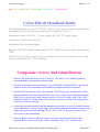
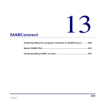
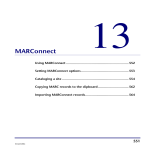
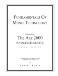
1
Comet's homepage
Sida 1 av 15
Comet's Radio Page!!!!
New
Oppskrift på beam ant for 27 Mhz
Scanner og frekvenser for Norge
Modification for Alan 78 plus
Radio Modifications
Modifications For: President Lincoln
Modifications for Presiden George:
How to change to the international configuration 240 ch, 15 W AM/FM, 21 W SSB.
Programming:
a)Turn your set on by pushing POWER.
b)Turn your set off by pushing POWER.
c)Depress POWER and keep pressed down.Your set goes on and then goes off.
d)Keep POWER depressed and press PA and DIMMER simultaneously.
e)Release POWER while keeping PA and DIMMER pressed down:"codE" flashes in the display for
5 seconds.
f)"codE" disappears and the display remains lit up.
g)Release PA and DIMMER.
h)Press M1, the display goes out.
i)Enter Your access code, then press POWER. Your set is now the international configuration.
Available functions in the international configuration:
DIMMER
In the international configuration only, the DIMMER key allows change band, thereby giving you
the use of 240 channels.
A short depression allows you to advance by one band at a time - A B C D E F A... (6 bands, 40
channels)
A longer depression allows you to do the same thing in reverse - F E D C B A F ...
SELECT:
This key allows you to go up or down by 5 KHz at a time around the reference channel. It it used in
conjunction whit the "CH(up) " y "CH (down)" keys.
How to return to the French norm 40 channels,4 W peak AM/FM/SSB
a)Turn your set on by pushing POWER.
b)Turn your set off by pushing POWER.
http://www.geocities.com/SunsetStrip/Studio/7160/radio.htm
2004-04-07
Comet's homepage
Sida 2 av 15
c)Depress POWER and keep pressed down.Your set goes on and then goes off.
d)Keep POWER depressed and press PA and DIMMER simultaneously.
e)Release POWER while keeping PA and DIMMER pressed down:"codE" flashes in the display for
5 seconds.
f)"codE" disappears and the display remains lit up.
g)Release PA and DIMMER.
h)Press PROGRAM: the sidplay goes off.
i)Enter your access code, then press POWER. Your set is now in the French configuration.
How to return to 40 channels, 4W FM
a)Turn your set on by pushing POWER.
b)Turn your set off by pushing POWER.
c)Depress POWER and keep pressed down.Your set goes on and then goes off.
d)Keep POWER depressed and press PA and DIMMER simultaneously.
e)Release POWER while keeping PA and DIMMER pressed down:"codE" flashes in the display for
5 seconds.
f)"codE" disappears and the display remains lit up.
g)Release PA and DIMMER.
h)Press M3:the sidplay goes off.
i)Enter your access code, then press POWER. Your set is now in 40 channels 4W FM configuration.
More modification to George
When executing the sequence for International mode, instead of pressing M1 press the mode button
to get UK 40 channel 4w FM.
Disply Test For President George:
a)Turn your set on by pushing POWER.
b)Turn your set off by pushing POWER.
c)Depress POWER and keep pressed down.Your set goes on and then goes off.
d)Keep POWER depressed and press M1 and CH19 simultaneously.
e)Release POWER while keeping PA and DIMMER pressed down:"codE" flashes in the display for
5 seconds.
f)"codE" disappears and the display remains lit up.
g)Then press POWER. All functions come's up in the display.Press M1 to international
configuration.
If anyone can supply me with more code's for George, please mail me!
If anyone requires Modifications for Cb-Radio Mail Me!
I have Modifications for Most Radios, But I Haven't the Time To Write them all in This Page..
President's Homepage
http://www.geocities.com/SunsetStrip/Studio/7160/radio.htm
2004-04-07
Comet's homepage
Sida 3 av 15
Cte International's Hompage
Homer's mods
More modifications
My Rig:
Tx/Rx: President George 240 ch, 30 W AM/FM, 40 W SSB
Tx/Rx: Alan 78 +u ,400 ch , 4w Fm
Antenna: Cbs 18 (1/2 wave ant. 9.9 db gain)
Mic: Sadelta Echo Master Pluss Classic
Other Modifciations
l
l
l
l
l
l
l
l
l
l
Cobra 148GTL-DX (Late) / Superstar 360 Fm
Galaxy 99
Mc 145 106 Pll
Ranger RCI 1295 (old/new)
AH-100 Cherokee
Emperor 5010
MB8719 Pll
Pll 02A
Uniden HR2510
Midland 79-290
Expanding the MB8719
Models include:- Uniden Grant/Madison, Cobra 148/2000 GTL etc.
Note: Some newer Uniden's now have RCI 18719 "clone" PLL. You will have to replace the
PLL with the old MB 8719 BEFORE attempting these mods.
To get coverage from 27.455 - 28.045, find the MB 8719 PLL, then locate pins 10, 11 and 12.Cut the
http://www.geocities.com/SunsetStrip/Studio/7160/radio.htm
2004-04-07
Comet's homepage
Sida 4 av 15
track going to these pins. Locate a ground (chassis or track). Using a DPDT Center off switch,
Connect the switch to pin 10,11,12 (IC side of the cut) on the MB 8719 PLL. This mod will give you
the normal "FCC" channels in the center position. In the down position 27.605 - 28.045, In the up
position 27.455 - 27.605 ( on channels 2 - 14 ).
Expanding the Cobra 148GTL-DX/Superstar 360 Fm (PB010)
Clip off the YELLOW, WHITE, & PINK wires from the channel 9 panel switch. Reconnect
WHITE & PINK together for normal LED channel display. Cut off the GRAY wire from the
HI/LO TONE panel switch. Remove the grounding jumper at pin 9 of the MC 145 106 PLL chop.
Connect a small bare wire between the center terminals of the now free poles of the CHANNEL 9 &
TONE switches. Add the tow 7N914 diodes and additional wiring as shown below.
The extra frequencies will now appear in the Ch. Position of the CHANNEL SELECTOR with the
BAND selector in the HIGH position.(The first 11 channels are repeats of existing channels) The "ch
9" position activates the expansion. In the LO TONE position you will get 28.195 Mhz (ch 12) to
28.495 ( ch 40). If you pull IC7 pins 4 & 2 HIGH at the same times you will get up to 28.705 Mhz.
This would need a three position switch.
Emperor 5010
1. Remove the four screws holding the bottom cover in place.
2. Lift the bottom cover enough to clear the case and slide it to the side while being careful not to
detach the speakers wires.
3. You should now see the PLL/CPU board at the front of the radio.
4. With the front of the radio facing you, locate R539 and R540 at the lower rigth corner of the
large chip (HD6140810), R539/R540 are side by side and very small.
5. Remove R539 and R540. You now will get 26.500 Mhz to 27.999 Mhz plus "FCC" band in
nine bands.
Galaxy 99
1. Remove the case and find the small circuit board (E0T004410Z) connected to the left side of
the radio as viewed from the component side of the main chassis.
2. Find the wire that is connected to this circuit board (in step1) Remove wire.
3. Remove small screw that holds the small board on to the chassis.
4. Under the board you will find a 7 pin plug that not connected to anything. Insert this plug into
http://www.geocities.com/SunsetStrip/Studio/7160/radio.htm
2004-04-07
Comet's homepage
Sida 5 av 15
the empty socket on the small circuit board.
5. Replace screws back into the small board and close case.
MC145106 PLL
This Pll includes the follow models…Browning Mark 4A, Dak Mark V, Robyn 440, Dak Mark IX,
Lake 600, Palomar SSB500 (late), Regency CB501, CBE 54CB, Keycomm 1000
For Export Models eg. Cobra 148 GTL-DX see here
Also these UNIDEN "clones" use this chip…Connex 3300, Excalibur base, Excalibur
samurai,Galaxy 2100,Galaxy II, Galaxy Pluto, Galaxy Saturn, President Franklin, Superstar 3600,
Superstar 3900, Super Galaxy, Texas Star.
This PLL is getting used in a lot of newer radio's. It often has a pair of MC4008 binary adders to
extend the amount of channels available.The PLL used 9 bit binary programming with internal
pulldown resistors.
Modifications are possible by chanhing the programming of pin 17 (P0) to pin 9 (P8) or changing the
mixing crystal.
PLL02A
The PLL02A is the worlds most popular chip used in all the Cybernet chassis. It is simple to modify
by changing the binary programming or changing the loop mixing crystal. The US versions use 10
Mhz crystal, Export use 10 or 20 Mhz crystals depending on the model.
The formula for working out the new crystal is :-New Xtal = Current 10 Mhz Xtal ± (N*0.1125) or
New Xtal=Current 20 Mhz Xtal + or -(N*0.225),where N is the number of 40 channel segments
above or below the `legal` 40 channels.
So a crystal of (10.0525 Mhz + 0.1125 Mhz) or 10.165 Mhz would give you 40 channels starting at
27.415 Mhz etc.
http://www.geocities.com/SunsetStrip/Studio/7160/radio.htm
2004-04-07
Comet's homepage
Sida 6 av 15
Ranger RCI 2950
The only difference between the old and new versions of the RC12950 is the new CUP
board.They require slightly different modifications.
OLD VERSION
The old version of the radio can be expanded from 26Mhz to 32Mhz. Although the use of
the 30-32 Mhz range may need realignment
First find the PC board whit the jumpers on ( behind the front panel). Then find `J2`,there
is a jumper on pins P3 and P4. If this is jumper is removed you will be from 26 Mhz to
32 Mhz( re tuning may be needed to operate in 30-32Mhz range).
The CUP now needs to be reset by pressing the button located below `J2`
NEW VERSION
As the CUP board has changed the modification is different. On the CUP board there is
only one jumper whit two positions avilable. In one position it covers 28 Mhz to 30
Mhz,in the other it covers 26Mhz to 30 Mhz. But if you jump all three pins together
you`ll get 26 Mhz to 30 Mhz.(If this is incorrect PLEASE tell me)
Uniden HR2510
This radio can be expanded to cover 26-30 Mhz without the need to realign!
Find IC3 15 (UC1201A,UC1170,UC1250a etc) on the sythesizer board PB121BB.Then
locate pins 34 and 35 on the chip, these pins are grounded on the HR2510. But on the
European models like the President Lincon they are tied high(+5 Vdc).
Therefor to get the extended coverage needed these pins should be tied high. This can be
done in the following way.
On the solder side of the synth board pins 34 & 35 are grouended by the same trace. With
a razor blade cut this ground trace.
Now find resistor pack RR301. The left pin of this pack is unused and goes to a solder
http://www.geocities.com/SunsetStrip/Studio/7160/radio.htm
2004-04-07
Comet's homepage
Sida 7 av 15
pad. Now connect a Small jumper wire between this solder pad and pins 34 & 35 on IC3
15.
Now you should get coverage from 26.000 Mhz to 29.990 Mhz in the following banks.
Band A: 28.000 to 28.490 Mhz
Band B: 28.500 to 28.900 Mhz
Band C: 29.000 to 29.490 Mhz
Band D: 29.500 to 29.900 Mhz
Band E: 26.000 to 26.490 Mhz
Band F: 26.500 to 26.490 Mhz
Band G: 26.965 to 27.405 Mhz
Band H: 27.000 to 27.490 Mhz
Band I: 27.500 to 27.990 Mhz
Cherokee AH-100
To expand this radio to 400 channels, do the following.
1. Remove the back cover.
2. Find the small circuit board that has the PTT and UP/DOWN switches.
3. On the reverse side of this PCB look for 3 solder islands that end on the outside edge
of the board.
4. Solder a bridge across all three islands.
5. Re-assemble radio.
6. Then do the following...
If the radio has been used before you will need to remowe the battery and the power
switch ON short out the supply terminals for about a day. This will cause the processor to
clear it`t self.
http://www.geocities.com/SunsetStrip/Studio/7160/radio.htm
2004-04-07
Comet's homepage
Sida 8 av 15
Make sure the power switch is on hold the receiver but no display, release the CH9
button and the display should reappear.
Now using the CH9 button you should be able to select 10 bands of 40 channels (A thru
J ). Now whenever you power up the radio with the CH9 button held down you`ll get 400
channels.. If you do not hold the CH9 button down you will get the standard 40 channels.
Midland 79-290
To set radio foe 240 channel mode press and hold "DW" and "9" then turn radio on..
Select bands by using the "19" button.
To ste radio for 28Mhz to 29.7 Mhz press and hold "LCR" and "eMIC"e then turn radio on. To
switch back to 40 channel mode repeat process.
Power Tweaks
0 MB8719 PLL
0 Cobra 148GTL-DX(late)/Superstar 360FM
0 Cobra HH-40
0 PLL 02A
0 Ranger RC12950
0 Variable Power for cobra 25/29 LTD
http://www.geocities.com/SunsetStrip/Studio/7160/radio.htm
2004-04-07
Comet's homepage
Sida 9 av 15
MB8719 Power
Cobra 148/2000GTL
President(Uniden) `Grant`/`Madison` (new)
L38, TR24-AM, VR11-SSB, VR12-AM PWR
Cobra 140/142GTL
Courier Galaxy
Midland 79-900
President `Washington`/`McKinley`(new)
Realistic TRC450/490
Robyn SB505D(new version)
SBE LCMS-8, LCBS-8
Superstar 360
Teaberry Stalker IX, XV, XX
Tram D80, D300
L36, TR32-AMC, VR7-SSB PWR, VR6-AM PWR
Cobra 46/47XLR, 50/55XLR
Midland 63-445
L112, L109, VR105
Cobra 148 GTL-DX/Superstar 360FM Power
This is for the cobra 148 GTL-DX late model only (PB010AB)
http://www.geocities.com/SunsetStrip/Studio/7160/radio.htm
2004-04-07
Comet's homepage
Sida 10 av 15
L44, VR-13-AM PWR, TR32-AMC, VR12-ALC, VR5-FM DEV
Cobra HH-40 Handheld Radio
This handheld radio uses the LC7230 PLL, But as it is all surface mount components this
mod should only be tackled by persons who feel confident to do so :)..
Summery of mods :- RV-201 - `S` meter adjust, RV-301-`TX` meter adjust..
Am power :-L304,L305,L306,L307
Modulation (This is the hard part)..
Remove R243 (2K2 surface mount, marked `222`, black in color, just above the marking
`R243`
Remove C225 (0. 22uF surface mount, no number, tan in color, just below C226, which,
in turn is just belowe the `C226` marking.
Component Access And Identification
1. Remove the front and rear covers (4 screws). The frint cover (with the speaker)
stays attached by the speaker and mic leads.
2. On the back by the rear circuit board, you will find RV201 and RV301, and all the
inductor coils, all are identified with numbers printed on the circuit board.
3. On the front circuit board (the side with the LCD facing you), desolder the 4 pads
that ground the front circuit board to the case. Two of these have tangs that must be
bent poen to release the board. Remove the two screws on either side of the LCD
(friction fit only). Fold the front circuit board over and out of the way exposing the
front face of the rear board.
4. Orient the unit horizontally with the antenna jack facing to your left and the bottom
of the transformer visable on the right. The printed component numbers should read
right -side-up.Locate the markings `R243` and `C226` in the area near the lower left corner of the transformer.
5. Remove R243, which is black in color, vertically orientated, just above the
marking`R243` and to left of the `Q205` marking. It has `222` marked on it.
http://www.geocities.com/SunsetStrip/Studio/7160/radio.htm
2004-04-07
Comet's homepage
Sida 11 av 15
6. C225 is not marked. Start by finding C226, which is a horizontally orientated, tan
component located just below the `C226` marking. DO NOT DISTURB C226.
PLL02A Power
AM only using L7, L11, L12, RV2-AMC
Bowman CB910, 920, 930, CBH990
Colt 290, 390, 800, SX33
Delco(GM) 1987 series
Gemtronics GT44, GT55, GTX66
GE 3-5804D, 5811B, 5812A, 5813B, 5814B, 5819A
Ham Int`l 8040 W/T
HyGain 2702, 2703
Jc Penny 981-6204, 6218
Kraco KCB4010, 4020, 4030, 4045, 5001
Lafayette HB640, HB740, HB940
Telsat 1140, LM100, LM300
Comstst 525
Midland 76-858, 76-863, 77-830, 77-838, 77-849, 77-857. 77-888, 77-889, 77-899, 77955, 77-963
Medallion 63-030
Mopar 4094176, 4094177, 4094178
Morse/Electrophonics 3005
Palomar 4100
Pearce-Simpson Lion 40, tiger 40
Ray Jefferson CB845
http://www.geocities.com/SunsetStrip/Studio/7160/radio.htm
2004-04-07
Comet's homepage
Sida 12 av 15
RCA 14T260, 270, 275, 303, 304, 305
Truetone CYJ4832A-87, 4834A-87, 4862A-87
AM only using L106, L109, L110, RV102-AMC
23 Channel :
Delco (GM) 1977 series, CBD-10
GE 3-5810B
HyGain 2680, 2681, 2683, 2679
Krayco KCB2320B, 2330B
Lafayette HB650, HB750, HB950, Telsat 1050, COm-Phone 23A, Micro 223A
Midland 13-830, 13-857B, 13-882C, 13-888B, 13-955
Pearce-Simpson Tiger Mark 2
RCA 14T300, 14T301
Truetone MCC4434B-67, CYJ4732A-77
40 channel:
HyGain 2679A, 2682, 2701, 2710X
Pearce-Simpson tiger 40A
SSB w/PTBM048A0X main bd.
L7, L11, L13, RV12-AMC, RV2-ALC, RV11-SSb MIC GAIN, VR4-AM PWR
Bowman CB950
http://www.geocities.com/SunsetStrip/Studio/7160/radio.htm
2004-04-07
Comet's homepage
Sida 13 av 15
Colt 480, 485, 1000, 1200, 485DX
Gemtronics GTX77
GE 3-5825A
HyGain 2705(V), VIII(3108), 2785
Jc Penny 981-6247
JIL SSB-M6, MPL-5
LAFAYETTE tELSAT SSB-140, 1200FM
Major 360
Midland 78-976, 79-892
Palomar 2900
RCA 14T302
Truetone CYJ4837A-87
RC12950 Power
VR14-AMC
L34, L13, L14, L16-AM Power
VR13-AM High power
VR15-AM Low power
VR12-SSB high power ALC
VR16-SSB low power ALC
http://www.geocities.com/SunsetStrip/Studio/7160/radio.htm
2004-04-07
Comet's homepage
Sida 14 av 15
Variable power for cobra 25 & 29LTD
Cobra 25 LTD
Find and remove C70 & JP6(near Final).
Disconnect ORANGE and BROWN wires from the RF Gain Control, then connect these
wires together.
Install Q1 (see diagram) where JP6 was. The right leg(emitter) of Q1 in the hole near the
final. The Centre leg(collector) in the other hole.
Solder a wire from the left leg(base) of Q1 to the center tag of the RF Gain Control.
Remowe VR5(near transformer)
Connect the last tag of the RF Gain Control to a 100ohm resistor and solder to L6 pot.
Solder a wire from the upper tag of the RF Gain Control to the top connection of VR5
(already removed)
Cut D9 out fo the circuit (this is the clipping Diode)
Put plenty of heat sink compound into the tab of Q1, then using the proper mounting
hardware mount to heat sink ( make sure that the tab of Q1 is insulated from the heat
sink)
Follow instructions for cobra 25LTD, except remove C73 &JP36 instead of C70&JP6,
remove VR4 instead of VR5, Also cut D11 insead of D9.
Q1=TIP120(Radio Shack), capacitor = 22 uF 25 V
Back
Last updated Aug 2001 by Inge Hagen
http://www.geocities.com/SunsetStrip/Studio/7160/radio.htm
2004-04-07
Comet's homepage
http://www.geocities.com/SunsetStrip/Studio/7160/radio.htm
Sida 15 av 15
2004-04-07